STEAM PUMP.
Reading edition
An Independent Steam Pump is virtually an engine with two cylinders, one for the steam piston, the other for the water piston or plunger, and is used in connection with a steam boiler for supplying it with water. The discharge pipe of a pump is generally connected with a feed water heater of some sort, which heats the water to a high temperature before entering the boiler, though there is a late pattern of steam pump which delivers the feed water to the boiler at about the same temperature as the injector. The cylinder of steam pump should always be well oiled before starting in the morning and stopping at night. The stuffing boxes on piston and valve rod should in all cases be kept well filled with soft and moist packing. If the packing is allowed to become dry and hard, it will cut the rod, inducing leakage and necessitating repairs. When a steam pump is not in use in cold weather all the drain, drip and pet cocks should be left open, to allow the water to run out. While most farm engines are furnished with an independent steam pump, some are equipped with what is called a cross-head pump.
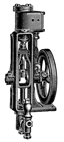
J. I. Case Steam Pump.
A Cross-Head Pump is operated by a plunger attached to the cross-head of engine and has two valves, a supply and a discharge valve, also is supplied with an air chamber. This style of pump is available only when engine is running. Engines with a cross-head pump should always be supplied with an injector to be used in case of failure of pump to work and while engine is shut down. The cross-head pump is connected to the heater in the same manner as an independent pump.
Q. How high will the steam pump lift water?
A. A steam pump will lift or draw water about 33 feet, as with one inch area, 33 feet of water will weigh 14.7 lbs., but the pump must be in very good order to lift 20 feet and all pipes must be absolutely air tight. A pump will give better satisfaction lifting from 10 to 15 feet. No pump however good will lift hot water, for the reason that as soon as air is expelled from the barrel of the pump the vapor occupies the space, thereby destroys the vacuum and interferes with the supply of water. When necessary to pump hot water, place the pump below the supply, so that the water will flow into the valve chamber. Always have a strainer at lower end of suction or supply pipe. A pump should be set up so that it is accessible for inspection, cleaning and repairs, and so that the shortest and straightest suction and delivery pipes can be used.
MARSH STEAM PUMP.
The Marsh Steam Pump is so constructed that the exhaust steam may be turned into the suction, thereby condensing its exhaust steam and returning it with its heat to the boiler, thus heating the feed water to a high degree.
The pump is automatically regulated and can never run too fast to take suction, or should the water supply give out when the throttle valve is wide open no injury can occur to the moving parts.
The steam valve, though nicely fitted, moves freely in the central bore of the steam chest, and has no mechanical connection with other moving parts of the pump, but is actuated to admit, cut off and release the steam by live steam currents which alternate with the reciprocation of the piston.
Each end of the valve is made to fit the enlarged bore of the steam chest, and it is due to these large valve heads, which present differential areas to the action of steam and the perfect freedom of the valve to move without hindrance from other mechanical arrangements or parts, that the flow of steam into the pump is automatically regulated.
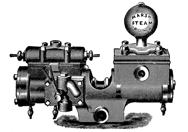
MARSH PUMP. Capacity 10 to 35 Horse-Power.
The steam valve does not require setting, as it has no dead center and will always start when steam is admitted.
The steam piston is double and each head is provided with a metal packing ring. The piston rod is made of Tobin bronze, the stuffing boxes and water piston are made of brass, and the water cylinder is brass lined. The water valves may be removed for inspection by simply taking off the air chamber.
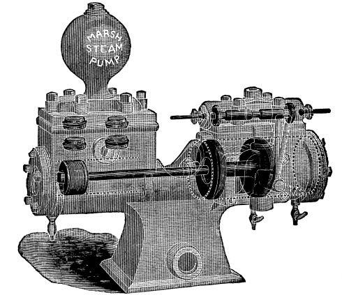
View of Marsh Steam Pump, Showing Water Valves, Steam Valves, Suction Chamber and Piston.
DIRECTIONS FOR SETTING UP AND RUNNING.
Before connecting the steam pipes, blow out with steam pressure the chips and dirt in the steam pipes. Always use the union furnished with the pump. It has a gauze gasket in it to catch the dirt that may get into the valve. Before starting pump, open air cock in delivery pipe and turn exhaust lever back, away from the air chamber. Then open throttle valve wide and allow pump to exhaust into the air until it takes suction, when deflecting lever may be thrown forward toward air chamber and cold water in the pump will condense the exhaust and return it to the boiler.
If pump refuses to work, the difficulty is to be looked for in the valve chest. Do not take off the chest. The valve may be taken out and cleaned but never filed. The valve must be returned through same end as taken from. Before closing, be sure that the head is screwed tight on the valve, using the socket wrench furnished.
When the pump is stopped, pull the exhaust lever back, so the condensed steam from leak of throttle valve will not go into the pump. It is safer also in cold weather to take off head of water end. Slight but constant lubrication adds much to the regular working of the pump. Be sure there are no leaks in the suction pipe, and when water is raised more than 10 feet, a foot valve should be put in. Compress the packings on piston rod as little as possible and yet prevent the escape of steam. Before leaving the pump in cold weather, break the suction and allow it to run empty for a minute with all the cocks open, then be sure the throttle valve is closed tight. When necessary, pack the joints under the steam chest, side plate and air chamber with manilla paper or thin rubber.
HEATER.
The Heater is used on an engine in connection with a boiler for heating the feed water before it enters the boiler under steam pressure. It is usually constructed of a shell of cast or boiler iron into which live or exhaust steam is admitted. This shell usually contains a series of pipes or a coil of pipe, through which the feed water is forced by the pump, the water thereby being heated to a high temperature before entering the boiler.
EJECTOR.
An Ejector is a machine for lifting water from various depths and forcing it to various heights with steam pressure, as follows:
With 20 pounds steam pressure an ejector will lift water to a level from 16 or 17 feet below and force it to a height of 15 or 16 feet.
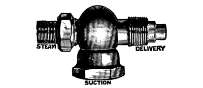
American Ejector.
With 60 pounds steam pressure will lift 20 feet and force to a height of 60 feet.
With 100 pounds steam pressure will lift 23 feet and force to a height of 107 feet.
An ejector may be placed in any position to suit the convenience in piping; they require but three connections, steam, suction and delivery.
JET PUMP.
A Jet Pump is a machine used for drawing water and discharging it above the surface level. It will draw water to a level from 10 or 15 feet below and discharge it at a height of about one foot to every pound steam pressure applied.
A jet pump has three connections, steam, suction and delivery, and may be placed in any position to suit convenience in piping.
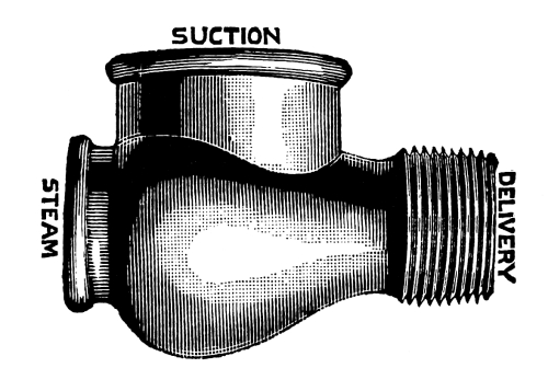
American Jet Pump.
STEAM GAUGE.
A Steam Gauge is an instrument used for indicating in pounds the amount of steam pressure upon each square inch of surface of the boiler. It is very delicately constructed, and should not be tampered with after once being set to indicate correctly. If a steam gauge is found not to indicate the exact pressure in the boiler it should be sent to the factory for repairs. Never attempt to repair it unless all the appliances for so doing are at hand.
A steam gauge should always be placed on a boiler with a syphon, or by tying a knot in the pipe between it and the boiler, so that the steam may condense, thereby allowing the water to operate it. If steam is allowed to enter, the heat would tend to expand the tube in the gauge and it would indicate more than the real pressure.
A steam gauge is usually constructed with a hollow, flat tube, called the Bourdon spring. This tube is bent in a simple curve and fastened at one end, the other end is free and by a simple clock work actuates the pointer which indicates upon the dial the steam pressure per square inch upon the boiler.
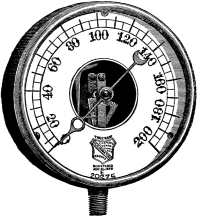
Ashcroft Steam Gauge.
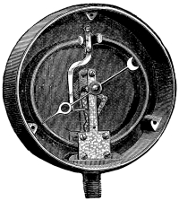
Interior Ashcroft Steam Gauge.
Q. What should be done in case the steam gauge becomes defective?
A. When the steam gauge has become broken by freezing or otherwise, and there is none on hand, the engineer may run by setting the safety valve so that it will blow off within from ten to fifteen pounds less than it is ordinarily set at, and then by careful firing, run until a new gauge can be procured, which should be done without delay.
Some engineers have been known to make a practice of running without a steam gauge.
Q. Would you recommend this method?
A. No, it must be resorted to only in case of a sudden accident and where shutting down would cause great loss. Every engineer should have an extra steam gauge on hand, to be used in case of accident to the one in use.
SAFETY VALVE.
Safety Valves, or pop valves, as they are sometimes termed, are made in many different kinds and styles, but the one most commonly used on a farm engine is constructed with a coil spring, which is adjustable, to allow the valve to pop off at a certain pressure. When the pressure exceeds this amount, it raises the valve from its seat and allows the surplus steam to escape. It should be set with the steam gauge, to allow a little margin of steam pressure over that which is necessary to drive the load, and should be compared with the steam gauge frequently to see that it works accurately. It is furnished with a lever for raising the valve, which should be raised occasionally to see that it operates freely.
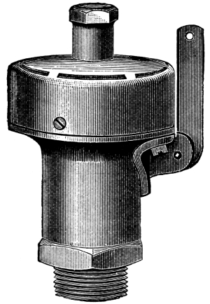
Kunkle Safety Valve.
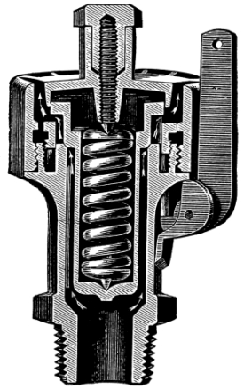
Kunkle Safety Valve, Sectional.
The safety valve being set with steam gauge, the gauge should be watched when safety valve blows off. If it indicates more or less than the gauge something is wrong, the valve marked incorrectly or the steam gauge is out of order. In case the safety valve and steam gauge do not register alike, the valve should be examined to see that the valve is not stuck in its seat, and should be thoroughly cleaned of all sediment; then put back in place again and compared with the steam gauge as before. If they do not register alike, the gauge should be examined.
Q. Is not a safety valve attached to a boiler to prevent explosion and loss of life?
A. The Safety Valve is only intended to prevent an explosion from excessive steam pressure, and should never be set to hold more than the required pressure to give the rated power for which the engine is designed.
GLASS WATER GAUGE.
A Glass Water Gauge is a device attached to a boiler to show the level of water in the boiler. It consists of a glass tube ten or twelve inches long, with an angle valve attached at each end. The lower valve enters the boiler below the water line, the top valve enters the boiler above the water line in the steam space. The ends of the glass are made steam and water tight by means of rubber gaskets and stuffing boxes. As water will seek its own level, the height of water in the boiler will show a corresponding height in the glass, and the engineer at a glance knows just how high the water in the boiler is above the flues and crown sheet.
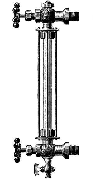
Lunkenheimer Water Gauge.
BLOW OFF VALVE.
The Blow Off Valve is an angle or globe valve attached to the lower part of a boiler for the purpose of blowing off the sediment accumulated by the use of impure water, and should be used more or less frequently according to the condition of the water used, but never less than once a week. There is also a surface blow off which is attached to the boiler at about the safe water level for the purpose of blowing off the scum which accumulates on top of the water. This scum should be blown off once or twice a day.
GAUGE COCK.
A Gauge Cock is a stop cock attached to a boiler to ascertain the height of water in the boiler. There are generally two and sometimes three gauge cocks attached to a boiler. The lower one enters the boiler as low down as it is deemed safe to allow the water to get, while the upper one enters the boiler sufficiently high to avoid getting too much water. Where three gauges are used, the middle one enters the boiler at about the proper water level. They should be opened frequently to keep them free from corrosion, being sure to close them tightly to prevent leaking.
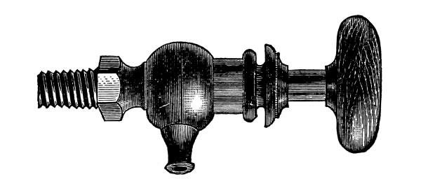
Lunkenheimer Gauge Cock.
CYLINDER COCKS.
Cylinder Cocks are used in connection with the cylinder to allow the water accumulated by the condensing of steam in the cylinder to escape, and should be opened every time the engine is started or stopped. This should never be neglected, as great damage may be caused by the breaking of the follower plate or cylinder head. They should also be left open when engine is shut down, and at night in cold weather to prevent freezing and the consequent damage.
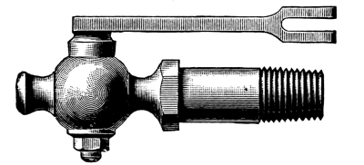
Lunkenheimer Cylinder Cock.
CHECK VALVE.
A Check Valve is the valve on the feed pipe between pump or injector and the boiler. The check valve is so constructed that the pressure of the feed water from the pump or injector lifts the valve from its seat and the water passes into the boiler. Immediately after the pressure from the pump or injector is released, the pressure from the boiler closes this valve and prevents the water from being forced back into the pump or injector. There are two check valves used in connection with a pump, one on suction, the other on deliver pipe.
Q. How can check valves that get stuck open be closed?
A. By simply tapping them slightly with a light hammer.
Q. Should this be practiced?
A. No, when they stick at all they should be opened and thoroughly cleaned as soon as pressure can be shut off.
COMPRESSION GREASE CUP.
Compression grease cups are used extensively on engines for lubricating the crank-pin and wrist-pin, also pillow block bearings for crank shaft; in fact this method of lubrication for all kinds of bearings and journals is becoming universally adopted.
In construction the Besly Bonanza Cup is simple and durable. The outer casing is threaded and fits tightly over the bottom part of cup. After the cup has been put in place, remove the top part, fill it with Helmet oil or grease and screw it on the lower part for two or three threads. The cup is then in working order.
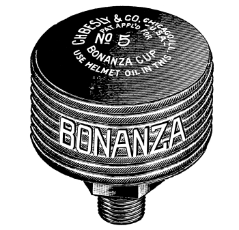
To insure a plentiful supply of grease to the journal or bearing, all that is necessary is to give the top part of cup an occasional turn.
C. H. Besly & Co.’s Helmet Solid Oil is for use in compression cups, and is a perfect lubricant, in fact it is said to be the best.
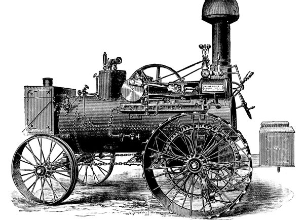
MINNEAPOLIS TRACTION ENGINE.
The engine is supplied with a return flue, straw, wood and coal burning boiler. The shell of the main flue is cylindrical in shape, but tapers toward the front end. By this arrangement the return flues can be set lower at the front end, which it is claimed has some advantage in protecting front end of flues when ascending steep hills.
The steam used is superheated by being conducted through a pipe which extends from the top of the dome on the inside of boiler through the front head and smoke stack to the steam chest.
The engine is of the Side Crank, Side Gear style, the frame of which is the girder pattern with bored guides, and has an overhanging cylinder attached to one end, and contains the pillow block bearing at the other.
It is fitted with the Woolf Valve Gear for reversing, Friction Clutch, Cross-head Pump, Injector, Syphon for filling water tank on front end, and a large Foot Board with Tool Boxes attached. The wheels are of steel, and the traction or drive wheels are furnished with malleable mud cleats extending diagonally across the entire width of tire.
The boiler is safe with proper care, economical in fuel, and the engine moves over the road rapidly. Although simple in its general construction, it has all the appliances and fittings necessary on a traction engine.
Minneapolis Traction Engine.