VOLUME IV PART 2 (continued 3)
Reading edition
Elasmothe´rium, an extinct genus of Mammalia, found in the post-Pliocene strata of Europe, comprising animals of great size allied to the rhinoceros, and having probably one large horn and a smaller nasal horn.
Elastic Bitumen, Elaterite, or Mineral Caoutchouc, an elastic mineral bitumen of a blackish-brown colour, and subtranslucent. It has been found at Castleton, in Derbyshire.
Elasticity, the property in virtue of which bodies resist change of volume or of shape, and tend to regain their original bulk or shape when the deforming forces are removed. Solids possess elasticity of volume and of shape. Liquids and gases have elasticity of volume; they resist compression, but offer only a transient resistance to change of shape (see Viscosity). The elasticity of a gas is measured by the pressure to which the gas is subjected, if there is no change of temperature. When a gas is compressed suddenly, it has a greater elasticity on account of the rise of temperature which takes place. Liquids are less compressible than gases; water is compressed by about 1 part in 20,000 when the pressure on it is increased by one atmosphere. A knowledge of the elastic properties of solids is of importance in all branches of applied mechanics. Homogeneous solids offer definite resistance to compression, twisting, stretching, and bending, and this resistance is expressed by a number called a modulus. Let the deforming force be reckoned per unit of area, e.g. a pressure in tons per square inch; this is called the stress. The unital deformation produced by the stress is called the strain, for example, compression per unit of volume. The modulus is obtained by dividing the stress by the strain; if this is done with the above example, the ratio will give the bulk modulus. When the applied forces cause change of shape without change of volume, the ratio of stress to strain is called the shape modulus or the rigidity of the material. This property is brought into play when mechanical power is transmitted by means of shafting. Young's modulus is employed in the cases of stretching and bending. It is given by the ratio stretching force per unit area to stretch per unit length. In 1678 Hooke stated the law that stress is proportional to the strain which it causes. This law is found in practice to be true for metals within a certain range of stress which lies below the elastic limit. If the stress is increased beyond this limit, the material begins to give way, and permanent change of shape or volume takes place. In the processes of riveting and wire-drawing, the material is purposely strained beyond the elastic limit, whilst the correct working of a spring balance requires that the spring should never be overstrained. When metals are subjected to frequently repeated stresses, they undergo a weakening and are said to become fatigued, and are liable to give way under a smaller stress than would otherwise cause fracture. The speed with which sound waves are transmitted through a material depends on the elasticity of the material; such compressional waves in water have been employed by the Roumanian engineer, Constantinescu, to transmit power by means of water-pipes.
Mathematical Theory.—Consider an elastic body at rest and free from strain. Let the body be subjected to forces, fulfilling the ordinary statical conditions of equilibrium, and therefore not tending to give the body any motion of translation or rotation as a whole. The particles of the body will move very slightly relative to each other; in other words, a system of strain will be set up in the body. To maintain this strain a definite system of stress is necessary. The problem for the mathematical theory is to determine the state of strain and stress at every point of the body when the applied forces are given. These applied forces may either be body forces (of which practically the only example is weight), or surface forces; the latter are pressures or tractions, and are defined by their directions and amounts per unit area. It is first of all necessary to show how strain and stress can be specified mathematically.
Strains.—If x, y, z are the co-ordinates of a point in the unstrained body, and if this point is displaced to (x + u, y + v, z + w) when the straining forces are applied, then u, v, w, which are supposed to be very small, are called the component displacements at (x, y, z). It is clear that if u, v, w were constant, the body would simply be displaced without strain. The state of strain can in fact be shown to depend on the first derivatives of u, v, w with respect to x, y, z. The strain round any given point consists simply of three stretches parallel to a certain set of three mutually perpendicular directions. These directions vary from point to point, so that this specification of the strain is inconvenient for calculations. A suitable method depends on the fact that the strain is known round a point when we know the values of the six quantities
du , dv , dw , dw + dv , du + dw , dv + du ,
dx dy dz dy dz dz dx dx dy
at the point. These are called the components of strain at (x, y, z). The first three are stretches parallel to the axes, the other three are shearing strains. We may get an idea of the nature of these strains from two simple typical cases. 1. Let u = ex, v = 0, w = 0. This makes du/dx = e, and the other five strains zero. But we see that the displacement of every particle is perpendicular to the yz plane, and proportional to its distance from that plane. Every line parallel to the axis of x is therefore elongated by a definite fraction of its original length, the value of this fraction being e, which is du/dx. The strains du/dx, dv/dy, dw/dz are therefore stretches parallel to the axes. 2. Let u = 0, v = cz, w = 0. This gives dv/dz + du/dy = c, and the other five strains zero. The displacement of every particle is parallel to the axis of y, and proportional to its distance from the plane xy. The strain is therefore a slide, or shear of planes parallel to xy in the direction of the axis of y.
Stresses.—To specify the stress round a point (x, y, z), consider a small plane area through the point. The material on one side of this acts on the material on the other side with a certain force whose components parallel to the axes are F, G, H, say, per unit area. If we know F, G, H for every orientation of the small plane area, the state of stress round (x, y, z) is defined. But it is easy to show, as below, that we can find F, G, H for every area if we know them for areas parallel to the co-ordinate planes. We are thus led to the specification of the stress round (x, y, z) by the six components of stress, xx, yy, zz, xy, xz, yz; where xy, for example, means the force per unit area parallel to Ox exerted on a plane perpendicular to Oy by the material on the positive side of that plane on the material on its negative side. Thus e.g. the components of the force per unit area exerted across the yz plane through (x, y, z) by the material on the positive side of that plane are xx, xy, xz. It is important to note that xy = yx. This is easily proved by considering the equilibrium of a small rectangular volume of the material round (x, y, z) as centre, with its edges parallel to the axes; if xy were not equal to yx, there would be a residual couple in the plane xy.
Relations between the Strains and the Stresses.—When the strains are known, the stresses can be found from a generalized Hooke's law, which can be deduced from the principle of energy, combined with consideration of symmetry. If the solid is isotropic, i.e. is symmetrical in its elastic properties in all directions round a point, the relations between stress and strain are of the form
xx = λ( du + dv + dw ) + 2μ du ,
dx dy dz dx
yz = μ( dw + dv );
dy dz
the values of the other four components of strain can be written down from symmetry. Here λ and μ are constants, each being a modulus of elasticity. In particular μ is the shape modulus or the rigidity, already referred to. The Young's modulus and the bulk modulus can easily be found in terms of λ and μ.
Equations of Equilibrium in Terms of the Stresses.—A rectangular element dx, dy, dz, of the body is held in equilibrium by the body force, and the tractions on its faces arising from the stress. The tractions per unit area, parallel to the axis of x, on the six faces, are: on the plane x, -xx; on the plane x + dx, xx + (d/dx xx)dx; on the plane y, -xy; on the plane y + dy, xy + (d/dy xy)dy; and similarly for the plane z. Let the force acting on the mass of the body, such as its weight, be (X, Y, Z) per unit mass, and let ρ be the density. By equating the sum of the x components of all the forces to zero, we get
dxx + dxy + dxz + ρX = 0;
dx dy dz
Similarly dxy + dyy + dyz + ρY = 0,
dx dy dz
and dxz + dyz + dzz + ρZ = 0.
dx dy dz
The Surface Tractions in Terms of the Stresses.—Draw a small tetrahedron round (x, y, z) with its faces perpendicular to the axes and to the direction (l, m, n), and consider the equilibrium of this small body. Let F, G, H be the components per unit area of the force on the plane whose direction cosines, drawn outwards, are l, m, n. If A be the area of the face perpendicular to (l, m, n), we get, by resolving parallel to Ox,
F·A = xx·lA + xy·mA + xz·nA. Hence F = lxx + mxy + nxz, and similarly G = lxy + myy + nyz, H = lxz + myz + nzz.
If (x, y, z) is a point at the surface of the body, and l, m, n are the direction cosines of the outward normal at that point, these values of F, G, H are the component of the force that must be applied from outside to the surface at (x, y, z) to maintain the state of stress.
The Equations connecting the Displacements and the Applied Forces.—By using, in the equations of equilibrium, the values of the stresses in terms of the strains, we find the body equations of equilibrium in terms of displacements,
μ ( d2u + d2u + d2u ) + (λ + μ) d ( du + dv + dw ) + Xρ = 0,
dx2 dy2 dz2 dx dx dy dz
with two similar equations.
The surface equations of equilibrium can also be written down at once by substituting the values of stresses in terms of strains in the expressions for F, G, H given above.
The Problem of Equilibrium.—To find the strain under given forces we have to solve the body and surface equations of equilibrium, when X, Y, Z and F, G, H are given. This problem has not been completely solved except in a few cases. It was solved by Lamé and Lord Kelvin for a solid or hollow sphere; it has also been solved for an infinite solid bounded by two parallel planes, or by a circular cylinder. Many particular solutions, however, are known for bodies of other shapes. Some of these solutions are of great practical value, e.g. St. Venant's solutions for the torsion and flexure of prisms. For bodies in which one or two dimensions are small, i.e. for thin plates and shells, and for thin rods, approximate theories have been given, which are partly deduced from the above exact equations, and partly from plausible hypotheses, a complete treatment based on the exact equations being in most cases impracticable.
The Problem of Vibrations.—When a body is vibrating, the mass acceleration parallel to Ox of the particle at (x, y, z) is ρ dx dy dz d2u/dt2. The equations of vibration are therefore found by writing - d2u/dt2 instead of X, in the first body equation of equilibrium, and similarly with the others. The surface conditions will usually be that F, G, H are zero. The problem has been completely solved by H. Lamb for a solid or hollow sphere. For the elastic solid theory of the luminiferous ether, see Ether; for some practical solutions of the general equations of equilibrium, see Strength of Materials.—Bibliography: A. E. H. Love, Mathematical Theory of Elasticity; Lord Kelvin and Tait, Natural Philosophy; Todhunter and Pearson, History of Elasticity and Strength of Materials.
El´ateridæ, the name of a family of beetles, remarkable for their ability to throw themselves to a considerable height in the air, when placed on their back, by a vigorous muscular movement. Hence their names of springing-beetles, click-beetles, skip-jacks, &c. When alarmed, the elater counterfeits death. Flowers, grass, and decaying wood are the habitations of these animals, which are almost always found singly. The larvæ are often very injurious to vegetation, especially those which devour the roots of herbaceous plants (as in the genus Agriōtes), and are known from then slenderness and hardness as wire-worms. The fireflies of America belong to the family. In these a pair of luminous organs is found on the thorax, while there is a third on the under side of the base of the abdomen. The Pyrophŏrus noctilūcus, called cucujos in Brazil, is used as a personal ornament by ladies. The largest species of the genus Elater, the Elater flabellicornis, is 2½ inches in length.
Elate´rium, a substance obtained from the fruit of the squirting or wild cucumber (Ecballium agreste). The juice of the unripe fruit, when expressed and allowed to stand, deposits elaterium as a green sediment with an acrid taste, a faint odour, and powerful cathartic properties. It is a violent purgative, and is poisonous, but its action is not constant. The active principle in it is called elaterin.
Elba (Lat. Ilva), a small island in the Mediterranean, in the province of Livorno (Leghorn), Italy, separated from the mainland by the Strait of Piombino, about 6 miles wide. The island is 18 miles long and from 2½ to 10½ miles broad, and is traversed by mountains rising to a height of over 3000 feet. It is rich in iron, marble, granite, salt, &c.; and iron ore is exported. Excellent wine and fruits are produced. It has two seaports—Porto-Ferrajo (the capital) and Porto-Longone. The Treaty of Paris in 1814 erected Elba into a sovereignty for Napoleon, who resided in it from 4th May, 1814, to 26th Feb., 1815, when he escaped and landed at Cannes on 1st March. After Napoleon's departure the island was restored to Tuscany, which became part of Italy in 1860. Pop. 30,450.
Elbe (elb; Ger., pronounced el´be; Lat. Albis; Bohem. Labe), an important river in Central Europe. It rises on the south-west slopes of the Schneekoppe or Snowcap, one of the Riesengebirge, between Bohemia and Silesia. From this point it flows nearly due south into Bohemia for about 50 miles, when it turns to the west, and after about 40 miles takes a general north-north-west direction till it falls into the North Sea, intersecting Saxony and a considerable portion of Prussia. The finest scenery of its valley is in the Saxon Switzerland. Its length is 725 miles; drainage area, 56,865 sq. miles. The principal affluents are: on the right, the Iser, Schwarz-Elster, and Havel; on the left, the Alder, Moldau, Eger, Mulde, and Saale. In the lower part of its course the river divides into several arms, which unite again about 5 miles below Hamburg. It is more or less navigable for about 525 miles, but its estuary is much encumbered with sand-banks. In 1870 its navigation was declared free from Hamburg to Melnik in Bohemia. The North Sea and Baltic ship canal connects its estuary with Kiel Bay, and there are other important connected canals. It is well stocked with fish.
Elberfeld (el´bėr-felt), a town of Rhenish Prussia, in the government of and 15 miles east of Düsseldorf, on both sides of the Wupper, enclosed by lofty hills. Taken with Barmen it stretches along the Wupper valley for about 7 miles. The old streets are narrow and irregular, but the newer quarters are well built. It is a great seat of manufacturing industry, among its leading products being cottons, woollens, silks, velvet, mixed textile goods, buttons, ribbons, lace, yarns, thread, carpets, aniline dyes, iron and steel, machinery, pianofortes, and paper. Calico-printing, dyeing, and bleaching are very extensively carried on. It has given its name to a system of poor relief, combining organized voluntary effort and individual treatment. Pop. 170,195.
Elbeuf (el-beuf), a town of France, department of Seine-Inférieure, 11 miles S.S.W. of Rouen, in a valley on the left bank of the Seine, connected by two bridges with St. Aubin on the opposite side of the river. It is an important centre for the production of woollen manufactures, chiefly of lighter cloths and fancy goods, and is also an entrepôt for the finer and heavier cloths of Louviers and Sedan. It communicates by steamers with Paris, Rouen, and Havre. Pop. 19,240.
Elbing, a seaport town of West Prussia, on the Elbing, near its entrance into the Frische-Haff. It was once a flourishing Hanse town, and is still a place of considerable industry and trade, the manufactures including iron goods, machinery, brass and tinplate goods. It has also shipbuilding yards. Pop. 58,636.
Elburz, a lofty mountain range extending over Northern Persia, parallel with and overlooking the Caspian. Highest peak, Mt. Demavend, 19,400 feet; average height, 6000 to 8000 feet.
Elcesaites (el-ses´a-īts), a sect of Gnostics which arose in the reign of Trajan about the beginning of the second century. They were a branch of the Essenes, and resembled the Ebionites. A Jew, named Elxai, or Elkesai, is their reputed founder.
Elche (el´chā), a town of Spain, in the province and 14 miles W.S.W. of Alicante, on the left bank of the Vinalopo, surrounded by palm trees. It contains various Roman remains, a fine church, and a town house of the fifteenth century. Chief industry, the culture of dates. Each summer, from the 13th to the 15th of August, an interesting fête is held at Elche, and a fourteenth century liturgical drama (The Representation of the Assumption of Our Lady St. Mary) is performed. Pop. 27,620.
Elchingen (el´hing-en), Ober and Unter, two villages of Bavaria, on the left bank of the Danube, about 3 miles apart and 8 miles north-east of Ulm. In 1805 Marshal Ney defeated the Austrians at Ober Elchingen, and won for himself the title of Duke of Elchingen.
Common Elder: Foliage, Inflorescence, and Fruit
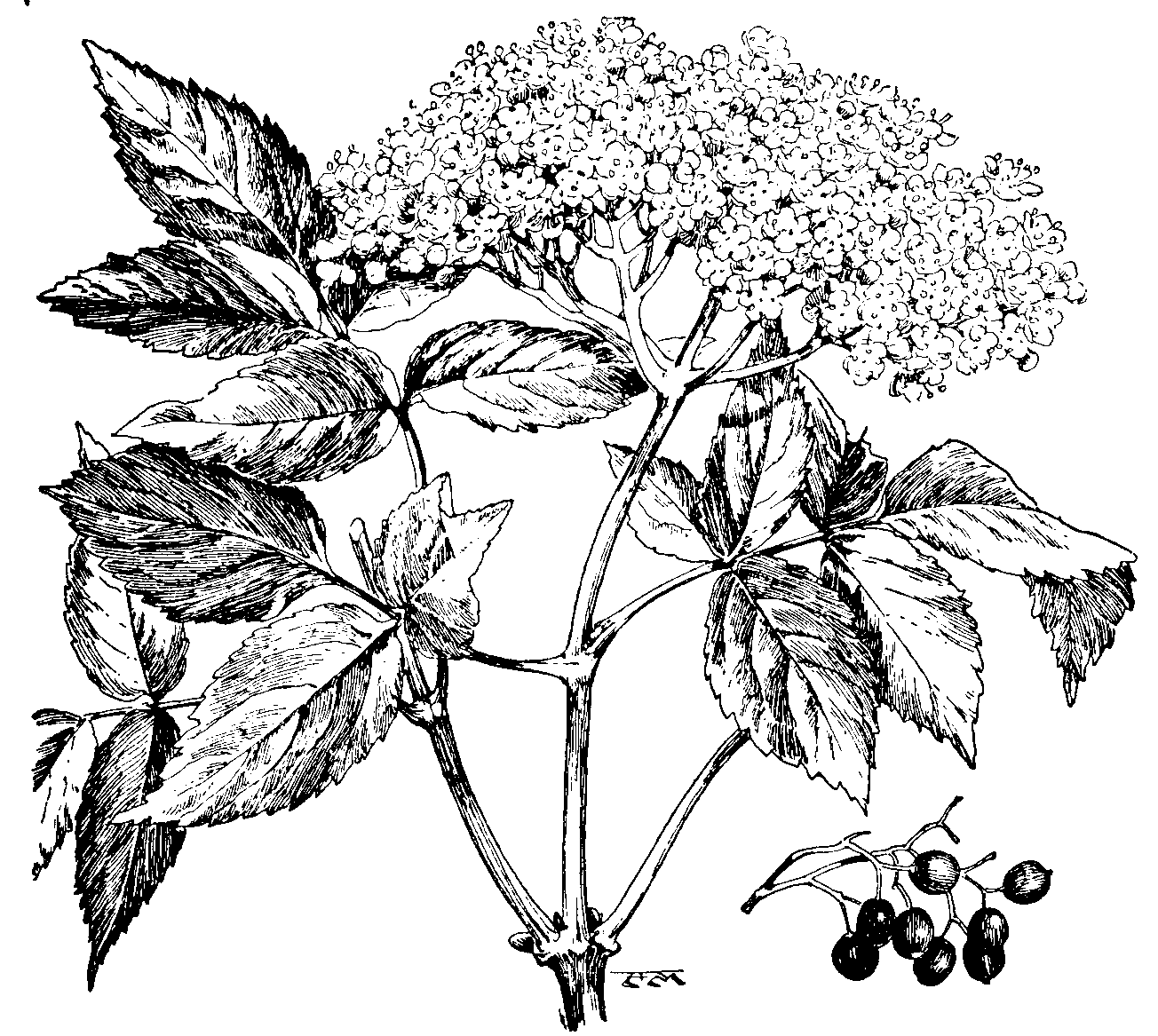
Elder, a name given to different species of the genus Sambūcus, nat. ord. Caprifoliaceæ. These are small trees or shrubs, with opposite and pinnated leaves, bearing small white flowers in large and conspicuous corymbs, small berries of a black or red colour, and bitter and nauseous leaves possessing purgative and emetic properties. The wood of the young shoots contains a very large proportion of pith. The common elder of Britain (S. nigra) is a wild shrub or small tree, distinguishable by its winged leaves, its clusters of small, cream-white flowers, and the small black berries by which these are succeeded, and from which a kind of wine is sometimes made. The dwarf elder or danewort (S. Ebulus) is also found in many parts of Britain, and was popularly supposed to have sprung from the blood of the Danes. Two species inhabit North America: S. canadensis, a common plant from the 49th to the 30th parallel of latitude, the berries of which are black and have a sweet taste; and S. pubescens, which bears red berries, and inhabits Canada, the northern parts of New England, and the Alleghany Mountains. Elder wood is yellow, and in old trees becomes so hard that it is often substituted for box-wood. Its toughness, also, is such that it is made into skewers and tops for fishing-rods. The light pith is utilized for balls for electric experiments, and various ointments, drinks, and medicinal decoctions are made from the bark, leaves, flowers, and berries.
Elders, persons who, on account of their age, experience, and wisdom, are selected for office, as, among the Jews, the seventy men associated with Moses in the government of the people. In the modern Presbyterian Churches elders are officers who, with the pastors or ministers, compose the consistories or kirk-sessions, with authority to inspect and regulate matters of religion and discipline in the congregation. As a member of the kirk-session the elder has an equal vote with his minister, and as a member of the higher Church courts, when delegated thereto, he has a right to discuss and vote on all matters under discussion in the same manner as the clergy themselves. In the Mormon Church the elder is an officer whose duty it is "to preach and baptize, to ordain other elders, to bless children, and to take the lead at all meetings". Among the Shakers there are four elders, two men and two women, in each congregation.
Eldon, John Scott, Earl of, Lord Chancellor of England, born in 1751 at Newcastle-on-Tyne, died in London, 13th Jan., 1838. His father was a coal-dealer and public-house keeper of means, and John was educated with his brother William (afterwards Lord Stowell) at Newcastle, and at Oxford, where he obtained a fellowship. He was called to the Bar in 1776, and in 1782 was made King's Counsel. Next year he entered Parliament, supported Pitt, and was made Solicitor-General, and knighted. In 1792 he purchased the estate of Eldon. In 1793 he became Attorney-General, and in 1799 was created Chief Justice of the Court of Common Pleas, and raised to the peerage and the House of Lords by the title of Baron Eldon. On the accession of the Addington ministry he became Lord Chancellor (1801), and retained this post under the subsequent administration of Pitt until the death of the latter in 1806. A year later, however, he resumed the chancellorship under Liverpool, and held it without break for twenty years. In 1821 he was created an earl by George IV. On the accession of the Canning ministry in 1827 he resigned the chancellorship, and never again held office. As a lawyer he was a master of English jurisprudence; as a politician he was opposed to reform, and by no means free from the charge of servility and intrigue.
El Dora´do, a country that Orellana, the lieutenant of Pizarro, pretended he had discovered in South America, between the Orinoco and Amazon Rivers; and which he named thus on account of the immense quantities of gold and precious metals which, he asserted, he had seen in Manoa, the capital of the country. The term El Dorado was first applied to a South American tribal king who was said to cover his body annually with gold-dust. It now designates any place abounding in gold, or offering opportunities for the acquisition of sudden wealth.
Eleanor Crosses (el´i-nor), memorial crosses erected on the spots where the bier of Eleanor, the wife of Edward I, rested on its way from Grantham to Westminster. Twelve were erected, but only three, those of Northampton, Geddington, and Waltham, remain.
Eleat´ic School, a Grecian philosophical sect, so called because it originated in Elea (Lat. Velia), a town of Magna Græcia (Southern Italy), of which also three of its most celebrated teachers, Parmenides, Zeno, and Leucippus, were natives. The founder was Xenophanes of Colophon, who came to Elea late in life, bringing with him the physical theories of the Ionian school, to which he added a metaphysic. The two schools soon drifted widely apart, especially in respect of method. In opposition to the physical philosophy of the Ionian school, and also the doctrine of Heraclitus, who taught that everything is flux, the Eleatic philosophers asserted that change and difference are only empty illusions, and that the only true reality is changeless being. Starting from the observation of external nature, the Ionians endeavoured to discover some elementary principle, as water, air, fire, or a combination of elements, by the action of which the phenomena they observed might be accounted for. The Eleans made the abstract idea of Being or God, deduced from the contemplation of the Universe as a whole, their starting-point. Their reasonings sometimes led them to deny the reality of external phenomena altogether.
Elecampane (el-i-kam-pān´; Inŭla Helēnium), a plant of the nat. ord. Compositæ, found in Britain and other parts of Europe, and in Asia. It is 3 or 4 feet high; the radical leaves are often 2 feet and more in length; the flowers are large and yellow; the root, which is perennial, possesses a bitter camphor-like taste. It was formerly much used as a stimulant for all the secreting organs, and in tuberculosis on account of the germicidal action of the bitter principle (helenin) which it contains.
Election, in theology, the doctrine that God has from the beginning elected a portion of mankind to eternal life, passing by the remainder. It is founded on the literal sense of certain passages of Scripture, and has been amplified by the labours of systematic theologians into a complete and logical system. It dates in ecclesiastical history from the time of Augustine; but Calvin has stated it so strongly and clearly in his Institutes that it is generally associated with his name.
Election, in politics, the selection by voting of a person or persons to occupy some post or office. The most important elections are those of the members of the legislative assemblies of the different countries, and as to the manner in which these are carried out strict laws are in force. In such elections voting by ballot is now general. The chief forms of election in Britain are parliamentary and municipal elections, in both of which the basis of the suffrage (or right of voting) is the payment of poor rates. Members of Parliament formerly required a property qualification in England and Ireland; but this restriction, which never existed in Scotland, has been abolished. In both parliamentary and municipal elections the ballot has been in operation since 1872. For the prevention of bribery and corrupt practices many Acts have been passed, of which that now in operation came into force in Oct., 1883, and has been annually renewed. By it persons convicted of treating, bribery, personation, and undue influence are liable to imprisonment with hard labour, and to disqualification in respect of the franchise and public offices. It also imposes many limitations with regard to the number of assistants and committee-rooms, and the use of conveyances. By the Reform Act of 1918, the maximum expenditure for campaign purposes during parliamentary elections is to be sevenpence per elector in county constituencies, and fivepence per elector in boroughs. By this Act the cost of registration is paid half out of local rates, and half by the State. At election times the returning officer's expenses are to be paid by the Treasury. Under the provisions of the Ballot Act the returning officer is required, in the case of a county election, to give notice of an election within two days after that on which he receives the writ; or in the case of a borough election, to give notice on the day on which he receives the writ, or at the latest on the day following. In county or district borough elections the nomination must take place within ten days of the receipt of the writ, at least three clear days, however, being allowed to elapse between the first public notice and the day of nomination. In ordinary borough elections the candidate must be nominated not earlier than the third day after public notice, and not later than the fourth day after that on which the writ is received. A candidate is nominated in writing, with the signatures of a proposer, seconder, and eight other electors, all registered in the constituency to be represented. In the event of there being more candidates than vacancies, the returning officer adjourns the election for the purpose of taking a poll. The polling must take place not less than two or more than six clear days after the day of nomination, if it be a county or district borough election; in the case of an ordinary borough, it must take place not more than three clear days after nomination, Sundays, Christmas Day, &c., not being counted as days. Where the votes for rival candidates are equal, the returning officer, if registered in the constituency, may give the casting-vote. If he decline to do so, a scrutiny is demanded, which usually results in certain deductions on the ground of spoiled papers, disqualified voters, &c., sufficient to give one candidate priority. In elections for the school boards the cumulative system of voting is employed (see Cumulative Vote).—Cf. C. Seymour and D. P. Frary, How the World Votes.
Elector (Ger. Kurfürst, 'electoral prince'), the title of certain princes of the Holy Roman Empire, who had the right of electing the emperors. In the reign of Conrad I, King of Germany (912-918), the dukes and counts became gradually independent of the sovereign, and assumed the right of choosing future monarchs. In the thirteenth century the number of these electors was seven—the Archbishops of Mainz, Cologne, and Trèves, the King of Bohemia, the Count Palatine, the Duke of Saxony, and the Margrave of Brandenburg. In 1648 an eighth electorate was created to make room for Bavaria, and Hanover was added as a ninth in 1692. The votes of the Palatinate and of Bavaria were merged in one in 1777. In 1802 the two ecclesiastical electors of Cologne and Trèves were set aside, and Baden, Würtemberg, Hesse-Cassel, and Salzburg declared electorates; so that there were ten electors in 1806 when the old German Empire was dissolved.—Cf. Viscount Bryce, The Holy Roman Empire.
Electrical Fishes, a name given to fishes possessing the property of communicating an electric shock when touched with the hand or any electric conductor. One of the best known is the electric eel (Gymnōtus electricus), a native of South America. It is of nearly equal thickness throughout; head and tail obtuse; ordinary length, 3½ to 4 feet. The seat of the four electrical organs is along the under side of the tail, and they are said to possess the power of knocking down a man, and of painfully numbing the affected limb for several hours after the shock. After a few discharges, however, the faculty of producing a shock is impaired, and an interval of rest is required for a new storage of force. Similar but less-marked powers are possessed by an African cat-fish (Malapterurus electricus), in which the electric organ invests the entire body as a sort of jacket under the skin. Still feebler in this respect are the electric rays, of which the best known (species of Torpedo) are native to the Mediterranean, Red Sea, Atlantic, and Pacific Oceans. Here the electric organ consists of a large mass on each side of the front part of the body.
Electrical Measuring Instruments, the name given to instruments which measure electric power, energy, voltage, or current. The majority of such instruments are current-operated. Thus, with the exception of electrostatic voltmeters, all voltmeters are really current measuring instruments; but since this current is made to be proportional to the P.D. between the voltmeter terminals, the scale reading is proportional to the voltage being measured. One and the same instrument may be used as an ammeter or as a voltmeter, by providing it with shunts for use as an ammeter, and series resistances for use as a voltmeter. If the current to be measured is large, the shunt will have a very low resistance compared with that of the instrument, so that only a small fraction of the total current passes through the instrument. Similarly, when a large P.D. is being measured, the series resistance will have a very high value, so that the current through the instrument may not exceed that which gives full-scale reading. By using shunts or series resistances of different values, different ranges can be given to the instruments.
In addition to the types already described (see Ammeter), there is a class depending on the mutual action of current-carrying conductors placed near one another. This type is largely used in alternating-current work. It is also specially suitable for power measurements, and practically all wattmeters work on this principle. The Siemens Dynamometer was the first instrument of this type.
The Kelvin Standard Balance is a special form of dynamometer, in which the mechanical turning-moment due to weights on a beam is balanced by the electrical turning-moment due to currents in fixed coils and in coils attached to the ends of the beam. The electrostatic voltmeter mentioned above is the only instrument which is operated by a P.D. instead of a current. In it a moving vane is attracted into a fixed pair of quadrants; or a set of vanes is attracted into a set of quadrant cells.
The majority of electricity meters are of the motor type, i.e. a disc is driven by motor action at a speed which is proportional to the power passing through the meter. The disc spindle engages with gearing which drives the pointers on a set of dials recording the energy units. There are also meters depending on electrolytic action (Wright meter); or on the difference in period between two pendulums, one of which is controlled by the load current (Aron meter).
Electric Battery, a group of primary or secondary cells, suitably arranged for the purpose of producing an electric current. Primary batteries consisting of a few cells are commonly used for intermittent work where a relatively small current is required, e.g. for electric bells. If a larger current is necessary, especially if it has to be maintained over a considerable period, a battery of secondary cells is used. Such batteries are commonly used for country house lighting. Very large batteries, used either alone or in conjunction with automatic reversible boosters, are frequently employed in public electric supply systems.
The name electric battery was originally given to an arrangement of Leyden jars (see Leyden Jar), but is now applied only to cells, the Leyden-jar arrangement being called a Leyden-jar battery.
Electricity, the name given to the ultimate cause of electrical phenomena. The laws governing these phenomena are well known, but the actual nature of electricity has not yet been fully revealed, although much light has been thrown on the subject by recent researches. (See Electron.) Although the practical applications of electrical phenomena have all been developed within the last fifty years, the production of an electric charge by friction, as demonstrated by the power of rubbed amber to attract light bodies, was observed by a Greek philosopher as long ago as 600 B.C. The Greek name for amber, ηλεκτρον (electron), is the root from which our word electricity is derived. Friction was the only artificial source of electricity known until Galvani, near the close of the eighteenth century, accidently obtained it by the contact of two metals with the limbs of a frog; and Volta, developing Galvani's discovery, invented the first galvanic or voltaic battery.
The discovery by Faraday in 1831 of the principle of the production of an electromotive force by the motion of a conductor in a magnetic field, laid the foundation for the development of the electric generator (q.v.), and thus of modern electric power supply.
The study of electrical phenomena is conveniently divided into two branches, one dealing with stationary charges of electricity (electrostatics), the other with electric currents (current electricity).
Electrostatics.—If a pair of ebonite rods be electrified by friction with flannel, then by suspending the one rod and presenting the other to it, it is easily demonstrated that a mutual mechanical force of repulsion exists between them. If now a glass rod be electrified by friction with silk, it will be found that it attracts the suspended electrified ebonite rod. These experiments reveal the facts that electric charges may be of two opposite kinds, and that like charges repel one another, while unlike charges attract one another.
The charge produced on glass by friction with silk is called positive; that produced on ebonite by friction with flannel is called negative. The kind of charge produced depends not merely on the material rubbed, but also on the material of the rubber. Thus a warm dry glass rod becomes negatively electrified when rubbed with fur. The rubber always becomes electrified with a charge of the opposite kind to that produced on the material rubbed, and these two charges are equal in amount. All bodies may be electrified by friction, but those which allow a free movement of the charge over them (such bodies are called conductors, to distinguish them from insulators, which do not allow this free movement) must be held by an insulating handle, or else the charge will be removed as quickly as it is produced.
Coulomb proved that the magnitude of the mutual mechanical force exerted between two charged bodies depends on the amounts of the charges and the distance between them. Faraday called attention to the influence of the medium in which the charges are placed. Thus if two charges of q1 and q2 units respectively are placed d centimetres apart in a given medium, the mechanical force f in dynes exerted between them is given by the equation f = (q1q2)/(Kd2), provided the dimensions of the bodies on which the charges are concentrated are small in comparison with d. The coefficient K is called the dielectric constant of the medium, and its value is taken as unity for air.
In accordance with this relationship, unit charge is defined as that charge which repels an equal and similar charge placed at a distance of 1 centimetre in air, with a force of 1 dyne.
If the medium surrounding a charged body be explored with a unit charge, a mechanical force varying in magnitude and direction from point to point will be found to act on the unit charge. In such a case, an electric field is said to exist in the medium.
The strength of the electric field at any point is defined as numerically equal to the mechanical force which would act on a unit charge placed in air (or more strictly in a vacuum) at that point. The direction of the electric field at any point is defined to be the direction of the mechanical force acting on a unit positive charge placed at that point.
It should be noted that the strength of the electric field and the mechanical force are numerically equal only when the dielectric constant of the medium is unity. Thus if F is the field strength, K the dielectric constant, and U the mechanical force acting on a unit charge, F = KU.
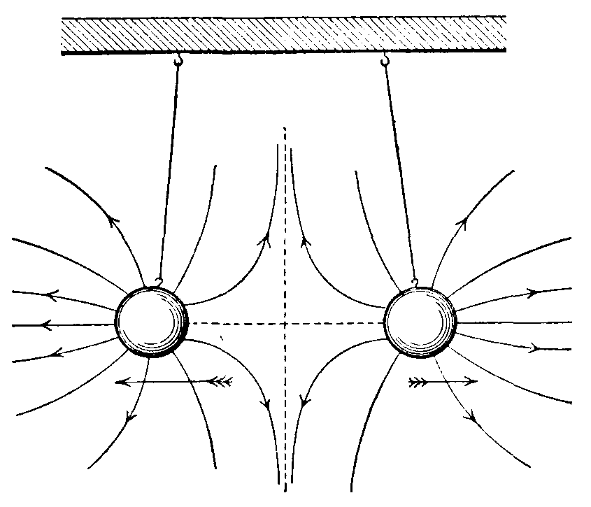
It is very convenient to represent an electric field by means of what are called lines of electric force. If lines are drawn, starting from a positive charge and ending on a negative charge, such that the tangent to the line at any point is the direction of the electric force at that point, these lines are called lines of electric force. They can be drawn in such a way that the strength of the electric field at any point is numerically equal to the number of lines of electric force passing through unit area surrounding that point (and taken at right angles to the direction of the force). The lines of electric force will thus completely represent the electric field.
Further, if the following properties are attributed to the lines of electric force, viz. (a) that a line of electric force tends to shorten itself as far as possible; (b) that lines of electric force mutually repel one another; then all the phenomena due to the presence of an electric field may be interpreted by the behaviour of the lines of electric force.
Figs. 1 and 2 show the lines of electric force in the space surrounding two charged spheres. Fig. 1 shows the case where the charges are opposite, fig. 2 the case where they are similar. In fig. 1 the attraction between the spheres may be thought of as due to the tendency of the lines of force to shorten themselves. Similarly, the mutual repulsion of the spheres in fig. 2 may be regarded as a consequence of the mutual repulsion of the lines of force.
Fig. 1
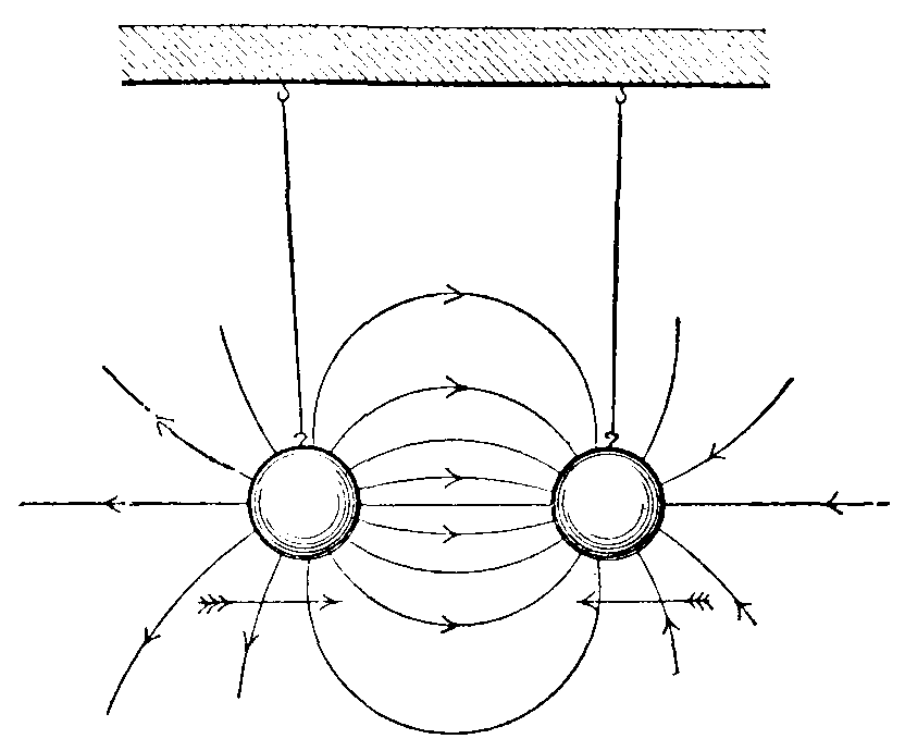
Fig. 2
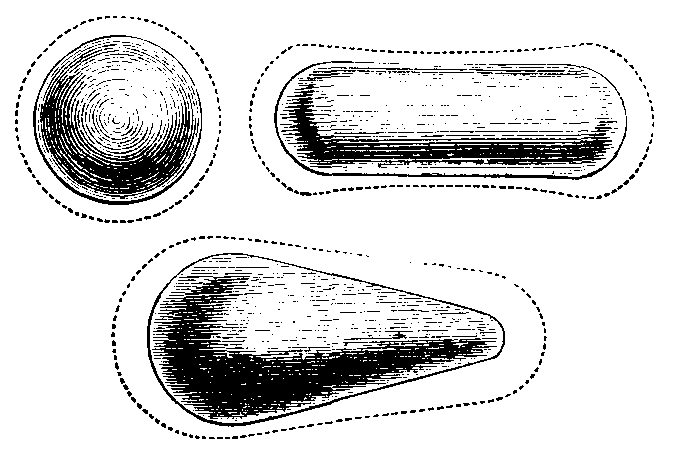
The distribution of a charge upon an insulated conductor isolated in space depends upon the shape of the conductor. If the conductor is spherical, the charge is uniformly distributed. If the curvature varies from point to point, the quantity of charge per unit area, or the electric surface density, will vary from point to point. The sharper the curvature is, the greater the surface density will be. In fig. 3 the distance of the dotted lines from the surface of the conductors is proportional to the surface density. These lines, therefore, give a graphical representation of the distribution of charge. In sharply pointed conductors nearly the whole charge will be concentrated at the pointed end. Owing to the large charge per unit area at the pointed part, particles of dust, water-vapour, &c., will be powerfully attracted, will become charged by conduction, and will then be powerfully repelled. In this way the original charge will be rapidly dissipated. This effect may be shown by keeping a sharply pointed conductor powerfully charged by an electric machine. The streaming of the particles from the point produces a wind which is sufficient to blow out the flame of a candle.
Fig. 3
Conductors which are intended to retain their charge for a long period must be smooth and polished, and the maximum curvature must be as small as possible. In lightning-conductors practical advantage is taken of this 'power of points' to dissipate a charge rapidly.
The distribution of the charge on a conductor is influenced by the presence of other conductors, whether charged or not. This is due to what is called electrostatic induction. If an uncharged insulated conductor B is brought near a charged conductor A, a charge of the opposite kind is induced on the parts of B nearer to A, and a charge of the same kind on the parts farther away from A. Since B was originally uncharged, these induced charges are equal in amount.
If B is now removed to a distance, the induced charges neutralize one another, and B returns to its original uncharged state.
While B is near A, let the induced charge of the same kind as the charge on A be neutralized by touching B with an earth-connected conductor, say the finger. On removing B to a distance, it will no longer be uncharged as before, but will have a charge of the opposite kind from that on A. B is now said to have been charged by induction.
It is instructive to view these phenomena in the light of the conception of lines of electric force. When B is brought up towards A, some of the lines of force associated with the charge on A, and originally linked to surrounding objects, will now, owing to the tendency of the lines to shorten themselves, be linked to B. At the same time an equal number of lines (of opposite direction relative to B) will link B to the nearest surrounding objects.
Since by definition a line of force starts from a positive charge and ends on a negative charge, the charge on the parts of B nearer to A will be of the opposite kind to that on A, but the charge on the part farther from A will be of the same kind as that on A. When the earth-connected conductor is brought near B, the lines formerly linking B to surrounding objects will link B to the earth-connected conductor. Finally, when the latter touches B, these lines shorten themselves indefinitely and disappear.
The attraction of light particles to a charged body is explained by electrostatic induction. The charge of opposite kind induced on the particle being nearer than that of the same kind, the particle is attracted. When it touches the charged body, the charge of opposite kind is neutralized, and the charge of like kind now left on the particle causes repulsion to take place. If the electrified body is an insulator, the neutralization of the charges only takes place slowly, and consequently it may be some time before the particle is repelled.
Fig. 4.—Induction, and Lines (or tubes) of Force
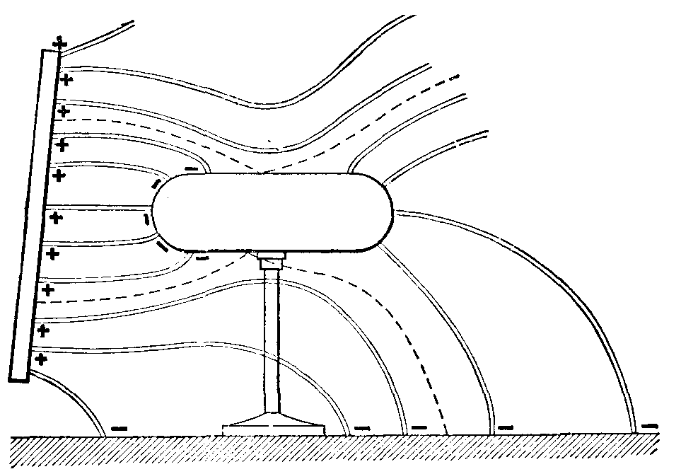
If two charged conductors be connected by a wire, in general it will be found that a flow of electricity from one to the other will take place. This flow is said to be due to a difference of electric potential between the two conductors. If no flow takes place, then the difference of potential is zero. Electric potential difference (the contraction P.D. is commonly used) is numerically equal to the work done in carrying a unit charge from the one conductor to the other. If the work is done against the electric forces, in moving a unit positive charge from A to B, then B is said to be at a higher potential than A. Although actually it is with differences of potential that we have always to deal, it is convenient in many cases to refer these differences to a zero, and speak of the potential at a point. The ideal zero of potential would be the potential at a point infinitely far removed from all electrified bodies. In practice it is convenient to regard the potential of the earth as zero. The potential at a point is then numerically equal to the work done in carrying a unit positive charge from earth to the point. The potential at every point on a conductor is obviously the same, for if it were not so, a flow of charge would take place and equalize the potential. If an insulated uncharged conductor be connected by a wire to a charged conductor, a flow of charge will take place until every point on both conductors is at the same potential. The quantity of charge which each conductor will then have depends on what is called the capacity of the conductor.
The capacity of a conductor is defined as the quantity of electricity with which it must be charged in order to raise its potential from zero to unity. Thus if Q be the quantity, V the potential, and C the capacity, we have C = Q/V. The potential of a conductor is, therefore, directly proportional to the charge upon the conductor, and inversely proportional to the capacity of the conductor.
The capacity of a conductor may be increased by placing close to it another conductor which is kept at zero potential. Such an arrangement is called a condenser. The Leyden jar (see Leyden Jar) is a well-known example of a condenser. The capacity depends not merely on the dimensions of the conductors and the distance between them, but also upon the nature of the dielectric separating them. The ratio of the capacity of a condenser with a given dielectric to the capacity it would have with an air dielectric, is called the specific inductive capacity of the dielectric. Numerically the specific inductive capacity of a dielectric is equal to the dielectric constant already mentioned.
Fig. 5.—Electrophorus
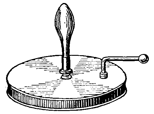
Fig. 6.—Wimshurst Machine
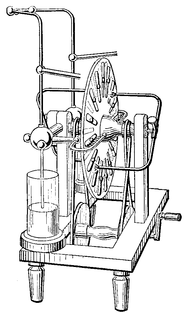
In the experimental investigation of electrostatic phenomena it is convenient to have appliances which will supply charges as they are required. The simplest appliance of this kind is the electrophorus, which consists of a disc of ebonite or other suitable material with a metallic base, and a metal disc of slightly smaller diameter having an insulating handle attached at right angles to its surface (see fig. 5). To use the electrophorus, the ebonite is given a negative charge by striking it with fur or flannel. The metal disc is then placed on top of the ebonite plate. Since the ebonite is an insulator, no general neutralization of the positive induced charge on the lower side of the metal disc can take place. The negative charge on the upper surface of the metal disc is then neutralized by touching with the finger. The disc is thus left positively charged. The disc is then lifted by the insulating handle, and the charge utilized as required. Theoretically speaking, this process may be repeated continuously without affecting the original charge on the ebonite plate, but in practice the ebonite has to be re-excited from time to time on account of the loss of charge by leakage. More elaborate appliances of many different forms have been used, but the only one of these electric machines, as they are called, which is now commonly employed is the Wimshurst machine. This machine consists of two circular plates of glass or ebonite carrying equal even numbers of tinfoil sectors symmetrically placed on their outer surfaces. A pair of brass arms carrying wire brushes, which simultaneously make contact with diametrically opposite sectors on each plate, is so arranged as to lie at an angle of about 45° to the horizontal, and to be at right angles to one another. A pair of combs is placed at each end of the horizontal diameter of the plates, so that the sectors pass close to the teeth of these combs. The combs serve as collectors, and are connected one pair to the positive pole, and the other pair to the negative pole of the machine. The general appearance of the machine is shown in fig. 6. The machine acts on the induction principle, and if kept warm and dry is self-exciting.
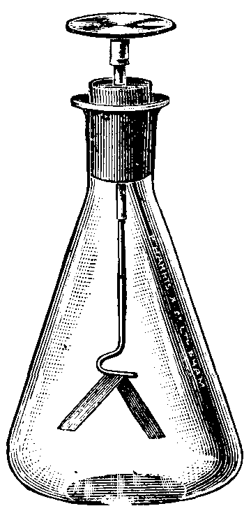
The electroscope is a simple piece of apparatus for detecting the presence of an electric charge, determining its sign (positive or negative), and making a very rough comparative estimate of its potential. It consists of a pair of strips of gold-leaf attached to a brass rod terminating in a brass cap. The whole is enclosed in a glass case, or a case having glass sides. The base is made of conducting material. The sides of the case are coated internally with tinfoil (or two rods connected to the base project upwards to the level of the gold-leaf strips). The general appearance of one form of electroscope is shown in fig. 7. The gold-leaf strips, the brass rod, and the cap must be carefully insulated. When a charged body is brought near the electroscope the leaves become charged similarly by induction. The repulsion due to the similar charges causes the leaves to diverge.
If the cap be touched with the finger, the charge on the leaves is neutralized, and the leaves collapse. On removing the charged body the leaves diverge again, owing to the spreading of the charge on the cap, which was held by the inducing charge, over the whole conductor, including the leaves. The electroscope is thus charged by induction. It may also be charged by conduction, i.e. by the direct transfer of a charge to the electroscope. When we know the kind of charge, positive or negative, which has been given to the electroscope, an unknown charge can be tested. If the approach of the unknown charge causes a further divergence of the leaves, then it is of the same kind as that with which the electroscope is charged.
Fig. 7.—Electroscope
When accurate quantitative measurements have to be made, an instrument called an electrometer is used. This instrument, the development of which is due chiefly to Lord Kelvin, is capable of making accurate measurements of electrostatic potential differences down to quite low values.
Essentially an electrometer consists of a light suspended conductor which moves within four fixed quadrants. Opposite pairs of these quadrants are connected together, one pair to one terminal, and the other pair to the other terminal of the instrument. The P.D. to be measured is applied at these terminals. The suspended conductor or 'needle' is charged to a definite high potential, and the deflection produced is observed from the movement of a spot of light reflected from a mirror attached to the suspending fibre. In this case the deflection is proportional to the P.D. between the quadrants. For measuring a high P.D., the needle may be connected to one pair of quadrants. With such an arrangement the instrument is less sensitive, and the deflection is proportional to the square of the P.D. between the quadrants.
Current Electricity. The phenomena connected with the flow of electricity through a conductor come under this heading. Such a flow of electricity will take place if by some means the ends of the conductor are maintained at different potentials. An electric current is then said to exist in the conductor. The difference of potential may be maintained by chemical action (see Daniell's Cell; Electric Battery), by electro-dynamic action (see Generator), or by heat action (see Thermo-electricity). The magnitude of the current which will flow when a steady P.D. is maintained between the ends of the conductor is determined by what is called the electrical resistance of the conductor. The resistance R is defined as the ratio of the applied potential difference V to the current I produced, i.e. R = V/I. This is a partial expression of Ohm's Law for the Electric Circuit, which in its most general form states that the current which flows at any instant in an electric circuit is equal to the algebraic sum of the electromotive forces existing in the circuit at that instant, divided by the total resistance in the circuit at that instant (see Electromotive Force).
For the particular case where the algebraic sum E of the electromotive forces is steady, and the total resistance R is not varying, we have I = E/R. This is the form which applies to steady direct currents. If the current is changing (whether alternating or merely varying in value), varying E.M.F.'s, in addition to the applied E.M.F., exist in the circuit, and the above expression no longer holds good.
The resistance of a conductor depends on its material, and varies directly as the length, and inversely as the cross-section of the conductor. Thus R = ρ(l/A), where ρ is the specific resistance of the material, l the length of the conductor, and A the cross-sectional area of the conductor. The specific resistance is the resistance between opposite faces of a unit cube of the material at a definite temperature (usually 0° C.). The resistance of a conductor varies to a greater or less extent with variation of temperature.
For pure metals the resistance increases considerably with increase of temperature. With certain alloys the change is so slight as to be negligible. In some alloys, and in carbon and insulating materials, the resistance falls with increase of temperature.
Measurement of Resistance.—Low resistances can most conveniently be measured by a fall of potential method, based on the relationship R = V/I. The current may be read by an ammeter, and the potential difference by a low-reading voltmeter (see Electrical Measuring Instruments). Where greater accuracy is required, a constant current is sent through the resistance to be measured, and also through a known standard resistance of about the same value. A sensitive galvanometer (see Galvanometer) is used to compare the P.D. across the unknown resistance with that across the standard. Since the current is the same through both, the resistances will be proportional to the galvanometer deflections, and from the known value of the standard resistance the value of the unknown resistance can be calculated. Resistances of moderate value are best measured by a Wheatstone Bridge, or one of its modifications (see Wheatstone Bridge).
A substitution method is more suitable for high resistances. A galvanometer is connected in series with a standard high resistance and a steady source of E.M.F. The deflection is noted. The unknown resistance is now substituted for the standard, and the new deflection noted. Provided the resistance of the galvanometer and other parts of the circuit is negligible in comparison with the resistance to be measured, the resistances are inversely as the deflections. The unknown resistance is, therefore, equal to the ratio of the first to the second deflection multiplied by the value of the standard resistance. For insulation tests on installations, direct-reading instruments are frequently used (see Ohmmeter).
Effects of an Electric Current.—When a current flows in a conductor, the temperature of the conductor is raised. This is due to the power dissipated on account of the resistance of the conductor. The power dissipated is equal to I2R watts, and by giving suitable values to I and R any required amount of heat per second can be obtained. This heating effect of the current is made use of in electric lighting, electric heating and cooking, in electric furnaces, and in certain electro-medical appliances.
If a magnetic needle is brought near a conductor carrying a current, it will be found to be deflected. This is due to the magnetic field, which is always associated with an electric current. This electro-magnetic effect is of the utmost practical importance (see Electro-magnetism; Generator; Electric Motors).
When a current is passed through a conducting liquid, such as a solution of a metallic salt or a salt in a fused state, chemical action takes place. The behaviour of such a conductor is entirely different from that of a metallic conductor, since a current can flow in it only if chemical dissociation takes place (see Electrolysis).
Practical use of electrolysis is made in electroplating, the production of electrotype blocks for printing, the refining of copper, and the production of metallic sodium and potassium. Electrolysis is also used as a means of storing electrical energy in a chemical form (see Secondary Cell).
An electric current may be constant in direction (direct current), or may alternate in direction with a certain frequency (alternating current). Alternating currents have advantages for the transmission of large amounts of power over considerable distances (see Electric Power Transmission and Distribution), and may be used for electric lighting and the operation of electro-dynamic machines and apparatus (see Electric Motors).
Bibliography: B. Kolbe, Introduction to Electricity; S. P. Thompson, Elementary Lessons in Electricity; Starling, Electricity and Magnetism; Poynting and Thomson, Electricity; W. E. Ayrton, Practical Electricity; C. R. Gibson, Electricity of To-day; Clerk-Maxwell, Electricity and Magnetism; E. E. Brooks and A. W. Poyser, Magnetism and Electricity.
Electric Light, a light obtained by the conversion of electric energy into light energy. The usual method is to heat some material to incandescence by passing an electric current through it. The material may be carbon (arc lamps), tungsten wire (all modern incandescent lamps), mercury vapour (mercury vapour lamps), or volatilized metallic salts (flame arc lamps). Other materials have been used, such as zirconium, yttrium, and thorium oxides, and osmium and tantalum among the metals, but they have been displaced entirely by the materials mentioned above.
Ordinary arc lamps, and even flame arc lamps, are being displaced by the modern high-candle-power gas-filled tungsten lamp. Flame arc lamps have a high efficiency, and are still largely used for street lighting, but the cost of the frequent trimming required, even in lamps of the magazine type, gives the gas-filled lamp an advantage over them. Lamps of the mercury vapour class have a high efficiency, and the light has a high actinic value which is valuable for certain photographic processes, but the absence of the red and orange part of the spectrum gives the light a characteristically ghastly effect which limits the use of this type of lamp.
The Carbon Arc.—Although the arc lamp has fallen into disuse, the carbon arc is still extensively employed for projection work, as in cinema projectors and in searchlights. The action of the carbon arc is as follows: If a potential difference of about 50 volts is maintained between a pair of carbon rods, and the tips of the rods are momentarily brought into contact and then separated by a short distance, then the current is maintained by an arc across the gap. The temperature of the positive tip rises to about 4000° C., and the tip itself soon becomes hollowed, forming what is called the positive crater.
Fig. 1.—Positive and Negative Carbons
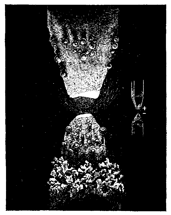
The illustration below represents the two carbons of the arc light as they appear when cold, the positive carbon being marked + and the negative -. The central figure is a magnified representation such as can be obtained by throwing an image of the burning carbons on a screen by means of a lens. In fig. 1 the upper rod is the positive one, and the hollowed shape of the tip is clearly shown. The negative tip becomes roughly pointed in shape, and its temperature is about half that of the positive crater.
The positive crater has an extremely high intrinsic brilliancy, and nearly the whole of the light is emitted from its surface, the negative tip and the arc itself contributing very little. In order to stabilize the arc, a series resistance of a few ohms is necessary. The carbons gradually burn away, the rate of consumption of the positive carbon being about twice that of the negative. It is, therefore, necessary to 'feed' the carbons towards one another. This may be done automatically by the action of a pair of solenoids, one carrying the current which passes through the arc, the other carrying a current proportional to the potential difference across the arc. These solenoids, by means of a suitable mechanism, act in opposition, the current solenoid separating the carbons, and the potential difference solenoid bringing them closer together. The actions balance one another when the arc is of the correct length.
Such an arrangement also serves to strike the arc when the supply is switched on. In order to prevent the arc from wandering round the carbons, the positive carbon is cored, and sometimes the negative carbon also. The core consists of purer softer carbon of lower resistance, and the arc remains centrally placed.
Flame Arc Lamps.—The carbon arc principle is modified in these lamps, so that the arc itself supplies nearly the whole of the light. The arc is made highly luminous by impregnating the carbons with metallic salts, which are volatilized and become incandescent in the arc. Their presence also lowers the resistance of the arc, so that its length can be greatly increased.
The tendency of the arc to wander is also increased, so that cored carbons are essential, and their diameter must be made as small as possible. These thin carbons burn away quickly, so that they must be made proportionately longer for the same time of burning. In order to reduce their resistance a soft-metal inner core is used. The carbons, instead of being placed one above the other, are inclined at a small angle with the arc between their lower ends. The arc is made as large as possible by the action of a small electromagnet placed just above the gap.
The feeding mechanism is similar in principle to that used for ordinary carbon arcs. For street lighting, lamps of the magazine type are used. In these lamps a number of pairs of carbons is placed in the magazine, and as each carbon is used up, a new one automatically takes its place.
Mercury Vapour Lamps.—In these lamps the light is obtained from incandescent mercury vapour in a tube from which the air has been exhausted. The positive terminal is connected to a small iron electrode at one end of the tube. At the other end there is a small bulb, which contains a little pool of mercury, which is connected to the negative terminal. To start the lamp, the tube has to be tilted, so that a stream of mercury flows along it and makes contact with the iron electrode. The current which then flows vaporizes some of the mercury, and when the tube is tilted back to its original position, the discharge is maintained through the mercury vapour. A small series resistance is required in order to make the operation of the lamp stable. For small lamps a glass tube is used, but owing to the higher temperature reached in lamps consuming considerable power, it is necessary to use a quartz tube for large lamps. Quartz is transparent to ultra-violet light, and to avoid harmful effects the tube is usually enclosed in a larger one of flint glass, which stops the ultra-violet rays.
Incandescent Lamps.—This is the name commonly given to the type of lamp in which the light is produced by an incandescent filament. The filament is enclosed in a glass bulb, which is either exhausted to a high vacuum, or else contains an inert gas under pressure. The filament is heated to incandescence by the current passing through it.
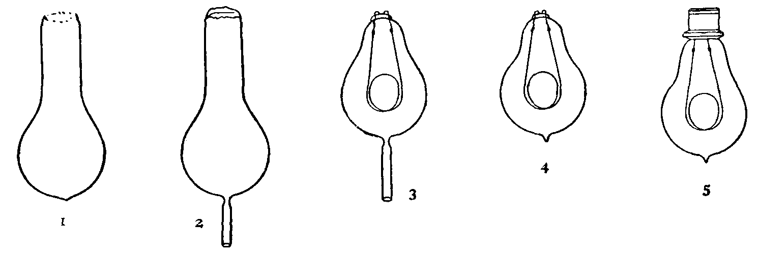
Stages in the Manufacture of an Incandescent Lamp
1, Bulb as received from furnace. 2, Stem attached for exhausting. 3, Filament sealed in. 4, Lamp exhausted of air. 5, Finished lamp.
The first lamp of this type to come into general use was the carbon filament lamp. This has now been ousted by the much more efficient tungsten filament lamp. The earlier tungsten lamps were very fragile, owing to the brittleness of the filament. Later, a process was discovered whereby tungsten could be made malleable. The manufacture of drawn-wire filaments thus became possible, and the tungsten filament lamps which are now produced will stand a considerable amount of rough handling. This type of lamp is now in universal use for house lighting.
The limit of temperature at which the filament can be worked is set by the disintegration of the filament, which blackens the bulb and weakens the filament till it breaks. Recent research has revealed that this is due to a double chemical action between traces of water vapour and the incandescent metal. No method of entirely removing water vapour from the bulb has been found, but further research has brought to light the important fact that if the bulb is filled with an inert gas under pressure, the action is reduced to a minimum. This allows the filament to be worked at a much higher temperature, and since the light emitted increases with temperature much more rapidly than the power consumption does, the efficiency of the lamp can be greatly increased. These discoveries have led to the development of the modern gas-filled lamp. Owing to the high intrinsic brilliancy of the filament, high candle-power lamps of this type can be made which are not unduly bulky. For this reason, and because of their high efficiency and the absence of the need for any adjustment or attention, gas-filled lamps are coming into extensive use for street lighting and for factory and workshop lighting. Smaller lamps of this type are also being widely adopted for the illumination of shop windows.
Electric Motors, the name given to that division of dynamo-electric machinery in which electrical power is converted into mechanical power.
Electric motors are classified as direct-current motors or alternating-current motors, according as the electric power taken by the motor is in the form of a direct current or an alternating current. Further subdivisions of each class are made on the basis of differences in the operating characteristics of the various types.
Direct-current Motors.—The motor consists of a fixed magnetic field system with a rotating armature, which carries the conductors through which the supply current is passed. The magnetic field, produced in the air-gap between the poles and the armature, reacts with the current-carrying conductors of the armature and produces the mechanical turning-moment or torque.
At the same time the motion of the conductors through the magnetic field generates an E.M.F. in the conductors. This E.M.F. is in the opposite direction to the applied E.M.F., and is, therefore, called the back E.M.F. of the motor. The current taken by the motor is equal to the difference between the applied and back E.M.F.'s divided by the resistance of the armature winding. Since the armature resistance is always low, and the back E.M.F. is zero at starting, some form of starter is necessary in order to limit the current to a safe value. Essentially the starter consists of a suitable resistance connected in series with the armature. As the motor gains speed this resistance is gradually reduced to zero.
The speed at which a D.C. motor runs varies inversely as the air-gap flux per pole, and very approximately, directly as the applied E.M.F. (directly as the back E.M.F. actually).
The torque produced is proportional to the product of the air-gap flux per pole and the armature current. The torque and speed characteristics of a D.C. motor, therefore, depend on the manner in which the air-gap flux per pole varies with the load current.
Series Motor.—In this type the field magnet windings are connected in series with the armature winding, i.e. the same current flows in both windings. The air-gap flux per pole, therefore, depends on the current taken by the motor. Consequently, at light loads the speed of the motor is very high, and there is a very large fall in speed as the load increases. The torque increases rapidly with load for the same reason. At starting, a large torque is obtained at a low speed. These characteristics are specially suitable for traction purposes, for crane motors, and for the motors for certain machine tools.
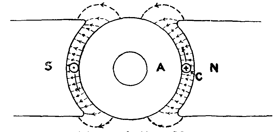
Diagram of a Simple Motor
C, Conductor on surface of iron core A, which is free to rotate between the poles N S of an electro-magnet.
Shunt Motor.—In this case the field magnet windings are connected as a shunt to the armature windings, i.e. the current in the field coils depends upon the applied voltage, and is, therefore, constant in normal operation. Apart from the slight effect of the armature magneto-motive force, the air-gap flux per pole, therefore, remains almost constant at all loads. This means that the speed is practically constant at all loads (a very slight fall in speed with load occurs), and the torque, therefore, is almost directly proportional to the load current. The shunt motor is, therefore, suitable for all cases where an approximately constant speed at all loads is required.
Alternating-current Motors.—There are wide differences between the various types, both in construction and operation. The type most commonly used is the polyphase induction motor. In this motor both the field system and the armature consist of a slotted core built up of iron laminations. The field system is called the stator, and the armature the rotor. Both carry conductors in their slots, and these conductors in each case form a polyphase winding. Current is supplied to the stator winding only. The currents in the rotor winding are induced by the action of the rotating magnetic field set up by the stator currents. Hence the name induction motor. For starting, a polyphase resistance completes the circuits of the rotor winding. This resistance is gradually reduced to zero as the motor attains its full speed.
The rotor circuits are, therefore, closed upon themselves in normal operation. In many motors (especially small ones which are started unloaded) the rotor winding consists of a series of copper bars brazed to solid end-rings at each end of the core, thus forming a permanently short-circuited winding. Such a rotor is known as a squirrel-cage rotor.
The speed characteristic of the induction motor closely resembles that of the shunt D.C. motor, and induction motors are suitable for similar purposes. The induction motor gives its maximum torque at a speed only slightly below the synchronous speed (corresponding to the number of poles in the stator winding and the frequency of the supply); and the torque decreases very rapidly as the speed rises towards synchronism. The maximum torque has a definite value for a given motor, and if the load demands a greater torque than this, the motor slows down and stops.
Synchronous motors are seldom used except for special purposes. They are exactly similar to the ordinary synchronous generator or alternator in construction, and the field system is almost invariably the rotating part. As their name implies, these motors have the characteristic of running at synchronous speed at all loads. If through overloading, or for any other reason, the motor is unable to maintain its synchronous speed, it immediately falls out of step and stops.
Alternating-current Commutator Motors.—These motors are in general appearance similar to the induction motor, but the rotor is fitted with a commutator. According to the electrical connections, these motors may be given characteristics similar to direct-current series or shunt motors. Single-phase commutator motors with series characteristics are used on the L.B. & S.C.R. electric trains.
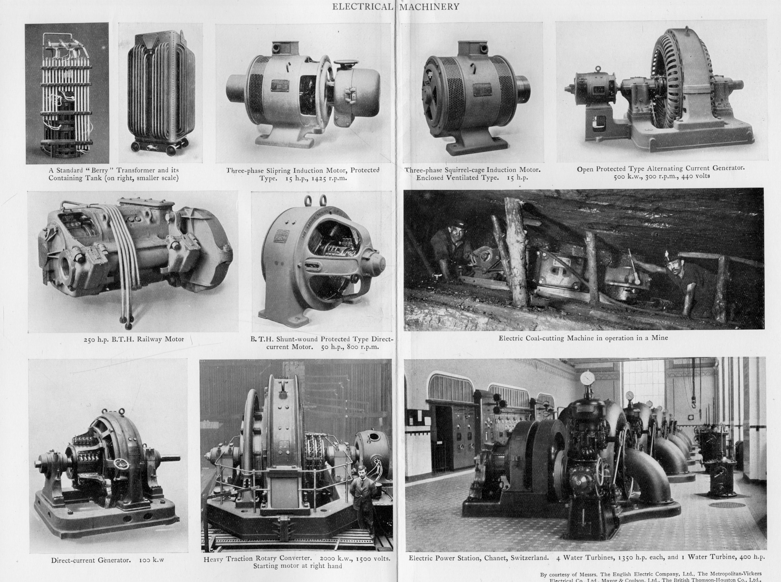
Electric Power Transmission and Distribution. In the public supply of electric power in this country, the usual practice is to use alternating-current generators in the power stations, and to transmit the power at a high voltage to substations. The substation plant reduces the pressure to a value suitable to the consumer, and in many instances also converts the alternating current into direct current. From the substations the power is distributed to the consumers.
For a given amount of power transmitted the cross-section of the cables required varies inversely as the square of the voltage. In order to reduce the outlay on cables, it is important that the transmission voltage should be as high as the circumstances permit. Naturally this becomes more and more important as the distance over which the power has to be transmitted increases. In America, where large amounts of power are transmitted over very great distances, the pressure used is in some cases 150,000 volts, and the tendency is to raise this till further, as switch gear, insulators, and other apparatus capable of withstanding this high pressure are becoming available. For high-tension underground cables, the pressure now coming into common use is 20,000 volts.
The nature of the low-voltage distribution from the substations, whether alternating current or direct current, depends largely on the requirements of the consumers.
There are certain advantages in the use of direct current, and in this country it is more commonly employed than alternating current, but the substation plant is more costly and requires skilled attendance. If the circumstances are such that these advantages are not important, the lower initial cost and running expenses of an alternating-current distribution would lead to its adoption.
In the Thury system of power transmission high-voltage direct current is used throughout. Only one supply in this country is of this kind, but several are in operation on the Continent. Pressures up to 100,000 volts are used.
Electric Telegraph. See Telegraph.
Electric Traction and Electric Tramway. In electric traction the mechanical power required for the propulsion of the vehicle is obtained from electric motors. These motors are usually series direct-current motors, but for railway work single-phase and three-phase A.C. motors have also been successfully employed (see Electric Motors). Up to the present, electric traction on railways has only been employed for suburban traffic in this country. In one instance (L.B. & S.C.R. electrification) single-phase alternating current is used. In all the others the power supply is direct current (see Railways, Electrification of).
In electric tramways, except in some few instances where there are objections to the use of an overhead construction, the current is conveyed to the motors through a trolley pole carrying a wheel running on an overhead bare copper wire. A hand-operated drum controller, directly controlling the driving and electric braking of the motors, is used. A hand-brake, and commonly a separate electro-magnetic brake, are provided.
Except in very small tramway systems, the power is generated as high-tension alternating current, and transformed and converted at substations suitably placed in the area covered by the tramway (see Electric Power Transmission and Distribution). The low-tension D.C. power is distributed from the substations to the trolley wire. The car rails are earthed, and provide a return path for the current. In order to minimize the flow of current to other conductors in the vicinity of the car rails, copper cables returning directly to the substation are connected to the rails at suitable intervals. These earth-return cables are connected in series with special low-voltage dynamos (called negative boosters) at the substation. This arrangement automatically keeps the P.D. between the most distant point of the car rails and the substation within a prescribed maximum, and effectively prevents the corrosion of pipes laid near the car rails.
Elec´trode (Gr. hodos, a way), a term introduced by Faraday to denote the wires or other terminals by which electricity either enters or leaves a body which is undergoing electrolytic decomposition. He called the electrode at which the current enters the anode (ana, upwards), and the electrode at which the current leaves the electrolyte the cathode (kata, downwards). (See Electrolysis; Electro-metallurgy.) The word is now commonly used in a wider sense to denote the conductor by which contact is made with a medium. In this way electrodes are spoken of in connection with electric furnaces, electric welding appliances, vacuum tubes, and mercury vapour lamps, although the actions are not electrolytic.
Electrol´ysis (Gr. lysis, loosening) is the name give to the decomposition of fused salts or solutions of salts, &c., by means of the electric current, and is thus a branch of electro-chemistry. The substance through which the current is passed is termed the electrolyte, and must be either an acid, base, or salt in a fused state or in solution. The current enters the electrolyte by an electrode called the anode, or the positive terminal. The electrode by means of which the the current leaves the electrolyte is termed the cathode, or negative terminal.
During the passage of the current the electrolyte is decomposed, and the products of decomposition are released at the electrodes or terminals. According to the modern theory of electrolysis, all electrolytes contain a greater or smaller number of free ions. These ions are chemical radicles carrying a definite electric charge. The kind of charge, positive or negative, depends on the nature of the radicle. The ions exhibit none of the chemical properties of the uncharged radicle.
Thus, for example, in an aqueous solution of sulphuric acid, free ions of hydrogen H2 carrying a positive charge, and free ions of SO4 carrying a negative charge, exist. An uncharged SO4 radicle would react with the water present, and sulphuric acid would be formed and oxygen liberated. The ion SO4, however, is incapable of doing this. Owing to the nature of their charges, the hydrogen ions will move towards the negative electrode, and the SO4 ions towards the positive electrode. On reaching the electrodes the ions give up their charges, and immediately exhibit their ordinary chemical properties. Hydrogen is given off at the negative electrode, while at the positive electrode the uncharged SO4 radicle reacts with the water present, and oxygen is released.
This is an example of a secondary chemical reaction. This occurs in many cases, and where it occurs the final product is different from that first produced by the electrolytic action. Fresh ions are formed or dissociated in the electrolyte as fast as the original ions give up their charges at the electrodes. If this were not so, the electrolytic action would soon cease, since there would be no ions left to move towards the electrodes. The stream of ions carrying their positive and negative charges constitutes the current flowing through the electrolyte. Since the ions carry definite charges, it follows that the amounts of the initial products of an electrolytic action are in the ratio of their chemical equivalents. Thus, if fused silver chloride be electrolysed, for every 108 grammes of silver deposited at one side of the vessel 35.5 grammes of chlorine are given off at the other side (see Electrode; Electro-metallurgy).
The electrolytic action of the current is the same at all parts of the circuit. If the current is made to traverse several vessels, each containing the same substance, all in series (that is, the current that leaves the first entering the second, and so on), it will be found that in each of the cells precisely the same amount of decomposition goes on. There will be the same weight of silver deposited at one side, and a corresponding weight of chlorine set free at the other.
The same quantity of electricity decomposes chemically equivalent quantities of different electrolytes. If we pass the current through a series of cells containing different electrolytes, for example, dilute sulphuric acid, chloride of silver, sulphate of copper, and collect the products of decomposition, we find that the quantities of hydrogen, silver, and copper set free are strictly proportional to the chemical equivalents of these bodies.
The quantity of the electrolyte decomposed in a given time is proportional to the strength of the current. This fact is made use of in measuring electric currents for standardization purposes, and the practical unit of current (the ampere) is defined, "with sufficient accuracy for all practical purposes", as being "that steady and unvarying current which deposits silver from a specified solution of silver nitrate at the rate of 0.001118 grammes per second".
The practical applications of electrolysis include the refining of copper, the electro-deposition of metals, electroplating, electrotyping, and the production of metallic sodium and potassium (see Electro-metallurgy). Electrolytic action is also made use of in the storage of electric energy in secondary batteries (see Secondary Cell).
Electro-magnetism, that branch of science which deals with the mutual relations between electric and magnetic fields (see Electricity; Magnetism).
It may readily be shown that when an electric current flows in a conductor, a magnetic field is produced around that conductor, i.e. that a magnetic field is produced by the motion of an electric field. Similarly, if a magnetic field is moved at right angles to a conductor, a potential difference is established between the ends of the conductor, i.e. an electric field is produced by the motion of a magnetic field.
Fig. 1
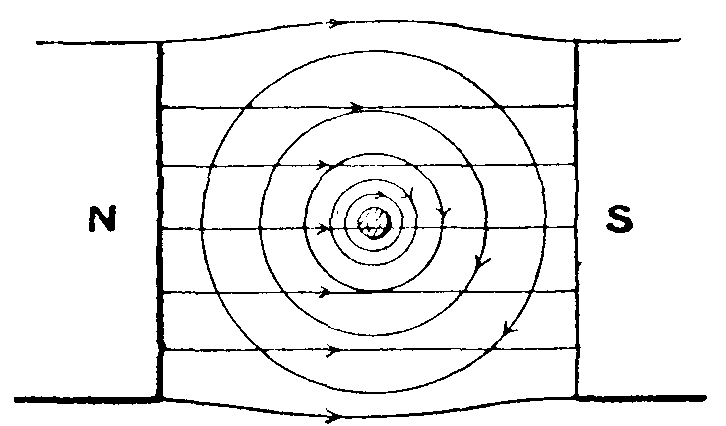
If a conductor is placed in a magnetic field so that its length is at right angles to the lines of magnetic force (see fig. 1), and a current is passed through the conductor, a mechanical force will act on the conductor, and this force will be at right angles both to the conductor and to the original magnetic field.
Fig. 2
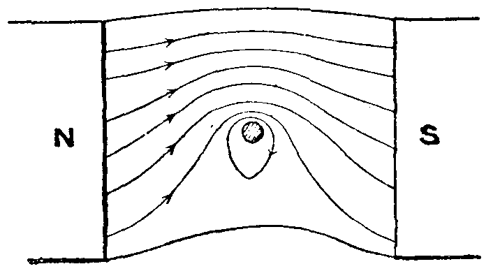
From the point of view of lines of magnetic force, the magnetic field produced by the current in the conductor (shown by the concentric circles in fig. 1) will react with the original magnetic field (shown by the horizontal straight lines in fig. 1), and the actual resultant magnetic field will have the form shown in fig. 2. The tendency of lines of force to shorten themselves and repel one another laterally results in a force tending to force the conductor vertically downwards. This force is, of course, mutual, and tends to move the original magnetic field in the opposite direction.
All the phenomena of electro-magnetic action have their basis in these three effects, viz. (1) the production of a magnetic field by an electric current; (2) the production of an E.M.F. or P.D. by the relative motion of a magnetic field and a conductor; and (3) the mutual mechanical action between a current-carrying conductor and a magnetic field system.
The strength of the magnetic field produced by the current may be increased by winding the conductor in the form of a helix or solenoid consisting of a number of turns. The effect can be very greatly increased by providing the solenoid with a soft-iron core. The iron is strongly magnetized as long as the current flows. Such an arrangement is called an electromagnet. Electromagnets specially designed to produce a very intense magnetic field are used commercially in handling scrap-iron, pig-iron, &c. The electromagnet takes the place of the crane-hook in an ordinary crane. When the current is switched on, the pieces of iron are attracted and held firmly until the current is switched off again.
Electromagnets are also used for extracting fragments of iron or steel from the eye, and for many laboratory purposes. The most important practical use is the production of the magnetic field required in dynamo-electric machinery (see Generator; Electric Motors). The magnetic field produced within a coil in which a current flows is made use of to give the deflecting couple in certain types of galvanometers and measuring instruments (see Galvanometer; Electrical Measuring Instruments).
The absolute C.G.S. unit of current is defined in terms of the magnetic field strength produced by it, viz. "when one absolute C.G.S. unit of current flows in a circular loop of one centimetre radius, the magnetic force produced at the centre of the loop is 2π dynes".
The principle of the electromagnetic generation of an E.M.F. is dealt with under the article Electro-motive Force. The mechanical force produced when a current flows in a conductor placed in a magnetic field forms the basis of the action of electric motors, and certain types of galvanometers and measuring instruments. The mechanical force is a mutual one, and tends to move the conductor and the field system in opposite directions. The magnitude of the force varies as the magnetic field strength, the length of the conductor, and the intensity of the current, and also as the sine of the angle between the field and the conductor. Thus when the direction of the lines of magnetic force is parallel to the conductor, the force is zero; and when their direction is at right angles to the conductor, the force is a maximum. The direction of the force is always at right angles both to the conductor and the direction of the lines of magnetic force. In an electric motor the forces acting on the conductors produce the mechanical output of the machine. In a generator these mechanical forces come into existence as soon as current is taken from the machine. In this case they produce a torque which is opposite in direction to the mechanical torque which is applied to the shaft of the generator in order to drive it.
Electro-medical Apparatus. Electrical apparatus is now widely used in the treatment and diagnosis of disease. The action of the heart may be very accurately observed by means of the electric cardiograph. The cardiograph itself consists of a very sensitive 'string' galvanometer (see Galvanometer) and an arrangement whereby the spot of light is focused on a moving photographic plate. In this way a photographic record of the movements of the galvanometer mirror is obtained. The galvanometer terminals are connected to two different parts of the body of the patient (say to a hand and a foot placed in separate brine baths), and the variations of potential differences which occur during a heart-beat cause a movement of the galvanometer mirror.
The X-ray apparatus has recently been adapted for taking instantaneous photographs of the heart. A single powerful discharge from a static transformer takes place through the tube, and a photograph of the position of the heart at that instant is obtained. The X-ray apparatus is very well known from its use in locating fractures, foreign bodies, diseases of the bone, &c.
The X-ray discharge is used as a treatment for certain skin diseases (especially ring-worm), rodent ulcer, and cancer. Very high-frequency alternating currents may be passed through the body without producing the muscular contractions which are a feature of the passage of low-frequency currents through the tissues. Currents of considerable magnitude of very high frequency may thus be passed through the body without inconvenience to the patient. In this way general or local heating of the body may be obtained. This process is known as diathermy. The heating locally may be made sufficiently great to cause coagulation of the tissues, or even actual burning. This method is used in the treatment of tumours and other growths.
Another important electro-medical treatment consists of the local introduction of a drug, into the affected part, by electrolytic action. Thus in the treatment of rodent ulcer, a pad of lint saturated with a 5 per cent solution of zinc sulphate is placed over the ulcer. A zinc electrode is placed on the pad and connected to the positive pole of the supply. The negative pole is connected to a basin of brine in which the patient's hand is placed. The current is made as large as can conveniently be borne (say 30 to 60 milliamperes), and is maintained for about thirty minutes and then gradually reduced to zero. By this means zinc ions are carried into the ulcer. A number of diseases may be treated in this way, the ion used depending on the nature of the case.
Low-frequency intermittent currents from induction coils are frequently used where nerve stimulation or muscular contractions are required. Static electricity is also used for similar purposes. Large Wimshurst machines are used for the treatment of sciatica, and also for neurasthenia. In the latter case a brush discharge is used, and the patient experiences very little physical sensation. The high-frequency apparatus already referred to in connection with diathermy is valuable for the treatment of rheumatism in its earlier stages, and for the stimulation of the scalp in hair treatment. Suitable electrodes are passed backwards and forwards over the affected parts, a bluish brush discharge taking place between the patient and the electrode.
Electro-metallurgy is that branch of metallurgy which uses electrical energy, wholly or in part, for the extraction or treatment of metals. The energy may be converted into heat and used for processes in which high temperatures are necessary, or it may be used for the decomposition of a compound by electrolysis, which may proceed in a fused bath at a comparatively high temperature, or in a solution bath containing a compound of the metal dissolved in a suitable solvent.
The former method of utilizing the energy embraces electrothermal processes, and the latter method, electrolytic processes.
In electrothermal processes, the heat developed by the electric current has been used in a number of industries, including welding, annealing, heat treatment, smelting, refining, &c. Laboratory apparatus, such as tubes, muffles, and crucibles, are also frequently heated by means of an electric current.
For the electric welding of metals there are two systems in use: resistance welding, in which the portions to be welded are pressed together and heated by the resistance they offer to the passage of a current; and arc welding, in which portions of metal of the same composition as that to be welded are fused on by striking an arc from a suitable electrode. In the electrical annealing of metals, case-hardened steel plates are locally softened where rivet-holes, &c., are required by passing an electric current through copper poles placed 1 or 2 inches apart on the smooth surface. Metallic wire is frequently heated to the annealing temperature between drawing operations, and various types of annealing furnaces are also electrically heated.
In electric smelting, the high temperature of the arc (3600° C.) may be used for the reduction of certain metallic oxides, which at the lower temperature of furnaces heated by coal, coke, gas, &c. (2000° C.), will not give up their oxygen to carbon; other ores are also sometimes smelted by electrical means, especially in localities where current is cheap and fuels are dear. The production of refined steel, special alloy steels, and certain non-ferrous alloys is also carried out in electric furnaces of various types.
The electric arc was first applied to fusion by Siemens in 1879; he fitted, into the bottom of a crucible to receive the charge, a water-cooled copper casing to form the positive pole, and suspended a carbon rod centrally in the crucible to form the negative pole. The current crosses the air-gap between the metal and the negative pole, forms an arc, and rapidly fuses the metal. In 1885 the Cowles Brothers, of Cleveland, Ohio, began to produce aluminium-copper and aluminium-iron alloys by arc smelting, and later produced other metals, difficult to reduce, by the same means. More recently, the development of electric smelting has made rapid strides. Electric furnaces not only yield higher temperature, but have other advantages over furnaces heated by carbon. They develop the heat in a small space, just where it is required for the operation, so that the furnace can be smaller, and less heat is lost by radiation; the charge can be kept free from gaseous products of combustion; the temperature and the whole operation is under better control; and the expense of running the furnace is limited to the time the current is used for doing useful work.
Electric furnaces are now used in the production of pig-iron, steel, ferro-alloys, brass, zinc, &c., and in the heat treatment of various metals. Classifying them according to the manner in which the electrical energy is converted into heat, we have:—
1. Direct resistance furnaces, in which the heat effect is produced within the metal itself by the resistance offered to the passage of the current through it. This type is used in the refining of steel.
2. Indirect resistance furnaces, to which class belong the various tube and crucible furnaces used in laboratories. The vessels to be heated are wound with wire or ribbon of high resistance, such as platinum, nickel-chrome alloys, &c., and a suitable current passed. Heat-treatment furnaces on a fairly large scale also use this method, a nickel-chrome alloy ribbon being wound on a suitable framework; the heating element in these furnaces, however, generally consists of granular carbon confined in carborundum fire-sand troughs.
3. Induction furnaces, in which a primary coil of copper wire is used, the secondary being formed by the metal charge itself, contained in a suitable annular groove. In this furnace the current passes through the primary and induces a current in the charge, thus melting it. This type of furnace has been largely used in the refining of steel, and to some extent in the melting of non-ferrous metals and alloys.
4. Direct arc-heating furnaces, as exemplified in the Siemens crucible furnace mentioned above.
5. Indirect arc-heating is used in the Stassano furnace, in which the heat is obtained by radiation from the arc, and by reflection from the roof and sides of the furnace. This furnace has been used in the production of steel from scrap, and also direct from ore. There are three electrodes, which nearly meet in the centre of the furnace.
6. Combined resistance and arc furnaces are very largely used for the production of ferrous alloys, such as ferro-silicon, ferro-chrome, and ferro-manganese; for the production of steel from scrap, and for the final refining of steel produced by other processes. In these furnaces the heat is generated largely by the arc, and to a smaller extent by the resistance offered by the whole or a portion of the furnace charge to a powerful electric current. There are several well-known commercial furnaces working on this principle, the best known probably being the Héroult. This furnace is designed for tilting, and is lined with basic material, and large electrodes pass through the roof. An alternating current of 4000 amperes at 110 volts is used for a 3-ton furnace, and the intensity of the current passing through the bath is regulated by raising or lowering the electrodes.