Preparing and Stamping of Jacquard Cards.
Reading edition
Preparing.
The Jacquard card consists of a strong, durable pasteboard cut to the exact size of the cylinder. For cutting or preparing the cards to the required size, a table is used with the different sizes of cards indicated on its surface. A sharp steel blade is adjusted to the side of the table. A heavy knife of sufficient length, and containing a second steel blade, is secured to a projecting bolt on the rear end of the table, allowing enough play for the knife to be easily raised and lowered. The blade of the knife works close against the blade fastened to the table; and when pressed down both blades rest close together. On the front side of the table is a long groove in which is a guide, fastened by a bolt and nut. This guide can be set to suit any of the marks on the table, thus regulating the size of the cards to be cut.
Two measures (the length and the width) are required to be cut for each set of cards: 1st. The sheets of pasteboard are required to be trimmed one way in sufficient number for the length of the cards. 2d. Each trimmed sheet is afterwards separated in strips of the required width.
Card Stamping.
The oldest method for stamping cards, now only occasionally used, consists of two perforated steel plates, between which the blank cards are placed, and the required holes stamped by hand by means of punches. It will easily be seen that this method is not up to the present advanced times, hence various machines have been introduced for arranging the punches. Among those most generally used are:
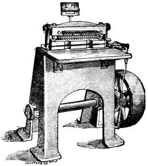
Fig. 1.
I.— Dobby Card Punching Machines.
II.— Piano Card Stamping Machines.
III.— Repeating Machines.
I. Dobby Card Punching Machines.
These machines, illustrated by Fig. 1., (W. P. Uhlinger, builder), are used for stamping cards for the smaller Jacquard machines, technically termed “Dobbies.” They are of very compact build, and operated by belt-power. The whole card is punched at one revolution or stroke. The rack on top of the machine holds the design. The punches for peg-holes and lace-holes are immovable, while the key punches act independently, at the will of the operator. Jacquard cards for these machines are generally composed of the strongest pasteboard, and require a very strongly constructed machine.
II. Piano Card Stamping Machines.
These are operated in two ways, by the belt or foot-power. There are two kinds of each: “French index” and “American index.”
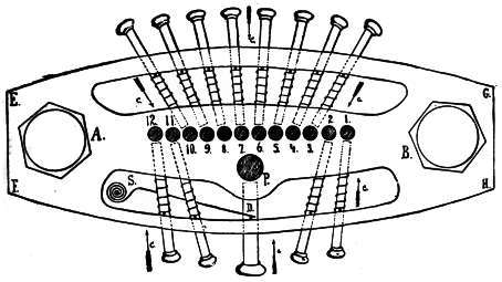
Fig. 2.
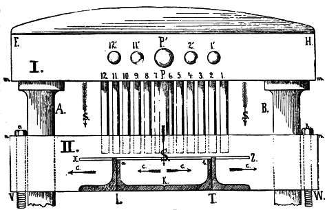
Fig. 3.
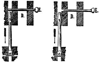
Fig. 4. Fig. 5.
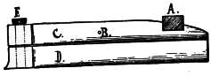
Fig. 6.
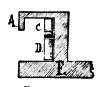
Fig. 7.
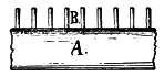
Fig. 8.

Fig. 9.
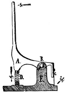
Fig. 10.

Fig. 11.
Figs. 2 to 11 are drawn to one-half the actual size of the “Uhlinger Card Stamping Machine.”
Figs. 13, 16, 17, 18, 19 are drawn to one-quarter the actual size of the “Royle Card Stamping Machine.”
Figs. 2 and 13 (E, F, G, H,) represent the top view of the head (cover taken off), the twelve holes for holding the punches for one row, also the large hole for holding the peg, P. Each punch works vertically, and is guided by a key for stamping the hole.
Fig. 14 illustrates the punch (actual size) as used in the “Royle” machine: a to b = 3/4 inch; b to c = 2-7/8 inches; 7/32 inch diameter of punch, d to c.
Fig. 15 illustrates a corresponding key: diameter of key 3/16 inch, d to e; diameter of head, 3/8 inch, a to b; c is the hole for inserting the pin which holds the spring. The length of the keys vary from 1-3/4 to 2-1/8 inches, according to the position they occupy in the machine. The punch and key of the Uhlinger machine are shown (one-half of actual size) in Figs. 4 and 5.
A and B, in Figs. 2 and 13, represent the piston for guiding the head in its vertical motion.
Fig. 3 represents the front view of the head. The numbers and letters indicating the different parts correspond with Fig. 2.
The principle of construction and action of the heads in both kinds of machine are similar. Each key is provided with a fine spiral spring, which, after every action of the key, returns it to its original position. The key for the peg-hole is controlled by the larger spring, S, D, in Figs. 2 and 13. The arrows in these two drawings indicate the direction taken by the keys when under pressure.
When cutting cards eight rows deep, the thumb of the right hand works the key for the peg-hole; the eight keys in the rear of the machine (which are the ones to be used) are worked by the four fingers of each hand.
When cutting cards twelve rows deep, the eight keys in the rear are operated by the eight fingers in the same manner; but the thumb of the right hand operates keys marked 1 and 2, and the thumb of the left hand operates keys marked 11 and 12.
During the cutting operation the fingers should not be removed from the keys; they should always be in readiness to press the required key into action, as this is the only way to become expert.
The eye of the card stamper must rest uninterruptedly on his design; and the keys are called at will by the fingers, without the eye leaving the design, to find out where a certain key or finger is situated at the time.
Fig. 4 shows relative positions of punch, S, and key, E, when ready for stamping a hole.
Fig. 5 shows the relative positions of punch and key when no hole is required.
O represents the Jacquard card as resting in the slot of the lower head. II. in Fig. 3, marked X to Z, shows a full width view of this card.
The space D, in Figs. 4 and 5 permits the spring to be inserted regulating the key. A, B, C, solid parts of the upper head, (I., in Fig. 3). F, G, K, L, solid parts of the lower head, (II., in Fig. 3).
The cards are passed into and through the stationary part of the head at X, Z, and are attached to a “carriage” in the rear of the punch head.
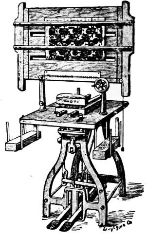
Fig. 12.
Two methods are employed for moving the carriage:
1st. By a “skipper” at its rear fastened to the carriage, which moves in a rack of pins secured to the cutting table. This method of construction is used by the Uhlinger machine. Figs. 6 and 7 are front and side views of this mechanism. Figs. 8 and 9, the top view and sectional cut of the rack.
2d. The rack is fastened to the carriage, and the skipper to the table, thus reversing the first method. [See Fig. 19, top view.] This method of construction is employed in the Royle machine.
The distance of the pins in the racks in both systems of construction (American and French) corresponds to the distance of the rows in the card. The racks are generally constructed for 600, 900, and 1200 Jacquard machines. Of these three sizes the 1200 is the most advantageous, as cards can be cut for any smaller size machine. The rack of a 900 machine (French index) contains 88 pins, while that of a 1200 machine (French index) contains 114 pins.
Fig. 10 illustrates the “catch” for holding the cards in the Uhlinger machine. This is fastened to the carriage when pressed by the hand on top in the direction of arrow, S; this catch will compress spring, D, in the direction of arrow, S´, thus opening the “blade,” C, (front view shown by Fig. 11), in the direction of arrow, S´´, thus allowing the card to be inserted and held, securely fastened to the carriage.
Fig. 18 illustrates the side view of the carriage and its catch for holding the Jacquard card as used in the Royle machine. Arrow, S, indicates the pressure of the operator’s hand on lever, B, when the card is inserted. This lever presses by means of presser, D, in the direction of arrow, S´, on the double-acting lever, E, at c. This lever moving around its fulcrum, e, will lift catch, F, in the direction of arrow, S´´, thus allowing the card to be inserted. Spring, G, fastened to main part of carriage, A, by means of screw, a, secures the card to the catch. C, C´, are the carriage wheels, of which there are four.
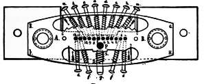
Fig. 13.

Fig. 14.
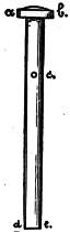
Fig. 15.
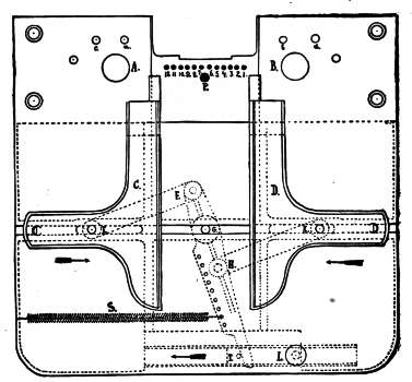
Fig. 16.
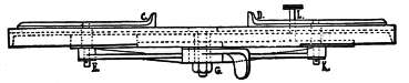
Fig. 17.
Fig. 18.
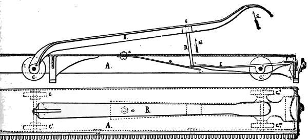
Fig. 19.
Fig. 19 represents the top view of Fig. 18, and is designed to show the arrangement of levers, wheels, and catches of the complete rack as used for a 900 machine. The letters indicating the different parts correspond with the ones used in Fig. 18.
Fig. 16 shows top view and ground plan, and Fig. 17 the front elevation of the “card-guide,” as constructed on the Royle machine. It is universal and self-adjusting to any width of cards from 3/4 to 3-1/2 inches; both guide-plates, C and D, are caused to move equally toward or away from the peg-punch, thus accurately centering the peg-hole in all cards.
Letters A, B, P, and numbers 1 to 12, correspond to those used in Fig. 13. E, F, H, K, are the three levers moving around pin, G, (the latter in even line with the centre of the peg-hole, P). These levers are held by screw, L, in any required position. Spring, S, holds lever, F, H, against pin, T, which in turn is fastened to the same plate as screw, L.
Fig. 16 indicates the card-guide set for a 12-row card. Let us suppose it necessary to cut an 8-row card. Loosen screw, L, and spring, S, will instantly contract until each side of the guide has moved the required distance (two holes and two spaces between holes) towards the centre. Much valuable time is saved by the use of this guide, as it instantly adjusts itself to any width of card, and at the same time centralizes each card passed through the machine. In factories where broken cards require to be constantly renewed, the value of this guide is especially noticeable, there being no material interruption of the regular work of the operator, who can replace the damaged card at the moment wanted.
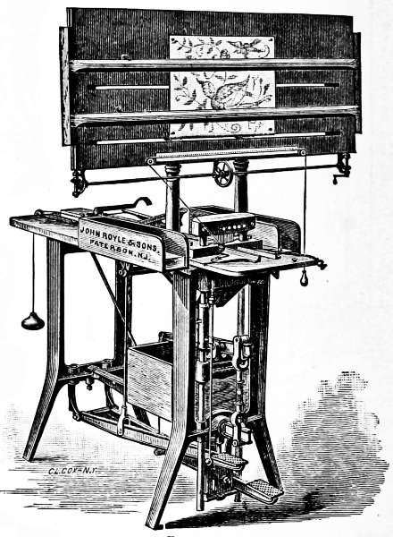
Fig. 20.
Letters indicating the different parts in Fig. 17, correspond to those used in Fig. 16. As mentioned before, the pistons, A and B, of the cutting head are connected below the table to the cutting levers, and by a simple combination of levers, the cutting pedal is brought in direct relation to the cutting lever; all of which are illustrated in the perspective view of the Royle machine in Fig. 20, and the Uhlinger machine in Fig. 12. The working of the cutting pedal is very simple. Pressing the pedal, situated at the right, causes the punch head to descend, and the punch penetrates the card. Transferring the pressure from the right to the left pedal raises the punch-head to its former position, (punches above card), ready for a repetition of these movements. The “skip” arrangement allows the carriage to advance the distance from one pin to the other in the card-rack, thus placing the card in proper position under the punches.
At the proper height above the punch-head is the reading-board, on which the guide-rules are moved across the design by screws, which are connected by gearing and operated by means of the hand-wheel or crank shown on the lower side of the board. As drawing-pins or thumb-tacks are generally used as fastenings for the design, the reading-board is made of soft wood, and its trimmings are made of hard wood.
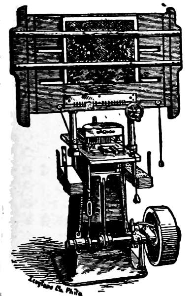
Fig. 21.
Fig. 21 illustrates the Uhlinger Card Stamping Machine operated by belt-power. Being the same in principle as the foot-power machine, it is only necessary to state that instead of working the machine by means of the cutting pedals, it is done automatically by simply touching any of the keys that operate the punches; thus the machine makes one stroke and punches the required holes.
The Stamping of Cards.
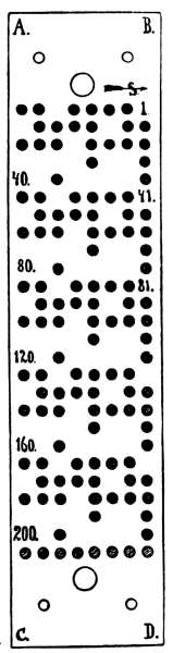
Fig. 22.
Before commencing this work a clear conception of the tie-up and leasing of the heddles is required. The holes in the cards for the needles to penetrate, or the spots in cards where no hole is to be stamped, must be arranged in an uninterrupted chain from one row to the other, until all the rows are taken up. As previously mentioned, the method observed in tying-up the loom is the guide for stamping the cards. The number of ends required in a certain design may repeat only once in the number of hooks and needles employed in the Jacquard machine; or they may repeat two, three, or more times.

Fig. 23.
Fig. 23 illustrates a design upon 40 warp-threads. Fig. 22 shows the corresponding card, (French index), one-fourth of its actual size, for the first pick. In a 200 machine this design will repeat itself five times. The lace-holes and the peg-holes are blank. The reserve row (26th) is shaded, and the design as cut in card is indicated by black dots. This cut also shows the direction of reading each row to correspond with the numbering for the punch-heads, in Figs. 2, 3, 13, and card-guide in Fig. 16. The numbers 1 to 40, 41 to 80, 81 to 120, 121 to 160, 161 to 200, indicate the direction of stamping the design, as well as the five repeats to form the complete card. In this connection it will be of great advantage to examine Fig. XXIX., p. 28, under the head of the Jacquard Machine and its Tie-ups.
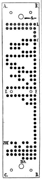
Fig. 24.
Fig. 24 illustrates a Jacquard card (American index) stamped for ingrain carpets, one-half of actual size. This card illustrates the stamping for two textures, 1´ to 208´ being for “extra fine.” The 26 rows needed are shown full black, and marked to correspond. The peg-holes and lace-holes are left blank. In the other texture, or what is termed “extra super” ingrain carpet, the additional rows are represented by the shaded holes at the ends of the cards. Arrow, S, indicates the direction for commencing to read off each row.
III. Repeating Jacquard Pattern Cards by the Positive Action Repeater.
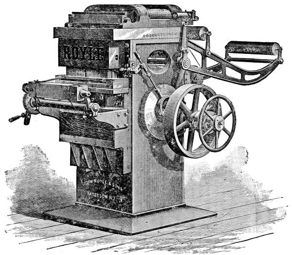
Fig. 25.
If several sets of cards of one design are required for starting a corresponding number of looms, and the first set has been produced by the “piano machine” exact duplicates can easily be obtained at small cost to the manufacturer by the “Repeating Machine.” This machine is built by Messrs. John Royle & Sons, Paterson, N. J., and is illustrated by Fig. 25 in a perspective view.
Fig. 26, p. 94, represents the front elevation of the throat-piece through which the cards that are to be cut pass, the carriage on which it is supported, and the mechanism employed for imparting a rising and falling motion to the carriage.
Fig. 27, p. 95, is a vertical longitudinal section of the upper portion of the machine.
Fig. 28, p. 95, gives a perspective view in detail of portions of a selecting-needle and key-wire and a lever connecting them.
Fig. 29, p. 95, gives a view in detail of the mechanism employed to turn the pattern cylinder.
The cards to be duplicated (N, N, Fig. 26, p. 94,) are arranged upon the card race-arms (M, M, Fig. 26,) in the same manner as upon a loom. The uncut or blank cards, having been previously laced together, (E, E, Fig. 26), are piled in the rear at the base of the column, and thence passed forward through the machine, and delivered finished in front.
The perforating of the cards is performed by a vertically reciprocating die, (D, Fig. 26), and a set of punches (C, Fig. 26,) carried in a fixed punch-head, and capable of being pushed upward when such movement is not prevented. The cards commonly used are of a size to receive 600 holes, and hence that number of punches are required.
The cards (E) to be cut are drawn over a “reel” or “idler” (F, Fig. 26,) at the back of the machine, and thence pass through openings in the base frame to the front of the machine, and over a square cylinder having a step-by-step rotary motion. By each quarter turn of this cylinder, the chain of cards is drawn forward sufficiently to bring a new card in the die. By the rising movement of the die (carriage), which takes place as soon as the intermittent feed of the cards has ceased, the card in the throat of the machine is carried up against the lower ends of the punches, and is cut or perforated by all such punches as have their upward movement prevented by the keys; while such punches as are not arrested by the keys are carried upward, and do not puncture the card. The pieces of card cut off fall through a throat or opening in the carriage (F, Fig. 27,) into the hollow base frame, (A, Fig. 27), and can be taken out at the door, (A, Fig. 26).
It will therefore be apparent that the variations in the cards are produced simply by holding down different punches in successive punching operations. This is regulated by the original set of cards, (N, Fig. 26), which are passed over the pattern cylinder (O, Fig. 26). The latter has also a step-by-step rotary motion similar to the cylinder first described. Its four faces are covered with holes the same distances apart as the perforations in the pattern cards. This pattern cylinder is mounted in bearings in a carriage on the top of the machine, and is reciprocated back and forth between the successive rotary movements of the feed and pattern cylinders.
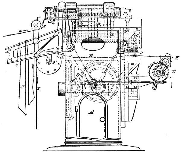
Fig. 26.
In the upper part of the machine are arranged what are termed selecting needles, (C, Fig. 27), which consist of wires arranged in horizontal rows, with their ends opposite to the pattern cylinder, and which are the same distance apart as the holes in the cylinder, so that if the cylinder were moved up by the carriage against the ends of the needles, the latter would enter the holes in the cylinder, and would not be moved longitudinally. There are the same number of selecting needles as punches in the machine—six hundred. When, however, a perforated pattern card is on the cylinder, and it is moved against the ends of the selecting needles, such needles as are opposite the perforations of the cards will enter them, and will not be moved, while such needles as are opposite the blank spaces of the cards will be moved longitudinally. [See Fig. 27 for illustration.] At the reverse movement of the carriage, an “evener,” which is secured to it at the end opposite the pattern cylinder, strikes against the ends of all the needles so moved and pushes them back to their original position. Above each of the punches before described is a horizontal sliding key (D, Fig. 27,) attached to a horizontal key-wire (D´, Fig. 27), and the 600 key-wires are arranged in horizontal rows below the selecting needles, and are each connected by a lever (B, Fig. 27,) with the corresponding selecting needle. Consequently, a longitudinal motion of any selecting needle will move the key-wire with which it is connected in a reverse direction.
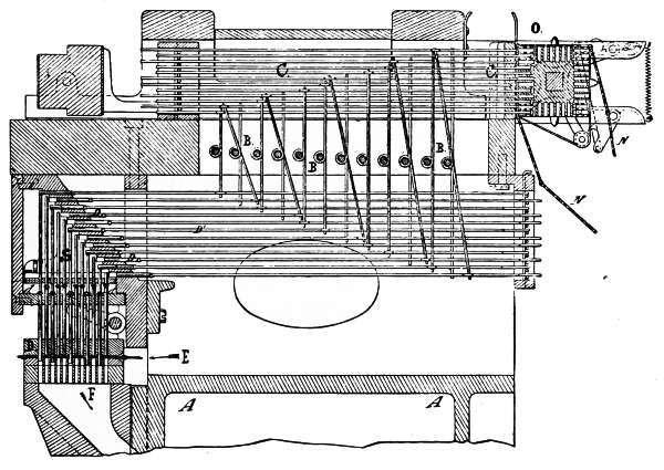
Fig. 27.
Fig. 28 gives a clear demonstration of the connection of a selecting needle, c, to the key-wire, f by means of the lever, e, movable around the fixed pin, d. Each key (D, Fig. 27,) consists of a cylindrical plug of metal, which, projecting over a punch, forms an abutment to keep that punch from rising, but if withdrawn, allows the punch to rise without resistance.
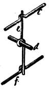
Fig. 28.
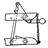
Fig. 29.
A step arrangement of the punches and keys is adopted; that is, the upper ends of the outer rows of punches are highest and the punches in the several rows decrease in height till the inner row is reached, where the punches are the lowest. Hence, the keys of the upper rows, which correspond to the outer rows of punches, are carried over the inner rows of punches and terminate over the punches in the outer rows.
Normally, all the keys are above the punches, and all would punch when the die ascends, but when a pattern card is carried by the pattern cylinder against the ends of the selecting needles, certain needles are moved and produce a reverse movement of the corresponding key-wires, and draws certain keys out of reach of their punches; no resistance being offered to the upward movement of such punches, they do not perforate the cards.
The carriage on which the pattern cylinder is carried being mounted directly on the top of the machine, can be readily lifted off to afford access to the parts below, and it is provided with a movable hood, which may be lifted to inspect the selecting needles.
The keys and key-wires are arranged farther apart vertically than the selecting needles, thus enabling larger keys and heavier and stronger key bearings to be used, and avoiding any liability of the punches striking the keys in the tier next above when those of their own tier are withdrawn.
Instead of applying a separate spring to each punch to move it downward or return it as the die recedes, a positively operated returning plate is used, which moves down as the die recedes and acts on collars on the punches, [see d, Fig. 27], and forces all the punches down. This is very important, for if any of the punches should fail to descend, the movement of their keys would be prevented, and thereby the machine would fail to properly repeat.
The bearings of the pattern cylinder are so constructed that the cylinder can be instantly changed to allow either a 400 or a 600-hole cylinder to be used, so that the bearings can be adjusted to adapt them for either size cylinder.
The bearings of the feed cylinder, whereby the chain of cards to be cut is moved, are constructed and supported so as to enable them to be readily adjusted to suit slight variations in the tightness with which the cards are laced, or in a greater degree to suit large or small cards, and the mechanism whereby the cylinder is operated is capable of ready adjustment for the same purpose.
It is well known that the punching of a great number of holes simultaneously, even in cardboard, requires great power, and entails enormous shock and great wear on the machine; to obviate this difficulty, the punches are slightly varied in length relative to their keys, so that they will not all act on the cards at exactly the same instant, and the strain on the machine and power required are thereby greatly reduced.
A Lace-Hole Press
Is indispensable to the machine. This is a separate little machine, designed to set upon a bench or table, and is used especially for cutting the peg and lace-holes. It may be operated very readily by hand, but if desired, is easily adapted to run by power. The feeding is done by one motion of the hand, and once handling of the card; the cards leave the press by gravitation, and arrange themselves in piles. The press is arranged to cut cards for 400 or 600 machines.