Illustrations of the Different Parts of the Jacquard Machine.—Method of Operation, etc.
Reading edition
Every Jacquard machine may be divided into the following parts:
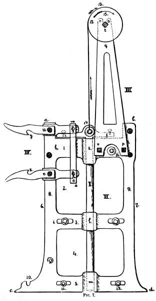
Fig. I.
1. The Frame and the Perforated Board through which the neck-cords are passed. 2. The Griffe and necessary attachments for lifting the same. 3. The Hooks. 4. The Needles. 5. The Springs and Spring Frame. 6. The Needle-board. 7. The Cylinder, Hammer, and Batten. 8. The Catches. 9. The Cards. 10. The Jacquard Harness.
THE FRAME.
Fig. I.,[A] represents the side view of the “frame” of a common 200 Jacquard machine by a, b, c, d. The width of the frame in its main part [see 6 to 7] is 9-1/2 inches.
1-1/8 inches is the width of the iron casting at the places marked 8 and 9.
2 inches is the height of casting at the place indicated by 1.
1-1/2 inches is the height of casting at the place indicated by 3.
1-3/4 inches is the height of casting at the place indicated by 5.
The open part of the frame, marked 2 in drawing, is 6 inches high.
The open part of the frame, marked 4 in drawing, is 5 inches high. Hence, the main height of the frame is as follows:
1 = 2 inches.
2 = 6 inches.
3 = 1-1/2 inches.
4 = 5 inches.
5 = 1-3/4 inches.
-------
16-1/4 inches main height.
THE PERFORATED BOARD.
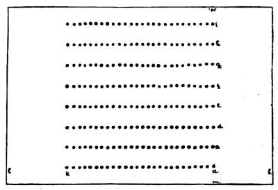
Fig. II.
The perforated bottom board, through which the neck-cords are passed, contains one hole for every hook in the machine, and is illustrated in Fig. II. separately. It shows the following measurements:
Entire width of board = 8 inches.
Entire length of board = 12 inches.
Thickness of board = 3/4 inches.
Distance of holes from each centre, {a, in length of board, 0.27 inch. (See l to b.)
{b, in width of board, 7/8 inch. (See m to w.)
Distance of first row from the part of the frame illustrated in Fig. I., 2-3/4 inches. Distance of first row from the rear part of the frame, 2-1/2 inches.
This board is fastened by screws to the frame at places indicated in Fig. I. by 11 and 12.
THE PLUNGER.
Besides the frame, Fig. I. illustrates: Under I. the Jacquard plunger, 3/4 inch diameter, for guiding the griffe (attached to its head) when raising. To strengthen the steadiness of this latter movement shoulders are attached to the frame at the three places where the plunger slides.
Height of frame at k, = 2-3/4 inches.
Height of frame at l, = 2 inches.
Height of frame at m, = 2 inches.
Screws, f, dotted in drawing, on head of plunger, fasten the griffe to it.
Part III. in Fig. I. illustrates the attachment for providing the lifting of the plunger in a hand-loom, likewise the griffe, etc. This consists of a triangular shaped frame 14-1/4 inches high, or less, according to height of room. This part is fastened to the front part of the frame by bolts at o and p. In the slot at the top, between r and s, a wooden cylinder of 3-1/2 inches diameter is fastened to an iron shaft resting in the frame at t.
At 13 a leather strap is fastened to this cylinder and to the plunger 14. It will easily be seen that by turning the wooden cylinder in the direction of the arrows, 15, the plunger will be raised with the griffe fastened to its top. By reversing the action of the cylinder, the plunger and griffe will return to their previous positions. The action thus described constitutes a “single lift,” raising and lowering of plunger and griffe for each pick.
THE CATCHES.
At IV., Fig. I., the “catches” for turning the cylinder at the lantern are illustrated. The distance of the centre of the screws which hold the catches to the frame is 4-3/4 inches. Between these two catches the cylinder is adjusted to the batten, and the direction of its turning is regulated by the catch which is brought in contact with the lantern. If the catch, y, turns, the cylinder will turn the card situated on its top towards the needle-board, and if catch, z, is brought into contact with the lantern, the card hanging below the needle-board will be the next in turn to be pushed towards the needles.
The entire length of the catches in the present illustration is 8 ins., allowing 5-1/4 ins. for the catch itself and 2-3/4 ins. for the part to which it is fastened. Making this catch in two pieces is preferable to the old style of one piece, because the moment of turning the cylinder can be more easily regulated.
THE GRIFFE.
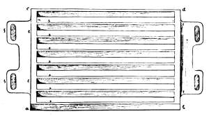
Fig. III.
Fig. III. illustrates the top view of the griffe. As mentioned before, the griffe is fastened to the plunger by means of screws. In the drawing the dark shaded places marked f are the hollow places in the griffe, through which the screws fasten the latter to the plunger. The griffe, like the other parts explained, is made of cast iron, and the machine is of the following dimensions:
Length of griffe, a to b, = 9-3/4 inches.
Depth of griffe, a to c,= 6-5/8 inches.
Extension on each side, e to f, = 1-1/2 inches.
Distance of griffe-bars, s to s, = 7/8 inch.
Length of griffe-bars, m to n, = 9-1/4 inches.
Height of griffe-bars, [see Fig. IV., sectional cut of griffe-bars,] = 7/8 inch. inches.
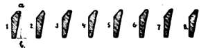
Fig. IV.
THE HOOK.

Fig. V.
Fig. V. represents a hook as used in the present machine, made of No. 13-1/4 bright spring wire. Height, a to c, = 16-5/8 inches. Height of rester, b to c, = 6-5/8 inches.
THE NEEDLE.
Fig. VI. illustrates a needle, as used in connection with the hook. Distance from head to loop, 9-1/8 inches, = a to c. Length of loop, 1-5/8 inches, = c to d. 10-3/4 inches entire length.

Fig. VI.
The distance from head to eye (for passing through the hook) is regulated according to the row in which the needle belongs. In the present illustration this is, Head to eye, = 7 inches, = a to b. The eye, = 3/8 inch, = b.
Eight different positions of the distance of the eye from head will be required by an 8-row machine. The needles are made of No. 15-1/2 bright spring wire. The loop on the end, c to d, permits a pin to be inserted, [see Fig. VII., o], and also holds the needle in position.
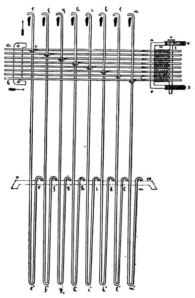
Fig. VII.
Fig. VII. gives a clear understanding of the arrangement of hooks, needles, griffe-bars, springs, frame for holding the latter, and the needle-board. This drawing is in accordance with the preceding ones, executed one-fourth of the actual size, and represents the sectional cut of one cross-row in the Jacquard machine containing 8 hooks, (as it is an 8-row deep machine which we explain): e to e´, 1st hook; f to f´, 2d hook; g to g´, 3d hook; h to h´, 4th hook; i to i´, 5th hook; k to k´, 6th hook; l to l´, 7th hook; m to m´, 8th hook. These hooks are held in their required places by the eyes of the needles [see place v at hook 1], through which the former are passed.
The needles rest with their heads in the needle-board, a to b, extending outside, towards the cylinder, for about 1/2 inch. The rear part of the needle—the loop—is passed between two bars of the spring frame, n, p, and held by the latter firmly, but with sufficient play for a longitudinal motion for pressing towards their springs. The pin, o, is inserted for holding the springs in their places. One pin is required for each vertical row of needles. The part of the spring frame, r, n, p, s, unshaded, is made of cast iron; the shaded part (extension) is constructed of wood. Below the upper crook of the hooks, the black sections represent a sectional cut of the griffe-bars; v to w indicates the rester for the lower hooks, which keeps the latter in their required position.
A study of this illustration will show that when the heads of the needles, a-b, are pushed backwards, in the direction of arrows, the hooks are also moved. If the needles are not pushed, the upper crooks of the hooks will remain in position, as in drawing, over the griffe-bar; and raising the latter will consequently raise every one of these hooks. Therefore, if a blank card is pressed against the 208 needles of the machine, all the needles and hooks will be pushed back, out of the way of contact with the griffe-bars, thus causing an empty lift when they are raised; whereas, by pressing with an empty cylinder, or with a card, containing as many holes as the machine has needles, and so placed that the holes are exactly opposite the needles, none of them would be moved, and each hook would remain vertical over its griffe-bar; and raising the griffe will lift every hook.
As mentioned before, the springs, u, are attached to the needles between the needle-frame, n-p, and the pin, o. Fig. VI., the distance e to f indicates the part of the loop around which the spring is adjusted, and where it rests against the expansion of the loop. f, in Fig. VI., represents the place where pin, o, (as shown in Fig. VII.) passes through the loop and is fastened to the needle-frame on top and bottom. Pressing the needle at the head compresses the spring, as the latter is securely fastened on one end by the wider part of the loop, and on the other end by a pin inserted in the loop and fastened to the frame. Remove the pressure at the head of the needle, and the spring will return to its natural position, pushing the needle into its old place. These springs are made of thin brass wire.
It is necessary to keep the needle-eyes in the proper place, otherwise it would result in bending the hook out of its perpendicular position, and by lowering the griffe its bars would possibly come in contact with the head of the hook, crushing the latter, or doing more damage if not detected at once. Each needle or hook, if worn out, can be replaced by pulling out the pin, o, thus loosening the needle and giving a chance to work the required hook out of the needle-eye.
THE BATTEN MOTION.
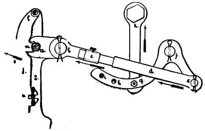
Fig. VIII.
Fig. VIII. represents the batten motion to be attached to the guiding-rod, [see No. 14, in Fig. I.], and the frame, [see No. 16, in Fig. I.] The batten, 2, is connected to a triangular lever by means of lever, d. Another vertical lever connects the lower part of this triangular lever to a projecting bolt, k, fixed to the guiding-rod of the griffe. By raising the guiding-rod, thus raising lever, k, in the direction of the arrow, the batten is thrown outwards, [see direction of arrow below c], returning again to its former position at the lowering of the griffe. f indicates the place where the triangular lever is fastened (movable) to the projecting bolt, extending out of the frame. a indicates the place for the cylinder. Part 1 of the batten is movable at l in the direction of arrow, s, allowing the cylinder to be inserted. Part 1 is fastened (after putting the cylinder in at a), to 2 by means of the screw, n.
THE CYLINDER.
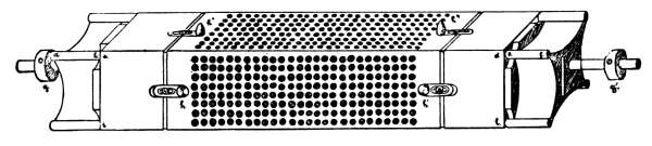
Fig. IX.
Fig. IX. represents the cylinder, with the lantern for turning the same by means of the catches. The dimensions for the cylinder in the present machine are as follows:
Height of cylinder,= 2-7/16 inches.
Width of cylinder,= 13 inches.
Width of lantern, = 1-1/2 inches.
Average length of spindle,= 2 inches.
This cylinder is carried in the batten, the latter moving in the groove provided for it under 10, Fig. I. This batten has sufficient vibratory motion to enable it to move the required distance away from the needle-board. After coming in contact with the catch it still moves until the cylinder has performed a complete turn. The cylinder is steadied in the required position by the hammer pressing by the means of a spring towards the lantern from below.
THE HAMMER.
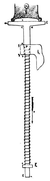
Fig. X.
Fig. X. illustrates the hammer as attached to the batten; a to b, (equals 3 inches in width in our present illustration), represents the head of the hammer, forming the foundation for steadying the cylinder in its turning. The hammer is pressed for this purpose towards the cylinder by means of the spring, s to r. Parts h and k guide the hammer in its up and down movements, and are solid parts of the batten. By turning the cylinder the hammer is pushed down in the direction of the arrow, t, thus compressing the spring, which returns to its normal position after the cylinder has completed its turn, ready for being advanced towards the needle-board.
The following are accurate measurements of this part of the machine:
Height of head of hammer at a and b,= 1/4 inch.
Thickness of hammer-head, e to c, = 3/8 inch.
Height of hammer-head when at rest above the top guiding part, c to o,= 1-1/2 inch.
Width of the guiding-rod, c to d, = 1/2 inch.
Thickness of “top guide,” f to g, = 3/4 inch.
Thickness of “lower guide,” f to r,= 1/4 inch.
Distance between these guides, = 9 inches.
Total height of guiding-rod, = 10-1/2 inches.
The shaded part of the drawing above the hammer represents the cylinder, i, which has its shaft for turning at m.
THE NEEDLE-BOARD.
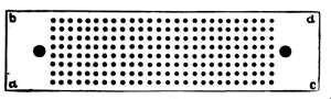
Fig. XI.
As before mentioned, the heads of the needles are passed through the needle-board. A drawing of this board, representing the front view, is shown in Fig. XI. The following are the dimensions:
a to c, = 9-1/2 inches. a to b, = 2-3/8 inches.
Each side of the prism, always technically called the cylinder, has a protruding peg about 1/2 inch in length. When in contact with the needle-board these pegs enter the black holes shown upon either side in drawing. The 208 needles and holes in the present machine are represented by a small spot for the former with an outside ring for the latter.
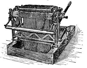
Fig. XII.
The lifting of the griffe, which in turn also operates the other parts of the Jacquard head, as explained before, is not always produced from above: very often this lifting is arranged to be done by means of a lever arrangement from below the griffe. This method of working the mechanism in the Jacquard machine is illustrated by Fig. XII., representing the perspective view of a 400 Jacquard machine, (W. P. Uhlinger, builder).
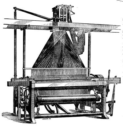
Fig. XIII.
Fig. XIII. represents the same machine adjusted to the loom. On the longer arm of the lever a series of holes are found. These regulate the height of the lift by the vertical rod which provides the required movement. The nearer this rod is adjusted to the Jacquard head the higher the lift of the Jacquard harness, thus forming the shed.
THE JACQUARD CARDS.
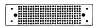
Fig. XIV.
Fig. XIV. represents a single Jacquard card, as required for the 200 Jacquard machine, 1/4 of its actual size. This shows 26 rows of holes in its width and 8 rows in its depth, 208 holes. These holes are shown in black, one for each hook in the machine. Besides these a large hole on each side permit the pegs of the cylinder to enter into the needle-board. The cards are interlaced in an endless arrangement.
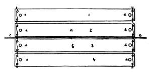
Fig. XV.
Fig. XV. illustrates four cards laced together. The large holes (marked d in drawing) are peg holes to receive the pegs, h, h´, h´´, h´´´, etc., of the cylinder, as shown in Fig. IX. These pegs are movable so that any small variations at cutting with different card-stamping machines can be rectified. The paper used for the cards must be of sufficient thickness to resist the wear caused by the needles, as well as to give steadiness to the cards when resting in the pegs of the cylinder.
The cards are interlaced in an endless arrangement; hence, one card is brought after the other in rotation towards the needles. The cards only refuse service by not fitting properly on the cylinder, i. e., if the peg holes are too near together or too far apart; or if the cards are warped, which is liable to happen in a damp workshop.
A careful examination of the cards fitting on the cylinder is absolutely necessary, otherwise a wrong lifting of the hooks destroying the cards by the pegs punching new holes would result. The cylinder with cards perfectly cut must be set so as to allow the needles to penetrate into the centre of the holes stamped for them in the card. Sometimes the cylinder is set too high or too low—too far in front or too far in rear. To ascertain the proper position, lift the machine and place some paint, or grease from the machine, on the heads of the needles. Afterwards let the machine “fall in,” which will bring the cards against the heads of the needles, producing an impression and indicating the exact position of the needle-heads. The cylinder is always set in its proper position when no marks are made by the entering needles on the margins of the stamped holes and where there are no holes the impression left by the needle head must be equally distant from the surrounding holes.
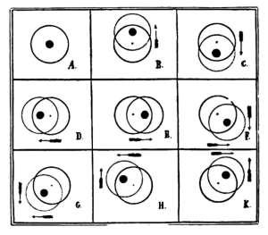
Fig. XVI.
To get a clear understanding of this examine Fig. XVI. illustrating six different impressions of the needles. The circle shown with full lines in each of these six illustrations represents the correct position of the circumference of the hole, and the dotted circles the various errors that may exist.
Fig. A shows the cylinder set in its proper place, which is indicated by the impression of the needle in the centre.
Fig. B shows the cylinder is set too high, as indicated by the impression of the needle. [See arrow.]
In Fig. C the cylinder is set too low.
In Fig. D the cylinder is set too far to the left.
In Fig. E the cylinder is set too far to the right.
In Fig. F the cylinder is set too low and too far to the right.
In Fig. G the cylinder is set too low and too far to the left.
In Fig. H the cylinder is set too high and too far to the left.
In Fig. K the cylinder is set too high and too far to the right.
If the machine produces wrong lifts of the hooks and the trouble is not found in the setting of the cylinder, nor in the hooks or needles, then ascertain if the cylinder is adjusted by means of the lever arrangement, close enough to the needle-board; for if it is not, the hooks will not be pushed far enough from the griffe-bars, and by raising the latter a wrong shed will be produced. When using a great number of cards in a set they are made to fold into a “rack.” This is done by attaching a wire 1 to 1-1/2 inches longer than the cards at the junction of, say every 12th, 15th, or 20th cards. [See c at Fig. XV.]
The cards fall through a wooden frame, Fig. XVII., but the wires attached to the cards, being longer, can not pass through, and the cards will remain suspended, and subsequently fold together in a very compact manner.
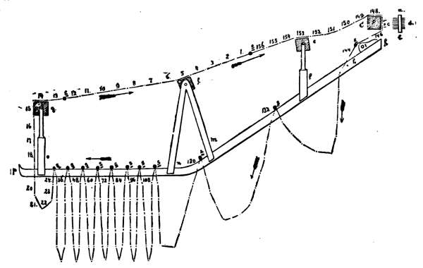
Fig. XVII.
In Fig. XVII. we illustrate 156 cards arranged with wires attached to every twelfth card, as follows: between cards 156 and 1, 12 and 13, 24 and 25, 36 and 37, 48 and 49, 60 and 61, 72 and 73, 84 and 85, 96 and 97, 108 and 109, 120 and 121, 132 and 133, 144 and 145.
At e, f, g, are shown prisms of the size of the cylinder, by which the cards are guided and regulated in their run towards the cylinder, (direction of arrow); i and h represent round rollers, also placed in rack for guiding cards after leaving the cylinder, c; a and b, the needle-board; c and d, the needles of the machine. S represents the wires as inserted in cards for holding them in the frame.