Front matter
Reading edition
Compiler's Notes
Paper 34 Paper 35 Paper 36 Paper 37 Paper 38 Paper 39 Paper 40 Paper 41 Paper 42 Paper 43 Paper 44
Transcriber's Notes for each Paper and the Index follows the text of that Paper/Index.
SMITHSONIAN INSTITUTION
UNITED STATES NATIONAL MUSEUM
BULLETIN 240
SMITHSONIAN PRESS
MUSEUM OF HISTORY AND TECHNOLOGY
Contributions From the Museum of History and Technology Papers 34-44 On Science and Technology
SMITHSONIAN INSTITUTION · WASHINGTON, D.C. 1966
Publications of the United States National Museum
The scholarly and scientific publications of the United States National Museum include two series, Proceedings of the United States National Museum and United States National Museum Bulletin.
In these series, the Museum publishes original articles and monographs dealing with the collections and work of its constituent museums—The Museum of Natural History and the Museum of History and Technology—setting forth newly acquired facts in the fields of anthropology, biology, history, geology, and technology. Copies of each publication are distributed to libraries, to cultural and scientific organizations, and to specialists and others interested in the different subjects.
The Proceedings, begun in 1878, are intended for the publication, in separate form, of shorter papers from the Museum of Natural History. These are gathered in volumes, octavo in size, with the publication date of each paper recorded in the table of contents of the volume.
In the Bulletin series, the first of which was issued in 1875, appear longer, separate publications consisting of monographs (occasionally in several parts) and volumes in which are collected works on related subjects. Bulletins are either octavo or quarto in size, depending on the needs of the presentation. Since 1902 papers relating to the botanical collections of the Museum of Natural History have been published in the Bulletin series under the heading Contributions from the United States National Herbarium, and since 1959, in Bulletins titled “Contributions from the Museum of History and Technology,” have been gathered shorter papers relating to the collections and research of that Museum.
The present collection of Contributions, Papers 34-44, comprises Bulletin 240. Each of these papers has been previously published in separate form. The year of publication is shown on the last page of each paper.
Frank A. Taylor Director, United States National Museum
Papers
Page
34. The 1893 Duryea Automobile Don H. Berkebile 1
35. The Borghesi Astronomical Clock Silvio A. Bedini 29
36. The Engineering Contributions of Wendel Bollman Robert M. Vogel 77
37. Screw-Thread Cutting by the Master Screw Method Since 1480 Edwin A. Battison 105
38. The Earliest Electromagnetic Instruments Robert A. Chipman 121
39. Fulton’s “Steam Battery”: Blockship and Catamaran Howard I. Chapelle 137
40. History of Phosphorus Eduard Farber 177
41. Tunnel Engineering—A Museum Treatment Robert M. Vogel 201
42. The “Pioneer”: Light Passenger Locomotive of 1851 John H. White 241
43. History of the Division of Medical Sciences Sami Hamarneh 269
44. Development of Gravity Pendulums in the 19th Century Victor F. Lenzen and Robert P. Multhauf 301
Produced by Colin Bell, Joseph Cooper, Stephanie Eason, and the Online Distributed Proofreading Team at http://www.pgdp.net.
Contributions from The Museum of History and Technology: Paper 34 The 1893 Duryea Automobile In the Museum of History and Technology
Don H. Berkebile
EARLY AUTOMOTIVE EXPERIENCE 5
CONSTRUCTION BEGINS 6
DESCRIPTION OF THE AUTOMOBILE 16
INDEX
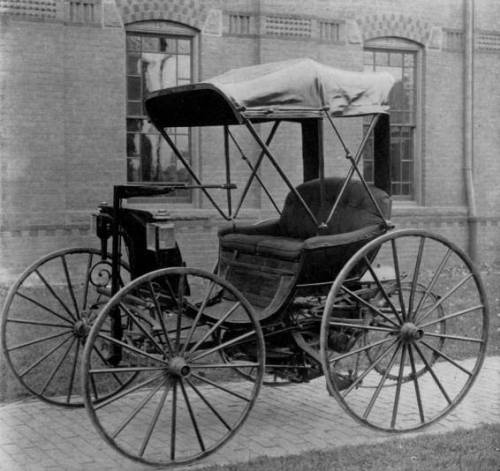
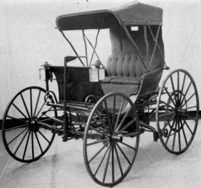
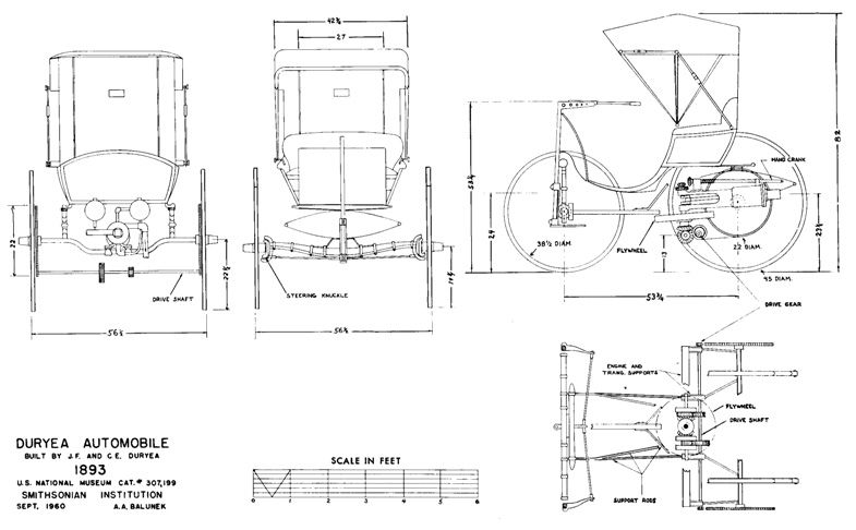
Figure 1.—Duryea automobile in the Museum of History and Technology, from an 1897 photograph. The gear-sprockets were already missing when this was taken, and the chain lies loosely on the pinion. Shown at the right, the Duryea vehicle following the recent restoration (Smithsonian photo 34183).
Don H. Berkebile
THE 1893 DURYEA AUTOMOBILE
In the Museum of History and Technology
During the last decade of the nineteenth century a number of American engineers and mechanics were working diligently to develop a practical self-propelled vehicle employing an internal-combustion engine as the motive force. Among these men were Charles and Frank Duryea, who began work on this type of vehicle about 1892. This carriage was operated on the streets of Springfield, Massachusetts, in 1893, where its trials were noted in the newspapers. Now preserved in the Museum of History and Technology, it is a prized exhibit in the collection of early automobiles.
It is the purpose of this paper to present some of the facts discovered during the restoration of the vehicle, to show the problems that faced its builders, and to describe their solutions. An attempt also has been made to correlate all this information with reports of the now almost legendary day-to-day experiences of the Duryeas, as published by the brothers in various booklets, and as related by Frank Duryea during two interviews, recorded on tape in 1956 and 1957, while he was visiting the Smithsonian.
The Author: Don H. Berkebile is on the staff of the Museum of History and Technology, in the Smithsonian Institution's United States National Museum.
Of the numerous American automotive pioneers, perhaps among the best known are Charles and Frank Duryea. Beginning their work of automobile building in Springfield, Massachusetts, and after much rebuilding, they constructed their first successful vehicle in 1892 and 1893. No sooner was this finished than Frank, working alone, began work on a second vehicle having a two-cylinder engine. With this automobile, sufficient capital was attracted in 1895 to form the Duryea Motor Wagon Company in which both brothers were among the stockholders and directors. A short time after the formation of the company this second automobile was entered by the company in the Chicago Times-Herald automobile race on Thanksgiving Day, November 28, 1895, where Frank Duryea won a victory over the other five contestants—two electric automobiles and three Benz machines imported from Germany.
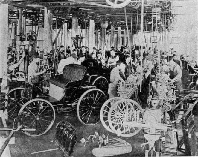
Figure 2.—Workmen in the Duryea factory in Springfield, Mass., working on some of the thirteen 1896 motor wagons. (Smithsonian photo 44062.)
Frank, in 1901, entered into a contract with the J. Stevens Arms and Tool Company, of Chicopee Falls, Massachusetts, which built automobiles under his supervision. This association led in 1904 to the formation of the Stevens-Duryea Company, of which Irving Page was president and Frank Duryea was vice president and chief engineer. This company produced during its 10-year existence a number of popular and well-known models, among them a light six known as the Model U, in 1907; a larger 4-cylinder called the Model X, in 1908; and a larger six, the Model Y, in 1909. In 1914 when Stevens withdrew from the company, Frank obtained control. The following year he sold the plants and machinery, liquidated the company, and, due to ill health, retired.
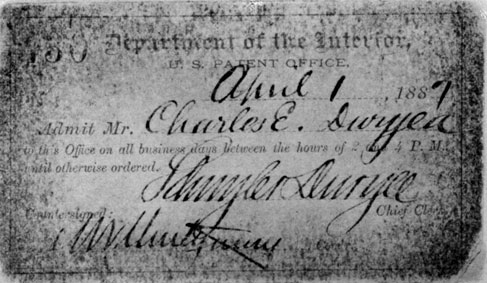
Figure 3.—Admittance card of C. E. Duryea to the U.S. Patent Office, 1887. (Gift of Rhea Duryea Johnson.)
Early Automotive Experience
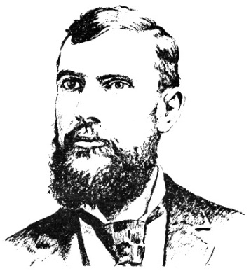
Figure 4.—Charles E. Duryea, about 1894, as drawn by George Giguere from a photograph. (Smithsonian photo 48335-A.)
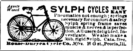
Figure 5.—Advertisement of Duryea bicycle company, Scientific American, September 9, 1893.
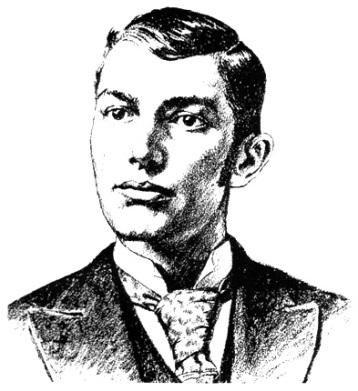
Figure 6.—J. Frank Duryea, about 1894, as drawn by George Giguere from a photograph. (Smithsonian photo 48335.)
Construction Begins
In motors hitherto used the fly-wheels have been attached to a horizontal shaft or axle, and have thus been made to revolve in a vertical plane, since the horizontal shaft is best adapted to the transmission of power. If, however, in this case we should use a heavy rotating mass, corresponding to the power employed and revolving rapidly in a vertical plane, the power to manage the vehicle or boat would become very much lessened, as the flywheel continues to revolve in its plane. I therefore so design the apparatus that its crank shaft x has a vertical position and its fly-wheel y revolves in a horizontal plane…. By this means the vehicle is not only easily controlled, but also the greatest safety is attained against capsizing.
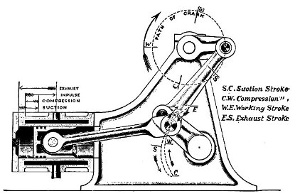
Figure 7.—Drawing showing principle of the Atkinson engine; this feature is what the Duryeas were trying to achieve with their free-piston engine, by substituting the free piston for the unusual linkage of the Atkinson. (Smithsonian photo H3263-A.)
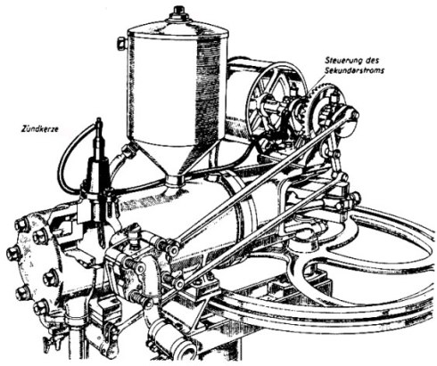
Figure 8.—Drawing of 1885 Benz engine, showing similarity in general appearance to Duryea engine. From Karl Benz und sein Lebenswerk, Stuttgart, 1953. (Daimler-Benz Company publication.)
The Ames plant customarily had a summer shutdown during August; thus, during August of 1891 Charles and Frank had access to a nearly empty plant in which they could carry on experiments and make up working drawings of the proposed vehicle. It cannot now be conclusively stated whether any parts were made for the car during August or the remainder of the year. It is more likely that the brothers attempted to complete a set of drawings. Frank Harrington, chief draftsman at Ames, may have helped out at this time; from Charles' statement of April 14, 1937, it is learned that he did prepare drawings during 1892.
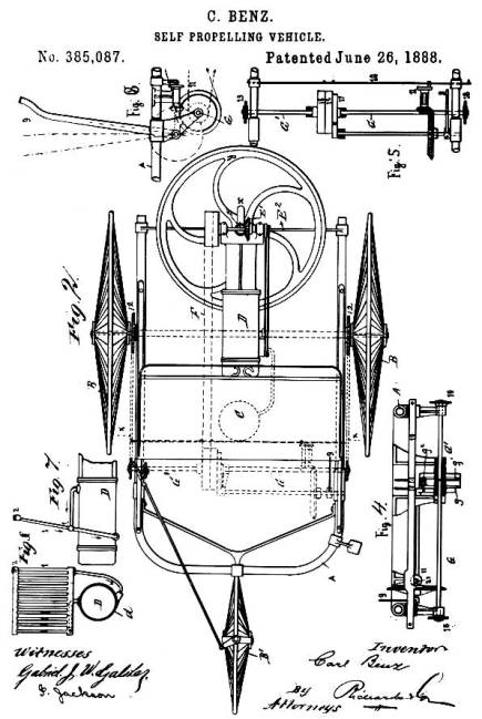
Figure 9.—Illustration from U.S. patent 385087, issued to Carl Benz, showing the horizontal plane of the flywheel, a feature utilized by the Duryeas in their machine.
The first contemporary record of any work on vehicles is a bill, dated January 21, 1892, for a drawing made by George W. Howard & Company. This drawing was made in the fall of 1891 by Charles A. Bartlett, a member of the Howard firm and a neighbor of Charles Duryea, according to a statement by Charles in the Automobile Trade Journal of Jan. 10, 1925. He was then also of the opinion that this drawing may not have had anything to do with the carriage they were about to assemble, but a notation found by Charles at a later date has led him to believe that it possibly concerned a business type vehicle he had discussed with an unidentified Mr. Snow.
By early 1892 Charles needed capital to finance his venture, an old carriage to attach his inventions to, a place to work, and a mechanic to do the work. On March 26, he stopped by the Smith Carriage Company and looked over a selection of used buggies and phaetons. He finally decided on a rather well-used ladies' phaeton which he purchased for $70. The leather dash was in so deplorable a state it would have to be recovered before the carriage went onto the road, and the leather fenders it once possessed had previously been removed; yet the upholstery appeared to be in satisfactory condition, and the candle lamps were intact.
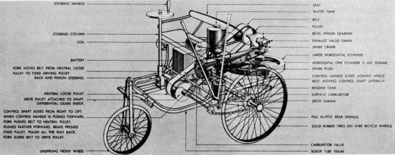
Figure 10.—Phantom illustration of Benz' first automobile. (From Carl Benz, Father of the Automobile Industry, by L. M. Fanning, New York, 1955.)
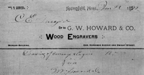
Figure 11.—The Howard & Co. bill showing the first work performed toward a motor vehicle. While this may not refer specifically to the machine now in the museum, it is evidence of early work.
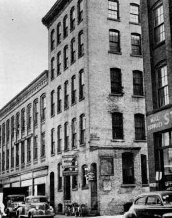
Figure 12.—The shop of John Russell & Sons. It was on the second floor of this building that Charles and Frank Duryea built their first motor vehicle. (Courtesy of the Springfield Union.)
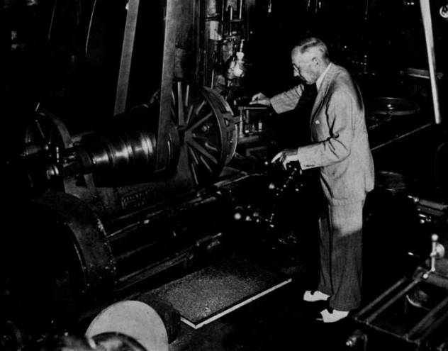
Figure 13.—J. Frank Duryea looking over the Russell shop lathe on which he turned parts for the first Duryea vehicle. Photo taken about 1944. (Courtesy of the Springfield Union.)
It is Frank Duryea's remembrance that he started work on Monday, April 4. He first removed the body, with its springs, and placed it on a pair of wooden horses where it remained until the summer of the following year. The next step was to remove the rear axle and take it to a blacksmith shop where the old axle spindles were cut off and welded to a new drop-center axle. Following this the front axle spindles were removed, the ends of the axle slotted, and a webbed, C-shaped piece carrying the kingpin bearings was fitted into each slot, braced from underneath by short brackets which were riveted and brazed in place. The old spindles then were welded to the center of offset kingpins which in turn were mounted in their bearings in a manner similar to that in which the frame of the Columbia high-wheeled bicycle was mounted in its fork. Arms welded to the lower end of the kingpins were connected by the tie rods to an arm on the lower end of the vertical steering column, located on the center of the axle.
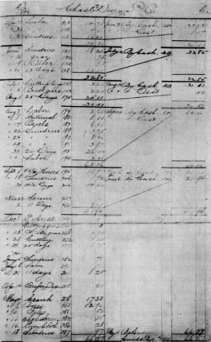
Figure 14.—A portion of the Russell shop records showing charges made against Charles Duryea during 1893-1894.
As no ignition system had yet been provided, they prepared a 4½-inch length of one-quarter inch iron pipe, closed at one end, and screwed the open end into the head. Heating this tube with an alcohol burner would cause ignition of the mixture when a portion of it was forced into the heated tube toward the end of the compression stroke. No attempt was made at this time to use the electrical make-and-break circuit used in their second engine, as the free piston would have wrecked the igniter parts on the exhaust stroke, and the push rod located on the end of the piston would have prevented the piston from closing the exhaust valve.
After keying the flywheel to the lower end of the crankshaft, Charles and Frank decided to make an attempt to run the engine. Carrying it into a back room, probably during July or August, 1892, they blocked it up on horses. A carburetor had not yet been constructed, so they attempted to start the engine by spinning the flywheel by hand, at the same time spraying gasoline through the intake valve with a perfume atomizer previously purchased at a drugstore in the Massasoit House. Repeated efforts of the two men to start the engine resulted in failure.
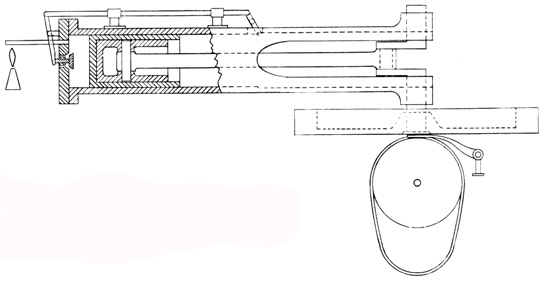
Figure 15.—Conjectural drawing of the free-piston engine used in the Museum vehicle prior to the present engine. (Drawing by A. A. Balunek.)
In the belief that the defects, whatever they might be, could be remedied after the engine was installed, the Duryeas went ahead and mounted the engine in the carriage. To do this they shortened the original reach of the carriage, allowing the engine itself to become the rear continuation of the reach. The four ears on the front, or open end of the engine, were bolted to the centrally located frame, with the bearing blocks in between. This frame, the same one now in the vehicle, was constructed of two pieces of angle iron, riveted and brazed together. Greater rigidity was obtained by a number of half-inch iron rods running from the frame to both front and rear axles. Because of the absence of any mounting brackets on the engine casting itself, a wooden block with a trough on top to receive the body of the engine was fitted between the engine and the axle, while two U-shaped rods secured it with clip bars and nuts underneath.
Beneath the flywheel was mounted the friction transmission of Charles' design. This consisted of a large drum, perhaps 12 inches in diameter, equal in length to the diameter of the flywheel and keyed to a shaft directly under the center of the crankshaft and parallel to the axles. (Diameter of drum estimated by examination of existing features.) In view of the four projections of the frame extending downward and just in front of the jackshaft position, it is likely that these supported the four jackshaft bearings. Being a bicycle manufacturer, Charles saw the need for a differential or balance gear. Accordingly, he purchased from the Pope Manufacturing Company a very light unit of the type formerly used on Columbia tricycles, and installed it somewhere on the jackshaft. A small sprocket on each end of the shaft carried a chain from the larger sprockets clamped to the spokes of each rear wheel. The lower surface of the flywheel had been machined so as to form a friction disc, with a one-quarter inch depression 3 inches in diameter turned in the center. The drum was positioned so that its upper surface was one-quarter inch below the face of the flywheel. Hanging loosely around the drum was an endless belt, one and one-half inches wide, first made of rather soft rubber packing material. The belt lay on the drum surface between the fingers of a shipper fork. While it lay under the 3-inch depression in the center of the flywheel, the belt and the drum were at rest, but when it was moved away from that depression the belt wedged itself tightly between the drum and flywheel, the resulting friction causing the drum to turn and setting the vehicle into motion. The farther the belt was moved toward the outer edge of the wheel, the faster the drum and the vehicle moved.
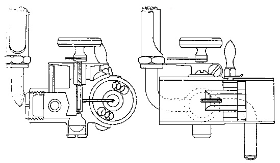
Figure 16.—Drawing of the carburetor used on both Duryea engines, 1893-1894, showing sight feed on left and choke mechanism on right. (Smithsonian photo 13455.)
Turning now to an efficient burner for heating the ignition tube, Frank started with an ordinary wick-type kerosene lamp with a small metal tank. Wishing to use gasoline in the lamp, he found it necessary to fabricate a number of burner units before he found a type that gave him a clean blue flame. He then found the flame to be very sensitive to drafts and easily extinguished, and devised a small shield or chimney to afford it some protection.
Early in October, while still working with the burner, Frank developed a severe headache. He felt the fumes of the lamp had probably caused it, and went to his room in the home of a Mr. and Mrs. Patrick on Front Street in Chicopee. After he noticed no improvement, a doctor's examination showed he had typhoid fever, and on October 5 he was admitted to the Springfield Hospital. Here he remained for one month, being discharged on November 5. Returning to his room he was informed that because of the fear that he might be a typhoid carrier, the Patricks preferred him to find other lodgings. He readily accepted the invitation of Mr. and Mrs. D. H. Nesbitt of Chicopee to take a room with them. After several weeks recuperation in their home, he left Springfield to visit his mother in Wyoming, Illinois.
Frank, hoping at last to be rewarded for his efforts by the sound of explosions from the engine, was ready to give the carriage an indoor trial. Standing astraddle of the reach and facing to the rear, he spun the flywheel with both hands, taking care not to get his hands caught between the wheel and the frame. His efforts were in vain, as there was complete failure to obtain ignition. He then made a new ignition tube, nearly twice as long as the original 4-½-inch tube, and turned down its wall as thin as he thought safety allowed. The thinner wall did not conduct the heat off so rapidly and thus kept the tube hot enough to permit ignition. After this slight change, he was able to get a few occasional explosions but he does not now believe that the engine ever operated continuously. Each explosion was accompanied by a loud knock, due, undoubtedly, to the movement of the free piston. Had the engine operated continuously, it is likely that the action of the free piston would have shortly wrecked the engine. Further efforts appeared unwarranted until alterations could be made.
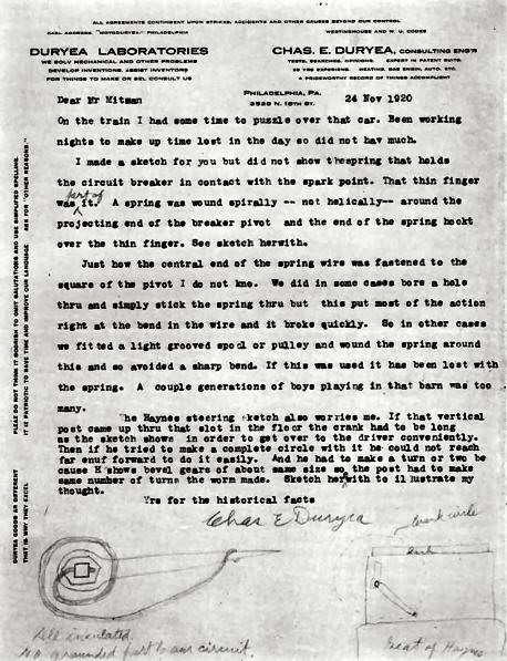
Figure 17.—Letter explaining the circuit breaker spring and the brass projection on top of the ignition chamber. Mr. Mitman was, at the time, curator of engineering in the U.S. National Museum. View Larger Image of Letter Text of Letter
The two pistons were first pinned together into a single unit which was probably ringless, since it is believed the walls of the outer piston were too thin to admit rings. Because the piston no longer struck the exhaust valve, a short rod had to be screwed into the pistonhead; this pushed the valve shut at the completion of the exhaust stroke. The remaining problem, the opening of the exhaust valve, was solved by screwing a device to the side of the cylinder which operated from the sidewise motion of the connecting rod. This device shifted a small spacer between the piston and the striker arm of the exhaust-valve rod, permitting the piston to push open the exhaust valve. On alternating strokes the spacer shifted back out of the cylinder; therefore, no contact was made between piston and striker arm. Sometime in February 1893, the altered engine was successfully started.
At last the transmission could be tested. Will Russell had come upstairs to watch the trial, and according to a statement by him, given April 30, 1926, Frank, standing to the right of the engine and behind the rear axle, reached forward and with the combination tiller-belt-shifter, moved the belt into driving position. The carriage started forward, but as it approached the wall of the building Frank discovered that he could not get the belt back into the neutral position. In desperation, he grasped the rear axle with both hands and was dragged a short distance, attempting to stop the machine, before it struck the wall. He had, however, sufficiently retarded it so that no damage was done.
This short trial demonstrated some of the weaknesses in the friction transmission. Since the speed of the surface of the flywheel, in feet per second, increased in proportion to the distance of the point of contact from the center, the outer edge of the belt attempted to run faster than the inner edge. This conflict of forces not only put an undue load on the motor causing a great loss of power, but it also created a tendency for the belt to work towards the outer edge of the flywheel. Conversely, when the operator desired to return the belt to neutral, it strongly resisted any efforts to slide it toward the center of the wheel, as Frank had learned from the wall-bumping incident. Furthermore, the rubber belt on the friction drum had worn so badly that it had to be replaced at least once during the brief experiments.
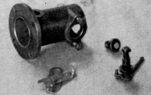
Figure 18.—Ignition chamber, switch, and breaker contacts of the present Duryea engine.
At this point, Frank and Markham felt that the carriage was anything but satisfactory. While they were trying to decide what steps should be taken next, Frank added one last improvement to the engine. Fearing that the uncooled cylinder might suffer damage from the excessive heat, he constructed a copper water jacket in two halves, drew them together around the cylinder with clamping rings and soldered the seams. Asbestos packing sealed the end joints where the jacket contacted the cylinder. Thinking back, Frank does not recall that he ever used a water tank with this engine, though he does remember adding water through the upper jacket opening. The engine was run only for a few brief periods following this addition.
Description of the Automobile
The engine castings were undoubtedly received from the foundry prior to Frank Duryea's marriage, and the work of machining and assembling the parts went on through the spring and summer. This engine, still on the carriage in the Museum of History and Technology, is cased with a water jacket, and has bases on top to support the front and rear bearings of the starting crankshaft, and a base with port on the upper right side where the exhaust-valve housing was to be bolted. On the underside are two flanges, forming a base for seating the engine on the axle. A separate combustion chamber is cast and bolted to the head. Inside this chamber are located the igniter parts of Frank's electric ignition system. The fixed part, an insulated electrode, is screwed into the right side of the chamber and is connected with the ignition switch outside, to which one of the ignition wires is attached. A breaker arm inside is pinned to a small shaft extending through the top of the chamber. Around the breaker-arm shaft is a small coil spring (originally a spiral spring, according to the letter of Charles Duryea shown in fig. 17), anchored below to a thin brass finger extending toward the right side of the car, and above to a nut screwed tightly onto the shaft. This nut is also the terminal for the other ignition wire. The action of the spring keeps the breaker arm and the electrode in constant contact until the push rod on the end of the piston strikes the arm and separates the two parts. Breaking contact then produces the ignition spark. Since the mechanism would spark at the end of both the exhaust and compression strokes, the battery current is conserved by a contact strip, on the underside of the larger exhaust-valve gear, by means of which the flow of current is cut off during the greater part of the cycle.
On the left side of the combustion chamber is bolted the housing containing the tiny intake valve. A comparatively weak spring seats this valve in order that the suction created by the piston can easily pull it open. Clamped onto the valve housing is the intake pipe, enclosing the choke and carrying the carburetor on its forward side. The choke consists of two discs which block the pipe, each with four holes at the edges and one in the center. Turning one disc by means of a small handle outside, so that the four outer holes cannot coincide with those in the other disc, decreases the flow of air and causes all air to rush through the center hole, where the tiny carburetor tube passes through. The present carburetor was transferred over from the first engine. When Frank later installed the engine on the carriage he noticed the close proximity of the intake pipe to the open end of the muffler. Believing that the fumes might choke the engine, he attached a long sheet-metal tube to the intake pipe so that fresh air would be drawn in from a point farther forward on the vehicle.
Moving to the right side of the engine brings the exhaust-valve assembly into view. This valve is contained in a casting bolted over the exhaust port in the side of the cylinder, and from the casting a pipe leads to the muffler underneath. The valve is pushed open by a rod connected to a crank which is pinned to the lower end of a shaft carrying an iron gear on top. This gear is in mesh with a fiber gear, keyed to the upper end of the crankshaft, with half the number of teeth. This ratio permits the opening of the exhaust valve on every other revolution.
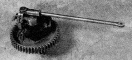
Figure 19.—Under side of exhaust valve mechanism showing electrical contacts that give spark only on every other revolution.
Just on top of the flywheel, and surrounding the crankshaft, rest two rings, 3⅞ inches in diameter. Into the opposing surfaces of these rings are cut a series of small inclined planes, appertinent to each other. On the outer circumference of the upper ring two pins pass through a pair of lugs mounted in the flywheel, causing the ring to rotate with the flywheel, yet permitting vertical movement. Underneath, the other ring is allowed to turn slightly when, by means of two connecting links, the arms of the governor push against them. These two arms, each constructed like a right angle and pivoted at the apex, are arranged directly opposite each other far out in the flywheel recess. As a weight on one angle of the arm presses outward by centrifugal force against a spring, the other angle presses inward against the connecting link mentioned above. The turning of the lower set of inclined planes against the fixed set above raises the upper ring and the fork resting on it. The upward movement of this fork, which is a continuation of an arm pivoted to a bracket midway between the crankshaft and the slide carrying the exhaust valve stop, causes the other end of the arm to drop, pulling the slide down with it. In this manner the closing of the exhaust valve is blocked, preventing the intake of the next charge, and therefore the engine misses one or more explosions until it slows to its normal speed.
A starting shaft is mounted above the engine casting by a cast-iron bracket on either end. The front end of the shaft has a bevel gear which is held by a coil spring behind the front bracket, just out of contact with a bevel gear pressed onto the upper end of the crankshaft. The short rear portion of the shaft is a tube which slides over the main shaft. Fitting the removable handcrank to the squared end of the hollow shaft and turning the crank clockwise, will advance the forward section of shaft through the medium of a pair of inclined collars. With the bevel gears now engaged the engine may be cranked. When ignition begins, the inclined collars slide back down each other's surfaces, the shaft is again shortened, and its bevel gear springs free of the one on the crankshaft.
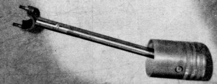
Figure 20.—Piston and connecting rod of second engine. Screw on rod is where oil is poured into connecting rod to lubricate wrist pin and crankshaft.
Frank next calculated that with the faster running engine the speed of the vehicle would be about 15 miles an hour, too much for the heavily loaded wheels. As he intended to make use of the original transmission, he decided to decrease the speed by increasing the size of the friction drum. He accomplished this by sliding a heavy fiber tube over the original drum, bringing its diameter to approximately 14 inches. The original shipper fork carriage was improved by separating the original bearings to a greater distance, and eliminating one of the two bearings on one end. This permitted a smooth and free operation of the small sliding carriage.
These little internal-gear sprockets were hung on double-shrouded pinions secured to each end of the jackshaft. A solid disc or housing fitted against both ends of the pinion to prevent the internal gear from working off sideways. Duryea explained the function of these unique little parts: "as soon as tension came on that ring gear that we talked about, it not only tightened the chain hanging on this sprocket on the upper side, but it tightened it on both sides. [The sprocket] rocks right out: both sides of the chain are tight."
This feature is one rarely encountered elsewhere, and Duryea, later in the interview said, "To tell you the truth, I think I was just a little bit ashamed about the thing, because I had to pull it off. I didn't like the looks of it after I got it on."
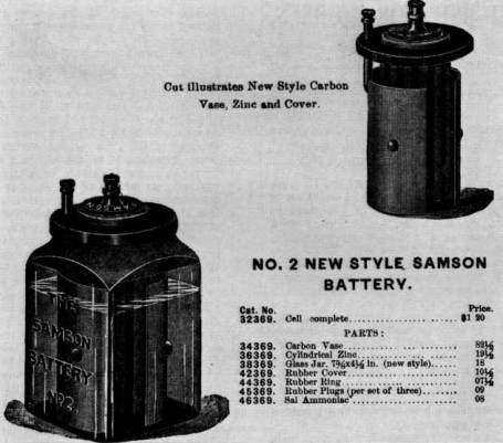
Figure 21.—Illustration of the no. 2 Samson battery used by the Duryeas in their vehicle. (Smithsonian photo 46858.)
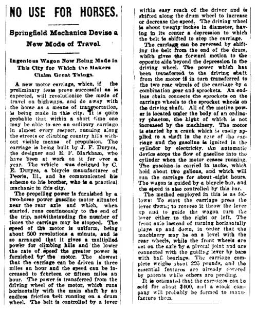
Figure 22.—From the Springfield Evening Union, September 16, 1893. Text of Article
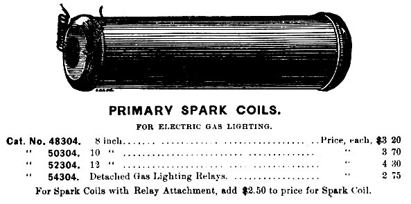
Figure 23.—Type of spark coil the Duryeas are believed to have used in their electrical circuit, as shown in a catalog illustration. (Smithsonian photo 46858-A.)
The Springfield Evening Union of September 22 carried a notice of the trial. This report, too, commented on the faulty transmission and the plan already in Frank's mind for the new transmission.
… The friction belt allowed of the speed being steadily increased or diminished at the will of the driver and caused no sudden forward motion of the carriage, but while this arrangement has many advantages it uses up the power so that the two-horse power furnished by the motor [somewhat less than the rating Frank gave the engine] was reduced to less than three-fourths horse power on reaching the main shaft. This would not be sufficient to propel the carriage up steep grades but would be sufficient to run the carriage on level road.
The inventors will do away with this belt in favor of a clamp gear and will make the drum wheel smaller. By this means there will be very little power lost in transmission to the shaft and by a patented arrangement the carriage may be started gradually but the speed must be increased by shifting the clamp gear to a succession of gears on the driving wheel of the motor. The speed of the carriage will be fixed permanently according to the size of the gear that the smaller one is shifted to. The test of the machine with the gear arrangement will be made soon.
Residents in the vicinity of Florence street flocked to the windows yesterday afternoon astonished to see gliding by in the roadway a common top carriage with no shafts and no horse attached. The vehicle is operated by gasoline and is the invention of Erwin Markham and J. F. Duryea. It has been previously described in The Union and the trial yesterday was simply to ascertain the practical value of a leather friction surface which has been substituted for the rubber one previously used. The vehicle, which was operated by Mr. Bemis, started from the corner of Hancock avenue and Spruce street and went up the avenue, up Hancock street and started down Florence street, working finely, but when about half-way down the latter street it stopped short, refusing to move. Investigation showed that the bearing had been worn smooth by the friction and a little water sprinkled upon it put it in running condition again. The rest of the trip was made down Florence and down Spruce street, to the residence of the inventors. They hope to have the vehicle in good working condition soon.
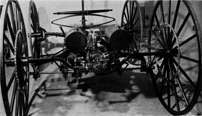
Figure 24.—Running gear of Duryea vehicle, showing the second engine and other parts as used in January 1894.
The same evening, the late edition ran a brief paragraph stating that "the test was made to determine the value of a leather friction surface for propelling the wagon, that had been substituted in place of the rubber surface, used in the former test." Bemis, according to Frank Duryea's recollection, was not impressed with the performance of the machine, saying "the thing is absolutely useless," and for a time it appeared that further support from Markham would not be forthcoming. Frank, believing eventual success to be near, drew up plans showing his geared transmission, and with these managed to gain Markham's partial support. Money for material and use of the shop was to continue, but Frank was to complete the work on his own time.
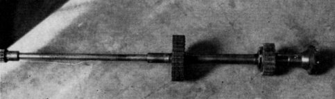
Figure 25.—Half of Jackshaft, showing rawhide gears, double shrouded pinion and half of the Columbia differential.
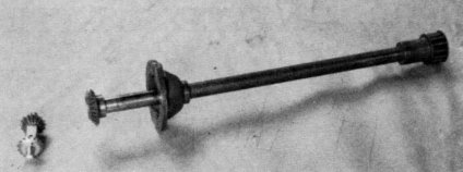
Figure 26.—Half of Jackshaft showing double-shrouded pinion and half of the Columbia differential.
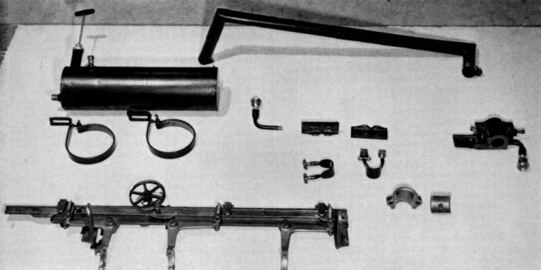
Figure 27.—Cam bar in foreground, operated by tiller, actuates the various clutches of the transmission. The overflow gasoline tank with the hand pump can be seen in the rear.
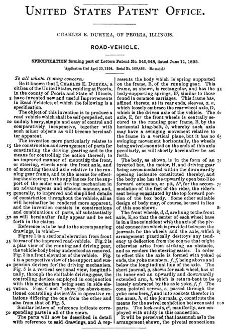
Text of Patent Letter
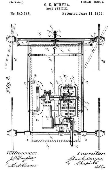
Figure 28.—A drawing and the first page of the specifications of the first patent issued to C. E. Duryea. It can be readily seen that this drawing was not made after the plan of the first vehicle. Larger size rotated image.
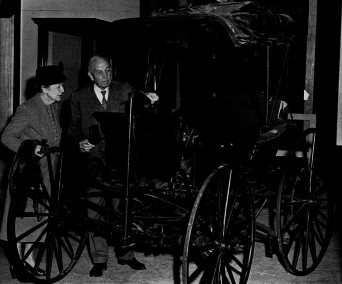
Figure 29.—Mr. and Mrs. Frank Duryea examining vehicle in the Smithsonian Institution before restoration.
Footnotes
Text of Letter (page 14)
24 Nov 1920
Dear Mr Mitman
On the train I had some time to puzzle over that car. Been working nights to make up time lost in the day so did not hav much.
I made a sketch for you but did not show the spring that holds the circuit breaker in contact with the spark point. That thin finger was part of it. A spring was wound spirally--not helically--around the projecting end of the breaker pivot and the end of the spring hookt over the thin finger. See sketch herwith.
Just how the central end of the spring wire was fastened to the square of the pivot I do not kno. We did in some cases bore a hole thru and simply stick the spring thru but this put most of the action right at the bend in the wire and it broke quickly. So in other cases we fitted a light grooved spool or pulley and wound the spring around this and so avoided a sharp bend. If this was used it has been lost with the spring. A couple generations of boys playing in that barn was too many.
The Haynes steering sketch also worries me. If that vertical post came up thru that slot in the floor the crank had to be long as the sketch shows in order to get over to the driver conveniently. Then if he tried to make a complete circle with it he could not reach far enuf forward to do it easily. And he had to make a turn or two be cause H shows bevel gears of about same size so the post had to make same number of turns the worm made. Sketch herewith to illustrate my thought.
Text of Article (page 20)
NO USE FOR HORSES.
Springfield Mechanics Devise a New Mode of Travel.
Ingenious Wagon Now Being Made in This City for Which the Makers Claim Great Things.
A new motor carriage, which, if the preliminary tests prove successful as is expected, will revolutionize the mode of travel on highways, and do away with the horse as a means of transportation, is being made in this city. It is quite probable that within a short time one may be able to see an ordinary carriage in almost every respect, running along the streets or climbing country hills without visible means of propulsion. The carriage is being built by J. F. Duryea, the designer and B. F. Markham, who have been at work on it for over a year. The vehicle was designed by C. E. Duryea, a bicycle manufacturer of Peoria, Ill., and he communicated his scheme to his brother, who is a practical machanic in this city.
The propelling power is furnished by a two-horse power gasoline motor situated near the rear axle and which, when started, runs continuously to the end of the trip, notwithstanding the number of times the carriage may be stopped. The speed of the motor is uniform, being about 500 revolutions a minute, and is so arranged that it gives a multiplied power for climbing hills and the lower the rate of speed the greater power is furnished by the motor. The slowest that the carriage can be driven is three miles an hour and the speed can be increased to fourteen or fifteen miles an hour. The power is transferred from the driving wheel of the motor, which runs horizontally with the main shaft by an endless friction belt running on a drum wheel. The belt is controlled by a lever within easy reach of the driver and is shifted along the drum wheel to increase or decrease the speed. The driving wheel is about twenty inches in diameter, having in its center a depression to which the belt is shifted to stop the carriage.
The carriage can be reversed by shifting the belt from the end of the drum, which gives the forward motion to the opposite side beyond the depression in the driving wheel. The power which has been transferred to the driving shaft from the motor is in turn transferred to the two rear wheels of the carriage by a combination gear and sprockets. An endless chain connects the sprockets on the carriage wheels to the sprocket wheels on the driving shaft. All of the motive power is located under the body of an ordinary phaeton, the hight of which is not increased by the machinery. The motor is started by a crank which is easily applied to a shaft in the rear of the carriage and the gasoline is ignited in the cylinder by electricity. An automatic device stops the flow of gasoline into the cylinder when the motor ceases running. The gasoline is carried in tanks, which hold about two gallons, and which will run the carriage for about eight hours. The wagon is guided by a bicycle bar, and the speed is also controlled by this bar.
The method employed in this is as follows: To start the carriage press the lever down; to reverse it throw the lever up and to guide the wagon turn the lever either to the right or left. The front axle instead of turning horizontally plays up and down, in order that the machinery may be on a level with the rear wheels, while the front wheels are set on the axle by a pivotal joint and are connected with the guiding lever by bars with ball bearings. The carriage complete weighs about 220 pounds, and the essential features are already covered by patents while others are pending.
It is estimated that the carriages can be sold for about $400, and a stock company will probably be formed to manufacture them.
Text of Patent Letter (page 24)
United States Patent Office.
CHARLES E. DURYEA, OF PEORIA, ILLINOIS.
ROAD-VEHICLE.
SPECIFICATION forming part of Letters Patent No. 540,648, dated June 11, 1895.
Application filed April 30, 1894. Serial No. 509,466. (No model.)
To all whom it may concern:
Be it known that I, Charles E. Duryea, a citizen of the United States, residing at Peoria, in the county of Peoria and State of Illinois, have invented new and useful Improvements in Road-Vehicles, of which the following is a specification.
The object of this invention is to produce a road vehicle which shall be self-propelled, not unduly heavy, simple and easy of control and comparatively inexpensive, together with such minor objects as will become hereinafter apparent.
The invention more particularly relates to the construction and arrangement of parts for constituting the driving gearing and to the means for controlling the action thereof; to an improved manner of mounting the front, or steering, wheels upon the front axle, and of mounting the said axle relative to the running gear frame, and to the means for effecting the steering; to the appliances for the support of the motor and driving mechanism in an advantageous and efficient manner, and, generally, to improved and simplified details of construction throughout the vehicle, all as will hereinafter be rendered more apparent, and the invention consists in constructions and combinations of parts, all substantially as will hereinafter fully appear and be set forth in the claims.
Reference is to be had to the accompanying drawings, in which—
Figure 1 is a sectional elevation from front to rear of the improved road-vehicle. Fig. 2 is a plan view of the running and driving gear, the vehicle-body being understood as removed. Fig. 3 is a front elevation of the vehicle. Fig. 4 is a perspective view of the support and suspension devices for the driving mechanism. Fig. 5 is a vertical sectional view, longitudinally, through the shiftable driving-gear, the controlling devices employed in conjunction with this mechanism being seen in side elevation. Figs. 6 and 7 show the above-mentioned controlling devices as in operative relations differing the one from the other and also from that of Fig. 5.
Similar letters of reference indicate corresponding parts in all of the views.
The parts will now be described in detail with reference to said drawings, and A represents the body which is spring supported on the frame, B, of the running gear. This frame, as shown, is rectangular, and has the body-supporting springs, B2, similar to those found in common carriages. This frame has, affixed thereto, at its rear ends, sleeves, a, a, which loosely embrace the rear wheel axle, D, which is the driven axle of the vehicle. The axle, E, for the front wheels is centrally secured to the running gear frame, B, by the horizontal king-bolt, b, whereby such axle may have a swinging movement relative to the frame in a vertical plane, but it has no swinging movement horizontally, the wheels being swivel-mounted on the ends of this axle peculiarly, as will shortly hereinafter be set forth.
The body, as shown, is in the form of an inverted box, the motor, H, and driving gear being accommodated within the downwardly opening inclosure constituted thereby, and the body also has the upwardly open box-like forward extension, or pit, A2, for the accommodation of the feet of the rider, the rider's seat being constituted by the top forward portion of the box body. Some other suitable design of body may, of course, be used in lieu of this one shown.
The front wheels, d, d, are hung to the front axle, E, so that the center of each wheel base is in a line coincident with the axis of the pivotal connection which is provided between the journals for the wheels and the axle, which arrangement practically destroys any tendency to deflection from the course that might otherwise arise from striking an obstacle, and so renders the steering easier. In order to effect this the axle is formed with yoked ends, the yoke members, f, f, being above and below the longitudinal line of the axle. The short journal, g, shown for each wheel, has at its inner end an upwardly and downwardly extended arm, h, which is return-bent to be loosely embraced by the axle yoke, f, f. The cone pointed screws, c, passed through the yoke members, f, and into sockets therefor in the arms, h, of the journals, g, constitute the means for the swivel connection between said parts. The lock-nuts, c2, manifestly, are employed with utility in this connection.
It will be perceived that inasmuch as in the arrangement shown, the pivotal connections
Paper 34 - Transcriber's Note
Letters printed upside down have been corrected. The transcriptions retain all typographical and gramatical errors.
Contributions from The Museum of History and Technology: Paper 35 The Borghesi Astronomical Clock In the Museum of History and Technology
Silvio A. Bedini
DEVELOPMENT OF ASTRONOMICAL CLOCKS 32
DESIGNER BORGHESI 33
CLOCKMAKER BERTOLLA 34
FIRST BORGHESI CLOCK 38
SECOND BORGHESI CLOCK 41
BORGHESIAN THEORY OF THE UNIVERSE 54
LAST YEARS 57
THE CLOCKS OF BARTOLOMEO ANTONIO BERTOLLA 59
APPENDIX 71
BIBLIOGRAPHY 76
INDEX
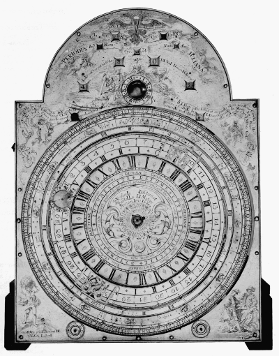
Figure 1.—The dial plate of the Borghesi clock, showing the horary and astronomical indications which are automatically presented.
Silvio A. Bedini
The Borghesi Astronomical Clock In the Museum of History and Technology
The history of the 18th-century Borghesi astronomical clock is described here from contemporary source material. The evolution of its design by Father Francesco Borghesi and the building of the complex mechanism devised by the clockmaker, Bartolomeo Antonio Bertolla, is a story of the vision of one man turned into reality by another. The result of their collaboration is the unique, astronomical timepiece now in the Museum of History and Technology.
The Author: Silvio A. Bedini is curator of mechanical and civil engineering in the Smithsonian Institution's Museum of History and Technology.
“… All this work I had performed eagerly, so that, while in my room, I might contemplate leisurely, both during the day and in the night, the true face of the heavens and of the seas unobscured by clouds, even though I had no astronomical equipment.” [1]
With these words, Father Francesco Borghesi (1723-1802) of Mechel described the reasons which inspired him to invent a unique astronomical clock which is now in the horological collection of the Museum of History and Technology.
This complicated mechanism, which performs a multitude of functions, was designed by Father Francesco Borghesi, a secular priest in Venezia Tridentina. It was constructed in 1764 under his direction by a provincial clockmaker named Bartolomeo Antonio Bertolla (1702-1789) of Mocenigo di Rumo. It was the second of two complicated astronomical clocks which Father Borghesi designed and which Bertolla constructed. According to contemporary sources, this clock was presented to the Empress Maria Theresa of Austria soon after its completion.
Its history is rather hazy, except for the fact that in 1780 this second Borghesi timepiece was still in the Imperial Palace in Vienna. The clock was again noted in 1927 when it was sold at a public auction in New York. [2] Subsequently, it was acquired for the Smithsonian Institution.
ACKNOWLEDGMENTS
The author wishes to acknowledge the valuable assistance received from the following: Dr. Amos Avery, Amherst, Massachusetts; Mr. Edwin A. Battison, curator of light machinery and horology, U.S. National Museum; Dott. Richard Blaas, Oesterreiches Staatsarchiv, Vienna; Dott. Adolfo Cetto, librarian, Biblioteca Comunale di Trento, who made copies of Borghesi's two volumes available; Signor Mario di Mario, editor of La Clessidra, Rome, who permitted several of the illustrations in Sig. Luigi Pippa's article to be used herein; Mr. Walter A. Gilbert, Norwich, Connecticut; Dr. Heinrich Linardi, Uhrenmuseum der Stadt Wien, Vienna; Signor Luigi Pippa, Milan, Italy; Cav. Ing. Guido Ucelli di Nemi, Presidente, and Dott. Federico Morelli and Cav. Orazio Curti of the Museo Nazionale della Scienza e della Tecnica, Milan, for their cooperation on the descriptions and illustrations of the restored clockshop of Bartolomeo Antonio Bertolla; and Dr. Edward Waters, Division of Music, Library of Congress, Washington, D.C.
The translation from Francesco Borghesi's Latin texts, which made this study possible, were made by: Rev. Neil Herlihy, S.J., Rev. Francis J. Heyden, S.J., and Rev. Stephen X. Winters, S.J., Georgetown University, Washington, D.C.; and Rev. Daniel Hunter, O.P., and Rev. Robert Stenger, O.P., Dominican House of Studies, Washington, D.C.
Development of Astronomical Clocks
The history of the great theoretical and mechanical achievement which the Borghesi clock represents has been most adequately covered elsewhere.[3] Consideration of the development of equation and astronomical clocks is required here only for the purpose of relating the Borghesi timepiece with the other significant developments in this branch of horology.
The invention of the anchor escapement in about 1670, and the consequent greater accuracy in time-telling, led to increased preoccupation with precision. Daily differences in time as recorded by sundials and clocks became more noticeable. Finally, in the second half of the 17th century, some attempt was made to construct mechanical clocks combined with sundials as well as astronomical clocks.
With the improvement of precision time-telling, it became necessary to reconcile the actual difference between true and mean time. Although a great variety of time-equation tables were produced, there was a considerable margin for error in their use. This led to the construction of mechanical clocks in which the equation of time was automatically accomplished. A few were produced late in the 17th and early 18th century at considerable cost and, consequently, with little popularity. Equation sundials were also developed which were elaborately ingenious, but they were not completely practical. Inevitably, they were supplanted by the mechanical equation clock.
Probably the first documented mention of an equation clock is in the diary of John Evelyn who recorded that in 1666 he visited the Royal Society where he witnessed a curious clock, which showed the equation of time, being presented by a certain Mercator. More data on the subject appeared in the first two decades of the 18th century, when Henry Sully, Joseph Williamson, Daniel Quare, and Thomas Tompion—who were among the foremost English clockmakers of all time—produced elaborate examples of these timepieces. Another significant maker was Dowe Williamson, who became Court Clockmaker to Emperor Charles VI of Austria. In London, Joseph Williamson produced some of the finest astronomical timepieces of this type that have been known. The interest in the subject next shifted to France where many fine examples were produced during the first half of the 18th century.
Just after the middle of the 18th century, the subject of astronomical clocks suddenly became a major horological preoccupation in another region, namely, Austria, where the work in this field was apparently done exclusively by members of the clergy. The earliest was Father Philipp Matthäus Hahn (1739-1790) of Württemberg. [4] Father Hahn considered the equation of time as only one part of a plan to represent astronomical occurrences by means of clockwork. In addition to planetaria and similar mechanisms, Father Hahn produced two extraordinary astronomical, tall-case clocks, both of which survive in public museums.
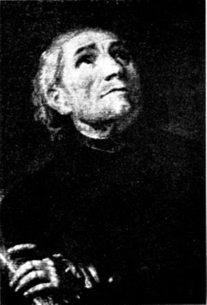
Figure 2.—Portrait of Father Francesco Borghesi, inventor and designer of the astronomical clock in the Museum of History and Technology.
Another of the clerical clockmakers was Father Aurelianus à San Daniele (1728-1782), an Augustine monk in the monastery of the Imperial Court at Vienna.[5] His four complicated astronomical clocks, which exist in museums at present, are comparable to those produced by Father Hahn. The third cleric was Brother David à San Cajetano (1736-1796) in the same Augustine order to which Father Aurelianus belonged. He achieved note as the author of various publications, including Neue Rädergebäude [6] [New Construction of Wheels] relating to planet-wheels, or gear-trains containing epicyclic elements. He constructed a clock based on an elaborate astronomical design which was substantially different from the others. The fourth of the ecclesiasts who designed astronomical clocks in this period was Father Klein of Prague, who produced a complicated astronomical timepiece in about 1738.
The fact that such important and outstanding examples of astronomical clocks were produced exclusively by ecclesiasts in Austria during the second half of the 18th century is especially significant. It is particularly so when a fifth cleric is added to the group, also an Austrian subject although Italian by heritage, in the person of Father Francesco Borghesi.
Although only Father Borghesi's second astronomical clock is now known, it is apparent that this example in the Museum of History and Technology represents an experiment in astronomical time-telling comparable to any of the timepieces produced by Father Hahn, Father Aurelianus, Brother David à San Cajetano or Father Klein.
This combination of five clerical clockmakers who lived in the same region during the same period of time is sufficiently unusual. However, the fact that each of them apparently worked without association with any of the others leads to the conjecture that a common factor must have led them to their individual preoccupation with astronomical horology. What the link may have been is not apparent from the surviving records of the lives and works of these clerics. Certainly it was not an interest in astronomy or clockmaking per se, because other than the astronomical clocks, none of these horological inventors—with the possible exception of Father Hahn—worked in any other aspect of the fields of astronomy or horology. However, after a comprehensive study of Father Borghesi's writings, there is little doubt of the religious basis of his own inspiration.
Designer Borghesi
Father Borghesi's story takes place in the picturesque mountainous region of what was then known as Venezia Tridentina (since 1947, Trentino-Alto Adige) in northern Italy, along the Tyrolean border of Austria. Because of its strategic position as the passage between Innsbruck and Verona, the possession of the Tridentina was contested again and again in the European wars, but during Father Borghesi's lifetime, the Tridentina was under Austrian domination.
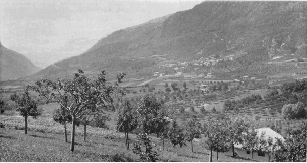
Figure 3.—Panorama of the village of Mechel in the valley of the Non, birthplace of Father Borghesi.
Deep within this mountainous district is the romantic valley of the Non, or Anáuni, with its great forests and ancient castles. Most maps do not mark it, and the tourist guides ignore it. [7] One of the chief communities is Cles, with its historic Renaissance buildings. The major city of the region is Trent on the Adige River, with its surviving Roman relics and Romanesque and Renaissance architecture.
The little villages scattered throughout the valley of the Non played no part in history, but such names as Mechel and Mocenigo di Rumo reflect the interchange of sovereignty. It was in the little village of Mechel that Francesco Borghesi was born in 1723. [8] Local records are meager and inadequate, and many of the details of Borghesi's life must be assumed. Inasmuch as the village was in a rural, agricultural district, Borghesi may have come from a family of farmers, vintners, or village tradesmen. Borghesi sought an education by entering the priesthood and was ordained a secular priest in Salzburg. He was first assigned as curate to the village parish of Rumo in the valley of the Non, a short distance from his birthplace. [9] Later, he was transferred to his native Mechel. He was inherently a man of simple tastes and of great piety. He tended to the needs of his mountain villagers and attended the births, weddings and deaths of his parishioners. It was during his assignment in this tiny community that Father Borghesi met and became friendly with the clockmaker, Bartolomeo Antonio Bertolla of nearby Mocenigo di Rumo.
Clockmaker Bertolla
Bartolomeo Antonio Bertolla was born in Mocenigo di Rumo, a short distance from Mechel, in 1702. [10] Nothing is known of his boyhood, other than the fact that he was mechanically inclined. At the age of 17 he was apprenticed to become a clockmaker with the master, Johann Georg Butzjäger of Neulengbach, a small village on the edge of the great Vienna woods. [11] This region was then part of the domain of the Archduke of Austria, of which Sankt Pölten was the capital.
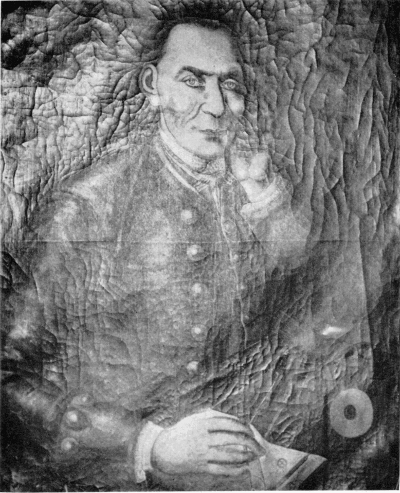
Figure 4.—Portrait of Bartolomeo Antonio Bertolla, clockmaker, of Mocenigo di Rumo. The canvas in oils is owned by descendants. In the upper left-hand corner is an inscription, now hardly legible, indicating that the portrait may have been painted after Bertolla's death on January 15, 1789. Translated, it states: "Bartolomeo Antonio Bertola [sic] Celebrated Mechanician and Inventor of various Instruments. Repairer of the clocks of Venice, Verona, Trent, and other localities. Maker of the Work which combines the Copernican and Ptolemaic Systems devised by Father Francesco Borghesi of Mechel, Laureate Mathematician, and humbly offered to Her Imperial Majesty Maria Theresa. Died in piety in his home at Rumo on 15 January 1789 at the age of 86." (Courtesy of Sig. Luigi Pippa of Milan.)
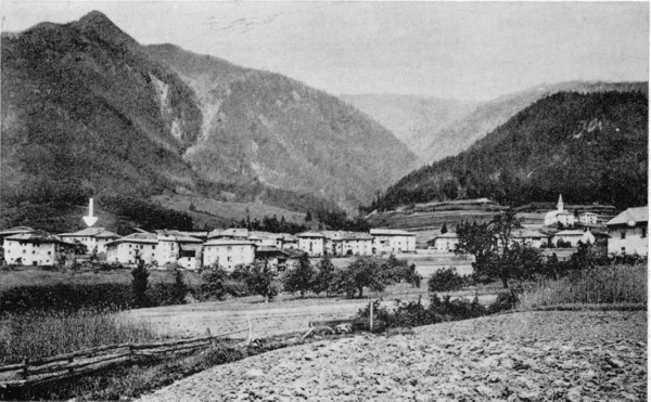
Figure 5.—The village of Mocenigo di Rumo in the valley of the Non. Arrow points to Bertolla's home and workshop at far left.
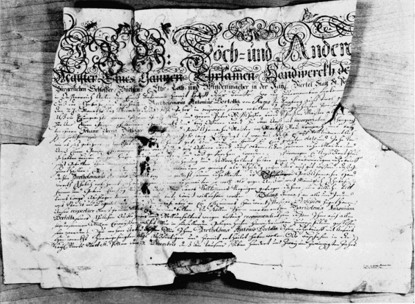
Figure 6.—Certificate of apprenticeship awarded to Bartolomeo Antonio Bertolla upon completion of his 3-year apprenticeship at Neulengbach, dated December 27, 1722.
Bertolla began his apprenticeship with Butzjäger under the auspices of the Corporation of Blacksmiths of Sankt Pölten in 1719. His training was supervised by two master locksmiths, Johann Christian Winz and Peter Wisshofer, who were members of the Corporation, and were assigned to serve as patrons for the apprentice. It was their obligation to make certain that he received good care and adequate instruction from his master. While he worked in Butzjäger's shop, Bertolla lived with the master's family in their home.
Bertolla's 3 years at Neulengbach passed quickly as he sought to absorb all that his master could teach him. Butzjäger was considered to be a good craftsman in the region, yet today there is not even a mention of his name in the lists of clockmakers. He specialized in the production and repair of "great clocks" which included tall-case, domestic timepieces, and tower clocks. Butzjäger treated his apprentice well, and in return Bertolla rewarded him by being diligent and honest. His subsequent work is sufficient indication that he developed into an extremely skilled craftsman, and he became the equal of any clockmaker of his time.
The 3 years of apprenticeship were completed and on December 27, 1722, Bertolla received a certificate from the Corporation of Blacksmiths which assured whomever it might concern of Bertolla's skill, diligence and honesty, and permitted him to open his own shop as a clockmaker under the auspices of the Corporation. This document, which has been preserved by Bertolla's descendants, is an interesting record of the organization of the trade guilds in the 18th century, and, for that reason, has been translated from the original German:
We, the Superiors and other masters of the honorable corporation of municipal blacksmiths, armorers, and of smiths, in the Imperial City of St. Pölten in Austria by the river Enns, Declare by these Presents put in force by this document to anyone who waits to hear…. That the honorable and able Bartolomeo Antonio Bertolla of Rumo in Lentzberg, the Tyrol, on the 27th day of the month of December of the year 1719 was consigned as apprentice for three years, in the presence of two sponsoring masters for the purpose, the honorable Johann Christian Winz and Peter Wisshofer, both of them master locksmiths representing the entire honorable Corporation and others of open shop—to the honorable Johann Georg Butzjäger, incorporated with us, citizen and master clockmaker for large clocks in the merchant-village of Neulengbach in Wienerwald, as his master of the art, would have therefore perfectly and rightfully worked and learned, and
that afterwards, on the day and year noted at the bottom, he will be newly declared free and independent before us, representative of an entire and honorable Corporation and with open shop, of his above-mentioned master and of the two sponsoring masters mentioned,
and since he eagerly requested a truthful certificate of apprenticeship for his honest service as an apprentice and for his good behavior, and we having great pleasure as well as the duty of favoring the truth and well knowing that the aforesaid Bartolomeo Antonio Bertolla has learned honestly the art of clockmaking for great clocks from his aforesaid master, and that he has always behaved with honesty, obedience, faithfulness and diligence both towards his master and towards us to our complete satisfaction and, therefore, we cannot in any manner refuse his request, rather we wish to grant it with a clear conscience.
We Therefore Address to Everyone and to anyone in whatever state and rank, but particularly to those interested in our branch of this art, our respectful and courteous entreaty and request to consider Bartolomeo Antonio Bertolla well recommended for his honest apprenticeship and his good behavior, and to desire to favor him in every way, in such a manner that will assure our gratitude whenever an occasion presents itself.
For this purpose, we issue, as we have declared we wish to issue to you, Bartolomeo Antonio Bertolla, this certificate of apprenticeship, attaching to it the seal of our Corporation.
Executed in the city of St. Pölten on 27 December 1722. [12]
His apprenticeship over, Bertolla returned to his native region where he soon established a reputation for himself as one of the most skillful clockmakers in the Tridentina and produced timepieces of fine quality in some quantity. No records have survived concerning his personal life, but it is believed that he married probably soon after his return. He had no children of his own. To expand his business, he eventually took into his shop two nephews, the sons of a brother and a sister, as apprentices.
Bertolla's work brought him a sufficient number of clients, and he produced elaborate clocks for his more wealthy patrons.
In 1752, it is recorded that he repaired the great clock in the campanile of the Church of the Assumption of the Virgin Mary in Cles, the regional capital of the valley of the Non. The clock dated probably from the 16th century, and it seems likely that Bertolla replaced the original two-wheel train with a three-wheel movement, and that he added the present anchor escapement. [13]
It is not possible to determine when Father Borghesi first made Bertolla's acquaintance, but it may be assumed that they had become friends in the late 1750's.
After he had come to know Bertolla, Father Borghesi apparently spent many hours in the clockmaker's shop. He was fascinated by mechanics in any form, and the complications of clockwork particularly intrigued him. Bertolla was patient with the young priest, explaining the tools he had and their uses, the clocks he produced or repaired, and the principles which were involved. Father Borghesi listened willingly and as his understanding of timepieces grew, his curiosity increased.
In spite of himself, the priest could not be satisfied with the ordinary aspects of his friend's work and wanted to learn more. From a casual pastime, the study of time became an obsession with him. There was but one recourse: he went back to studying once again. This time it was not theology, however, but the sciences. Every moment he could spare went into the perusal of books on mathematics, astronomy, and associated subjects. He progressed rapidly, driven by his overpowering interest and aided by his quick intellect.
Little by little, Borghesi managed to acquire the basic texts that explained this new world to him, probably borrowing them from old seminary friends. As each new book came into his hands, he devoured it in his desire to master its contents. He discussed each new principle or precept that he learned with Bertolla. Together, they attempted to apply his new learning to the calculations necessary for a timepiece which would demonstrate the astronomical theories in visual form. Borghesi taught himself slowly, step by step, and the result was a profound understanding of astronomical science. He conceived the project of constructing a great astronomical clock which he felt could be accomplished by combining Bertolla's mechanical skills with his own recent mastery of astronomy and mathematics.
First Borghesi Clock
It is not difficult to visualize the two men, the priest and the clockmaker, as they sat together night after night working out their plans. Father Borghesi would painstakingly outline the astronomical principles he wished to have the clock exhibit and the mathematical principles which would be involved to operate them. Bertolla concentrated on them and tried to transcribe the principles into functional mechanical terms, visualizing each operation in terms of wheels and gears. Little by little the two men coordinated the numerous elements and welded them into an operating entity. They adjourned either to the stark simplicity of the rectory or, probably more often, to Bertolla's little home workshop, the priest standing over his friend while the latter worked at his bench in the dark paneled interior illuminated only by the several lamps on the work benches.
This first clock which the two men combined to create is a monument to the great scientific knowledge of the self-taught priest and the technical ability of the clockmaker—a unity combining astronomical science, mechanics, and artistry. The story of the project is told in a little book, Novissima Ac Perpetua Astronomica…, which Borghesi later published. Explaining the incentive which inspired him, and the premises from which he began his work, he wrote:
From the foundation of astronomical science long ago, innumerable [and] repeated observations of both ancient and modern astronomers, emerged at last from their hiding places. Made light of by the jests of so many outstanding intellects, they have so successfully brought to light the paths of the stars and their motions, which are more complicated to us than the Gordian knots. Now it is possible for even an amateur in astronomy, sufficiently instructed, to predict for any given time not only the mean position of the planets, but also their true longitude and latitude, and even the true time of their conjunctions, and their ecliptic oppositions, with all the attendant circumstances. Yet, until now, no hypothesis has been devised which would force an automaton to show to us, before our very eyes, the eclipses of the planets in their true and certain times.
For though there have been men seeking with all their might to bind by laws their artificial heavens, by I know not how many and how great calculations, and to systematize the complexities of the rotations of celestial bodies; nevertheless, all of them, as if by common agreement, considered themselves to have made great contributions to mechanico-theoretical astronomy. However, they have only attained, even though closely, the mean locations of the secondary mobiles, and those by a certain rather crude calculation. Some attained by more, some by less, but all by some degree of wandering from the truth, either worn out by the intricacies of the motions, or deceived and deceiving by the errors of their calculations. This fact those well know, who, setting about to collect information of this kind, even those publicized not long ago, with true astronomical calculation, have been bored to death while digging out by the most elementary and superficial arithmetical torture, the worst of fallacies spontaneously erupting from thence.
It would seem that true calculations alone can be desired in mechanico-astronomics. Long study had not only convinced me that an automaton was within the realm of possibility, but that there were many mechanical systems by which it could be achieved. I girded myself for a new project and developed it theoretically from the ground up, but under such unhappy auspices that not only did all hope fail that anyone would ever appear who might have seemed willing to set his hand to the work, but that the new discovery itself was scoffed at by many as altogether a nightmarish delirium of an unbridled imagination.
The first months of the project must have seemed like an inspired dream to the two men, and then must have followed a period of hopeless depression. Bertolla undoubtedly felt many times that the clock was an aspiration far beyond their combined abilities and means, but the priest would not be thwarted in his ambition and refused to abandon the project. He felt that it was a work that they were destined to produce. Many times, he wrote, he chided and begged and shamed his erstwhile partner into resuming the project where it had been last abandoned. Little by little, the first clock began to take form. As each new difficulty was encountered, the two men would go back over the notes and sketches to trace the problem to its source. Often a new part of the mechanism would nullify another which had thus far operated successfully, and a complete rearrangement would be required.
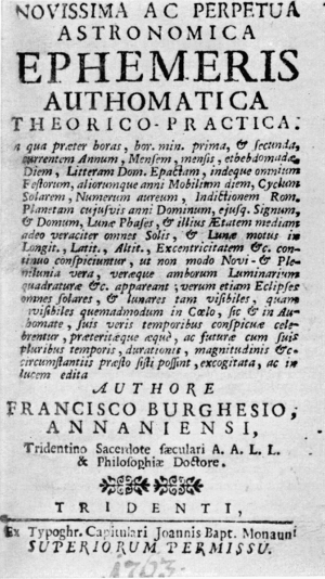
Figure 7.—Title Page of Father Borghesi's first book. The translation in its entirety is: "The Most Recent, Perpetual, Astronomical Calendar Clock: Theoretical—Practical: by means of which besides the hours, the minutes and seconds; the current year, the month; the day of the month and the day of the week; the dominical letter, epact, and thence, the day of all the feastdays, both fixed and movable; the solar cycle; the golden number; the Roman indiction; the dominant planet of any year and its sign; the phases of the moon and its mean age: and all the motions of the sun and the moon as to longitude, latitude, eccentricity, etc., are immediately seen, so accurately that [not only] the true new full moons and the true quadrature, etc., of the sun and moon appear, but also, all solar and lunar eclipses—both visible and invisible; as in heaven, so on the clock, they are conspicuously celebrated in their true times, and those of the past and those of the future, with their circumstances of time and duration, magnitude, etc., can be quickly determined. All this was devised and brought to light by the author, Francesco Borghesi of Anáuni, a secular priest of Trent, A.A.L.L. & Doctor of Philosophy. (Trent: From the printshop of Giovanni Battista Monauni, With Permission of Superiors.)" (Title page reproduced by permission of the Biblioteca della Citta di Trento.)
Again and again, Bertolla threw up his hands in despair and begged Father Borghesi to abandon the enterprise. He protested that he was not capable of producing such a complicated mechanism; he had neither the tools nor the skill. The priest wished to produce a clock such as the world had never seen before, such as the greatest scientists and clockmakers of all time had never been able to make. But Bertolla felt that he was only a provincial craftsman who could not hope to surpass them all with only his simple tools and training.
In his book on the first clock, Novissima Ac Perpetua Astronomica…, Father Borghesi wrote that when he had finally come within a few weeks of the embryo stage in the development of his clock, he was faced with the problem of bolstering the sagging enthusiasm of Bertolla. The clockmaker's original enthusiasm had shown promise of great results, but as the days passed and the problems of the multiplex and generally unfamiliar apparatus to be forged for the workings of the automaton became more complex, his ardor decreased. Finally, Bertolla became so discouraged by the scoffers and frustrated by the fact that the work was insufficiently organized that Father Borghesi wrote that "it almost became a harder task for me to bolster up by daily opportunity and importunity the failing patience of the artisan, frightened away from the work already begun, than it was for me to extract from the inner recesses of mathematics and astronomy, without light and without a guide, the whole fabric of the machine itself!"
In spite of Bertolla's protests, Father Borghesi prevailed, reviving his friend's interest once more until the two were deep in the project again. Months passed as they worked together on the mechanism and it seemed as if they lived for no other purpose. Inevitably, Bertolla's health began to suffer, undermined as it was by the constant nervous tension, and he eventually became ill from mental strain. He was forced to spend some time in bed, and for many weeks the subject of the clock was not discussed. Bertolla's other work, by which he made his living, suffered and it was several months before he was able to return to his little shop.
One year passed into another and the work progressed slowly. The first clock, which easily should have been finished in less than a year, was not completed until after three full years had passed. However, when the priest and the clockmaker put the finishing touches to their great clock, the result surpassed the greatest possible expectations, for it was truly a masterpiece. Not only did it illustrate the ecliptic phenomena of the moon, the sun and earth occurring in their proper time, as well as many other things, but it showed these operations as they succeeded in proper order, taking place through the centuries.
With mutual feelings of great pride, the two friends surveyed the result of their three years of endeavor. Bertolla realized that he had reached a point of maximum achievement in his work. He probably felt that now he could relax again, that his sleep would no longer be troubled by confused nightmares of wheels and gears that did not mesh together. Time was to prove otherwise.
PUBLISHED DESCRIPTION OF THE FIRST CLOCK
Father Borghesi soon came to the conclusion that it would be desirable to have a written description to explain the mechanism of the clock and its many indicators. He thereupon wrote out the story of how the clock was made, the reasons for embarking on the enterprise, the difficulties he had encountered, and the success which had crowned his and Bertolla's mutual labors. Finally, he described the operation of the clock's mechanism and the functions of its array of indicators.
The little book was written in Latin and only a few copies were printed, presumably at the priest's own expense, on a handpress by Giovanni Battista Monauni, printer to the Bishop in Trent. The little volume was stated by contemporary writers to have been published in 1763, although no date appears on the title page. The title translated is, in part, The Most Recent, Perpetual Astronomical Calendar Clock, Theoretical—Practical…. The work begins with an introduction for the reader in which Father Borghesi stated that:
… the little work, which, as far as I was concerned could easily have been finished in a year, was only completed after about three years. Fortunately, however, it was so far beyond the expectations of most, that not only am I able to foretell with certainty all the lunar ecliptic phenomena and the solar, or rather terrestrial, phenomena, carefully worked out in their true periods, among many other matters exhibited by the machine; but also, within a few hours, I can exhibit by altogether tangible evidence to the skeptics and the doubting those very same phenomena, occurring within the space of many years, or even centuries, and succeeding one another in proper order, with their many attendant circumstances. I was not much concerned about the other eclipses, such as those of Mercury, Venus, and the other stars wandering through the zodiac, or about the other solar eclipses from the transit of Mercury or Venus, since they are altogether undiscernible to the naked eye, and very few compilers of ephemerides wish them to be noted, probably for the same reason.
Do not, however, expect, star-loving reader, that here anything at all that you may wish can be drawn forth as from its source, for to demand this would be almost the same as to seek to drain as from a cup all the vast knowledge of the many arithmetical sciences from the narrow confines of one book. You will understand how impossible that is when, through prolonged labor, you have grown somewhat more mature in this kind of learning.
Wherefore, rather fully, and out of consideration for you, I have decided, setting aside these prolixities, with completely synoptic brevity and with all possible clarity to expound for you simply the proportion of the movements, the description of the machine, and its usage. As a result, when you have progressed a little in theoretical mechanics, you will not only be able to reduce all these things to their astronomical principles, but you may find the way more smoothly laid out for you even for perfecting the machine itself. And, thus, you may be more effectively encouraged to a successful conclusion. Let it be so now for you through the following 10 chapters!
After these rather hopeful assurances, Father Borghesi proceeded to provide a detailed description of the clock dial and functions in the 10 short chapters which he had promised, under a separate section entitled "Synopsis Totius Operis Mechanici," which is translated in its entirety in the appendix.
As Father Borghesi prepared his little volume about his first clock, and described its unusual features and outlined its functions, which were primarily to place in evidence the celestial constellations, it occurred to him that it would now be easier after the experience he had acquired with his first timepiece, to construct another clock, which would present the motions of the two astronomical systems, the Ptolemaic and the Copernican. In this first book, he promised the reader that he would undertake the second project. It is fortunate that Father Borghesi undertook this project for the second clock is the only example of his work that is known to exist today. Extensive research has not shown what happened to the first clock, although several sources state that both timepieces were presented to Empress Maria Theresa sometime between 1764 and 1780.
Second Borghesi Clock
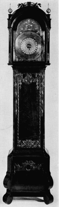
Figure 8.—The Borghesi clock in the Museum of History and Technology, constructed in 1764 by Bartolomeo Antonio Bertolla of Mocenigo di Rumo from the designs of Father Francesco Borghesi of Rumo and Mechel.
Father Borghesi lost no time in initiating the project of the second clock. The first and most important step was to inform Bertolla and enlist his assistance. Bertolla was adamant: he had had enough of complicated astronomical movements. He was delighted by the prospect of returning to his former simple life, producing simple, domestic, elementary movements for his country clients. Father Borghesi begged and cajoled. The second clock would be a much simpler one to construct, he persisted. After all, they had gained invaluable experience from the production of the first clock. Furthermore, he had already completed its design.
Bertolla apparently wavered in his resolve and, unwillingly and against his better judgment, he allowed the priest's inducements to prevail. Once again, the two friends yielded their leisure hours to a study of the priest's books and drawings as Father Borghesi enthusiastically elaborated his design for the timepiece, and Bertolla attempted to transcribe astronomical indications into terms of wheel counts. The second clock was, as Borghesi had promised, much easier of execution. Within a year, it was completed and functioned with complete success.
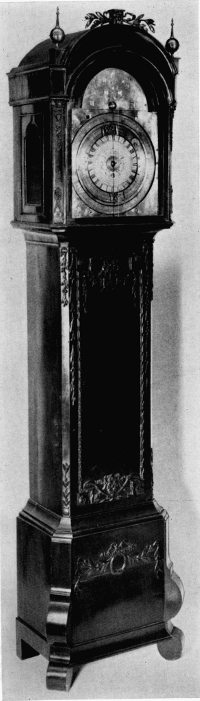
Figure 9.—Another view of the Borghesi clock.
This is the clock now in the Museum of History and Technology. It is housed in a tall case of dark-red mahogany veneered on oak, with restrained carving featuring ribands and foliate motifs. Gilt-brass decorations flank the face of the hood, which is surmounted by three gilt-brass finials in the form of orbs. A wide door in the waist may be opened to attend the weights. The case is 7 feet 8 inches high, 201/2 inches wide at the waist, and 14 inches in depth.
The dial is of gilt brass, measuring 21 inches high and 15 inches in width, with a number of supplementary silvered dials visible through its openings. Instead of hands, the dial utilizes three concentric rings moving around a central disc, the indications of which are read at two bisecting gilt lines inscribed in the glass face. Twelve separate functions are performed by the chapter ring assembly alone, and there are 14 openings on the dial. It is estimated that the clock performs 30 separate functions, including striking and chiming. Of the multiple chapter rings, the outermost is 11/8 inches wide, the center ring is 3/8 inch wide, and the innermost ring measures 11/4 inches in width.
THE DIAL-PLATE ENGRAVINGS
The gilt dial is incised throughout with figures and inscriptions in engraving of the very finest quality, as is evidenced in the illustrations. The frontispiece is surmounted at its center by the crowned double eagle of the House of Hapsburg, indicating the identity of the sovereign in whose reign it was made, Emperor Francis I or the Empress Maria Theresa of Austria. Below the eagle at either side are flying cherubs supporting ribands with inscriptions. Centered at the bottom of the frontispiece immediately above the chapter rings is the moving silvered orb representing the sun. Surrounding it is a tableau of the Holy Trinity, with the Virgin Mary being crowned by Christ holding a cross at the left and God with a sword in hand at the right, and a dove representing the Holy Spirit hovering over the Virgin's head. Father S. X. Winters, S.J., considers it reminiscent of the triptych "The Coronation of the Virgin" by Fra Lippo Lippi.
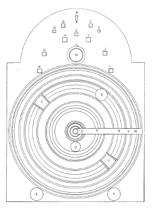
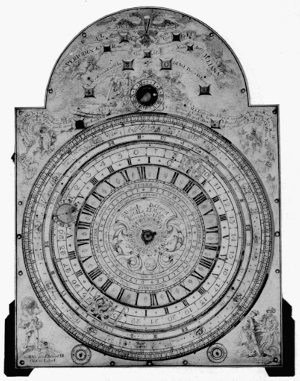
Figure 10.—Diagram of the dial plate. Figure 11.—Dial plate of the Borghesi clock.
KEY TO DIAGRAM OF THE DIAL PLATE
A Dominating planet, represented by its symbol and its house;
B Dominical letter (Lit. Dom.);
C Epacts (Cyc. EpEC);
D Roman indiction (Ind. Rom.), part of the reckoning of the Julian period;
E Solar cycle, (Cyc. Sol.), part of the reckoning for the Julian period;
F Golden number (Num. Aur.), part of the reckoning for the Julian period;
G, H, I, J The era, or the current year; part of the six windows of the Iris, or rainbow;
K Shuttered winding hole, for winding up the weights; part of the six windows of the Iris;
L The era, or the month of the current year; part of the Iris, or six windows of the rainbow;
M The sun in its epicycle;
N The 12 signs of the sun's anomaly;
O, P The first chapter ring representing the equatorial globe of the week, revolving from left to right;
Q The coming day indicated through the window;
R The second chapter ring; including the synodic-periodic measure of the tides, the days of the median lunar-synodic age, the signs and degrees of the signs for mean distance of the moon from the sun;
S Epicycle of the moon with signs of its anomaly;
T Head of the dragon (Cap. Draconis);
U Tail of the dragon (Cauda Draconis), for measuring eclipses of the earth and of the moon;
V Third chapter ring, with degrees of lunar latitude and some fixed stars;
W Fourth chapter ring, showing firmament of fixed stars, signs of the zodiac and degrees of the signs, the months of the year, and days of the months, revolving left to right for the course of a mean astronomical year;
X Adjustment marked Claudit (it closes) and Aperit (it opens) for disengaging dial work for the purpose of making astronomical experiments and computations;
Y Adjustment marked Concitat (it accelerates) and Retardit (it retards) for fast and slow adjustments of the movement.
In the upper spandrels of the dial are two more cherubs bearing ribands with inscriptions. In the lower left corner is a magnificent engraving of Atlas upholding the globe of the world, inscribed with the zodiac, over his head. The lower right corner features the figures of two noblemen apparently examining and discussing an orb upon a table, the significance of which is not clear.
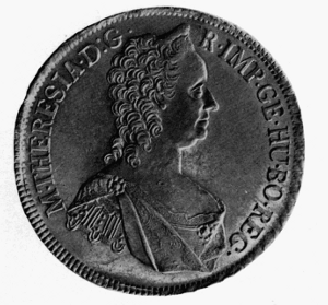
Figure 12.—Empress Maria Theresa, to whom Father Borghesi is stated to have presented his two astronomical clocks. The coin bearing her portrait is in the Museum of History and Technology.
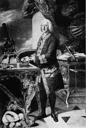
Figure 13.—Portrait of Francis I, Emperor of the Holy Roman Empire, to whom Father Borghesi's astronomical clock in the Museum of History and Technology appears to have been inscribed.
THE INSCRIPTIONS
Beginning with the uppermost part of the frontispiece, there are nine inscriptions in Latin on the dial plate. The topmost is Franciscvs I sit plan. Dominator aeternvs. The phrase has reference to Francis I, who was Emperor of the Holy Roman Empire, from 1745-1765, and husband of Empress Maria Theresa of Austria. The phrase may be translated as "May Francis I be the eternal ruler by favor of the planets" or more simply "Long Live Francis I, Emperor." [14] Although the dial plate of the Borghesi clock is inscribed with his name, the records indicate that the clock was presented to Maria Theresa. Francis I may have already died before the presentation was made.
From the left to right over the tableau of the Holy Trinity is the phrase "Lavs sacrosanctae Triadi Vni Deo, et Deiparae" (Praise [be] to the most Holy Trinity, to the one God, and to the Mother of God).
Within the upper left and right spandrels is inscribed:
Isthaec, Signum grande apparvit in Coelo * sancta Dei genitrix amicta sole * Illibato pede Lvnae et serpentis nigra premens Cornva * bis senis pvlcherrime Coronata syderibvs * Tempe indesinenter clavsa, scatvrigo signata * Cedrvs in Libano, Cypresvs in Monte Sion * Mater pvrae Dilectionis sanctaeqve spei * Chara patris aeterni proles, Verbi Mater, sponsaqve procedentis *, gratiae et gloriae circvmdata varietate.
This inscription is a eulogy to the Virgin Mary assembled from the texts of Holy Scripture. In addition, each lemma, contained within asterisks, carries out the chronogram 1764, the year the clock was completed. Each lemma is translated and identified from the Douay-Rheims version of the Bible:
This woman: a great sign appeared in Heaven (Apocalypse 12:1) * The Holy Mother of God clothed with the sun (Apocalypse 12:1) * And with unharmed foot crushing the black horns of the moon (Apocalypse 12:1) and the serpent (Genesis 3:15) * Most beautifully crowned with twice-six (Apocalypse 12:1) * A garden [Tempe [15]] enclosed, sealed with a fountain [spring of water] (Song of Songs 4:12) * Like a cedar in Lebanon, and a cypress tree on Mount Zion; (Ecclesiasticus 24:17) * Mother of pure love and of holy hope: Beloved daughter of the Eternal Father, Mother of the Word, Spouse of the Holy Spirit: (Ecclesiasticus 24:24) * Surrounded with a diversity of grace and glory (Psalms 44:10).
Figure 14.—The bottom right corner of the dial plate, showing two noblemen contemplating an orb, with the inscription "Diligit Avdaces Trepidos Fortvna Repellet." (Fortune favors the daring and rejects the timid.) Figure 15.—The bottom left corner of the dial plate, showing the engraving of Atlas, with the inscription "Assidvo proni donant di cvncta labori." (The favorable gods willingly grant all things to the assiduous laborer.)
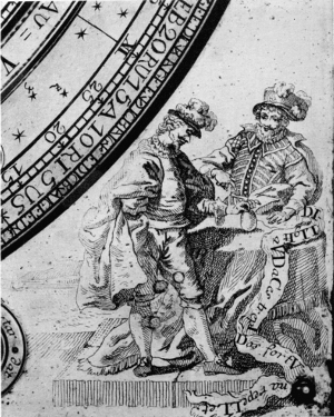
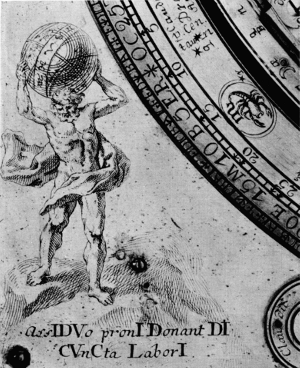
At the lower left corner below the figure of Atlas upholding the world is the phrase, Assidvo proni donant di cvncta labori. (The favorable gods willingly grant all things to the assiduous laborer.) The same phrase is quoted by Father Borghesi in the text of his second volume. The last inscription appears at the lower right corner under the figures of the two noblemen, Diligit avdaces trepidos fortvna repellet. (Fortune favors the daring and rejects the timid.) The last two inscriptions are in dactylic hexameter. They appear to be original compositions inasmuch as no classical prototypes have been identified.
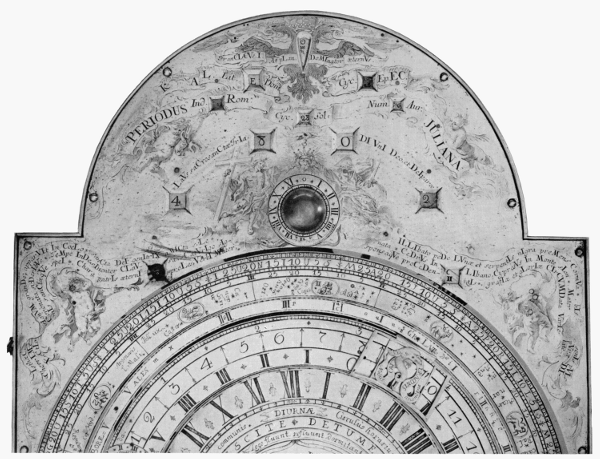
Figure 16.—Detail of frontispiece of the Borghesi clock, showing the apertures for calendar indicators and the details of the engraving.
CENTER DIAL INSCRIPTIONS
In addition to the inscriptions previously noted on the outer dial plate, there are three major inscriptions in the central dial. The outermost states Circulus horarius Soli, Lunae, Fixis, Nodis, Aestuique marino communis (the hour circle, common to the sun, the moon, the fixed stars, the nodes and to the sea tide). This inscription is divided into four parts by the insertion of four divisions for the day into canonical hours: [Horae] Nocturnae (night hours); Matutinae (morning hours); Diurnae (daytime hours) and Vespertinae (evening hours).
The next section of the central dial is inscribed Intumescite—Detumescite (rise and fall of the tides) repeated at intervals of approximately every six hours. Within the next section is the following inscription, inscribed continuously around the ring:
Lege fluunt, refluunt, dormitant hac maris undae: Ad Phoebi et Phoebes concordia iussa moventur Aequora; discordi iussu suspensa quiescunt.
Translated, this is:
By this law the sea waves ebb and flow and lie dormant: When Phoebus and Diana agree in their commands, the waters are moved; when they disagree, the waters lie silent. [16]
Within the central boss of the dial plate, the name of the maker is inscribed:
Bvrghesio Doctore, et Bertolla Limatore Annaniensibvs*
Translated, this is:
[By] Doctor Borghesi and Bertolla, mechanician citizens of Anáuni.
INDICATORS IN THE FRONTISPIECE
There are 12 windows in the frontispiece, through each of which appears an indication relating to time. Beginning at the top of the frontispiece of the dial, the first opening occurs on the breast of the imperial eagle. This indicates the dominating planet, represented by its symbol, and its house.
The opening in the eagle's left claw, labeled "Lit. Dom." is the dominical letter. The first seven days in the month of January are each assigned one of the letters a through g in order of appearance. The letter which coincides with the first Sunday within this period is called the dominical letter, and it serves for the following year. In leap year, two letters are required, one to February 29th and the letter next proceeding for the remainder of the year. This letter is used in connection with establishing the date of Easter Sunday. The date of Easter regulates the dates of the other movable feasts.
The eagle's right claw is labeled "Cyc. EpEC" and represents the epact, or the age of the moon on January 1st. It serves to find the moon's age by indicating the number of days to be added to each lunar year in order to complete a solar year. Twelve lunar months are nearly 11 days short of the solar year, so that the new moons in one year fall 11 days earlier than they did the preceding year. However, 30 days are deducted as an intercalary month since the moon has made a revolution in that time, and the remainder, 3, would be the epact.
Below the imperial eagle two winged cherubs support a riband with three indictions of the Julian period. This period of 7980 years is the product derived from multiplying together the sums of 28, which represents the cycle of the sun; 19, representing the cycle of the moon; and 15, which represents the Roman indiction. The Julian period is reckoned to have begun from 4713 B.C. so that the period will be completed in A.D. 3267. The first of the three openings is marked "Ind. Rom." or "Roman indiction," which was an edict by the Emperor Constantine in A.D. 312, providing for the assessment of a property tax at the beginning of each 15-year cycle. It continues to be used in ecclesiastical contracts. The second opening, which occurs immediately below the eagle, is marked "Cyc. Sol." (cycle of the sun). This cycle takes a period of 28 years, after which the days of the week once again fall upon the same days of the month as they did during the first year of the former cycle. There is no relationship with the course of the sun itself, but was invented for the purpose of determining the dominical letter which designates the days of the month on which the Sundays occur during each year of the cycle. Since cycles of the sun date from 9 years before the Christian era, it is necessary to add the digit 9 to the digits of the current year and then divide the result by 28. The quotient is the number of cycles which has passed, and the remainder will be the year of the cycle answering to the current year. The third opening on the riband is labeled "Num. Aur." (golden number). Meton, an astronomer of Athens, discovered in 432 B.C. that after a period of 19 years the new and the full moons returned on the same days of the month as they had before, and this is called the cycle of the moon. The Greeks were so impressed with this calculation that they had it inscribed in letters of gold upon stone, hence the golden number. The First Council of Nicaea in A.D. 325 determined that Meton's cycle was to be used to regulate the movable feasts of the Church.
Immediately above the chapter rings is an opening through which the orb of the sun is visible.
THE CHAPTER-RING ASSEMBLY
In a separate chapter in his second volume, entitled "Descriptio Authomatis Summa totius Operis Mechanici" (Description of the Automaton—Summary of the Complete Mechanism), Father Borghesi provided a description of the functions of the various indicators, prefixing it with the short poem shown in figure 18. He then continues:
In the middle of the frontispiece, as at the center of the universe, the terraqueous globe of the week revolves, with a daily motion turning from right to left, bringing with it from the round window the coming day and at the circumference the circle of hours common to the sun, to the moon, to the fixed stars, to the head and tail of the dragon, and to the raging sea.
The second circle revolves the synodic-periodic measure of the raging sea, the days of the median lunar-synodic age, the signs and individual degrees of the signs of the distance of the moon from the middle of the sun within the time of 29 terrestrial revolutions, hours 12.44.3.13. This circle revolves likewise from right to left around the center of the earth. In this second circle, another little orb revolves, bringing with it the epicycle of the moon, in which the little circle of the moon (whose illuminated middle always faces towards the sun), running from left to right through the signs of the anomaly; within 13 revolutions of the earth, hours 18.39.16. It descends from apogee to perigee and in just as many others it returns from perigee to apogee, to be carried down thus to true, back and front from the longitude and distance from the sun and from the middle of the earth.
The third circle (on which I have tried to indicate astronomically-geometrically in their places, the degrees of lunar latitude both in the south and in the north, and some fixed stars, those, namely, which can be separated by us from the moon which goes between) from left to right turns around the center of the earth, stretching out the head and tail of the dragon, on the inside above the second circle for noting and measuring the sun (but I should rather say the earth), and the eclipses of the moon, within 346 revolutions of the earth, hours 14.52.23.