Front matter (continued 8)
Reading edition
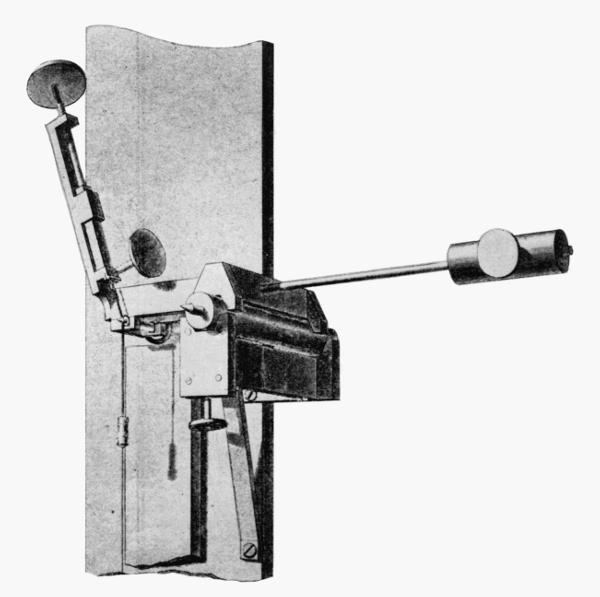
Figure 8.—Mode of suspension of Bessel’s pendulum is shown here. The iron wire is supported by the thumbscrew and clamp at the left, but passes over a pin at the center, which is actually the upper terminal of the pendulum. Bessel found this “cylinder of unrolling” superior to the clamps and knife edges of earlier pendulums. The counterweight at the right is part of a system for supporting the scale in such a way that it is not elongated by its own weight.
With this apparatus, Bessel determined the ratio of the lengths of the two pendulums and their times of vibration. From this the length of the seconds pendulum was calculated. His method eliminated the need to take into account such sources of inaccuracy as flexure of the pendulum wire and imperfections in the shape of the bob. (Portion of plate 7, Mémoires publiés par la Société française de Physique, vol. 4.)
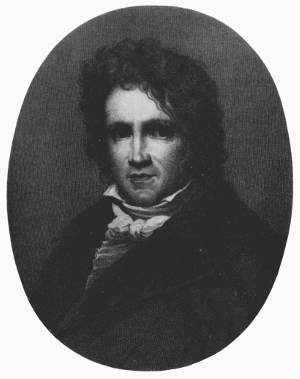
Figure 9.—Friedrich Wilhelm Bessel (1784-1846), German mathematician and astronomer. He became the first superintendent of the Prussian observatory established at Königsberg in 1810, and remained there during the remainder of his life. So important were his many contributions to precise measurement and calculation in astronomy that he is often considered the founder of the “modern” age in that science. This characteristic also shows in his venture into geodesy, 1826-1830, one product of which was the pendulum experiment reported in this article.
The latter effect had been discovered by Du Buat in 1786, [23] but his work was unknown to Bessel. The length of the seconds pendulum at Königsberg, reduced to sea level, was found by Bessel to be 440.8179 lines. In 1835, Bessel determined the intensity of gravity at a site in Berlin where observations later were conducted in the Imperial Office of Weights and Measures by Charles S. Peirce of the U.S. Coast Survey.
Kater’s Convertible and Invariable Pendulums
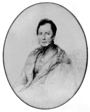
Figure 10.—Henry Kater (1777-1835), English army officer and physicist. His scientific career began during his military service in India, where he assisted in the “great trigonometrical survey.” Returned to England because of bad health, and retired in 1814, he pioneered (1818) in the development of the convertible pendulum as an alternative to the approximation of the “simple” pendulum for the measurement of the “seconds pendulum.” Kater’s convertible pendulum and the invariable pendulum introduced by him in 1819 were the basis of English pendulum work. (Photo courtesy National Portrait Gallery, London.)

Figure 11.—The attempt to approximate the simple (theoretical) pendulum in gravity experiments ended in 1817-18 when Henry Kater invented the compound convertible pendulum, from which the equivalent simple pendulum could be obtained according to the method of Huygens (see text, p. 314). Developed in connection with a project to fix the standard of English measure, Kater’s pendulum was called "compound" because it was a solid bar rather than the fine wire or string with which earlier experimenters had tried to approximate a "weightless" rod. It was called convertible because it is alternately swung from the two knife edges (a and b) at opposite ends. The weights (f and g) are adjusted so that the period of the pendulum is the same from either knife edge. The distance between the two knife edges is then equal to the length of the equivalent simple pendulum.
The systematic survey of the gravity field of the earth was given a great impetus by the contributions of Capt. Henry Kater, F.R.S. In 1817, he designed, constructed, and applied a convertible compound pendulum for the absolute determination of gravity at the house of Henry Browne, F.R.S., in Portland Place, London. [24] Kater’s convertible pendulum (fig. 11) consisted of a brass rod to which were attached a flat circular bob of brass and two adjustable weights, the smaller of which was adjusted by a screw. The convertibility of the pendulum was constituted by the provision of two knife edges turned inwards on opposite sides of the center of gravity. The pendulum was swung on each knife edge, and the adjustable weights were moved until the times of swing were the same about each knife edge. When the times were judged to be the same, the distance between the knife edges was inferred to be the length of the equivalent simple pendulum, in accordance with Huygens’ theorem on conjugate points of a compound pendulum. Kater determined the time of swing by the method of coincidences (fig. 12). He corrected for the buoyancy of the air. The final value of the length of the seconds pendulum at Browne’s house in London, reduced to sea level, was determined to be 39.13929 inches.
The convertible compound pendulum had been conceived prior to its realization by Kater. In 1792, on the occasion of the proposal in Paris to establish the standard of length as the length of the seconds pendulum, Baron de Prony had proposed the employment of a compound pendulum with three axes of oscillation. [25] In 1800, he proposed the convertible compound pendulum with knife edges about which the pendulum could complete swings in equal times. De Prony’s proposals were not accepted and his papers remained unpublished until 1889, at which time they were discovered by Defforges. The French decision was to experiment with the ball pendulum, and the determination of the length of the seconds pendulum was carried out by Borda and Cassini by methods previously described. Bohnenberger in his Astronomie (1811), [26] made the proposal to employ a convertible pendulum for the absolute determination of gravity; thus, he has received credit for priority in publication. Capt. Kater independently conceived of the convertible pendulum and was the first to design, construct, and swing one.
After his observations with the convertible pendulum, Capt. Kater designed an invariable compound pendulum with a single knife edge but otherwise similar in external form to the convertible pendulum [27] (fig. 13). Thirteen of these Kater invariable pendulums have been reported as constructed and swung at stations throughout the world. [28] Kater himself swung an invariable pendulum at a station in London and at various other stations in the British Isles. Capt. Edward Sabine, between 1820 and 1825, made voyages and swung Kater invariable pendulums at stations from the West Indies to Greenland and Spitzbergen. [29] In 1820, Kater swung a Kater invariable pendulum at London and then sent it to Goldingham, who swung it in 1821 at Madras, India. [30] Also in 1820, Kater supplied an invariable pendulum to Hall, who swung it at London and then made observations near the equator and in the Southern Hemisphere, and at London again in 1823. [31] The same pendulum, after its knives were reground, was delivered to Adm. Lütke of Russia, who observed gravity with it on a trip around the world between 1826 and 1829. [32]
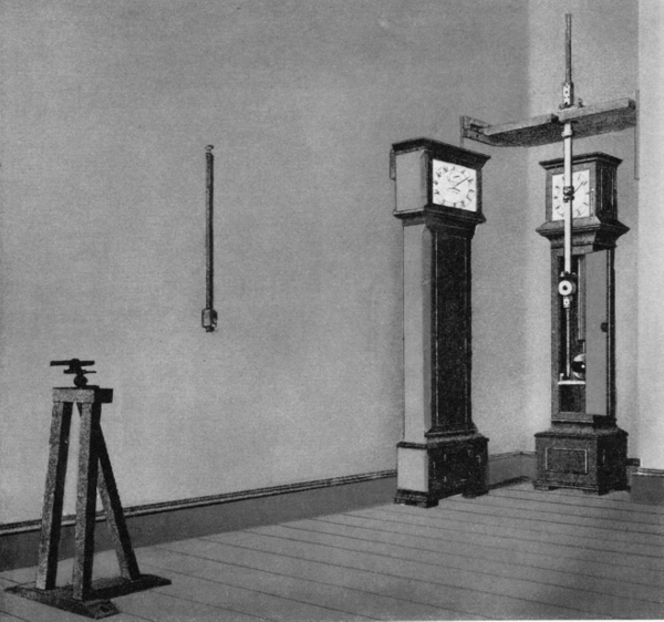
Figure 12.—The Kater convertible pendulum in use is placed before a clock, whose pendulum bob is directly behind the extended “tail” of the Kater pendulum. A white spot is painted on the center of the bob of the clock pendulum. The observing telescope, left, has a diaphragm with a vertical slit of such width that its view is just filled by the tail of the Kater pendulum when it is at rest. When the two pendulums are swinging, the white spot on the clock pendulum can be seen on each swing except that in which the two pendulums are in coincidence; thus, the coincidences are determined. (Portion of plate 5, Mémoires publiés par la Société française de Physique, vol. 4.)
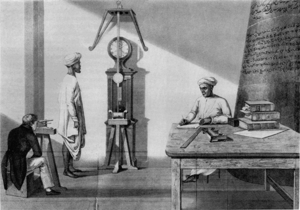
Figure 13.—This drawing accompanied John Goldingham’s report on the work done in India with Kater’s invariable pendulum. The value of gravity obtained, directly or indirectly, in terms of the simple pendulum, is called “absolute.” Once absolute values of gravity were established at a number of stations, it became possible to use the much simpler “relative” method for the measurement of gravity at new stations. Because it has only one knife edge, and does not involve the adjustments of the convertible pendulum, this one is called “invariable.” In use, it is first swung at a station where the absolute value of gravity has been established, and this period is then compared with its period at one or more new stations. Kater developed an invariable pendulum in 1819, which was used in England and in Madras, India, in 1821.
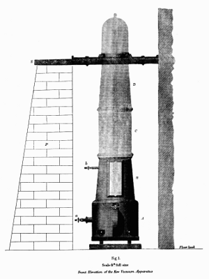
Figure 14.—Vacuum chamber for use with the Kater pendulum. Of a number of extraneous effects which tend to disturb the accuracy of pendulum observations the most important is air resistance. Experiments reported by the Greenwich (England) observatory in 1829 led to the development of a vacuum chamber within which the pendulum was swung.
While the British were engaged in swinging the Kater invariable pendulums to determine relative values of the length of the seconds pendulum, or of gravity, the French also sent out expeditions. Capt. de Freycinet made initial observations at Paris with three invariable brass pendulums and one wooden one, and then carried out observations at Rio de Janeiro, Cape of Good Hope, Île de France, Rawak (near New Guinea), Guam, Maui, and various other places. [33] A similar expedition was conducted in 1822-1825 by Captain Duperry. [34]
During the years from 1827 to 1840, various types of pendulum were constructed and swung by Francis Baily, a member of the Royal Astronomical Society, who reported in 1832 on experiments in which no less than 41 different pendulums were swung in vacuo, and their characteristics determined. [35] In 1836, Baily undertook to advise the American Lt. Charles Wilkes, who was to head the United States Exploring Expedition of 1838-1842, on the procurement of pendulums for this voyage. Wilkes ordered from the London instrument maker, Thomas Jones, two unusual pendulums, which Wilkes described as “those considered the best form by Mr. Baily for traveling pendulums,” and which Baily, himself, described as “precisely the same as the two invariable pendulums belonging to this [Royal Astronomical] Society,” except for the location of the knife edges.
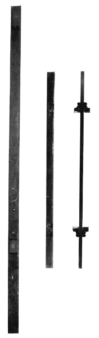
Figure 15.—One of Francis Baily’s pendulums (621/2 inches long), shown on the left, is now in the possession of the Science Museum, London, and, right, two views of a similar pendulum (375/8 inches long) made in the late 19th century by Edward Kübel, Washington, D.C., which is no. 316,876 in the collection of the U.S. National Museum. Among a large number of pendulums tried by Baily in London (1827-1840), was one which resembles the reversible pendulum superficially, but which is actually an invariable pendulum having knife edges at both ends. The purpose was apparently economy, since it is equivalent to two separate invariable pendulums. This is the type of pendulum used on the U.S. Exploring Expedition of 1838-1842. It is not known what use was made of the Kübel pendulum.
The unusual feature of these pendulums was in their symmetry of mass as well as of form. They were made of bars, of iron in one case, and of brass in the other, and each had two knife edges at opposite ends equidistant from the center. Thus, although they resembled reversible pendulums, their symmetry of mass prevented their use as such, and they were rather equivalent to four separate invariable pendulums. [36]
Wilkes was taught the use of the pendulum by Baily, and conducted experiments at Baily’s house, where the latter had carried out the work reported on in 1832. The subsequent experiments made on the U.S. Exploring Expedition were under the charge of Wilkes, himself, who made observations on 11 separate occasions, beginning with that in London (1836) and followed by others in New York, Washington, D.C., Rio de Janeiro, Sydney, Honolulu, “Pendulum Peak” (Mauna Loa), Mount Kanoha, Nesqually (Oregon Territory), and, finally, two more times in Washington, D.C. (1841 and 1845).
Wilkes’ results were communicated to Baily, who appears to have found the work defective because of insufficient attention to the maintenance of temperature constancy and to certain alterations made to the pendulums. [37] The results were also to have been included in the publications of the Expedition, but were part of the unpublished 24th volume. Fortunately they still exist, in what appears to be a printer’s proof. [38]
The Kater invariable pendulums were used to investigate the internal constitution of the earth. Airy sought to determine the density of the earth by observing the times of swing of pendulums at the top and bottom of a mine. The first experiments were made in 1826 at the Dolcoath copper mine in Cornwall, and failed when the pendulum fell to the bottom. In 1854, the experiments were again undertaken in the Harton coalpit, near Sunderland. [39] Gravity at the surface was greater than below, because of the attraction of a shell equal to the depth of the pit. From the density of the shell as determined from specimens of rock, Airy found the density of the earth to be 61/2 times greater than that of water. T. C. Mendenhall, in 1880, used a Kater convertible pendulum in an invariable manner to compare values of gravity on Fujiyama and at Tokyo, Japan. [40] He used a “simple” pendulum of the Borda type to determine the absolute value of gravity at Tokyo. From the values of gravity on the mountain and at Tokyo, and an estimate of the volume of the mountain, he estimated the mean density of the earth as 5.77 times greater than that of water.
In 1879, Maj. J. Herschel, R.E., stated:
The years from 1840 to 1865 are a complete blank, if we except Airy’s relative density experiments in 1854. This pause was broken simultaneously in three different ways. Two pendulums of the Kater pattern were sent to India; two after Bessel’s design were set to work in Russia; and at Geneva, Plantamour’s zealous experiments with a pendulum of the same kind mark the commencement of an era of renewed activity on the European continent. [41]
With the statement that Kater invariable pendulums nos. 4 and 6 (1821) were used in India between 1865 and 1873, we now consider the other events mentioned by Herschel.
Repsold-Bessel Reversible Pendulum
As we have noted, Bessel made determinations of gravity with a ball (“simple”) pendulum in the period 1825-1827 and in 1835 at Königsberg and Berlin, respectively. In the memoir on his observations at Königsberg, he set forth the theory of the symmetrical compound pendulum with interchangeable knife edges. [42] Bessel demonstrated theoretically that if the pendulum were symmetrical with respect to its geometrical center, if the times of swing about each axis were the same, the effects of buoyancy and of air set in motion would be eliminated. Laplace had already shown that the knife edge must be regarded as a cylinder and not as a mere line of support. Bessel then showed that if the knife edges were equal cylinders, their effects were eliminated by inverting the pendulum; and if the knife edges were not equal cylinders, the difference in their effects was canceled by interchanging the knives and again determining the times of swing in the so-called erect and inverted positions. Bessel further showed that it is unnecessary to make the times of swing exactly equal for the two knife edges.
The simplified discussion for infinitely small oscillations in a vacuum is as follows: If T1 and T2 are the times of swing about the knife edges, and if h1 and h2 are distances of the knife edges from the center of gravity, and if k is the radius of gyration about an axis through the center of gravity, then from the equation of motion of a rigid body oscillating about a fixed axis under gravity T12 = π2(k2 + h12)/gh1, T22 = π2(k2 + h22)/gh2. Then (h1T12 - h2T22)/(h1 - h2) = (π2/g)(h1 + h2) = τ2.
τ is then the time of swing of a simple pendulum of length h1 + h2. If the difference T1 - T2 is sufficiently small, τ = (h1T1 - h2T2)/(h1 - h2). Prior to its publication by Bessel in 1828, the formula for the time of swing of a simple pendulum of length h1 + h2 in terms of T1, T2 had been given by C. F. Gauss in a letter to H. C. Schumacher dated November 28, 1824.[43]
The symmetrical compound pendulum with interchangeable knives, for which Bessel gave a posthumously published design and specifications,[44] has been called a reversible pendulum; it may thereby be distinguished from Kater’s unsymmetrical convertible pendulum. In 1861, the Swiss Geodetic Commission was formed, and in one of its first sessions in 1862 it was decided to add determinations of gravity to the operations connected with the measurement—at different points in Switzerland—of the arc of the meridian traversing central Europe. [45] It was decided further to employ a reversible pendulum of Bessel’s design and to have it constructed by the firm of A. Repsold and Sons, Hamburg. It was also decided to make the first observations with the pendulum in Geneva; accordingly, the Repsold-Bessel pendulum (fig. 16) was sent to Prof. E. Plantamour, director of the observatory at Geneva, in the autumn of 1864. [46]
The Swiss reversible pendulum was about 560 mm. in length (distance between the knife edges) and the time of swing was approximately 3/4-second. At the extremities of the stem of the pendulum were movable cylindrical disks, one of which was solid and heavy, the other hollow and light. It was intended by the mechanicians that equality of times of oscillation about the knife edges would be achieved by adjusting the position of a movable disk. The pendulum was hung by a knife edge on a plate supported by a tripod and having an attachment from which a measuring rod could be suspended so that the distance between the knife edges could be measured by a comparator. Plantamour found it impracticable to adjust a disk until the times of swing about each knife edge were equal. His colleague, Charles Cellérier, [47] then showed that if (T1 - T2)/T1 is sufficiently small so that one can neglect its square, one can determine the length of the seconds pendulum from the times of swing about the knife edges by a theory which uses the distances of the center of gravity from the respective knife edges. Thus, a role for the position of the center of gravity in the theory of the reversible pendulum, which had been set forth earlier by Bessel, was discovered independently by Cellérier for the Swiss observers of pendulums.
In 1866, Plantamour published an extensive memoir “Expériences faites à Genève avec le pendule à réversion.” Another memoir, published in 1872, presented further results of determinations of gravity in Switzerland. Plantamour was the first scientist in western Europe to use a Repsold-Bessel reversible pendulum and to work out methods for its employment.
The Russian Imperial Academy of Sciences acquired two Repsold-Bessel pendulums, and observations with them were begun in 1864 by Prof. Sawitsch, University of St. Petersburg, and others. [48] In 1869, the Russian pendulums were loaned to the India Survey in order to enable members of the Survey to supplement observations with the Kater invariable pendulums nos. 4 and 6 (1821). During the transport of the Russian apparatus to India, the knives became rusted and the apparatus had to be reconditioned. Capt. Heaviside of the India Survey observed with both pendulums at Kew Observatory, near London, in the spring of 1874, after which the Russian pendulums were sent to Pulkowa (Russia) and were used for observations there and in the Caucasus.
The introduction of the Repsold-Bessel reversible pendulum for the determination of gravity was accompanied by the creation of the first international scientific association, one for geodesy. In 1861, Lt. Gen. J. J. Baeyer, director of the Prussian Geodetic Survey, sent a memorandum to the Prussian minister of war in which he proposed that the independent geodetic surveys of the states of central Europe be coordinated by the creation of an international organization. [49] In 1862, invitations were sent to the various German states and to other states of central Europe. The first General Conference of the association, initially called Die Mittel-Europäische Gradmessung, also L’Association Géodésique Internationale, was held from the 15th to the 22d of October 1864 in Berlin. [50] The Conference decided upon questions of organization: a general conference was to be held ordinarily every three years; a permanent commission initially consisting of seven members was to be the scientific organ of the association and to meet annually; a central bureau was to be established for the reception, publication, and distribution of reports from the member states.
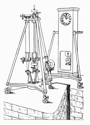
Figure 16.—From a Design Left by Bessel, this portable apparatus was developed in 1862 by the firm of Repsold in Hamburg, whose founder had assisted Bessel in the construction of his pendulum apparatus of 1826. The pendulum is convertible, but differs from Kater’s in being geometrically symmetrical and, for this reason, Repsold’s is usually called “reversible.” Just to the right of the pendulum is a standard scale. To the left is a “vertical comparator” designed by Repsold to measure the distance between the knife edges of the pendulum. To make this measurement, two micrometer microscopes which project horizontally through the comparator are alternately focused on the knife edges and on the standard scale.
Under the topic “Astronomical Questions,” the General Conference of 1864 resolved that there should be determinations of the intensity of gravity at the greatest possible number of points of the geodetic network, and recommended the reversible pendulum as the instrument of observation. [51] At the second General Conference, in Berlin in 1867, on the basis of favorable reports by Dr. Hirsch, director of the observatory at Neuchâtel, of Swiss practice with the Repsold-Bessel reversible pendulum, this instrument was specifically recommended for determinations of gravity. [52] The title of the association was changed to Die Europäische Gradmessung; in 1886, it became Die Internationale Erdmessung, under which title it continued until World War I.
On April 1, 1866, the Central Bureau of Die Europäische Gradmessung was opened in Berlin under the presidency of Baeyer, and in 1868 there was founded at Berlin, also under his presidency, the Royal Prussian Geodetic Institute, which obtained regular budgetary status on January 1, 1870. A reversible pendulum for the Institute was ordered from A. Repsold and Sons, and it was delivered in the spring of 1869. The Prussian instrument was symmetrical geometrically, as specified by Bessel, but different in form from the Swiss and Russian pendulums. The distance between the knife edges was 1 meter, and the time of swing approximately 1 second. The Prussian Repsold-Bessel pendulum was swung at Leipzig and other stations in central Europe during the years 1869-1870 by Dr. Albrecht under the direction of Dr. Bruhns, director of the observatory at Leipzig and chief of the astronomical section of the Geodetic Institute. The results of these first observations appeared in a publication of the Royal Prussian Geodetic Institute in 1871. [53]
Results of observations with the Russian Repsold-Bessel pendulums were published by the Imperial Academy of Sciences. In 1872, Prof. Sawitsch reported the work for western Europeans in “Les variations de la pesanteur dans les provinces occidentales de l’Empire russe.”[48] In November 1873, the Austrian Geodetic Commission received a Repsold-Bessel reversible pendulum and on September 24, 1874, Prof. Theodor von Oppolzer reported on observations at Vienna and other stations to the Fourth General Conference of Die Europäische Gradmessung in Dresden.[54] At the fourth session of the Conference, on September 28, 1874, a Special Commission, consisting of Baeyer, as chairman, and Bruhns, Hirsch, Von Oppolzer, Peters, and Albrecht, was appointed to consider (under Topic 3 of the program): “Observations for the determination of the intensity of gravity,” the question, “Which Pendulum-apparatuses are preferable for the determination of many points?”
After the adoption of the Repsold-Bessel reversible pendulum for gravity determinations in Europe, work in the field was begun by the U.S. Coast Survey under the superintendency of Prof. Benjamin Peirce. There is mention in reports of observations with pendulums prior to Peirce’s direction to his son Charles on November 30, 1872, “to take charge of the Pendulum Experiments of the Coast Survey and to direct and inspect all parties engaged in such experiments and as often as circumstances will permit, to take the field with a party….” [55] Systematic and important gravity work by the Survey was begun by Charles Sanders Peirce. Upon receiving notice of his appointment, the latter promptly ordered from the Repsolds a pendulum similar to the Prussian instrument. Since the firm of mechanicians was engaged in making instruments for observations of the transit of Venus in 1874, the pendulum for the Coast Survey could not be constructed immediately. Meanwhile, during the years 1873-1874, Charles Peirce conducted a party which made observations of gravity in the Hoosac Tunnel near North Adams, and at Northampton and Cambridge, Massachusetts. The pendulums used were nonreversible, invariable pendulums with conical bobs. Among them was a silver pendulum, but similar pendulums of brass were used also. [56]
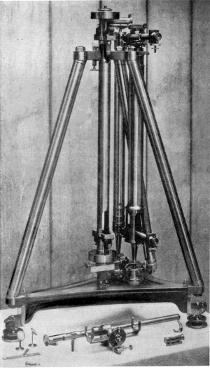
Figure 17.—Repsold-Bessel reversible pendulum apparatus as made in 1875, and used in the gravity work of the U.S. Coast and Geodetic Survey. Continental geodesists continued to favor the general use of convertible pendulums and absolute determinations of gravity, while their English colleagues had turned to invariable pendulums and relative determinations, except for base stations. Perhaps the first important American contribution to gravity work was C. S. Peirce’s demonstration of the error inherent in the Repsold apparatus through flexure of the stand.
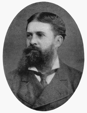
Figure 18.—Charles Sanders Peirce (1839-1914), son of Benjamin Peirce, Perkins Professor of Astronomy and Mathematics at Harvard College. C. S. Peirce graduated from Harvard in 1859. From 1873 to 1891, as an assistant at the U.S. Coast and Geodetic Survey, he accomplished the important gravimetric work described in this article. Peirce was also interested in many other fields, but above all in the logic, philosophy, and history of science, in which he wrote extensively. His greatest fame is in philosophy, where he is regarded as the founder of pragmatism.
In 1874, Charles Peirce expressed the desire to be sent to Europe for at least a year, beginning about March 1, 1875, “to learn the use of the new convertible pendulum and to compare it with those of the European measure of a Degree and the Swiss and to compare” his “invariable pendulums in the manner which has been used by swinging them in London and Paris.” [57]
Charles S. Peirce, assistant, U.S. Coast Survey, sailed for Europe on April 3, 1875, on his mission to obtain the Repsold-Bessel reversible pendulum ordered for the Survey and to learn the methods of using it for the determination of gravity. In England, he conferred with Maxwell, Stokes, and Airy concerning the theory and practice of research with pendulums. In May, he continued on to Hamburg and obtained delivery from the Repsolds of the pendulum for the Coast Survey (fig. 17). Peirce then went to Berlin and conferred with Gen. Baeyer, who expressed doubts of the stability of the Repsold stand for the pendulum. Peirce next went to Geneva, where, under arrangements with Prof. Plantamour, he swung the newly acquired pendulum at the observatory. [58]
In view of Baeyer’s expressed doubts of the rigidity of the Repsold stand, Peirce performed experiments to measure the flexure of the stand caused by the oscillations of the pendulum. His method was to set up a micrometer in front of the pendulum stand and, with a microscope, to measure the displacement caused by a weight passing over a pulley, the friction of which had been determined. Peirce calculated the correction to be applied to the length of the seconds pendulum—on account of the swaying of the stand during the swings of the pendulum—to amount to over 0.2 mm. Although Peirce’s measurements of flexure in Geneva were not as precise as his later measurements, he believed that failure to correct for flexure of the stand in determinations previously made with Repsold pendulums was responsible for appreciable errors in reported values of the length of the seconds pendulum.
The Permanent Commission of Die Europäische Gradmessung met in Paris, September 20-29, 1875. In conjunction with this meeting, there was held on September 21 a meeting of the Special Commission on the Pendulum. The basis of the discussion by the Special Commission was provided by reports which had been submitted in response to a circular sent out by the Central Bureau to the members on February 26, 1874. [59]
Gen. Baeyer stated that the distance of 1 meter between the knife edges of the Prussian Repsold-Bessel pendulum made it unwieldy and unsuited for transport. He declared that the instability of the stand also was a source of error. Accordingly, Gen. Baeyer expressed the opinion that absolute determinations of gravity should be made at a control station by a reversible pendulum hung on a permanent, and therefore stable stand, and he said that relative values of gravity with respect to the control station should be obtained in the field by means of a Bouguer invariable pendulum. Dr. Bruhns and Dr. Peters agreed with Gen. Baeyer; however, the Swiss investigators, Prof. Plantamour and Dr. Hirsch reported in defense of the reversible pendulum as a field instrument, as did Prof. von Oppolzer of Vienna. The circumstance that an invariable pendulum is subject to changes in length was offered as an argument in favor of the reversible pendulum as a field instrument.
Peirce was present during these discussions by the members of the Special Commission, and he reported that his experiments at Geneva demonstrated that the oscillations of the pendulum called forth a flexure of the support which hitherto had been neglected. The observers who used the Swiss and Austrian Repsold pendulums contended, in opposition to Peirce, that the Repsold stand was stable.
The outcome of these discussions was that the Special Commission reported to the Permanent Commission that the Repsold-Bessel reversible pendulum, except for some small changes, satisfied all requirements for the determination of gravity. The Special Commission proposed that the Repsold pendulums of the several states be swung at the Prussian Eichungsamt in Berlin where, as Peirce pointed out, Bessel had made his determination of the intensity of gravity with a ball pendulum in 1835. Peirce was encouraged to swing the Coast Survey reversible pendulum at the stations in France, England, and Germany where Borda and Cassini, Kater, and Bessel, respectively, had made historic determinations. The Permanent Commission, in whose sessions Peirce also participated, by resolutions adopted the report of the Special Commission on the Pendulum. [60]
During the months of January and February 1876, Peirce conducted observations in the Grande Salle du Meridien at the observatory in Paris where Borda, Biot, and Capt. Edward Sabine had swung pendulums early in the 19th century. He conducted observations in Berlin from April to June 1876 and, by experiment, determined the correction for flexure to be applied to the value of gravity previously obtained with the Prussian instrument. Subsequent observations were made at Kew. After his return to the United States on August 26, 1876, Peirce conducted experiments at the Stevens Institute in Hoboken, New Jersey, where he made careful measurements of the flexure of the stand by statical and dynamical methods. In Geneva, he had secured the construction of a vacuum chamber in which the pendulum could be swung on a support which he called the Geneva support. At the Stevens Institute, Peirce swung the Repsold-Bessel pendulum on the Geneva support and determined the effect of different pressures and temperatures on the period of oscillation of the pendulum. These experiments continued into 1878. [61]
Meanwhile, the Permanent Commission met October 5-10, 1876, in Brussels and continued the discussion of the pendulum. [62] Gen. Baeyer reported on Peirce’s experiments in Berlin to determine the flexure of the stand. The difference of 0.18 mm. in the lengths of the seconds pendulum as determined by Bessel and as determined by the Repsold instrument agreed with Peirce’s estimate of error caused by neglect of flexure of the Repsold stand. Dr. Hirsch, speaking for the Swiss survey, and Prof. von Oppolzer, speaking for the Austrian survey, contended, however, that their stands possessed sufficient stability and that the results found by Peirce applied only to the stands and bases investigated by him. The Permanent Commission proposed further study of the pendulum.
The Fifth General Conference of Die Europäische Gradmessung was held from September 27 to October 2, 1877, in Stuttgart. [63] Peirce had instructions from Supt. Patterson of the U.S. Coast Survey to attend this conference, and on arrival presented a letter of introduction from Patterson requesting that he, Peirce, be permitted to participate in the sessions. Upon invitation from Prof. Plantamour, as approved by Gen. Ibañez, president of the Permanent Commission, Peirce had sent on July 13, 1877, from New York, the manuscript of a memoir titled “De l’Influence de la flexibilité du trépied sur l’oscillation du pendule à réversion.” This memoir and others by Cellérier and Plantamour confirming Peirce’s work were published as appendices to the proceedings of the conference. As appendices to Peirce’s contribution were published also two notes by Prof. von Oppolzer. At the second session on September 29, 1877, when Plantamour reported that the work of Hirsch and himself had confirmed experimentally the independent theoretical work of Cellérier and the theoretical and experimental work of Peirce on flexure, Peirce described his Hoboken experiments.
During the discussions at Stuttgart on the flexure of the Repsold stand, Hervé Faye, president of the Bureau of Longitudes, Paris, suggested that the swaying of the stand during oscillations of the pendulum could be overcome by the suspension from one support of two similar pendulums which oscillated with equal amplitudes and in opposite phases. This proposal was criticized by Dr. Hirsch, who declared that exact observation of passages of a “double pendulum” would be difficult and that two pendulums swinging so close together would interfere with each other. The proposal of the double pendulum came up again at the meeting of the Permanent Commission at Geneva in 1879. [64] On February 17, 1879, Peirce had completed a paper “On a Method of Swinging Pendulums for the Determination of Gravity, Proposed by M. Faye.” In this paper, Peirce presented the results of an analytical mechanical investigation of Faye’s proposal. Peirce set up the differential equations, found the solutions, interpreted them physically, and arrived at the conclusion “that the suggestion of M. Faye … is as sound as it is brilliant and offers some peculiar advantages over the existing method of swinging pendulums.”
In a report to Supt. Patterson, dated July 1879, Peirce stated: “I think it is important before making a new pendulum apparatus to experiment with Faye’s proposed method.” [65] He wrote further: “The method proves to be perfectly sound in theory, and as it would greatly facilitate the work it is probably destined eventually to prevail. We must unfortunately leave to other surveys the merit of practically testing and introducing the new method, as our appropriations are insufficient for us to maintain the leading position in this matter, which we otherwise might take.” Copies of the published version of Peirce’s remarks were sent to Europe. At a meeting of the Academy of Sciences in Paris on September 1, 1879, Faye presented a report on Peirce’s findings. [66] The Permanent Commission met September 16-20, 1879, in Geneva. At the third session on September 19, by action of Gen. Baeyer, copies of Peirce’s paper on Faye’s proposed method of swinging pendulums were distributed. Dr. Hirsch again commented adversely on the proposal, but moved that the question be investigated and reported on at the coming General Conference. The Permanent Commission accepted the proposal of Dr. Hirsch, and Prof. Plantamour was named to report on the matter at the General Conference. At Plantamour’s request, Charles Cellérier was appointed to join him, since the problem essentially was a theoretical one.
The Sixth General Conference of Die Europäische Gradmessung met September 13-16, 1880, in Munich. [67] Topic III, part 7 of the program was entitled “On Determinations of Gravity through pendulum observations. Which construction of a pendulum apparatus corresponds completely to all requirements of science? Special report on the pendulum.”
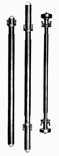
Figure 19.—Three pendulums used in early work at the U.S. Coast and Geodetic Survey. Shown on the left is the Peirce invariable; center, the Peirce reversible; and, right, the Repsold reversible. Peirce designed the cylindrical pendulum in 1881-1882 to study the effect of air resistance according to the theory of G. G. Stokes on the motion of a pendulum in a viscous field. Three examples of the Peirce pendulums are in the U.S. National Museum.
The conference received a memoir by Cellérier [68] on the theory of the double pendulum and a report by Plantamour and Cellérier. [69] Cellérier’s mathematical analysis began with the equations of Peirce and used the latter’s notation as far as possible. His general discussion included the results of Peirce, but he stated that the difficulties to be overcome did not justify the employment of the “double pendulum.” He presented an alternative method of correcting for flexure based upon a theory by which the flexure caused by the oscillation of a given reversible pendulum could be determined from the behavior of an auxiliary pendulum of the same length but of different weight. This method of correcting for flexure was recommended to the General Conference by Plantamour and Cellérier in their joint report. At the fourth session of the conference on September 16, 1880, the problem of the pendulum was discussed and, in consequence, a commission consisting of Faye, Helmholtz, Plantamour (replaced in 1882 by Hirsch), and Von Oppolzer was appointed to study apparatus suitable for relative determinations of gravity.
The Permanent Commission met September 11-15, 1882, at The Hague, [70] and at its last session appointed Prof. von Oppolzer to report to the Seventh General Conference on different forms of apparatus for the determination of gravity. The Seventh Conference met October 15-24, 1883, in Rome, [71] and, at its eighth session, on October 22, received a comprehensive, critical review from Prof. von Oppolzer entitled “Über die Bestimmung der Schwere mit Hilfe verschiedener Apparate.” [72] Von Oppolzer especially expounded the advantages of the Bessel reversible pendulum, which compensated for air effects by symmetry of form if the times of swing for both positions were maintained between the same amplitudes, and compensated for irregular knife edges by making them interchangeable. Prof. von Oppolzer reviewed the problem of flexure of the Repsold stand and stated that a solution in the right direction was the proposal—made by Faye and theoretically pursued by Peirce—to swing two pendulums from the same stand with equal amplitudes and in opposite phases, but that the proposal was not practicable. He concluded that for absolute determinations of gravity, the Bessel reversible pendulum was highly appropriate if one swung two exemplars of different weight from the same stand for the elimination of flexure. Prof. von Oppolzer’s important report recognized that absolute determinations were less accurate than relative ones, and should be conducted only at special places.
The discussions initiated by Peirce’s demonstration of the flexure of the Repsold stand resulted, finally, in the abandonment of the plan to make absolute determinations of gravity at all stations with the reversible pendulum.
Peirce and Defforges Invariable, Reversible Pendulums
The Repsold-Bessel reversible pendulum was designed and initially used to make absolute determinations of gravity not only at initial stations such as Kew, the observatory in Paris, and the Smithsonian Institution in Washington, D.C., but also at stations in the field. An invariable pendulum with a single knife edge, however, is adequate for relative determinations. As we have seen, such invariable pendulums had been used by Bouguer and Kater, and after the experiences with the Repsold apparatus had been recommended again by Baeyer for relative determinations. But an invariable pendulum is subject to uncontrollable changes of length. Peirce proposed to detect such changes in an invariable pendulum in the field by combining the invariable and reversible principles. He explained his proposal to Faye in a letter dated July 23, 1880, and he presented it on September 16, 1880, at the fourth session of the sixth General Conference of Die Europäische Gradmessung, in Munich. [73]
As recorded in the Proceedings of the Conference, Peirce wrote:
But I obviate it in making my pendulum both invariable and reversible. Every alteration of the pendulum will be revealed immediately by the change in the difference of the two periods of oscillation in the two positions. Once discovered, it will be taken account of by means of new measures of the distance between the two supports.
Peirce added that it seemed to him that if the reversible pendulum perhaps is not the best instrument to determine absolute gravity, it is, on condition that it be truly invariable, the best to determine relative gravity. Peirce further stated that he would wish that the pendulum be formed of a tube of drawn brass with heavy plugs of brass equally drawn. The cylinder would be terminated by two hemispheres; the knives would be attached to tongues fixed near the ends of the cylinder.
During the years 1881 and 1882, four invariable, reversible pendulums were made after the design of Peirce at the office of the U.S. Coast and Geodetic Survey in Washington, D.C. The report of the superintendent for the year 1880-1881 states:
A new pattern of the reversible pendulum has been invented, having its surface as nearly as convenient in the form of an elongated ellipsoid. Three of these instruments have been constructed, two having a distance of one meter between the knife edges and the third a distance of one yard. It is proposed to swing one of the meter pendulums at a temperature near 32° F. at the same time that the yard is swung at 60° F., in order to determine anew the relation between the yard and the meter. [74]
The report for 1881-1882 mentions four of these Peirce pendulums.
A description of the Peirce invariable, reversible pendulums was given by Assistant E. D. Preston in “Determinations of Gravity and the Magnetic Elements in Connection with the United States Scientific Expedition to the West Coast of Africa, 1889-90.” [75] The invariable, reversible pendulum, Peirce no. 4, now preserved in the Smithsonian Institution’s Museum of History and Technology (fig. 34), may be taken as typical of the meter pendulums: In the same memoir, Preston gives the diameter of the tube as 63.7 mm., thickness of tube 1.5 mm., weight 10.680 kilograms, and distance between the knives 1.000 meter.
The combination of invariability and reversibility in the Peirce pendulums was an innovation for relative determinations. Indeed, the combination was criticized by Maj. J. Herschel, R.E., of the Indian Survey, at a conference on gravity held in Washington in May 1882 on the occasion of his visit to the United States for the purpose of connecting English and American stations by relative determinations with three Kater invariable pendulums. These three pendulums have been designated as nos. 4, 6 (1821), and 11. [76]
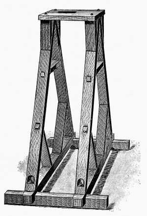
Figure 20.—Support for the Peirce pendulum, 1889. Much of the work of C. S. Peirce was concerned with the determination of the error introduced into observations made with the portable apparatus by the vibration of the stand with the pendulum. He showed that the popular Bessel-Repsold apparatus was subject to such an error. His own pendulums were swung from a simple but rugged wooden frame to which a hardened steel bearing was fixed.
Another novel characteristic of the Peirce pendulums was the mainly cylindrical form. Prof. George Gabriel Stokes, in a paper “On the Effect of the Internal Friction of Fluids on the Motion of Pendulums” [77] that was read to the Cambridge Philosophical Society on December 9, 1850, had solved the hydrodynamical equations to obtain the resistance to the motions of a sphere and a cylinder in a viscous fluid. Peirce had studied the effect of viscous resistance on the motion of his Repsold-Bessel pendulum, which was symmetrical in form but not cylindrical. The mainly cylindrical form of his pendulums (fig. 19) permitted Peirce to predict from Stokes’ theory the effect of viscosity and to compare the results with experiment. His report of November 20, 1889, in which he presented the comparison of experimental results with the theory of Stokes, was not published. [78]
Peirce used his pendulums in 1883 to establish a station at the Smithsonian Institution that was to serve as the base station for the Coast and Geodetic Survey for some years. Pendulum Peirce no. 1 was swung at Washington in 1881 and was then taken by the party of Lieutenant Greely, U.S.A., on an expedition to Lady Franklin Bay where it was swung in 1882 at Fort Conger, Grinnell Land, Canada. Peirce nos. 2 and 3 were swung by Peirce in 1882 at Washington, D.C.; Hoboken, New Jersey; Montreal, Canada; and Albany, New York. Assistant Preston took Peirce no. 3 on a U.S. eclipse expedition to the Caroline Islands in 1883. Peirce in 1885 swung pendulums nos. 2 and 3 at Ann Arbor, Michigan; Madison, Wisconsin; and Ithaca, New York. Assistant Preston in 1887 swung Peirce nos. 3 and 4 at stations in the Hawaiian Islands, and in 1890 he swung Peirce nos. 3 and 4 at stations on the west coast of Africa. [79]
Pendulums of 1-meter and of 1/2-meter distance between the knife edges were constructed from Defforges’ design by Brunner Brothers in Paris (fig. 21). These Defforges pendulums were cylindrical in form with hemispherical ends like the Peirce pendulums, and were hung on knives that projected from the sides of the pendulum, as in some unfinished Gautier pendulums designed by Peirce in 1883 in Paris.
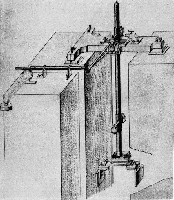
Figure 21.—Reversible pendulum apparatus of Defforges, as constructed by Brunner, Paris, about 1887. The clock and telescope used to observe coincidences are not shown. The telescope shown is part of an interferometer used to measure flexure of the support. One mirror of the interferometer is attached to the pendulum support; the other to the separate masonry pillar at the left.
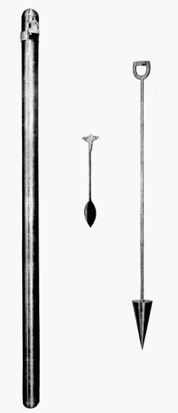
Figure 22.—Because of the greater simplicity of its use, the invariable pendulum superseded the convertible pendulum towards the end of the 19th century, except at various national base stations (Kew, Paris, Potsdam, Washington, D.C., etc.). Shown here are, right to left, a pendulum of the type used by Peirce at the Hoosac Tunnel in 1873-74, the Mendenhall 1/2-second pendulum of 1890, and the pendulum designed by Peirce in 1881-1882.
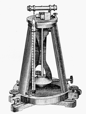
Figure 23.—The overall size of portable pendulum apparatus was greatly reduced with the introduction of this 1/2-second apparatus in 1887, by the Austrian military officer, Robert von Sterneck. Used with a vacuum chamber not shown here, the apparatus is only about 2 feet high. Coincidences are observed by the reflection of a periodic electric spark in two mirrors, one on the support and the other on the pendulum itself.
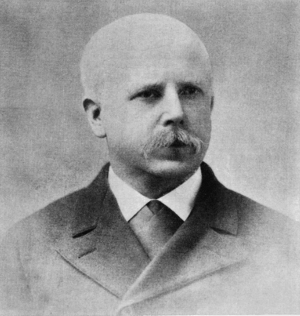
Figure 24.—Thomas C. Mendenhall (1841-1924). Although largely self-educated, he became the first professor of physics and mechanics at the Ohio Agricultural and Mechanical College (later Ohio State University), and was subsequently connected with several other universities. In 1878, while teaching at the Tokyo Imperial University in Japan, he made gravity measurements between Tokyo and Fujiyama from which he calculated the mean density of the earth. While superintendent of the U.S. Coast and Geodetic Survey, 1889-94, he developed the pendulum apparatus which bears his name.
Von Sterneck and Mendenhall Pendulums
By 1887 Maj. von Sterneck had perfected his apparatus, and it was widely adopted in Europe for relative determinations of gravity. He used his apparatus in extensive gravity surveys and also applied it in the silver mines in Saxony and Bohemia, by the previously described methods of Airy, for investigations into the internal constitution of the earth.
Like the Von Sterneck apparatus, the Mendenhall pendulum apparatus employed a nonreversible, invariable pendulum 1/4-meter in length and of slightly more than 1/2-second in time of swing. Initially, the knife edge was placed in the head of the pendulum and hung on a fixed plane support, but after some experimentation Mendenhall attached the plane surface to the pendulum and hung it on a fixed knife edge. An apparatus was provided with a set of three pendulums, so that if discrepancies appeared in the results, the pendulum at fault could be detected. There was also a dummy pendulum which carried a thermometer. A pendulum was swung in a receiver in which the pressure and temperature of the air were controlled. The time of swing was measured by coincidences with the beat of a chronometer. The coincidences were determined by an optical method with the aid of a flash apparatus.
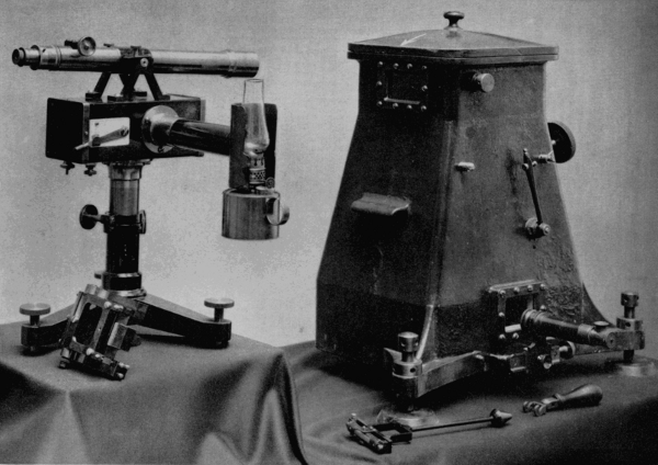
Figure 25.—Mendenhall’s 1/4-meter (1/2-second) apparatus. Shown on the left is the flash apparatus and, on the right, the vacuum chamber within which the pendulum is swung. The flash apparatus consists of a kerosene lantern and a telescope, mounted on a box containing an electromagnetically operated shutter. The operation of the shutter is controlled by a chronograph (not shown), so that it emits a slit of light at regular intervals. The telescope is focused on two mirrors within the apparatus, one fixed, the other attached to the top of the pendulum. It is used to observe the reflection of the flashes from these mirrors. When the two reflections are aligned, a “coincidence” is marked on the chronograph tape. The second telescope attached to the bottom of the vacuum chamber is for observing the amplitude of the pendulum swing.
The flash apparatus was contained in a light metal box which supported an observing telescope and which was mounted on a stand. Within the box was an electromagnet whose coils were connected with a chronometer circuit and whose armature carried a long arm that moved two shutters, in both of which were horizontal slits of the same size. The shutters were behind the front face of the box, which also had a horizontal slit. A flash of light from an oil lamp or an electric spark was emitted from the box when the circuit was broken, but not when it was closed. When the circuit was broken a spring caused the arm to rise, and the shutters were actuated so that the three slits came into line and a flash of light was emitted. A small circular mirror was set in each side of the pendulum head, so that from either face of the pendulum the image of the illuminated slit could be reflected into the field of the observing telescope. A similar mirror was placed parallel to these two mirrors and rigidly attached to the support. The chronometer signals broke the circuit, causing the three slits momentarily to be in line, and when the images of the slit in the two mirrors coincided, a coincidence was observed. A coincidence occurred whenever the pendulum gained or lost one oscillation on the beat of the chronometer. The relative intensity of gravity was determined by observations with the first Mendenhall apparatus at Washington, D.C., at stations on the Pacific Coast and in Alaska, and at the Stevens Institute, Hoboken, New Jersey, between March and October 1891.
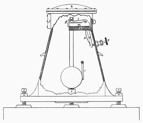
Figure 26.—Vacuum receiver within which the Mendenhall pendulum is swung. The pressure is reduced to about 50 mm. to reduce the disturbing effect of air resistance. When the apparatus is sealed, the pendulum is lifted on the knife edge by the lever q and is started to swing by the lever r. The arc of swing is only about 1°. The stationary mirror is shown at g. The pendulum shown in outline in the center, is only about 9.7 inches long.
Under Supt. Mendenhall’s direction a smaller, 1/4-second, pendulum apparatus was also constructed and tested, but did not offer advantages over the 1/2-second apparatus, which therefore continued in use.
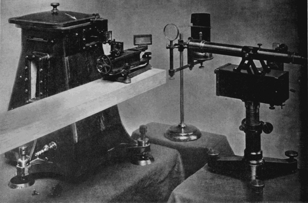
Figure 27.—The Michelson interferometer. The horizontal component of the force acting on the knife edge through the swinging pendulum causes the support to move in unison with the pendulum, and thereby affects the period of the oscillation. This movement is the so-called flexure of the pendulum support, and must be taken into account in the most accurate observations.
In 1907, the Michelson interferometer was adapted to this purpose by the U.S. Coast and Geodetic Survey. As shown here, the interferometer, resting on a wooden beam, is introduced into the path of a light beam reflected from a mirror on the vacuum chamber. Movement of that mirror causes a corresponding movement in the interference fringes in the interferometer, which can be measured.
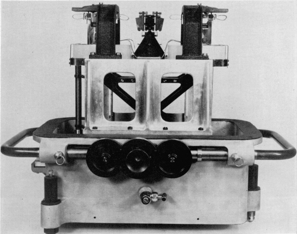
Figure 28.—Apparatus which was developed in 1929 by the Gulf Research and Development Company, Harmarville, Pennsylvania. It was designed to achieve an accuracy within one ten-millionth of the true value of gravity, and represents the extreme development of pendulum apparatus for relative gravity measurement. The pendulum was designed so that the period would be a minimum. The case (the top is missing in this photograph) is dehumidified and its temperature and electrostatic condition are controlled. Specially designed pendulum-lifting and -starting mechanisms are used. The problem of flexure of the case is overcome by the Faye-Peirce method (see text) in which two dynamically matched pendulums are swung simultaneously, 180° apart in phase.
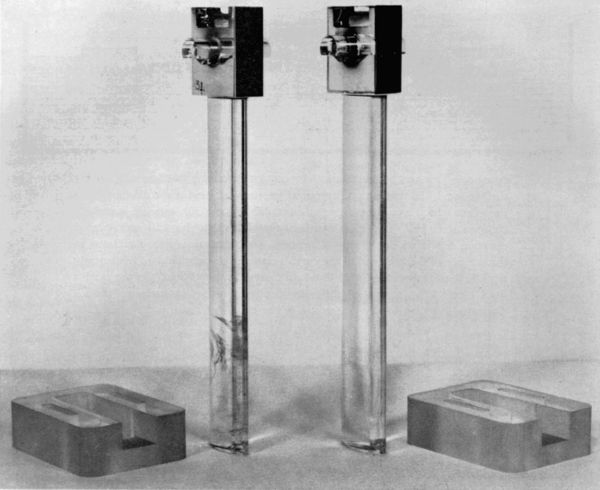
Figure 29.—The Gulf pendulum is about 10.7 inches long, and has a period of .89 second. It is made of fused quartz which is resistant to the influence of temperature change and to the earth’s magnetism. Quartz pendulums are subject to the influence of electrostatic charge, and provision is made to counteract this through the presence of a radium salt in the case. The bearings are made of Pyrex glass.
The best way to eliminate the effect of flexure is to use two synchronized pendulums of the same length swinging on the same apparatus in the same plane and with the same amplitudes but in opposite phases; it is clear then the flexure is zero. [95]
In view of the fact that the symmetrical reversible pendulum is named for Bessel, who created the theory and a design for its application by Repsold, it appears appropriate to call the method of eliminating flexure by swinging two pendulums on the same support the Faye-Peirce method. Its successful application was made possible by Maj. von Sterneck’s invention of the short, 1/4-meter pendulum.
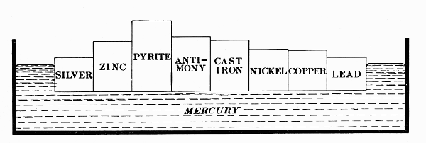
Figure 30.—The accumulated data of gravity observations over the earth’s surface have indicated that irregularities such as mountains do not have the effect which would be expected in modifying gravity, but are somehow compensated for. The most satisfactory solution to this still unanswered question has been the theory of isostasy, according to which variations in the density of the material in the earth’s crust produce a kind of hydrostatic equilibrium between its higher and lower parts, as they “float” on the earth’s fluid core. The metals of different density floating in mercury in this diagram illustrate isostasy according to the theory of Pratt and Hayford.
Absolute Value of Gravity at Potsdam
The development of the reversible pendulum in the 19th century culminated in the absolute determination of the intensity of gravity at Potsdam by Kühnen and Furtwängler of the Royal Prussian Geodetic Institute, which then became the world base for gravity surveys. [96]
We have previously seen that in 1869 the Geodetic Institute—founded by Lt. Gen. Baeyer—had acquired a Repsold-Bessel reversible pendulum which was swung by Dr. Albrecht under the direction of Dr. Bruhns. Dissatisfaction with this instrument was expressed by Baeyer in 1875 to Charles S. Peirce, who then, by experiment and mathematical analysis of the flexure of the stand under oscillations of the pendulum, determined that previously reported results with the Repsold apparatus required correction. Dr. F. R. Helmert, who in 1887 succeeded Baeyer as director of the Institute, secured construction of a building for the Institute in Potsdam, and under his direction the scientific study of the intensity of gravity was pursued with vigor. In 1894, it was discovered in Potsdam that a pendulum constructed of very flexible material yielded results which differed markedly from those obtained with pendulums of greater stiffness. Dr. Kühnen of the Institute discovered that the departure from expectations was the result of the flexure of the pendulum staff itself during oscillations. [97]
Peirce, in 1883, had discovered that the recesses cut in his pendulums for the insertion of tongues that carried the knives had resulted in the flexure of the pendulum staff. [98] By experiment, he also found an even greater flexure for the Repsold pendulum. In order to eliminate this source of error, Peirce designed a pendulum with knives that extended from each side of the cylindrical staff, and he received authorization from the superintendent of the Coast and Geodetic Survey to arrange for the construction of such pendulums by Gautier in Paris. Peirce, who had made his plans in consultation with Gautier, was called home before the pendulums were completed, and these new instruments remained undelivered.
In a memoir titled “Effect of the flexure of a pendulum upon its period of oscillation,” [99] Peirce determined analytically the effect on the period of a pendulum with a single elastic connection between two rigid parts of the staff. Thus, Peirce discovered experimentally the flexure of the staff and derived for a simplified case the effect on the period. It is not known if he ever found the integrated effect of the continuum of elastic connections in the pendulum. Lorenzoni, in 1896, offered a solution to the problem, and Almansi, in 1899, gave an extended analysis. After the independent discovery of the problem at the Geodetic Institute, Dr. Helmert took up the problem and criticized the theories of Peirce and Lorenzoni. He then presented his own theory of flexure in a comprehensive memoir. [100] In view of the previous neglect of the flexure of the pendulum staff in the reduction of observations, Helmert directed that the Geodetic Institute make a new absolute determination of the intensity of gravity at Potsdam. For this purpose, Kühnen and Furtwängler used the following reversible pendulums which had been constructed by the firm of A. Repsold and Sons in Hamburg:
1. The seconds pendulum of the Geodetic Institute procured in 1869.
2. A seconds pendulum from the Astronomical Observatory, Padua.
3. A heavy, seconds pendulum from the Imperial and Royal Military-Geographical Institute, Vienna.
4. A light, seconds pendulum from the Imperial and Royal Military-Geographical Institute.
5. A 1/2-second, reversible pendulum of the Geodetic Institute procured in 1892.
Work was begun in 1898, and in 1906 Kühnen and Furtwängler published their monumental memoir, “Bestimmung der Absoluten Grösze der Schwerkraft zu Potsdam mit Reversionspendeln.”
The acceleration of gravity in the pendulum room of the Geodetic Institute was determined to be 981.274 ± 0.003 cm/sec2. In view of the exceptionally careful and thorough determination at the Institute, Potsdam was accepted as the world base for the absolute value of the intensity of gravity. The absolute value of gravity at some other station on the Potsdam system was determined from the times of swing of an invariable pendulum at the station and at Potsdam by the relation T12/T22 = g2/g1. Thus, in 1900, Assistant G. R. Putnam of the Coast and Geodetic Survey swung Mendenhall pendulums at the Washington base and at Potsdam, and by transfer from Potsdam determined the intensity of gravity at the Washington base to be 980.112 cm/sec2. [101] In 1933, Lt. E. J. Brown made comparative measurements with improved apparatus and raised the value at the Washington base to 980.118 cm/sec2. [102]
In view of discrepancies between the results of various relative determinations, the Coast and Geodetic Survey in 1928 requested the National Bureau of Standards to make an absolute determination for Washington. Heyl and Cook used reversible pendulums made of fused silica having a period of approximately 1 second. Their result, published in 1936, was interpreted to indicate that the value at Potsdam was too high by 20 parts in 1 million. [103] This estimate was lowered slightly by Sir Harold Jeffreys of Cambridge, England, who recomputed the results of Heyl and Cook by different methods. [104]
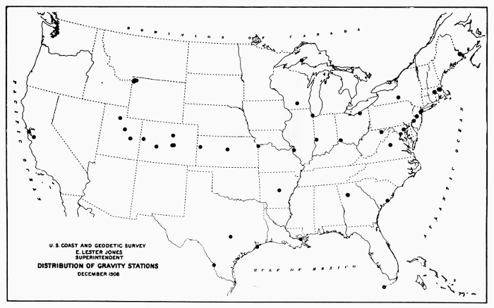
Figure 31.—Map showing the distribution of gravity stations throughout the United States as of December 1908.
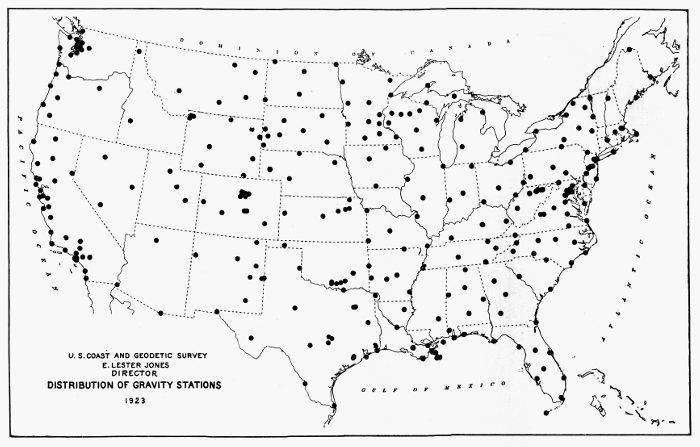
Figure 32.—Map showing the distribution of gravity stations throughout the United States in 1923.
In 1939, J. S. Clark published the results of a determination of gravity with pendulums of a non-ferrous Y-alloy [105] at the National Physical Laboratory at Teddington, England, and, after recomputation of results by Jeffreys, the value was found to be 12.8 parts in 1 million less than the value obtained by transfer from Potsdam. Dr. Hugh L. Dryden of the National Bureau of Standards, and Dr. A. Berroth of the Geodetic Institute at Potsdam, have recomputed the Potsdam data by different methods of adjustment and concluded that the Potsdam value was too high by about 12 parts in a million. [106] Determination of gravity at Leningrad by Russian scientists likewise has indicated that the 1906 Potsdam value is too high. In the light of present information, it appears justifiable to reduce the Potsdam value of 981.274 by .013 cm/sec2 for purposes of comparison. If the Brown transfer from Potsdam in 1933 was taken as accurate, the value for the Washington base would be 980.105 cm/sec2. In this connection, it is of interest to note that the value given by Charles S. Peirce for the comparable Smithsonian base in Washington, as determined by him from comparative methods in the 1880’s and reported in the Annual Report of the Superintendent of the Coast and Geodetic Survey for the year 1890-1891, was 980.1017 cm/sec2. [107] This value would appear to indicate that Peirce’s pendulums, observations, and methods of reduction of data were not inferior to those of the scientists of the Royal Prussian Geodetic Institute at Potsdam.
Doubts concerning the accuracy of the Potsdam value of gravity have stimulated many new determinations of the intensity of gravity since the end of World War II. In a paper published in June 1957, A. H. Cook, Metrology Division, National Physical Laboratory, Teddington, England, stated:
At present about a dozen new absolute determinations are in progress or are being planned. Heyl and Cook’s reversible pendulum apparatus is in use in Buenos Aires and further reversible pendulum experiments have been made in the All Union Scientific Research Institute of Metrology, Leningrad (V N I I M) and are planned at Potsdam. A method using a very long pendulum was tried out in Russia about 1910 and again more recently and there are plans for similar work in Finland. The first experiment with a freely falling body was that carried out by Volet who photographed a graduated scale falling in an enclosure at low air pressure. Similar experiments have been completed in Leningrad and are in progress at the Physikalisch-Technische Bundesanstalt (Brunswick) and at the National Research Council (Ottawa), and analogous experiments are being prepared at the National Physical Laboratory and at the National Bureau of Standards. Finally, Professor Medi, Director of the Istituto Nazionale di Geofisica (Rome), is attempting to measure the focal length of the paraboloidal surface of a liquid in a rotating dish. [108]
Application of Gravity Surveys
We have noted previously that in the ancient and early modern periods, the earth was presupposed to be spherical in form. Determination of the figure of the earth consisted in the measurement of the radius by the astronomical-geodetic method invented by Eratosthenes. Since the earth was assumed to be spherical, gravity was inferred to be constant over the surface of the earth. This conclusion appeared to be confirmed by the determination of the length of the seconds pendulum at various stations in Europe by Picard and others. The observations of Richer in South America, the theoretical discussions of Newton and Huygens, and the measurements of degrees of latitude in Peru and Sweden demonstrated that the earth is an oblate spheroid.
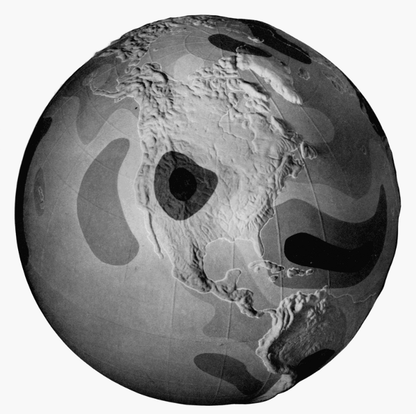
Figure 33.—Gravity characteristics of the globe. Deductions as to the distribution of matter in the earth can be made from gravity measurements. This globe shows worldwide variations in gravity as they now appear from observations at sea (in submarines) as well as on land. It is based on data from the Institute of Geodesy at Ohio State University.
The theory of gravitation and the theory of central forces led to the result that the intensity of gravity is variable over the surface of the earth. Accordingly, determinations of the intensity of gravity became of value to the geodesist as a means of determining the figure of the earth. Newton, on the basis of the meager data available to him, calculated the ellipticity of the earth to be 1/230 (the ellipticity is defined by (a-b)/a, where a is the equatorial radius and b the polar radius). Observations of the intensity of gravity were made on the historic missions to Peru and Sweden. Bouguer and La Condamine found that at the equator at sea level the seconds pendulum was 1.26 Paris-lines shorter than at Paris. Maupertuis found that in northern Sweden a certain pendulum clock gained 59.1 seconds per day on its rate in Paris. Then Clairaut, from the assumption that the earth is a spheroid of equilibrium, derived a theorem from which the ellipticity of the earth can be derived from values of the intensity of gravity.
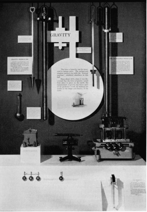
Figure 34.—An exhibit of gravity apparatus at the Smithsonian Institution. Suspended on the wall, from left to right, are the invariable pendulums of Mendenhall (1/2-second), Peirce (1873-1874), and Peirce (1881-1882); the double pendulum of Edward Kübel (see fig. 15, p. 319), and the reversible pendulum of Peirce. On the display counter, from left to right, are the vacuum chamber, telescope and flash apparatus for the Mendenhall 1/4-second apparatus. Shown below these are the four pendulums used with the Mendenhall apparatus, the one on the right having a thermometer attached. At bottom, right, is the Gulf apparatus (cover removed) mentioned in the text, shown with one quartz pendulum.
Early in the 19th century a systematic series of observations began to be conducted in order to determine the intensity of gravity at stations all over the world. Kater invariable pendulums, of which 13 examples have been mentioned in the literature, were used in surveys of gravity by Kater, Sabine, Goldingham, and other British pendulum swingers. As has been noted previously, a Kater invariable pendulum was used by Adm. Lütke of Russia on a trip around the world. The French also sent out expeditions to determine values of gravity. After several decades of relative inactivity, Capts. Basevi and Heaviside of the Indian Survey carried out an important series of observations from 1865 to 1873 with Kater invariable pendulums and the Russian Repsold-Bessel pendulums. In 1881-1882 Maj. J. Herschel swung Kater invariable pendulums nos. 4, 6 (1821), and 11 at stations in England and then brought them to the United States in order to make observations which would connect American and English base stations. [109]
The extensive sets of observations of gravity provided the basis of calculations of the ellipticity of the earth. Col. A. R. Clarke in his Geodesy (London, 1880) calculated the ellipticity from the results of gravity surveys to be 1/(292.2 ± 1.5). Of interest is the calculation by Charles S. Peirce, who used only determinations made with Kater invariable pendulums and corrected for elevation, atmospheric effect, and expansion of the pendulum through temperature.[110] He calculated the ellipticity of the earth to be 1/(291.5 ± 0.9).
The 19th century witnessed the culmination of the ellipsoidal era of geodesy, but the rapid accumulation of data made possible a better approximation to the figure of the earth by the geoid. The geoid is defined as the average level of the sea, which is thought of as extended through the continents. The basis of geodetic calculations, however, is an ellipsoid of reference for which a gravity formula expresses the value of normal gravity at a point on the ellipsoid as a function of gravity at sea level at the equator, and of latitude. The general assembly of the International Union of Geodesy and Geophysics, which was founded after World War I to continue the work of Die Internationale Erdmessung, adopted in 1924 an international reference ellipsoid, [111] of which the ellipticity, or flattening, is Hayford’s value 1/297. In 1930, the general assembly adopted a correlated International Gravity Formula of the form γ = γE(1 + β(sin2 φ) + ε(sin2 2φ)) where γ is normal gravity at latitude φ, γE is the value of gravity at sea level at the equator, β is a parameter which is computed on the basis of Clairaut’s theorem from the flattening value of the meridian, and ε is a constant which is derived theoretically. The plumb line is perpendicular to the geoid, and the components of angle between the perpendiculars to geoid and reference ellipsoid are deflections of the vertical. The geoid is above the ellipsoid of reference under mountains and it is below the ellipsoid on the oceans, where the geoid coincides with mean sea level. In physical geodesy, gravimetric data are used for the determination of the geoid and components of deflections of the vertical. For this purpose, one must reduce observed values of gravity to sea level by various reductions, such as free-air, Bouguer, isostatic reductions. If g0 is observed gravity reduced to sea level and γ is normal gravity obtained from the International Gravity Formula, then Δg = g0 - γ is the gravity anomaly. [112]
In 1849, Stokes derived a theorem whereby the distance N of the geoid from the ellipsoid of reference can be obtained from an integration of gravity anomalies over the surface of the earth. Vening Meinesz further derived formulae for the calculation of components of the deflection of the vertical.
Geometrical geodesy, which was based on astronomical-geodetic methods, could give information only concerning the external form of the figure of the earth. The gravimetric methods of physical geodesy, in conjunction with methods such as those of seismology, enable scientists to test hypotheses concerning the internal structure of the earth. Heiskanen and Vening Meinesz summarize the present-day achievements of the gravimetric method of physical geodesy by stating [113] that it alone can give:
1. The flattening of the reference ellipsoid.
2. The undulations N of the geoid.
3. The components of the deflection of the vertical ζ and η at any point, oceans and islands included.
4. The conversion of existing geodetic systems to the same world geodetic system.
5. The reduction of triangulation base lines from the geoid to the reference ellipsoid.
6. The correction of errors in triangulation in mountainous regions due to the effect of the deflections of the vertical.
7. Geophysical applications of gravity measurements, e.g., the isostatic study of the earth’s interior and the exploration of oil fields and ore deposits.
With astronomical observations or with existing triangulations, the gravimetric method can accomplish further results. Heiskanen and Vening Meinesz state:
It is the firm conviction of the authors that the gravimetric method is by far the best of the existing methods for solving the main problems of geodesy, i.e., to determine the shape of the geoid on the continents as well as at sea and to convert the existing geodetic systems to the world geodetic system. It can also give invaluable help in the computation of the reference ellipsoid. [114]
Summary
Since the creation of classical mechanics in the 17th century, the pendulum has been a basic instrument for the determination of the intensity of gravity, which is expressed as the acceleration of a freely falling body. Basis of theory is the simple pendulum, whose time of swing under gravity is proportional to the square root of the length divided by the acceleration due to gravity. Since the length of a simple pendulum divided by the square of its time of swing is equal to the length of a pendulum that beats seconds, the intensity of gravity also has been expressed in terms of the length of the seconds pendulum. The reversible compound pendulum has served for the absolute determination of gravity by means of a theory developed by Huygens. Invariable compound pendulums with single axes also have been used to determine relative values of gravity by comparative times of swing.
The history of gravity pendulums begins with the ball or “simple” pendulum of Galileo as an approximation to the ideal simple pendulum. Determinations of the length of the seconds pendulum by French scientists culminated in a historic determination at Paris by Borda and Cassini, from the corrected observations with a long ball pendulum. In the 19th century, Bessel found the length of the seconds pendulum at Königsberg and Berlin by observations with a ball pendulum and by original theoretical considerations. During the century, however, the compound pendulum came to be preferred for absolute and relative determinations.
Capt. Henry Kater, at London, constructed the first convertible compound for an absolute determination of gravity, and then he designed an invariable compound pendulum, examples of which were used for relative determinations at various stations in Europe and elsewhere. Bessel demonstrated theoretically the advantages of a reversible compound pendulum which is symmetrical in form and is hung by interchangeable knives. The firm of A. Repsold and Sons in Hamburg constructed pendulums from the specifications of Bessel for European gravity surveys.
Charles S. Peirce in 1875 received delivery in Hamburg of a Repsold-Bessel pendulum for the U.S. Coast Survey and observed with it in Geneva, Paris, Berlin, and London. Upon an initial stimulation from Baeyer, founder of Die Europäische Gradmessung, Peirce demonstrated by experiment and theory that results previously obtained with the Repsold apparatus required correction, because of the flexure of the stand under oscillations of the pendulum. At the Stuttgart conference of the geodetic association in 1877, Hervé Faye proposed to solve the problem of flexure by swinging two similar pendulums from the same support with equal amplitudes and in opposite phases. Peirce, in 1879, demonstrated theoretically the soundness of the method and presented a design for its application, but the “double pendulum” was rejected at that time. Peirce also designed and had constructed four examples of a new type of invariable, reversible pendulum of cylindrical form which made possible the experimental study of Stokes’ theory of the resistance to motion of a pendulum in a viscous fluid. Commandant Defforges, of France, also designed and used cylindrical reversible pendulums, but of different length so that the effect of flexure was eliminated in the reduction of observations. Maj. Robert von Sterneck, of Austria-Hungary, initiated a new era in gravity research by the invention of an apparatus with a short pendulum for relative determinations of gravity. Stands were then constructed in Europe on which two or four pendulums were hung at the same time. Finally, early in the present century, Vening Meinesz found that the Faye-Peirce method of swinging pendulums hung on a Stückrath four-pendulum stand solved the problem of instability due to the mobility of the soil in Holland.
The 20th century has witnessed increasing activity in the determination of absolute and relative values of gravity. Gravimeters have been perfected and have been widely used for rapid relative determinations, but the compound pendulums remain as indispensable instruments. Mendenhall’s replacement of knives by planes attached to nonreversible pendulums has been used also for reversible ones. The Geodetic Institute at Potsdam is presently applying the Faye-Peirce method to the reversible pendulum. [115] Pendulums have been constructed of new materials, such as invar, fused silica, and fused quartz. Minimum pendulums for precise relative determinations have been constructed and used. Reversible pendulums have been made with “I” cross sections for better stiffness. With all these modifications, however, the foundations of the present designs of compound pendulum apparatus were created in the 19th century.
FOOTNOTES
Paper 44 - Transcriber’s Note
Formatting of equations has been altered from the original to display them ‘in line,’ and brackets have been added to clarify expressions where necessary.
Footnotes have been moved to the end of the paper. Illustrations and the Glossary of Gravity Terminology section have been moved to avoid breaks in paragraphs. Minor punctuation errors have been corrected without note. Typographical errors and inconsistencies have been corrected as follows:
P. 320 ‘difference T1 - T2 is sufficiently’—had ‘sufficlently.’
P. 321 ‘faites à Genève avec le pendule à réversion’—had ‘reversion.’
P. 326 ‘Schwere mit Hilfe verschiedener Apparate’—had ‘verschiedene.’
P. 328 ‘between the yard and the meter.’—closing quote mark deleted.
P. 334 ‘Mendenhall apparatus were part of’—‘was’ changed to ‘were.’
P. 342 ‘of the Geodetic Institute at Potsdam’—had ‘Postdam.’
P. 345 ‘The gravimetric methods of physical’—had ‘mtehods.’
Footnote 1 ‘Société française de Physique’—had ‘Française.’
Footnote 3 ‘Cogitata physico-mathematica’—had ‘physica.’
Footnote 10 ‘mathématiques et de physique par MM. de l’Académie Royale’—had ‘mathematiques,’ ‘Royal.’
Footnote 12 ‘par ordre du Roy au Pérou, pour observer’—had ‘Perou, pour observir.’
Footnote 19 ‘Opticam et Astronomiam’—had ‘Astronomian.’
Footnote 20 ‘connaître la longueur du pendule qui’—had ‘connaitre la longuer.’
Footnote 21 ‘Abhandlungen der Königlichen Akademie’—had ‘Königliche.’
Footnote 25 ‘pour déterminer la longueur du pendule’—had ‘longeur.’
Footnote 41 ‘Survey of India (Calcutta, 1879)’— had ‘Surey.’
Footnotes 45 and 47 ‘Société de Physique et d’histoire’—had ‘d’historire.’
Footnote 49 ‘Über die Grösse und Figur der Erde’—had ‘Grosse.’
Footnote 53 ‘Bestimmung der Länge’—had ‘Lange’; ‘Astronomisch-Geodätische Arbeiten’—had ‘Astronomische’; ‘Veröffentlichungen des Königlichen’—had ‘Königliche.’
Footnote 55 ‘(1768), vol. 58, pp. 329-335.’—had ‘329-235.’
Footnote 66 ‘Comptes-rendus de l’Académie’—had ‘L’Académie.’
Footnote 81 ‘Sur l’Intensité absolue’—had ‘l’Intensite.’
Footnote 89 ‘Sitzungsberichte der Königlicher’—had ‘Königliche.’
Footnote 100 ‘Veröffentlichungen des Königlichen’ had ‘Veröffentlichungen Königliche.’
Capitalisation of ‘Von’/‘von’ has been regulaized to ‘von’ for all personal names, except at the beginning of a sentence, and when referring to the Von Sterneck pendulum.
Index
Quick link to each letter: [A] [B] [C] [D] [E] [F] [G] [H] [I] [J] [K] [L] [M] [N] [O] [P] [Q] [R] [S] [T] [U] [V] [W] [Y] [Z]
A
Adams, W. B., 252 Agricola, Georgius, 215, 216 Airy, G. B., 319, 324, 332 Albrecht, Karl Theodore, 322, 338 Aldini, Giovanni, 124 Al-Mamun, seventh calif of Bagdad, 306 Almansi, Emilio, 339 Ames Manufacturing Company, 5, 7 Ampère, André Marie, 127, 129 Anckerswärd, Col. Michael, 157 Angle, Edward H., 295 Arago, Dominique François Jean, 129 Aristarchus of Samos, 54 Aristotle, 179, 306 Astor, John Jacob, 141
B
Baeyer, Adolf, 193 Baeyer, J. J., 321, 322, 324–327, 338, 346 Baily, Francis, 317 Baldwin, Matthias William, 264 Baltimore, Lord. See Calvert. Barlow, Peter W., 221, 227 Bartlett, Charles A., 8 Basevi, James Palladio, 345 Battison, E. A., 18 Beach, Alfred Ely, 224, 227–229, 231, 237 Bechil, Achild, 179 Bemis, Will, 20–22, 27 Bennet, Abraham, 124 Bennett, Frank M., 139, 150, 165 Benz, Carl, 6, 7 Bergh, Christian, 145 Berroth, A., 342 Berthelot, Marcellin, 189 Bertolla, Alessandro, 65 Bertolla, Bartolomeo Antonio, 31, 34, 36–41, 47, 51, 52, 57–59, 62, 63 Berzelius, Jöns Jakob, 133, 182 Bessel, Friedrich Wilhelm, 313, 314, 319, 320, 324, 325, 338, 346 Besson, Jacques, 107 Bettany, G. T., 136 Beyer, Dr. Henry Gustav, 275, 276 Biddle, James, 141 Biot, Jean Baptiste, 135, 325, 329 Black, G. V., 295 Black and Bell, plant at Stratford, 182 Blake, John B., 290, 291 Bohnenberger, Johann Gottlieb Friedrich, 315 Bollman, W., and Company, 91, 92 Bollman, Wendel, 79, 80–83, 85, 88–92, 94–97 Borda, J. C., 311, 312, 315, 325, 329, 346 Borghesi, Father Francesco, 31–59, 70, 71 Boscovitch, Père R. J., 310, 311 Boston Locomotive Works, 260 Bouguer, Pierre, 307, 309–311 327, 343, 345 Boussingault, Jean Baptiste, 185 Boyd, John C., 276 Boyle, Robert, 178, 179 Brackenridge, S. M., 145 Brahe, Tycho, 54, 306 Brand, H., 178, 179 Brewington, M. V., 155 Brown, Adam and Noah, 141, 142, 145 Brown, Alexander Crosby, 165 Brown, E. J., 334, 339 Brown, Noah, 141, 150, 151 Browne, Charles, 157 Browne, Henry, 304, 314 Browns’ yard, 142, 144 Bruhns, C., 322, 324, 338 Brunel, I. K., 217, 218 Brunel, Marc Isambard (the elder), 204, 205, 217, 218, 221, 224, 229, 231, 236 Brunner Brothers (Paris), 329 Buchner, Hans, 197, 200 Burleigh, Charles, 212, 213 Burleigh Rock Drill Company, 212 Burr, S. D. V., 236 Butzjäger, Johann Georg, 36, 37
C
Calvert, George, Lord Baltimore, 156 Calvin, Melvin, 200 Canning, Stratford, 139 Carlisle, Anthony, 124 Carrel, Alexis, 291 Casciarolo, Vicenzo, 179 Cassini, Giovanni-Domenico, 306, 307 Cassini, Jacques, 306 Cassini de Thury, J. D., 311, 312, 315, 325, 329, 346 Cavallo, Tiberio, 124 Cavendish, Henry, 123 Cellérier, Charles, 320, 321, 325, 326, 329, 336 Chapman, Fredrik Henrik af, 156, 166 Charles II of England, 152, 153 Charles VI, Emperor of Austria, 32 Chevreul, Michel, 189 Clairaut, Alexis Claude, 308, 309, 343, 345 Clark, J. S., 342 Clark, John, 91 Clarke, A. R., 345 Cles, Baron of, 57, 59 Coast and Harbor Defense Company, 141 Coast Defense Society, 141, 142 Cochrane, Sir Thomas, 231, 232 Colbert, Jean Baptiste, 306 Colburn, Zerah, 259 Colden, C. D., 149 Coleman, Laurence V., 290 Colgan, P., 10 Colton, Arthur, and Company, 278 Cook, A. H., 342 Cook, Guy S., 339, 342 Copernicus, 54 Copperthwaite, William Charles, 224 Cori, Carl F., 200 Cori, Gerti T., 200 Crookes, William, 192 Cummings, James, 125, 127–129, 133–136
D
Dagger, Benjamin M., 290 Danforth Cooke & Co., 252 Danish Greenland Company, 150 Danish Royal Archives, 139, 150 Davy, Sir Humphry, 185 Dearborn, Henry, 141, 142 Deats, William, 9 Decatur, Stephen, 141 Defforges, C., 314, 329, 346 De Freycinet, Louis Claude de Saulses, 317 De Hevesy, George, 198, 200 De la Hire, Gabriel Philippe, 306 De la Vega, Garcilaso, 185 De Prony, M. G., 314 Deptford Yard (England), 165 De Saussure, Théodore, 185 Di Noris, Cristoforo Sizzo, 59 Dixon, William S., 276 Doane, Thomas, 210, 212, 213, 215 Dodrill, Forest D., 290 Donner, Joseph, 277 Douglas, W. & B., Company, 113 Drake, Edwin L., 213 Drinker, Henry S., 224, 237 Drury, Gardner P., 260 Dryden, Hugh L., 342 Du Buat, L. G., 314 Duperry, Capt. Louis Isidore, 317 Duryea, Charles, 3-13, 15, 16, 19–21, 26, 27 Duryea, J. Frank, 3-7, 9-13, 15–23, 26, 27 Duryea Motor Corporation, 5 Duryea Motor Wagon Company, 3, 27 Duryea Power Company, 5
E
Eastwick, Andrew M., 259 Eckford, Henry, 142 Einthoven, Willem, 290 Emerson, John Haven, 285 Emmet, ——, 144 Eratosthenes, 306, 308, 342 Erman, Paul, 128, 129, 132, 133 Eudoxus of Cnidus, 306 Euler-Chelpin, Hans von, 197, 200 Evans, Samuel, 141, 145 Evelyn, John, 32
F
Faraday, Michael, 125 Faye, Hervé, 325–327, 336–338, 346, 347 Ferchl, Fritz, 285 Fernel, Jean, 306 Fernelius, Jean, 179 Feulgen, Robert, 193 Fink, Albert, 79, 91 Fischelis, Robert P., 287 Fischer, Emil, 193 Fleming, Sir Alexander, 290, 295 Flint, James Milton, 273–278 Fox, Josiah, 157 Francis I, Emperor of the Holy Roman Empire, 42, 44, 52, 58 Fulton, Robert, 139, 141, 142, 144, 147, 149, 150, 157, 159, 165 Furtwängler, P., 337–339
G
Gahn, Johann Gottlieb, 182 Galilei, Galileo, 304, 305, 346 Galvani, Luigi, 124 Garfield, James A., 272 Garrison, Fielding H., 277 Gauss, C. F., 320 Gautier, P., 339 Gay-Lussac, Joseph Louis, 125, 182 Gilbert, L. W., 127–129, 132 Gobley, Nicolas Théodore, 191 Godin, Louis, 307 Goldingham, John, 316, 345 Goode, G. Brown, 273 Graham, Thomas, 182, 183, 185 Gravatt, C. U., 276 Greathead, James Henry, 204, 218, 221, 224, 229, 231, 235–237 Greely, A. W., 329 Griffenhagen, George B., 290, 291 Grubenmann, Hans, 85 Grubenmann, Johann Ulrich, 85 Gulf Oil and Development Company, 338 Gurley, Ralph R. (USN), 150, 151 Gustav III of Sweden, 156, 157 Gwynn, Stuart, 210
H
Hahn, Father Philipp Matthäus, 33 Haid, M., 335 Hall, Basil, 316 Hammond, William Alexander, 273 Hankwitz, Gottfried, 180 Harden, Arthur, 197, 200 Harrington, Frank, 7 Harrison, Joseph, Jr., 259 Hartford Machine Screw Company, 6 Hartmann, Immanuel Peter, 181 Haskin, DeWitt C., 201, 232, 234–236 Haupt, Herman, 96, 204, 209, 210 Hawley, C. E., 6, 11 Hawthorn, Leslie, and Company (Scotland), 166 Heaviside, W. J., 321, 345 Heiskanen, W. A., 338, 345, 346 Hellot, Jean, 180 Helmert, F. R., 338, 339 Helmholtz, Hermann von, 326 Henderson, Alfred R., 291 Henkel, Silon, 290 Henry II, King of France, 179 Herschel, John, 319, 328, 345 Heyl, Paul R., 339, 342 Hindle, Charles F., 290 Hinkley, Holmes, 252, 260, 263 Hirsch, Adolph, 322, 324–326 Hittorf, Wilhelm, 181 Hobson, Joseph, 237 Hoefer, Ferdinand, 179 Holmberg, Wilhelm, 178 Holt, L. Emmett, 276 Hoppe-Seyler, Felix, 193 Howard, George W., & Company, 8 Hull, A. S., 251, 268 Humboldt, Alexander von, 185 Huygens, Christiaan, 179, 304, 305, 307, 314, 342, 346
I
Ibañez, Carlos, 325 Incas, 185
J
Jefferson, Thomas, 145 Jeffreys, Sir Harold, 342 Jones, Jacob, 141 Jones, Thomas, 318 Jones, William, 147
K
Kater, Henry, 304, 314–320, 325, 327, 329, 345, 346 Kells, Charles E., 295 Klein, Father ——, 33 Kletwich, Johann Christopher, 179 Knight, ——, 83 Koett, Albert B., 287 Koppe, Émile, 181 Kornberg, Arthur, 200 Kossel, Albrecht, 200 Kraft, Johann Daniel, 179 Kramer, Dr. ——, 181 Kühnen, F., 338–339 Kunckel, Johann, 179
L
La Condamine, Charles Marie de, 307, 310, 311, 343 Lange, W., 199 Laplace, Marquis Pierre Simon de, 309, 313, 320 Latrobe, Benjamin H., 82, 83, 85, 87–91, 208, 209 Laurie, J., 157 Lavoisier, Antoine Laurent, 181, 185 Law, Henry, 218 LaWall, Charles H., 285 Laws, John Bennet, 186 Lederle Laboratories, 290 Leibnitz, Gottfried Wilhelm von, 179 Lennox, Charles, third Duke of Richmond, 185 Leonhardi, Johann Gottfried, 179 Levine, Phoebus Aaron Theodor, 193 Lewis, Jacob, 141 Lewis, Morgan, 141 Lewton, Frederick L., 277 Liebig, Justus, 183, 185, 186 Liebreich, Oscar, 191 Lilly, Eli, and Company, 283 Lindbergh, Charles A., 291 Lipmann, Fritz, 200 Lippi, Fra Lippo, 42 London, E. S., 193 Long, Crawford W., 294 Long, Stephen H., 85 Longomontanus, Christian Severin, 54 Lorenzoni, Giuseppe, 336, 339 Lütke, Count Feodor Petrovich, 316, 345
M
Macquer, Peter Joseph, 180 Marestier, Jean Baptiste, 147, 149, 159, 162 Marggraf, Andreas Sigismund, 180 Maria Theresa, Empress of Austria, 31, 41, 42, 44, 57, 58 Mariners’ Museum, 165 Markham, Erwin F., 8, 9, 15, 16, 19–22, 27 Marmion, R. A., 276 Marsh, James, 145 Marshall, Charles, 11, 16 Maudslay, Henry, 106, 113 Maupertius, P. L. Moreau de, 308, 343 Maxwell, James Clerk, 324 May, Arthur J., 139 Mayer, Jo, 285 McMurtrie, Daniel, 276 Medi, Enrico, 342 Meigs, M. C., 96 Meineke, ——, 128 Mendenhall, Thomas Corwin, 319, 331, 332, 334, 347 Merrick, C. E., 10 Mersenne, P. Marin, 305 Meton, 48 Meyerhof, Otto, 194, 200 Miescher, Johann Friedrich, 192 Miller, Patrick, 156, 157 Mitchill, Samuel L., 141, 142 Monauni, Giovanni Battista, 40, 52 Monroe, James, 145 Montgéry, M., 147, 149–152, 159 Morgan, "Mr.", 144 Morris, Tasker and Company, 94 Morris, Thomas, 141, 142 Morton, Arthur O., 290 Morton, William, 294 Mount Clair shops, 83, 89, 92 Mowbray, George W., 213, 215 Muspratt, James, 186
N
Nagel, Oscar P., 295 Nason, Joseph, 114 National Maritime Museum (England), 147, 156, 165 Nelson, Robert J., 295 Nesbitt, Mr. and Mrs. D. H., 13 Newton, Sir Isaac, 303–305, 307, 308, 342, 343 Nicholson, William, 124 Nietzsche, Friedrich, 186, 187, 189 Nobel, Alfred B., 213 North, Simeon, arms factory, 114 Norwood, Richard, 306
O
Ochoa, Severo, 200 Oersted, Hans Christian, 125–130, 132–136 Ohm, Georg Simon, 123, 135 Oken, Lorenz, 132 Olson, Carl G., 118 Oppolzer, Theodor von, 322, 324–327 Owen, H. S., 5
P
Page, Irving, 4 Parke, Davis & Company, 273 Parmelee, L. J., 10 Patapsco Bridge and Iron Works, 92, 95 Patrick, Mr. and Mrs. ——, 13 Patterson, Carlile Pollock, 325, 326 Peirce, Charles Sanders, 314, 322–329, 332, 336–339, 342, 345–347 Pelouze, Théophile Juste, 189 Pepys, Samuel, 155 Perry, Oliver, 141 Peters, C. A. F., 322, 324 Petty, Sir William, 152, 153, 155, 166 Pfaff, Christian Heinrich, 132 Philolaus, 54 Phoenix Iron Works, 92 Physick, Philip Syng, 294 Picard, Abbé Jean, 306, 308–311, 342 Plantamour, E., 319–321, 324–326 Poggendorf, Johann Christian, 127–129, 132–134, 136 Poissant, A. A., 10 Pope Manufacturing Company, 6, 12 Porter, David, 144 Posidonius, 306 Pratt, Thomas W., 91 Preston, E. D., 328, 329 Ptolemy, 54 Purcell, William, 147 Putnam, G. R., 339 Putnam Machine Works, 212 Pythagoras, 54, 306
Q
Quare, Daniel, 32
R
Raschig, Christoph Eusebius, 129 Rasmussen, Kjeld, 150 Reed, D. A., 27 Reeves, Samuel J., 92, 95 Repsold, A., and Sons (Hamburg), 320, 322, 338, 339, 346 Richer, Jean, 307, 342 Richmond, Duke of. See Lennox. Riciolus, 54 Rigsarkivet (Denmark), 147 Ritter, Johann Wilhelm, 129 Roebling, John A., 83, 90 Roentgen, Wilhelm Konrad, 290, 294 Rouelle, Guillaume François, 181 Royal Society of London, 152 Russell, John W., & Sons Company, 9, 10, 18, 20 Russell, William J., 9, 10, 15, 18 Rutgers, Henry, 141, 142
S
Sabine, Capt. Edward, 315, 325, 329, 345 San Cajetano, Brother David à, 33 San Daniele, Father Aurelianus à, 33 Savage Factory, 88 Savart, Felix, 135 Sawitsch, A., 321, 322 Scheele, Karl W., 182 Schieffelin and Company, 273 Schmiedeberg, Oswald, 193 Schrader, Gerhard, 199 Schrötter, Anton, 181 Schumacher, H. C., 320 Schumann, R., 335, 336 Schweigger, Johann Salomo Christoph, 127–130, 132–134, 136 Seebeck, T., 128, 135 Shanley, Walter, 212 Shanley Bros., 215 Shea, T., 10 Smith, —— (Captain, USN), 144 Smith, Alba F., 244, 246, 247, 259 Smith, Sir Sidney (RN), 155 Smith Carriage Company, 8 Snell, Willebrord, 306 Snow, ——, 8 Soemmering, S. T., 125 Sommeiller, Germain, 210 Sonnedecker, Glenn, 296 Speter, M., 127, 128 Squibb, E. R., and Sons, 285, 286 Statens Sjöhistoriska Museum (Sweden), 147 Stephenson, Robert, 90 Stephenson, Robert, & Hawthorns, Ltd., 253 Sterneck, Robert von, 331, 332, 335, 338, 346 Stevens, J., Arms and Tool Company, 4 Stevens-Duryea Company, 4 Stewart, Charles, 145 Stiles, George, 144 Stokes, George Gabriel, 324, 328, 329, 345, 346 Stoklasa, Julius, 186 Storrow, Charles S., 210 Stoudinger, Charles, 144 Strecker, Adolf Friedrich, 191 Stuart, Charles B., 139, 150 Stuart, J. E. B., 249 Sully, Henry, 32 Swaine, Jack, 26 Symington, William, 157
T
Tanner, Paul H., 295 Taunton Locomotive Works, 247 Taylor, Frank A., 292 Tegmeyer, John H., 91 Thames Iron-works Company (England), 165 Thenard, Louis Jacques, 125 Thomas, George S., 287 Thudichum, Ludwig, 192 Todd, Lord Alexander, 200 Tompion, Thomas, 32 Toner, Joseph Meredith, 271 Tovazzi, Giangrisostomo, 57, 58 Town, Ithiel, 85 Tromsdorff, Johann Bartholomacus, 125 Tweed, William Marcy (Boss), 229 Tyler, Daniel, 244, 253 Tyler, David B., 139
U
Ulloa, Antonio de, 308 Union Works, 260 Uppercu, Inglis M., 27
V
Vander Woerd, Charles, 116, 117 Van Marum, Martin, 123 Vening Meinesz, F. A., 337, 338, 345–347 Volet, Charles, 342 Volta, Alessandro, 123, 124, 127 Vulcan Foundry, 252
W
Wallace Brothers, 273 Ward, Frederick A., 120 Warrington, Samuel, 141 Warwick, George, 18 Watts, Frederick, 249 Weale, John, 218 Wernwag, Lewis, 89 Westhaeffer, Paul, 251 Wetmore, Dr. Alexander, 287 Wetschgi, Emanuel, 108 Wetschgi, Manuel, 108, 111 Whipple, Squire, 79, 83, 87, 91, 95 Whistler, George W., 83 White, C. H., 276 Whitebread, Charles, 277, 278, 281, 283, 285, 287 Whitney arms factory, 114 Wilkes, Charles, 317, 318 Wilkinson, David, 113 Williamson, Dowe, 32 Williamson, Joseph, 32 Willm, Edmond, 182 Willstätter, Richard, 191 Wilmarth, Seth, 244, 246, 247, 249, 260 Wilson, Frank E., 290 Wilstack, Paul, 155 Winans, Ross, 83 Winters, Joseph, 244 Winters, Father S. X., S. J., 42 Winz, Johann Christian, 36, 37 Wisshofer, Peter, 36, 37 Wolcott, Oliver, 141, 142 Wollaston, W. H., 125 Wright, Benjamin, 83 Wurtz, Adolphe, 185, 191
Y
Youle, John, foundry, 142
Z
Zamboni, Giuseppe, 132
Index - Transcriber's Notes
‘Emmet, ——, 144’—was ‘Emmett, ——, 144’.
Compiler's Notes
Cover image was derived from a scan of the original cover with the title added from page I of the publication. This image is placed in the public domain. Modifications to the originally produced electronic versions include: standardization of formatting; addition of internal links to several Papers; correction of some errors (for example, one image was duplicated in Paper 39); and elimination of some Transcriber's Notes for simple typographical corrections.