Front matter (continued 6)
Reading edition
The progress was piecemeal. In operation the miners would remove one breasting board at a time, excavate in front of it, and then replace it in the advanced position—about 6 inches forward. This was repeated with the next board above or below, and the sequence continued until the ground for the entire height of one of the 12 sections had been removed. The board screws for that section were shifted to bear on the adjacent frames, relieving the frame of longitudinal pressure. It could then be screwed forward by the amount of advance, the screws bearing to the rear on the completed masonry. Thus, step by step the tunnel progressed slowly, the greatest weekly advance being 14 feet.
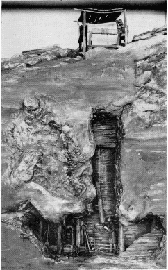
Figure 17.—Soft-ground tunneling. The support of walls and roof of mine shaft by simple timbering; 16th century. MHT model—3/4" scale. (Smithsonian photo 49260-J.)
In the left-hand portion of the model is the shaft sunk to begin operations; here also is shown the bucket hoist for removing the spoil. The V-type steam engine powering the hoist was designed by Brunel. At the right of the main model is an enlarged detail of the shield, actually an improved version built in 1835.
The work continued despite setbacks of every sort. The financial ones need no recounting here. Technically, although the shield principle proved workable, the support afforded was not infallible. Four or five times the river broke through the thin cover of silt and flooded the workings, despite the utmost caution in excavating. When this occurred, masses of clay, sandbags, and mats were dumped over the opening in the riverbed to seal it, and the tunnel pumped out. I. K. Brunel acted as superintendent and nearly lost his life on a number of occasions. After several suspensions of work resulting from withdrawal or exhaustion of support, one lasting seven years, the work was completed in 1843.
Despite the fact that Brunel had, for the first time, demonstrated a practical method for tunneling in firm and water-bearing ground, the enormous cost of the work and the almost overwhelming problems encountered had a discouraging effect rather than otherwise. Not for another quarter of a century was a similar project undertaken.
The Thames Tunnel was used for foot and light highway traffic until about 1870 when it was incorporated into the London Underground railway system, which it continues to serve today. The roofed-over top sections of the two shafts may still be seen from the river.
A number of contemporary popular accounts of the tunnel exist, but one of the most thorough and interesting expositions on a single tunnel work of any period is Henry Law’s A Memoir of the Thames Tunnel, published in 1845-1846 by John Weale. Law, an eminent civil engineer, covers the work in incredible detail from its inception until the major suspension in late 1828 when slightly more than half completed. The most valuable aspect of his record is a series of plates of engineering drawings of the shield and its components, which, so far as is known, exist nowhere else. These formed the basis of the enlarged section of the shield, shown to the right of the model of the tunnel itself. A vertical section through the shield is reproduced here from Law for comparison with the model (figs. 21 and 23).
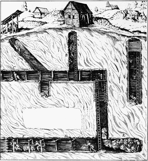
Figure 18.—Soft-ground tunneling. The model of a 16th century mine in the Museum of History and Technology was constructed from illustrations in such works as G. E. von Löhneyss' Bericht vom Bergwerck, 1690, as well as the better known ones from De re Metallica.
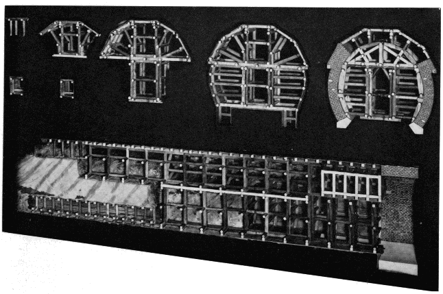
Figure 19.—The successive stages in the enlargement of a mid-19th century railroad tunnel, using the Austrian system of timbering. MHT model.
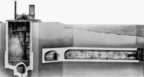
Figure 20.—M. I. Brunel's Thames Tunnel, 1825-1843, the first driven beneath a body of water. MHT model—1/4" scale. (Smithsonian photo 49260-F.)
THE TOWER SUBWAY
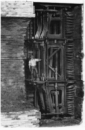
Figure 21.—Enlarged detail of Brunel's tunneling shield, vertical section. The first two and part of the third of the twelve frames are shown. To the left is the tunnel's completed brick lining and to the right, the individual breasting boards and screws for supporting the face. The propelling screws are seen at top and bottom, bearing against the lining. Three miners worked in each frame, one above the other. MHT model—3/4" scale. (Smithsonian photo 49260-G.)
Various inventors attempted to improve upon the Brunel shield, aware of the fundamental soundness of the shield principle. Almost all bypassed the rectangular sectional construction used in the Thames Tunnel, and took as a starting point a sectional shield of circular cross section, advanced by Brunel in his original patent of 1818. James Henry Greathead (1844-1896), rightfully called the father of modern subaqueous tunneling, surmised in later years that Brunel had chosen a rectangular configuration for actual use, as one better adapted to the sectional type of shield. The English civil engineer, Peter W. Barlow, in 1864 and 1868 patented a circular shield, of one piece, which was the basis of one used by him in constructing a small subway of 1350 feet beneath the Thames in 1869, the first work to follow the lead of Brunel. Greathead, acting as Barlow’s contractor, was the designer of the shield actually used in the work, but it was obviously inspired by Barlow’s patents.
The reduction of the multiplicity of parts in the Brunel shield to a single rigid unit was of immense advantage and an advance perhaps equal to the shield concept of tunneling itself. The Barlow-Greathead shield was like the cap of a telescope with a sharpened circular ring on the front to assist in penetrating the ground. The diaphragm functioned, as did Brunel’s breasting boards, to resist the longitudinal earth pressure of the face, and the cylindrical portion behind the diaphragm bore the radial pressure of roof and walls. Here also for the first time, a permanent lining formed of cast-iron segments was used, a second major advancement in soft-ground tunneling practice. Not only could the segments be placed and bolted together far more rapidly than masonry lining could be laid up, but unlike the green masonry, they could immediately bear the full force of the shield-propelling screws.
Barlow, capitalizing on Brunel’s error in burrowing so close to the riverbed, maintained an average cover of 30 feet over the tunnel, driving through a solid stratum of firm London clay which was virtually impervious to water. As the result of this, combined with the advantages of the solid shield and the rapidly placed iron lining, the work moved forward at a pace and with a facility in startling contrast to that of the Thames Tunnel, although in fairness it must be recalled that the face area was far less.
The clay was found sufficiently sound that it could be readily excavated without the support of the diaphragm, and normally three miners worked in front of the shield, digging out the clay and passing it back through a doorway in the plate. This could be closed in case of a sudden settlement or break in. Following excavation, the shield was advanced 18 inches into the excavated area by means of 6 screws, and a ring of lining segments 18 inches in length bolted to the previous ring under cover of the overlapping rear skirt of the shield. The small annular space left between the outside of the lining and the clay by the thickness and clearance of the skirt—about an inch—was filled with thin cement grout. The tunnel was advanced 18 inches during each 8-hour shift. The work continued around the clock, and the 900-foot river section was completed in only 14 weeks. [4] The entire work was completed almost without incident in just under a year, a remarkable performance for the world’s second subaqueous tunnel.
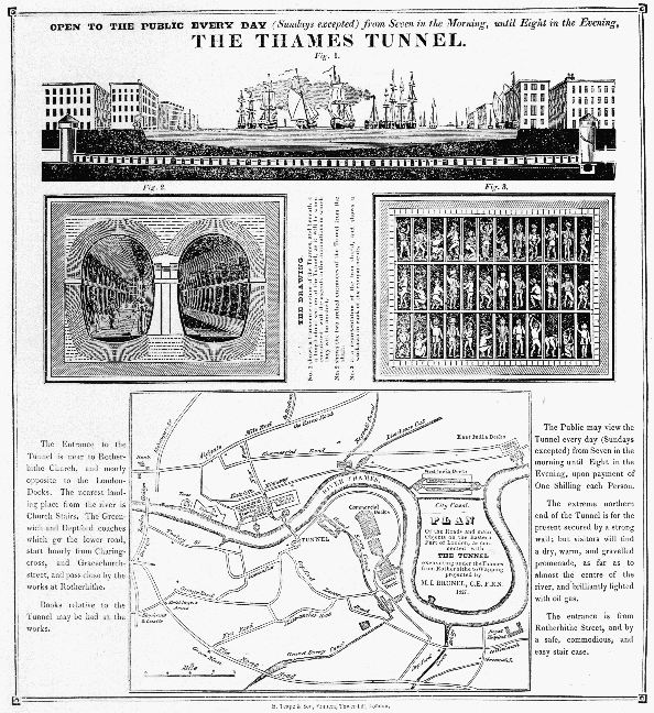
Figure 22.—Broadside published after commencement of work on the Thames Tunnel, 1827. (MHT collections.) Transcription of the text is presented in the Transcriber's Notes below.
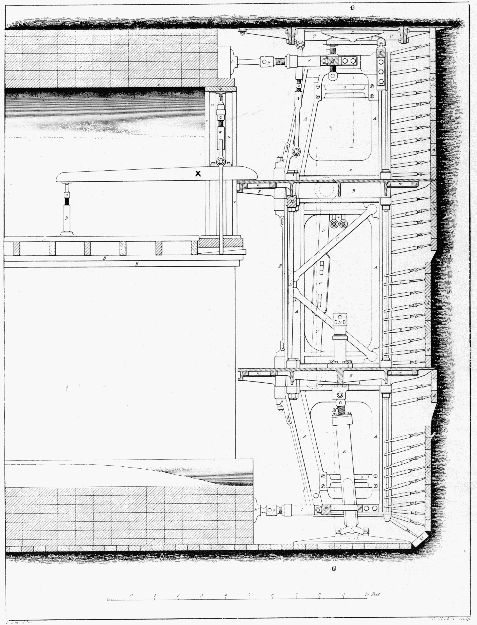
Figure 23.—Vertical section through Brunel's shield. The long lever, x, supported the wood centering for turning the masonry arches of the lining. (Law, A Memoir of the Thames Tunnel.)
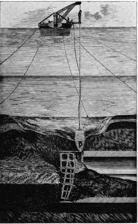
Figure 24.—Thames Tunnel. Section through riverbed and tunnel following one of the break-throughs of the river. Inspection of the damage with a diving bell. (Beamish, A Memoir of the Life of Sir Marc Isambard Brunel.)
The Tower Subway at first operated with cylindrical cars that nearly filled the 7-foot bore; the cars were drawn by cables powered by small steam engines in the shafts. This mode of power had previously been used in passenger service only on the Greenwich Street elevated railway in New York. Later the cars were abandoned as unprofitable and the tunnel turned into a footway (fig. 32). This small tunnel, the successful driving due entirely to Greathead’s skill, was the forerunner of the modern subaqueous tunnel. In it, two of the three elements essential to such work thereafter were first applied: the one-piece movable shield of circular section, and the segmental cast-iron lining.
The documentation of this work is far thinner than for the Thames Tunnel. The most accurate source of technical information is a brief historical account in Copperthwaite’s classic Tunnel Shields and the Use of Compressed Air in Subaqueous Works, published in 1906. Copperthwaite, a successful tunnel engineer, laments the fact that he was able to turn up no drawing or original data on this first shield of Greathead’s, but he presents a sketch of it prepared in the Greathead office in 1895, which is presumably a fair representation (fig. 33). The Tower Subway model was built on the basis of this and several woodcuts of the working area that appeared contemporaneously in the illustrated press. In this and the adjacent model of Beach’s Broadway Subway, the tunnel axis has been placed on an angle to the viewer, projecting the bore into the case so that the complete circle of the working face is included for a more suggestive effect. This was possible because of the short length of the work included.
Henry S. Drinker, also a tunnel engineer and author of the most comprehensive work on tunneling ever published, treats rock tunneling in exhaustive detail up to 1878. His notice of what he terms “submarine tunneling” is extremely brief. He does, however, draw a most interesting comparison between the first Thames Tunnel, built by Brunel, and the second, built by Greathead 26 years later:
FIRST THAMES TUNNEL SECOND THAMES TUNNEL (TOWER SUBWAY)
Brickwork lining, 38 feet wide by 221/2 feet high. Cast-iron lining of 8 feet outside diameter.
120-ton cast-iron shield, accommodating 36 miners. 21/2-ton, wrought-iron shield, accommodating at most 3 men.
Workings filled by irruption of river five times. “Water encountered at almost any time could have been gathered in a stable pail.”
Eighteen years elapsed between start and finish of work. Work completed in about eleven months.
Cost: $3,000,000. Cost: $100,000.
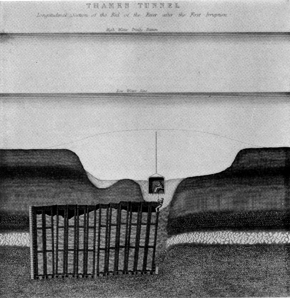
Figure 25.—Transverse section through shield, after inundation. Such disasters, as well as the inconsistency of the riverbed's composition, seriously disturbed the alignment of the shield's individual sections. (Law, A Memoir of the Thames Tunnel.)
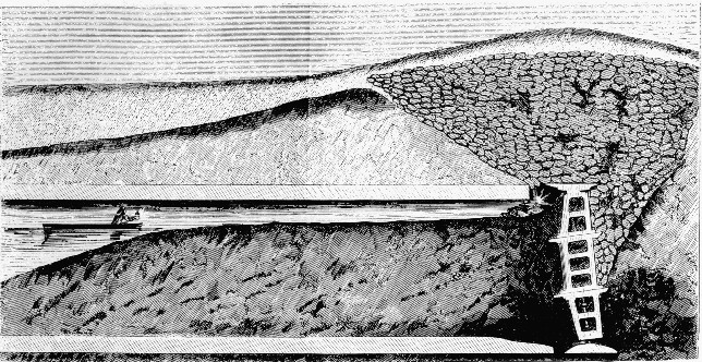
Figure 26.—Longitudinal section through Thames Tunnel after sandbagging to close a break in the riverbed. The tunnel is filled with silt and water. (Law, A Memoir of the Thames Tunnel.)
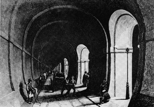
Figure 27.—Interior of the Thames Tunnel shortly after completion in 1843. (Photo courtesy of New York Public Library Picture Collection.)
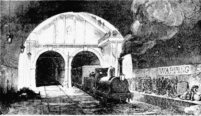
Figure 28.—Thames Tunnel in use by London Underground railway. (Illustrated London News, 1869?)
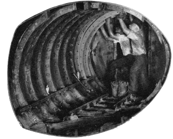
Figure 29.—Placing a segment of cast-iron lining in Greathead's Tower Subway, 1869. To the rear is the shield's diaphragm or bulkhead. MHT model—11/2" scale. (Smithsonian photo 49260-B.)
BEACH’S BROADWAY SUBWAY
Almost simultaneously with the construction of the Tower Subway, the first American shield tunnel was driven by Alfred Ely Beach (1826-1896). Beach, as editor of the Scientific American and inventor of, among other things, a successful typewriter as early as 1856, was well known and respected in technical circles. He was not a civil engineer, but had become concerned with New York’s pressing traffic problem (even then) and as a solution, developed plans for a rapid-transit subway to extend the length of Broadway. He invented a shield as an adjunct to this system, solely to permit driving of the tunnel without disturbing the overlying streets.
An active patent attorney as well, Beach must certainly have known of and studied the existing patents for tunneling shields, which were, without exception, British. In certain aspects his shield resembled the one patented by Barlow in 1864, but never built. However, work on the Beach tunnel started in 1869, so close in time to that on the Tower Subway, that it is unlikely that there was any influence from that source. Beach had himself patented a shield, in June 1869, a two-piece, sectional design that bore no resemblance to the one used. His subway plan had been first introduced at the 1867 fair of the American Institute in the form of a short plywood tube through which a small, close-fitting car was blown by a fan. The car carried 12 passengers. Sensing opposition to the subway scheme from Tammany, in 1868 Beach obtained a charter to place a small tube beneath Broadway for transporting mail and small packages pneumatically, a plan he advocated independently of the passenger subway.
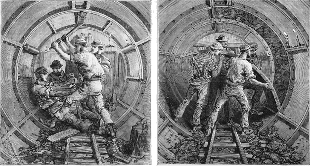
ADVANCING THE SHIELD. FITTING THE CASTINGS.
Figure 30.—Contemporary illustrations of Tower Subway works used as basis of the model in the Museum of History and Technology. (Illustrated London News, 1869.)
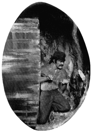
Figure 31.—Excavation in front of shield, Tower Subway. This was possible because of the stiffness of the clay encountered. MHT model—front of model shown in fig. 29. (Smithsonian photo 49260-A.)
Under this thin pretense of legal authorization, the sub-rosa excavation began from the basement of a clothing store on Warren Street near Broadway. The 8-foot-diameter tunnel ran eastward a short distance, made a 90-degree turn, and thence southward under Broadway to stop a block away under the south side of Murray Street. The total distance was about 312 feet. Work was carried on at night in total secrecy, the actual tunneling taking 58 nights. At the Warren Street terminal, a waiting room was excavated and a large Roots blower installed for propulsion of the single passenger car. The plan was similar to that used with the model in 1867: the cylindrical car fitted the circular tunnel with only slight circumferential clearance. The blower created a plenum within the waiting room and tunnel area behind the car of about 0.25 pounds per square inch, resulting in a thrust on the car of almost a ton, not accounting for blowby. The car was thus blown along its course, and was returned by reversing the blower’s suction and discharge ducts to produce an equivalent vacuum within the tunnel.
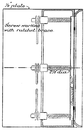
Figure 33.—Vertical section through the Greathead shield used at the Tower Subway, 1869. The first one-piece shield of circular section. (Copperthwaite, Tunnel Shields and the Use of Compressed Air in Subaqueous Works.)
The system opened in February of 1870 and remained in operation for about a year. Beach was ultimately subdued by the hostile influences of Boss Tweed, and the project was completely abandoned. Within a very few more years the first commercially operated elevated line was built, but the subway did not achieve legitimate status in New York until the opening of the Interborough line in 1904. Ironically, its route traversed Broadway for almost the length of the island.
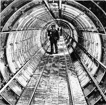
Figure 32.—Interior of completed Tower Subway. (Thornbury, Old and New London, 1887, vol. 1, p. 126.)
The Beach shield operated with perfect success in this brief trial, although the loose sandy soil encountered was admittedly not a severe test of its qualities. No diaphragm was used; instead a series of 8 horizontal shelves with sharpened leading edges extended across the front opening of the shield. The outstanding feature of the machine was the substitution for the propelling screws used by Brunel and Greathead of 18 hydraulic rams, set around its circumference. These were fed by a single hand-operated pump, seen in the center of figure 34. By this means the course of the shield’s forward movement could be controlled with a convenience and precision not attainable with screws. Vertical and horizontal deflection was achieved by throttling the supply of water to certain of the rams, which could be individually controlled, causing greater pressure on one portion of the shield than another. This system has not changed in the ensuing time, except, of course, in the substitution of mechanically produced hydraulic pressure for hand.
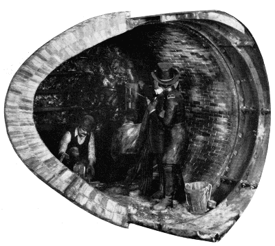
Figure 34.—Beach's Broadway Subway. Advancing the shield by hydraulic rams, 1869. MHT model—11/2" scale. (Smithsonian photo 49260-E.)
Unlike the driving of the Tower Subway, no excavation was done in front of the shield. Rather, the shield was forced by the rams into the soil for the length of their stroke, the material which entered being supported by the shelves. This was removed from the shelves and hauled off. The ram plungers then were withdrawn and a 16-inch length of the permanent lining built up within the shelter of the shield’s tail ring. Against this, the rams bore for the next advance. Masonry lining was used in the straight section; cast-iron in the curved. The juncture is shown in the model.
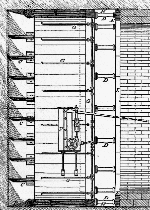
Figure 35.—Vertical section through the Beach shield used on the Broadway Subway, showing the horizontal shelves (C), iron cutting ring (B), hydraulic rams (D), hydraulic pump (F), and rear protective skirt (H). (Scientific American, March 5, 1870.)
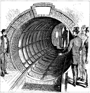
Figure 36.—Interior of Beach Subway showing iron lining on curved section and the pneumatically powered passenger car. View from waiting room. (Scientific American, March 5, 1870.)
Enlarged versions of the Beach shield were used in a few tunnels in the Midwest in the early 1870’s, but from then until 1886 the shield method, for no clear reason, again entered a period of disuse finding no application on either side of the Atlantic despite its virtually unqualified proof at the hands of Greathead and Beach. Little precise information remains on this work. The Beach system of pneumatic transit is described fully in a well-illustrated booklet published by him in January 1868, in which the American Institute model is shown, and many projected systems of pneumatic propulsion as well as of subterranean and subaqueous tunneling described. Beach again (presumably) is author of the sole contemporary account of the Broadway Subway, which appeared in Scientific American following its opening early in 1870. Included are good views of the tunnel and car, of the shield in operation, and, most important, a vertical sectional view through the shield (fig. 35).
It is interesting to note that optical surveys for maintenance of the course apparently were not used. The article illustrated and described the driving each night of a jointed iron rod up through the tunnel roof to the street, twenty or so feet above, for “testing the position.”
THE FIRST HUDSON RIVER TUNNEL
Despite the ultimate success of Brunel’s Thames Tunnel in 1843, the shield in that case afforded only moderately reliable protection because of the fluidity of the soil driven through, and its tendency to enter the works through the smallest opening in the shield’s defense. An English doctor who had made physiological studies of the effects on workmen of the high air pressure within diving bells is said to have recommended to Brunel in 1828 that he introduce an atmosphere of compressed air into the tunnel to exclude the water and support the work face.
This plan was first formally described by Sir Thomas Cochrane (1775-1860) in a British patent of 1830. Conscious of Brunel’s problems, he proposed a system of shaft sinking, mining, and tunneling in water-bearing materials by filling the excavated area with air sufficiently above atmospheric pressure to prevent the water from entering and to support the earth. In this, and his description of air locks for passage of men and materials between the atmosphere and the pressurized area, Cochrane fully outlined the essential features of pneumatic excavation as developed since.
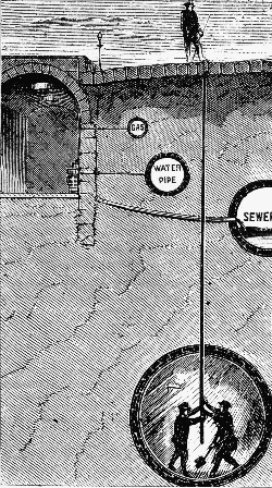
Figure 37.—The giant Roots lobe-type blower used for propelling the car. Figure 38.—Testing alignment of the Broadway Subway at night by driving a jointed rod up to street level. (Scientific American, March 5, 1870.)
In 1839, a French engineer first used the system in sinking a mine shaft through a watery stratum. From then on, the sinking of shafts, and somewhat later the construction of bridge pier foundations, by the pneumatic method became almost commonplace engineering practice in Europe and America. Not until 1879 however, was the system tried in tunneling work, and then, as with the shield ten years earlier, almost simultaneously here and abroad. The first application was in a small river tunnel in Antwerp, only 5 feet in height. This project was successfully completed relying on compressed air alone to support the earth, no shield being used. The importance of the work cannot be considered great due to its lack of scope.
In 1871 Dewitt C. Haskin (1822-1900), a west coast mine and railroad builder, became interested in the pneumatic caissons then being used to found the river piers of Eads’ Mississippi River bridge at St. Louis. In apparent total ignorance of the Cochrane patent, he evolved a similar system for tunneling water-bearing media, and in 1873 proposed construction of a tunnel through the silt beneath the Hudson to provide rail connection between New Jersey and New York City.
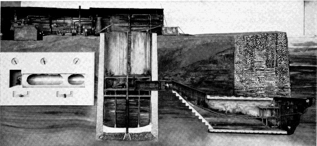
Figure 39.—Haskin's pneumatically driven tunnel under the Hudson River, 1880. In the engine room at top left was the machinery for hoisting, generating electricity for lighting, and air compressing. The air lock is seen in the wall of the brick shaft. MHT model—0.3" scale. (Smithsonian photo 49260.)
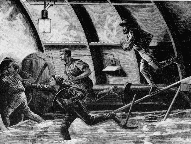
Figure 40.—Artist's conception of miners escaping into the air lock during the blowout in Haskin's tunnel.
It would be difficult to imagine a site more in need of such communication. All lines from the south terminated along the west shore of the river and the immense traffic—cars, freight and passengers—was carried across to Manhattan Island by ferry and barge with staggering inconvenience and at enormous cost. A bridge would have been, and still is, almost out of the question due not only to the width of the crossing, but to the flatness of both banks. To provide sufficient navigational clearance (without a drawspan), impracticably long approaches would have been necessary to obtain a permissibly gentle grade.
Haskin formed a tunneling company and began work with the sinking of a shaft in Hoboken on the New Jersey side. In a month it was halted because of an injunction by, curiously, the D L & W Railroad, who feared for their vast investment in terminal and marine facilities. Not until November of 1879 was the injunction lifted and work again commenced. The shaft was completed and an air lock located in one wall from which the tunnel proper was to be carried forward. It was Haskin’s plan to use no shield, relying solely on the pressure of compressed air to maintain the work faces and prevent the entry of water. The air was admitted in late December, and the first large-scale pneumatic tunneling operation launched. A single 26-foot, double-track bore was at first undertaken, but a work face of such diameter proved unmanageable and two oval tubes 18 feet high by 16 feet wide were substituted, each to carry a single track. Work went forward with reasonable facility, considering the lack of precedent. A temporary entrance was formed of sheet-iron rings from the air lock down to the tunnel grade, at which point the permanent work of the north tube was started. Immediately behind the excavation at the face, a lining of thin wrought-iron plates was built up, to provide form for the 2-foot, permanent brick lining that followed. The three stages are shown in the model in about their proper relationship of progress. The work is shown passing beneath an old timber-crib bulkhead, used for stabilizing the shoreline.
The silt of the riverbed was about the consistency of putty and under good conditions formed a secure barrier between the excavation and the river above. It was easily excavated, and for removal was mixed with water and blown out through a pipe into the shaft by the higher pressure in the tunnel. About half was left in the bore for removal later. The basic scheme was workable, but in operation an extreme precision was required in regulating the air pressure in the work area. [5] It was soon found that there existed an 11-psi difference between the pressure of water on the top and the bottom of the working face, due to the 22-foot height of the unlined opening. Thus, it was impossible to maintain perfect pneumatic balance of the external pressure over the entire face. It was necessary to strike an average with the result that some water entered at the bottom of the face where the water pressure was greatest, and some air leaked out at the top where the water pressure was below the air pressure. Constant attention was essential: several men did nothing but watch the behavior of the leaks and adjusted the pressure as the ground density changed with advance. Air was supplied by several steam-driven compressors at the surface.
The air lock permitted passage back and forth of men and supplies between the atmosphere and the work area, without disturbing the pressure differential. This principle is demonstrated by an animated model set into the main model, to the left of the shaft (fig. 39). The variation of pressure within the lock chamber to match the atmosphere or the pressurized area, depending on the direction of passage, is clearly shown by simplified valves and gauges, and by the use of light in varying color density. In the Haskin tunnel, 5 to 10 minutes were taken to pass the miners through the lock so as to avoid too abrupt a physiological change.
Despite caution, a blowout occurred in July 1880 due to air leakage not at the face, but around the temporary entrance. One door of the air lock jammed and twenty men drowned, resulting in an inquiry which brought forth much of the distrust with which Haskin was regarded by the engineering profession. His ability and qualifications were subjected to the bitterest attack in and by the technical press. There is some indication that, although the project began with a staff of competent engineers, they were alienated by Haskin in the course of work and at least one withdrew. Haskin’s remarks in his own defense indicate that some of the denunciation was undoubtedly justified. And yet, despite this reaction, the fundamental merit of the pneumatic tunneling method had been demonstrated by Haskin and was immediately recognized and freely acknowledged. It was apparent at the same time, however, that air by itself did not provide a sufficiently reliable support for large-area tunnel works in unstable ground, and this remains the only major subaqueous tunnel work driven with air alone.
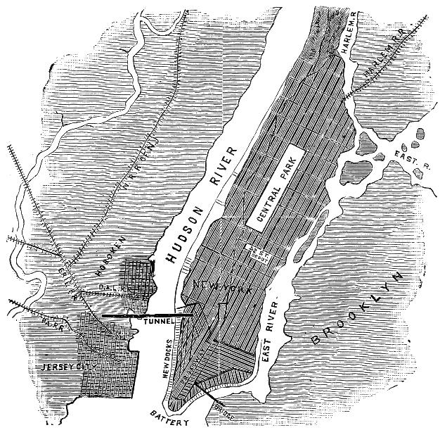
Figure 41.—Location of Hudson River Tunnel. (Leslie's Weekly, 1879.)
After the accident, work continued under Haskin until 1882 when funds ran out. About 1600 feet of the north tube and 600 feet of the south tube had been completed. Greathead resumed operations with a shield for a British company in 1889, but exhaustion of funds again caused stoppage in 1891. The tunnel was finally completed in 1904, and is now in use as part of the Hudson and Manhattan rapid-transit system, never providing the sought-after rail link. A splendid document of the Haskin portion of the work is S. D. V. Burr’s Tunneling Under the Hudson River published in 1885. It is based entirely upon firsthand material and contains drawings of most of the work, including the auxiliary apparatus. It is interesting to note that electric illumination (arc, not incandescent, lights) and telephones were used, unquestionably the first employment of either in tunnel work.
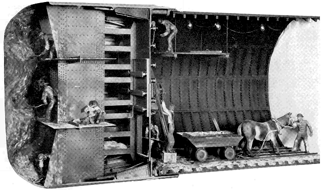
Figure 42.—St. Clair Tunnel. View of front of shield showing method of excavation in firm strata. Incandescent electric illumination was used. 1889-90. MHT model—1" scale. (Smithsonian photo 49260-D.)
THE ST. CLAIR TUNNEL
The final model of the soft-ground series reflects, as did the Hoosac Tunnel model for hard-rock tunneling, final emergence into the modern period. Although the St. Clair Tunnel was completed over 70 years ago, it typifies in its method of construction, the basic procedures of subaqueous work in the present day. The Thames Tunnel of Brunel, and Haskin’s efforts beneath the Hudson, had clearly shown that by themselves, both the shield and pneumatic systems of driving through fluid ground were defective in practice for tunnels of large area. Note that the earliest successful works by each method had been of very small area, so that the influence of adverse conditions was greatly diminished.
The first man to perceive and seize upon the benefits to be gained by combining the two systems was, most fittingly, Greathead. Although he had projected the technique earlier, in driving the underground City and South London Railway in 1886, he brought together for the first time the three fundamental elements essential for the practical tunneling of soft, water-bearing ground: compressed-air support of the work during construction, the movable shield, and cast-iron, permanent lining. The marriage was a happy one indeed; the limitations of each system were almost perfectly overcome by the qualities of the others.
The conditions prevailing in 1882 at the Sarnia, Ontario, terminal of the Grand Trunk Railway, both operational and physical, were almost precisely the same as those which inspired the undertaking of the Hudson River Tunnel. The heavy traffic at this vital U.S.—Canada rail interchange was ferried inconveniently across the wide St. Clair River, and the bank and river conditions precluded construction of a bridge. A tunnel was projected by the railway in that year, the time when Haskin’s tribulations were at their height. Perhaps because of this lack of precedent for a work of such size, nothing was done immediately. In 1884 the railway organized a tunnel company; in 1886 test borings were made in the riverbed and small exploratory drifts were started across from both banks by normal methods of mine timbering. The natural gas, quicksand, and water encountered soon stopped the work.
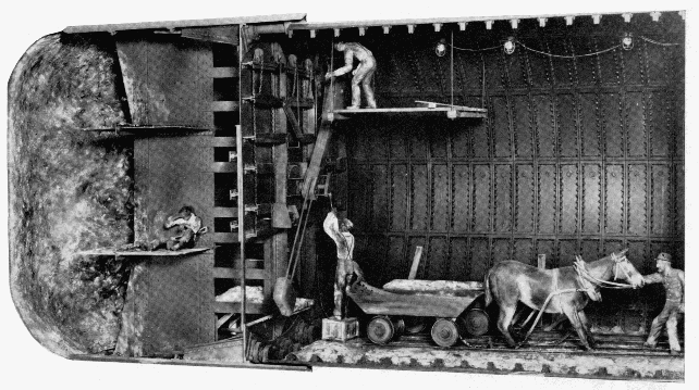
Figure 43.—Rear view of St. Clair shield showing the erector arm placing a cast-iron lining segment. The three motions of the arm—axial, radial, and rotational, were manually powered. (Smithsonian photo 49260-C.)
It was at this time that the railway’s president visited Greathead’s City and South London workings. The obvious answer to the St. Clair problem lay in the successful conduct of this subway. Joseph Hobson, chief engineer of the Grand Trunk and of the tunnel project, in designing a shield, is said to have searched for drawings of the shields used in the Broadway and Tower Subways of 1868-9, but unable to locate any, he relied to a limited extent on the small drawings of those in Drinker’s volume. There is no explanation as to why he did not have drawings of the City and South London shield at that moment in use, unless one considers the rather unlikely possibility that Greathead maintained its design in secrecy.
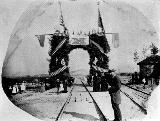
Figure 44.—Opening of the St. Clair Tunnel, 1891. (Photo courtesy of Detroit Library, Burton Historical Collection.)
The Hobson shield followed Greathead’s as closely as any other, in having a diaphragm with closable doors, but a modification of Beach’s sharpened horizontal shelves was also used. However, these functioned more as working platforms than supports for the earth. The machine was 211/2 feet in diameter, an unprecedented size and almost twice that of Greathead’s current one. It was driven by 24 hydraulic rams. Throughout the entire preliminary consideration of the project there was a marked sense of caution that amounted to what seems an almost total lack of confidence in success. Commencement of the work from vertical shafts was planned so that if the tunnel itself failed, no expenditure would have been made for approach work. In April 1888, the shafts were started near both riverbanks, but before reaching proper depth the almost fluid clay and silt flowed up faster than it could be excavated and this plan was abandoned. After this second inauspicious start, long open approach cuts were made and the work finally began. The portals were established in the cuts, several thousand feet back from each bank and there the tunneling itself began. The portions under the shore were driven without air. When the banks were reached, brick bulkheads containing air locks were built across the opening and the section beneath the river, about 3,710 feet long, driven under air pressure of 10 to 28 pounds above atmosphere. For most of the way, the clay was firm and there was little air leakage. It was found that horses could not survive in the compressed air, and so mules were used under the river.
In the firm clay, excavation was carried on several feet in front of the shield, as shown in the model (fig. 42). About twelve miners worked at the face. However, in certain strata the clay encountered was so fluid that the shield could be simply driven forward by the rams, causing the muck to flow in at the door openings without excavation. After each advance, the rams were retracted and a ring of iron lining segments built up, as in the Tower Subway. Here, for the first time, an “erector arm” was used for placing the segments, which weighed about half a ton. In all respects, the work advanced with wonderful facility and lack of operational difficulty. Considering the large area, no subaqueous tunnel had ever been driven with such speed. The average monthly progress for the American and Canadian headings totaled 455 feet, and at top efficiency 10 rings or a length of 15.3 feet could be set in a 24-hour day in each heading. The 6,000 feet of tunnel was driven in just a year; the two shields met vis-a-vis in August of 1890.
The transition was complete. The work had been closely followed by the technical journals and the reports of its successful accomplishment thus were brought to the attention of the entire civil engineering profession. As the first major subaqueous tunnel completed in America and the first in the world of a size able to accommodate full-scale rail traffic, the St. Clair Tunnel served to dispel the doubts surrounding such work, and established the pattern for a mode of tunneling which has since changed only in matters of detail.
Of the eight models, only this one was built under the positive guidance of original documents. In the possession of the Canadian National Railways are drawings not only of all elements of the shield and lining, but of much of the auxiliary apparatus used in construction. Such materials rarely survive, and do so in this case only because of the foresight of the railway which, to avoid paying a high profit margin to a private contractor as compensation for the risk and uncertainty involved, carried the contract itself and, therefore, preserved all original drawing records.
While the engineering of tunnels has been comprehensively treated in this paper from the historical standpoint, it is well to still reflect that the advances made in tunneling have not perceptibly removed the elements of uncertainty but have only provided more positive and effective means of countering their forces. Still to be faced are the surprises of hidden streams, geologic faults, shifts of strata, unstable materials, and areas of extreme pressure and temperature.
BIBLIOGRAPHY
Agricola, Georgius. De re Metallica. [English transl. H. C. and L. H. Hoover (The Mining Magazine, London, 1912).] Basel: Froben, 1556.
Beach, Alfred Ely. The pneumatic dispatch. New York: The American News Company, 1868.
Beamish, Richard. A memoir of the life of Sir Marc Isambard Brunel. London: Longmans, Green, Longmans and Roberts, 1862.
Burr, S. D. V. Tunneling under the Hudson River. New York: John Wiley and Sons, 1885.
Copperthwaite, William Charles. Tunnel shields and the use of compressed air in subaqueous works. New York: D. Van Nostrand Company, 1906.
Drinker, Henry Sturgess. Tunneling, explosive compounds and rock drills. New York: John Wiley and Sons, 1878.
Latrobe, Benjamin H. Report on the Hoosac Tunnel (Baltimore, October 1, 1862). Pp. 125-139, app. 2, in Report of the commissioners upon the Troy and Greenfield Railroad and Hoosac Tunnel. Boston, 1863.
Law, Henry. A memoir of the Thames Tunnel. Weale’s Quarterly Papers on Engineering (London, 1845-46), vol. 3, pp. 1-25 and vol. 5, pp. 1-86.
The pneumatic tunnel under Broadway, N.Y. Scientific American (March 5, 1870), pp. 154-156.
Report of the commissioners upon the Troy and Greenfield Railroad and Hoosac Tunnel to his excellency the governor and the honorable the executive council of the state of Massachusetts, February 28, 1863. Boston, 1863.
Storrow, Charles S. Report on European tunnels (Boston, November 28, 1862). Pp. 5-122, app. 1, in Report of the commissioners upon the Troy and Greenfield Railroad and Hoosac Tunnel…. Boston, 1863.
The St. Clair Tunnel. Engineering News (in series running October 4 to December 27, 1890).
FOOTNOTES
Paper 41 - Transcriber’s Note
All obvious typographical errors corrected. Formatting inconsistancies and spelling were standardized. Paragraphs split by illustrations were rejoined.
Transcription of the text in Figure 22. The text was transcribed with a slight modification to the figure description portion.
OPEN TO THE PUBLIC EVERY DAY (Sundays excepted) from Seven in the Morning, until Eight in the Evening,
THE THAMES TUNNEL.
Fig. 1 shows a transverse section of the Thames, and beneath it a longitudinal section of the Tunnel, as it will be when completed; with the ascents in the inclinations in which they will be finished.
Fig. 2 shows the two arched entrances of the Tunnel from the shaft.
Fig. 3 is a representation of the iron shield, and shows a workman in each of the compartments.
The Entrance to the Tunnel is near to Rotherhithe Church, and nearly opposite to the London-Docks. The nearest landing place from the river is Church Stairs. The Greenwich and Deptford coaches which go the lower road, start hourly from Charing-cross, and Gracechurch-street, and pass close by the works at Rotherhithe.
Books relative to the Tunnel may be had at the works.
The Public may view the Tunnel every day (Sundays excepted) from Seven in the morning until Eight in the Evening, upon payment of One Shilling each Person.
The extreme northern end of the Tunnel is for the present secured by a strong wall; but visitors will find a dry, warm, and gravelled promenade, as far as to almost the centre of the river, and brilliantly lighted with oil gas.
The entrance is from Rotherhithe Street, and by a safe, commodious, and easy stair case.
H. Teape & Son, Printers, Tower-hill, London.
Contributions from The Museum of History and Technology. Paper 42 The “Pioneer”: Light Passenger Locomotive of 1851 In the Museum of History and Technology
John H. White
THE CUMBERLAND VALLEY RAILROAD 244
SERVICE HISTORY OF THE “PIONEER” 249
MECHANICAL DESCRIPTION OF THE “PIONEER” 251
INDEX
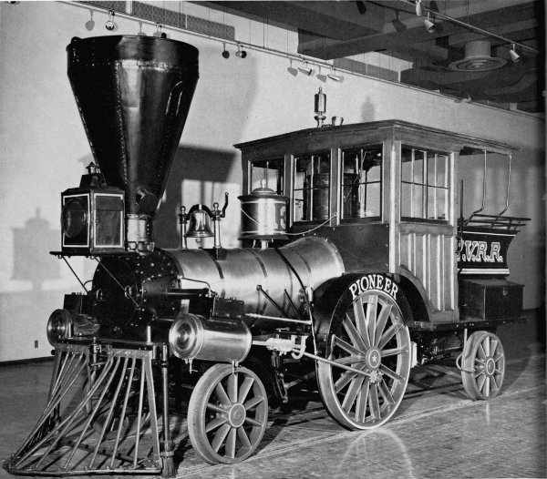
Figure 1.—The “Pioneer,” built in 1851, shown here as renovated and exhibited in the Museum of History and Technology, 1964. In 1960 the locomotive was given to the Smithsonian Institution by the Pennsylvania Railroad through John S. Fair, Jr. (Smithsonian photo 63344B.)
John H. White
The “PIONEER”: LIGHT PASSENGER LOCOMOTIVE of 1851 In the Museum of History and Technology
In the mid-nineteenth century there was a renewed interest in the light, single-axle locomotives which were proving so very successful for passenger traffic. These engines were built in limited number by nearly every well-known maker, and among the few remaining is the 6-wheel “Pioneer,” on display in the Museum of History and Technology, Smithsonian Institution. This locomotive is a true representation of a light passenger locomotive of 1851 and a historic relic of the mid-nineteenth century.
The Author: John H. White is associate curator of transportation in the Smithsonian Institution’s Museum of History and Technology.
The “Pioneer” is an unusual locomotive and on first inspection would seem to be imperfect for service on an American railroad of the 1850’s. This locomotive has only one pair of driving wheels and no truck, an arrangement which marks it as very different from the highly successful standard 8-wheel engine of this period. All six wheels of the Pioneer are rigidly attached to the frame. It is only half the size of an 8-wheel engine of 1851 and about the same size of the 4—2—0 so common in this country some 20 years earlier. Its general arrangement is that of the rigid English locomotive which had, years earlier, proven unsuitable for use on U.S. railroads.
These objections are more apparent than real, for the Pioneer, and other engines of the same design, proved eminently successful when used in the service for which they were built, that of light passenger traffic. The Pioneer’s rigid wheelbase is no problem, for when it is compared to that of an 8-wheel engine it is found to be about four feet less; and its small size is no problem when we realize it was not intended for heavy service. Figure 2, a diagram, is a comparison of the Pioneer and a standard 8-wheel locomotive.
Since the service life of the Pioneer was spent on the Cumberland Valley Railroad, a brief account of that line is necessary to an understanding of the service history of this locomotive.
Exhibits of the “Pioneer”
The Pioneer has been a historic relic since 1901. In the fall of that year minor repairs were made to the locomotive so that it might be used in the sesquicentennial celebration at Carlisle, Pennsylvania. On October 22, 1901, the engine was ready for service, but as it neared Carlisle a copper flue burst. The fire was extinguished and the Pioneer was pushed into town by another engine. In the twentieth century, the Pioneer was displayed at the Louisiana Purchase Exposition, St. Louis, Missouri, in 1904, and at the Wheeling, West Virginia, semicentennial in 1913. In 1927 it joined many other historic locomotives at the Baltimore and Ohio Railroad’s “Fair of the Iron Horse” which commemorated the first one hundred years of that company. From about 1913 to 1925 the Pioneer also appeared a number of times at the Apple-blossom Festival at Winchester, Virginia. In 1933-1934 it was displayed at the World’s Fair in Chicago, and in 1948 at the Railroad Fair in the same city. Between 1934 and March 1947 it was exhibited at the Franklin Institute, Philadelphia, Pennsylvania.
The Cumberland Valley Railroad
The Cumberland Valley Railroad (C.V.R.R.) was chartered on April 2, 1831, to connect the Susquehanna and Potomac Rivers by a railroad through the Cumberland Valley in south-central Pennsylvania. The Cumberland Valley, with its rich farmland and iron-ore deposits, was a natural north-south route long used as a portage between these two rivers. Construction began in 1836, and because of the level valley some 52 miles of line was completed between Harrisburg and Chambersburg by November 16, 1837. In 1860, by way of the Franklin Railroad, the line extended to Hagerstown, Maryland. It was not until 1871 that the Cumberland Valley Railroad reached its projected southern terminus, the Potomac River, by extending to Powells Bend, Maryland. Winchester, Virginia, was entered in 1890 giving the Cumberland Valley Railroad about 165 miles of line. The railroad which had become associated with the Pennsylvania Railroad in 1859, was merged with that company in 1919.
By 1849 the Cumberland Valley Railroad was in poor condition; the strap-rail track was worn out and new locomotives were needed. Captain Daniel Tyler was hired to supervise rebuilding the line with T-rail, and easy grades and curves. Tyler recommended that a young friend of his, Alba F. Smith, be put in charge of modernizing and acquiring new equipment. Smith recommended to the railroad’s Board of Managers on June 25, 1851, that “much lighter engines than those now in use may be substituted for the passenger transportation and thereby effect a great saving both in point of fuel and road repairs….”[1] Smith may well have gone on to explain that the road was operating 3- and 4-car passenger trains with a locomotive weighing about 20 tons; the total weight was about 75 tons, equalling the uneconomical deadweight of 1200 pounds per passenger. Since speed was not an important consideration (30 mph being a good average), the use of lighter engines would improve the deadweight-to-passenger ratio and would not result in a slower schedule.
The Board of Managers agreed with Smith’s recommendations and instructed him “… to examine the two locomotives lately built by Mr. Wilmarth and now in the [protection?] of Captain Tyler at Norwich and if in his judgment they are adequate to our wants … have them forwarded to the road.” [2] Smith inspected the locomotives not long after this resolution was passed, for they were on the road by the time he made the following report [3] to the Board on September 24, 1851:
In accordance with a resolution passed at the last meeting of your body relative to the small engines built by Mr. Wilmarth I proceeded to Norwich to make trial of their capacity—fitness or suitability to the Passenger transportation of our Road—and after as thorough a trial as circumstances would admit (being on another Road than our own) I became satisfied that with some necessary improvements which would not be expensive (and are now being made at our shop) the engines would do the business of our Road not only in a manner satisfactory in point of speed and certainty but with greater ultimate economy in Expenses than has before been practised in this Country.
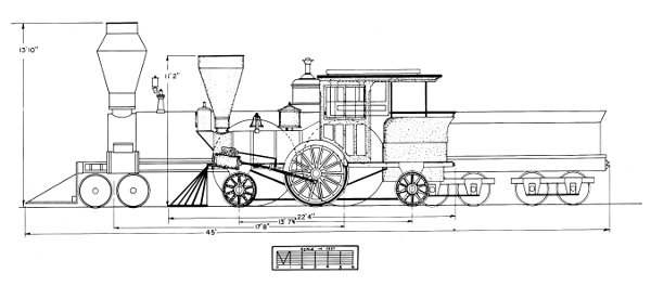
Figure 2.—Diagram comparing the Pioneer (shaded drawing) with the Columbia, a standard 8-wheel engine of 1851. (Drawing by J. H. White.)
Columbia Hudson River Railroad Lowell Machine Shop, 1852 Wt. 271/2 tons (engine only) Cyl. 161/2 x 22 inches Wheel diam. 84 inches Pioneer Cumberland Valley Railroad Seth Wilmarth, 1851 121/2 tons 81/2 x 14 inches 54 inches
After making the above trial of the Engines—I stated to your Hon. President the result of the trial—with my opinion of their Capacity to carry our passenger trains at the speed required which was decidedly in favor of the ability of the Engines. He accordingly agreed that the Engines should at once be forwarded to the Road in compliance with the Resolution of your Board. I immediately ordered the Engines shipped at the most favorable rates. They came to our Road safely in the Condition in which they were shipped. One of the Engines has been placed on the Road and I believe performed in such a manner as to convince all who are able to judge of this ability to perform—although the maximum duty of the Engines was not performed on account of some original defects which are now being remedied as I before stated.
Within ten days the Engine will be able to run regularly with a train on the Road where in shall be enabled to judge correctly of their merits.
An accident occurred during the trial of the Small Engine at Norwich which caused a damage of about $300 in which condition the Engine came here and is now being repaired—the cost of which will be presented to your Board hereafter. As to the fault or blame of parties connected with the accident as also the question of responsibility for Repairs are questions for your disposal. I therefore leave the matter until further called upon.
The Expenses necessarily incurred by the trial of the Engines and also the Expenses of transporting the same are not included in the Statement herewith presented, the whole amount of which will not probably exceed $400.00.
These two locomotives became the Cumberland Valley Railroad’s Pioneer (number 13) and Jenny Lind (number 14). While Smith notes that one of the engines was damaged during the inspection trials, Joseph Winters, an employee of the Cumberland Valley who claimed he was accompanying the engine enroute to Chambersburg at the time of their delivery, later recalled that both engines were damaged in transit.[4] According to Winters a train ran into the rear of the Jenny Lind, damaging both it and the Pioneer, the accident occurring near Middletown, Pennsylvania. The Jenny Lind was repaired at Harrisburg but the Pioneer, less seriously damaged, was taken for repairs to the main shops of the Cumberland Valley road at Chambersburg.
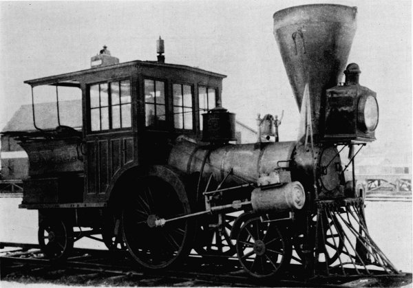
Figure 3.—“Pioneer,” about 1901, showing the sandbox and large headlamp. Note the lamp on the cab roof, now used as the headlight. (Smithsonian photo 49272.)
While there seems little question that these locomotives were not built as a direct order for the Cumberland Valley Railroad, an article[5] appearing in the Railroad Advocate in 1855 credits their design to Smith. The article speaks of a 2—2—4 built for the Macon and Western Railroad and says in part:
This engine is designed and built very generally upon the ideas, embodied in some small tank engines designed by A. F. Smith, Esq., for the Cumberland Valley road. Mr. Smith is a strong advocate of light engines, and his novel style and proportions of engines, as built for him a few years since, by Seth Wilmarth, at Boston, are known to some of our readers. Without knowing all the circumstances under which these engines are worked on the Cumberland Valley road, we should not venture to repeat all that we have heard of their performances, it is enough to say that they are said to do more, in proportion to their weight, than any other engines now in use.
The author believes that the Railroad Advocate’s claim of Smith’s design of the Pioneer has been confused with his design of the Utility (figs. 6, 7). Smith designed this compensating-lever engine to haul trains over the C.V.R.R. bridge at Harrisburg. It was built by Wilmarth in 1854.
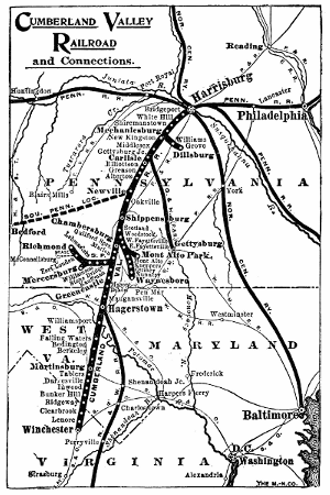
Figure 4.—Map of the Cumberland Valley Railroad as it appeared in 1919.
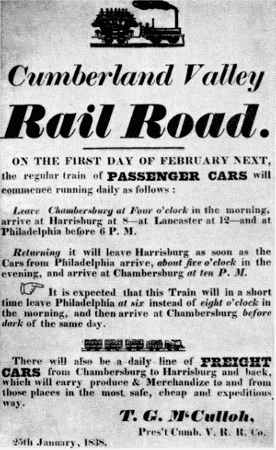
Figure 5.—An early broadside of the Cumberland Valley Railroad.
According to statements of Smith and the Board of Managers quoted on page 244, the Pioneer and the Jenny Lind were not new when purchased from their maker, Seth Wilmarth. Although of recent manufacture, previous to June 1851, they were apparently doing service on a road in Norwich, Connecticut. It should be mentioned that both Smith and Tyler were formerly associated with the Norwich and Worcester Railroad and they probably learned of these two engines through this former association. It is possible that the engines were purchased from Wilmarth by the Cumberland Valley road, which had bought several other locomotives from Wilmarth in previous years. It was the practice of at least one other New England engine builder, the Taunton Locomotive Works, to manufacture engines on the speculation that a buyer would be found; if no immediate buyers appeared the engine was leased to a local road until a sale was made.[6]
Regarding the Jenny Lind and Pioneer, Smith reported[7] to the Board of Managers at their meeting of March 17, 1852:
The small tank engines which were purchased last year … and which I spoke in a former report as undergoing at that time some necessary improvements have since that time been fairly tested as to their capacity to run our passenger trains and proved to be equal to the duty.
The improvements proposed to be made have been completed only on one engine [Jenny Lind] which is now running regularly with passenger trains—the cost of repairs and improvements on this engine (this being the one accidentally broken on the trial) amounted to $476.51. The other engine is now in the shop, not yet ready for service but will be at an early day.
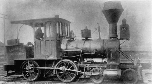
Figure 6.—The “Utility” as rebuilt to an 8-wheel engine, about 1863 or 1864. It was purchased by the Carlisle Manufacturing Co. in 1882 and was last used in 1896. (Smithsonian photo 36716F.)
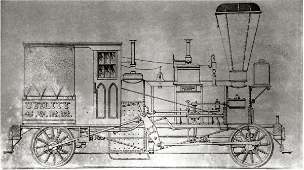
Figure 7.—The “Utility,” designed by Smith A. F. and constructed by Seth Wilmarth in 1854, was built to haul trains across the bridge at Harrisburg, Pa.
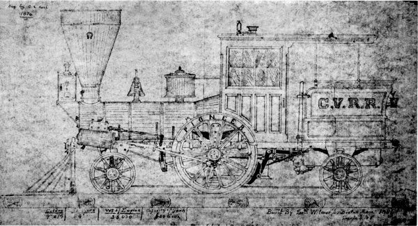
Figure 8.—The earliest known illustration of the Pioneer, drawn by A. S. Hull, master mechanic of the Cumberland Valley Railroad in 1876. It depicts the engine as it appeared in 1871. (Courtesy of Paul Westhaeffer.)
The Pioneer and Jenny Lind achieved such success in action that the president of the road, Frederick Watts, commented on their performance in the annual report of the Cumberland Valley Railroad for 1851. Watts stated that since their passenger trains were rarely more than a baggage car and two coaches, the light locomotives “… have been found to be admirably adapted to our business.” The Cumberland Valley Railroad, therefore, added two more locomotives of similar design in the next few years. These engines were the Boston and the Enterprise, also built by Wilmarth in 1854-1855.
Watts reported the Pioneer and Jenny Lind cost $7,642. A standard 8-wheel engine cost about $6,500 to $8,000 each during this period. In recent years, the Pennsylvania Railroad has stated the Pioneer cost $6,200 in gold, but is unable to give the source for this information. The author can discount this statement for it does not seem reasonable that a light, cheap engine of the pattern of the Pioneer could cost as much as a machine nearly twice its size.
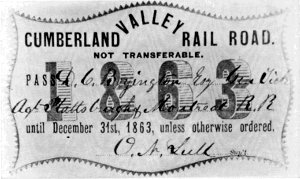
Figure 9.—Annual pass of the Cumberland Valley Railroad issued in 1863.
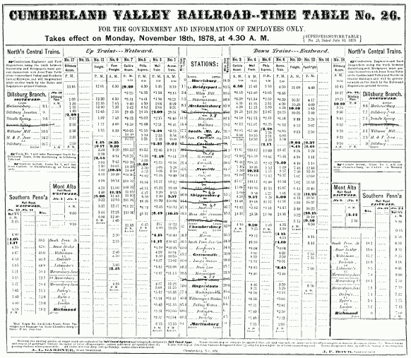
Figure 10.—Timetable of the Cumberland Valley Railroad for 1878.
Service History of the Pioneer
After being put in service, the Pioneer continued to perform well and was credited as able to move a 4-car passenger train along smartly at 40 mph.[8] This tranquility was shattered in October 1862 by a raiding party led by Confederate General J. E. B. Stuart which burned the Chambersburg shops of the Cumberland Valley Railroad. The Pioneer, Jenny Lind, and Utility were partially destroyed. The Cumberland Valley Railroad in its report for 1862 stated:
The Wood-shop, Machine-shop, Black-smith-shop, Engine-house, Wood-sheds, and Passenger Depot were totally consumed, and with the Engine-house three second-class Engines were much injured by the fire, but not so destroyed but that they may be restored to usefulness.
However, no record can be found of the extent or exact nature of the damage. The shops and a number of cars were burned so it is reasonable to assume that the cab and other wooden parts of the locomotive were damaged. One unverified report in the files of the Pennsylvania Railroad states that part of the roof and brick wall fell on the Pioneer during the fire causing considerable damage. In June 1864 the Chambersburg shops were again burned by the Confederates, but on this occasion the railroad managed to remove all its locomotives before the raid. During the Civil War, the Cumberland Valley Railroad was obliged to operate longer passenger trains to satisfy the enlarged traffic. The Pioneer and its sister single-axle engines were found too light for these trains and were used only on work and special trains. Reference to table 1 will show that the mileage of the Pioneer fell off sharply for the years 1860-1865.
Table 1.—Yearly Mileage of the Pioneer (From Annual Reports of the Cumberland Valley Railroad)
Year:Miles
1852 [a] 3,182
1853 [b] 20,722
185418,087
185514,151
185620,998
185722,779
185829,094
185929,571
18604,824
18614,346
1862( [c] )
18635,339
1864224
18652,215
186620,546
18675,709
186813,626
18691,372
1870…
18712,102
18724,002
18733,721
18743,466
1875636
1876870
1877406
18784,433
1879…
18808,306
1881( [d] )
Total [e] 244,727
In 1871 the Pioneer was remodeled by A. S. Hull, master mechanic of the railroad. The exact nature of the alterations cannot be determined, as no drawings or photographs of the engine previous to this time are known to exist. In fact, the drawing (fig. 8) prepared by Hull in 1876 to show the engine as remodeled in 1871 is the oldest known illustration of the Pioneer. Paul Westhaeffer, a lifelong student of Cumberland Valley R. R. history, states that according to an interview with one of Hull’s descendants the only alteration made to the Pioneer during the 1871 “remodeling” was the addition of a handbrake. The road’s annual report of 1853 describes the Pioneer as a six-wheel tank engine. The report of 1854 mentions that the Pioneer used link motion. These statements are enough to give substance to the idea that the basic arrangement has survived unaltered and that it has not been extensively rebuilt, as was the Jenny Lind in 1878.
By the 1870’s, the Pioneer was too light for the heavier cars then in use and by 1880 it had reached the end of its usefulness for regular service. After nearly thirty years on the road it had run 255,675 miles. Two new passenger locomotives were purchased in 1880 to handle the heavier trains. In 1881 the Pioneer was dropped from the roster, but was used until about 1890 for work trains. After this time it was stored in a shed at Falling Spring, Pennsylvania, near the Chambersburg yards of the C.V.R.R.
Mechanical Description of the Pioneer
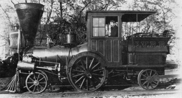
Figure 11.—“Pioneer,” about 1901, scene unknown. (Photo courtesy of Thomas Norrell.)
After the early 1840’s the single-axle locomotive, having one pair of driving wheels, was largely superseded by the 8-wheel engine. The desire to operate longer trains and the need for engines of greater traction to overcome the steep grades of American roads called for coupled driving wheels and machines of greater weight than the 4—2—0. After the introduction of the 4—4—0, the single-axle engine received little attention in this country except for light service or such special tasks as inspection or dummy engines.
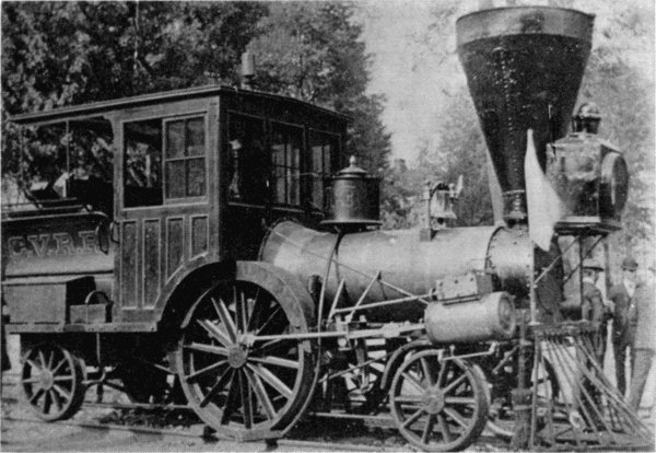
Figure 12.—The “Pioneer” in Carlisle, Pa., 1901. (Photo courtesy of Thomas Norrell.)
There was, however, a renewed interest in “singles” in the early 1850’s because of W. B. Adams’ experiments with light passenger locomotives in England. In 1850 Adams built a light single-axle tank locomotive for the Eastern Counties Railway which proved very economical for light passenger traffic. It was such a success that considerable interest in light locomotives was generated in this country as well as in England. Nearly 100 single-axle locomotives were built in the United States between about 1845-1870. These engines were built by nearly every well-known maker, from Hinkley in Boston to the Vulcan Foundry in San Francisco. Danforth Cooke & Co. of Paterson built a standard pattern 4—2—4 used by many roads. One of these, the C. P. Huntington, survives to the present time.
The following paragraphs describe the mechanical details of the Pioneer as it appears on exhibition in the Smithsonian Institution’s new Museum of History and Technology.
BOILER
The boiler is the most important and costly part of a steam locomotive, representing one-fourth to one-third of the total cost. A poorly built or designed boiler will produce a poor locomotive no matter how well made the remainder of mechanism. The boiler of the Pioneer is of the wagon-top, crownbar, fire-tube style and is made of a 5/16-inch thick, wrought-iron plate. The barrel is very small, in keeping with the size of the engine, being only 27 inches in diameter. While some readers may believe this to be an extremely early example of a wagon-top boiler, we should remember that most New England builders produced few locomotives with the Bury (dome) boiler and that the chief advocates of this later style were the Philadelphia builders. By the early 1850’s the Bury boiler passed out of favor entirely and the wagon top became the standard type of boiler with all builders in this country.
Sixty-three iron tubes, 17/8 inches by 85 inches long are used. The original tubes may have been copper or brass since these were easier to keep tight than the less malleable iron tubes. The present tube sheet is of iron but was originally copper. Its thickness cannot be conveniently measured, but it is greater than that of the boiler shell, probably about 1/2 to 5/8 inch. While copper tubes and tube sheets were not much used in this country after about 1870, copper was employed as recently as 1950 by Robert Stephenson & Hawthorns, Ltd., on some small industrial locomotives.
The boiler shell is lagged with wooden tongue-and-groove strips about 21/2 inches wide (felt also was used for insulation during this period). The wooden lagging is covered with Russia sheet iron which is held in place and the joints covered by polished brass bands. Russia sheet iron is a planish iron having a lustrous, metallic gray finish.
Alba F. Smith
Alba F. Smith, the man responsible for the purchase of the Pioneer, was born in Lebanon, Connecticut, June 28, 1817.[9] Smith showed promise as a mechanic at an early age and by the time he was 22 had established leadpipe works in Norwich. His attention was drawn particularly to locomotives since the tracks of the Norwich and Worcester Railroad passed his shop. His attempts to develop a spark arrester for locomotives brought Smith to the favorable attention of Captain Daniel Tyler (1799-1882), president of the Norwich and Worcester Railroad. When Tyler was hired by the Cumberland Valley Railroad in 1850 to supervise the line’s rebuilding, he persuaded the managers of that road to hire Smith as superintendent of machinery.[10] Smith was appointed as superintendent of the machine shop of the Cumberland Valley Railroad on July 22, 1850.[11] On January 1, 1851, he became superintendent of the road.
In March of 1856 Smith resigned his position with the Cumberland Valley Railroad and became superintendent of the Hudson River Railroad, where he remained for only a year. During that time he designed the coal-burning locomotive Irvington, rebuilt the Waterman condensing dummy locomotive for use in hauling trains through city streets, and developed a superheater.[12]
After retiring from the Hudson River Railroad he returned to Norwich and became active in enterprises in that area, including the presidency of the Norwich and Worcester Railroad. While the last years of Smith’s life were devoted to administrative work, he found time for mechanical invention as well. In 1862 he patented a safety truck for locomotives, and became president of a concern which controlled the most important patents for such devices.[13] Alba F. Smith died on July 21, 1879, in Norwich, Connecticut.
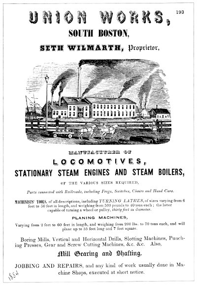
Figure 13.—Advertisement of Seth Wilmarth appearing in Boston city directory for 1848-1849.
Click here for transcription of advertisement.
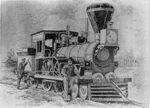
Figure 14.—The “Fury,” built for the Boston and Worcester Railroad in 1849 by Wilmarth. It was known as a “Shanghai” because of its great height. (Smithsonian Chaney photo 6443.)
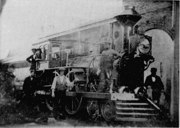
Figure 15.—The “Neptune,” built for the Boston and Worcester in 1847 by Hinkley and Drury. Note the similarity of this engine and the Fury.
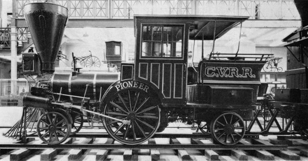
Figure 16.—The “Pioneer” as first exhibited in the Arts and Industries building of the Smithsonian Institution prior to restoration of the sandbox. (Smithsonian photo 48069D.)
[BOILER continued]
The steam dome (fig. 18) is located directly over the firebox, inside the cab. It is lagged and jacketed in an identical manner to the boiler. The shell of the dome is of 5/16-inch wrought iron, the top cap is a cast-iron plate which also serves as a manhole cover offering access to the boiler’s interior for inspection and repair.
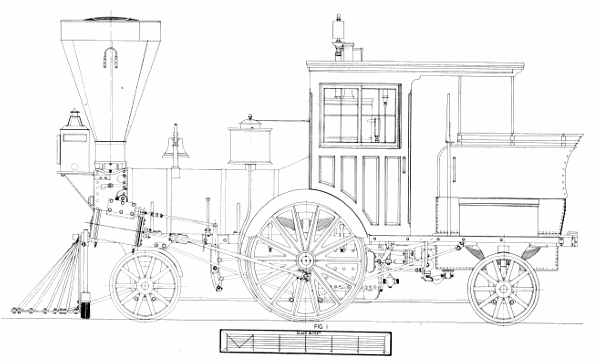
Figure 17.—“Pioneer” locomotive. (Drawing by J. H. White.)
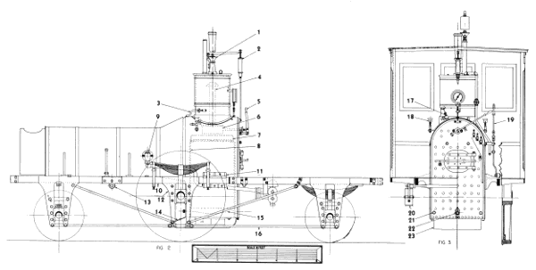
Figure 18.—“Pioneer” locomotive, (1) Safety valve, (2) spring balance, (3) steam jet, (4) dry pipe, (5) throttle lever, (6) throttle, (7) crown bar, (8) front tube sheet, (9) check valve, (10) top rail, (11) rear-boiler bracket, (12) pedestal, (13) rocker bearing, (14) damper, (15) grate, (16) bottom rail, (17) pump heater valve, (18) cylinder lubricator, (19) reversing lever, (20) brake shoe, (21) mud ring, (22) blowoff cock, (23) ashpan. (Drawing by J. H. White.)
A round plate, 20 inches in diameter, riveted on the forward end of the boiler, just behind the bell stand, was found when the old jacket was removed in May 1963. The size and shape of the hole, which the plate covers, indicate that a steam dome or manhole was located at this point. It is possible that this was the original location of the steam dome since many builders in the early 1850’s preferred to mount the dome forward of the firebox. This was done in the belief that there was less danger of priming because the water was less agitated forward of the firebox.
The firebox is as narrow as the boiler shell and fits easily between the frame. It is a deep and narrow box, measuring 27 inches by 28 inches by about 40 inches deep, and is well suited to burning wood. A deep firebox was necessary because a wide, shallow box suitable for coal burning, allowed the fuel to burn so quickly it was difficult to fire the engine effectively. With the deep, narrow firebox, wood was filled up to the level of the fire door. In this way, the fire did not burn so furiously and did not keep ahead of the fireman; at the same time, since it burned so freely, a good fire was always on hand. The Pioneer burned oak and hickory.[14] For the firebox 5/16-inch thick sheet was used, for heavier sheet would have blistered and flaked off because of the intense heat of the fire and the fibrous quality of wrought-iron sheet of the period. Sheet iron was fabricated from many small strips of iron rolled together while hot. These strips were ideally welded into a homogeneous sheet, but in practice it was found the thicker the sheet the less sure the weld.
The fire grates are cast iron and set just a few inches above the bottom of the water space so that the water below the grates remains less turbulent and mud or other impurities in the water settle here. Four bronze mud plugs and a blowoff cock are fitted to the base of the firebox so that the sediment thus collected can be removed (figs. 17, 18).
The front of the boiler is attached to the frame by the smokebox, which is a cylinder, bolted on a light, cast-iron saddle (not part of the cylinder castings nor attached to them, but bolted directly to the top rail of the frame; it may be a hastily made repair put on at the shops of the C.V.R.R.). The rear of the boiler is attached to the frame by two large cast-iron brackets, one on each side of the firebox (fig. 18). These are bolted to the top rail of the frame but the holes in the brackets are undoubtedly slotted, so that they may slide since the boiler will expand about 1/4 inch when heated. In addition to the crown bars, which strengthen the crown sheet, the boiler is further strengthened by stay bolts and braces located in the wagon top over the firebox, where the boiler had been weakened by the large hole necessary for the steam dome. This boiler is a remarkably light, strong, and compact structure.
BOILER FITTINGS
Few boiler fittings are found on the Pioneer and it appears that little was done to update the engine with more modern devices during its many years of service. With the exception of the steam gauge, it has no more boiler fitting than when it left the builder’s shop in 1851.
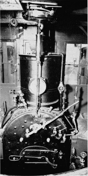
Figure 19.—Backhead of the Pioneer. (Smithsonian photo 48069F.)
The throttle valve is a simple slide valve and must have been primitive for the time, for the balance-poppet throttle valve was in use in this country previous to 1851. It is located directly below the steam dome even though it was common practice to place the throttle valve at the front of the boiler in the smokebox. Considering the cramped condition inside the smokebox, there would seem to be little space for the addition of the throttle valve; hence its present location. The dry pipe projects up into the steam dome to gather the hottest, driest steam for the cylinders. The inverted, funnel-like cap on the top of the dry pipe is to prevent priming, as drops of water may travel up the sides of the pipe and then to the cylinders, with the possibility of great damage. After the steam enters the throttle valve it passes through the front end of the valve, through the top of the boiler via the dry pipe (fig. 18), through the front tube sheet, and then to the cylinders via the petticoat pipes. The throttle lever is a simple arrangement readily understood from the drawings. It has no latch and the throttle lever is held in any desired setting by the wingnut and quadrant shown in figure 18. The water level in the boiler is indicated by the three brass cocks located on the backhead. No gauge glass is used; they were not employed in this country until the 1870’s, although they were commonly used in England at the time the Pioneer was built.
While two safety valves were commonly required, only one was used on the Pioneer. The safety valve is located on top of the steam dome. Pressure is exerted on the lever by a spring balance, fixed at the forward end by a knife-blade bearing. The pressure can be adjusted by the thumbscrew on the balance. The graduated scale on the balance gave a general but uncertain indication of the boiler pressure. The valve itself is a poppet held against the face of the valve seat by a second knife blade attached to the lever. The ornamental column forming the stand of the safety valve is cast iron and does much to decorate the interior of the cab. The pipe carrying the escaping steam projects through the cab roof. It is made of copper with a decorative brass band. This entire mechanism was replaced by a modern safety valve for use at the Chicago Railroad Fair (1949). Fortunately, the old valve was preserved and has since been replaced on the engine.
The steam gauge is a later addition, but could have been put on as early as the 1860’s, since the most recent patent date that it bears is 1859. It is an Ashcroft gauge having a handsome 4—4—0 locomotive engraved on its silver face.
The steam jet (item 3, fig. 18) is one of the simplest yet most notable boiler fitting of the Pioneer, being nothing more than a valve tapped into the base of the steam dome with a line running under the boiler jacket to the smokestack. When the valve is opened a jet of steam goes up the stack, creating a draft useful for starting the fire or enlivening it as necessary. This device was the invention of Alba F. Smith in 1852, according to the eminent 19th-century technical writer and engineer Zerah Colburn.[15]
The two feedwater pumps (fig. 20) are located beneath the cab deck (1, fig. 17). They are cast-iron construction and are driven by an eccentric on the driving-wheel axle (fig. 27). The airchamber or dome (1, fig. 27) imparts a more steady flow of the water to the boiler by equalizing the surges of water from the reciprocating pump plunger. A steam line (3, fig. 18), which heats the pump and prevents freezing in cold weather, is regulated by a valve in the cab (figs. 18, 27). Note that the line on the right side of the cab has been disconnected and plugged.
The eccentric drive for the pumps is unusual, and the author knows of no other American locomotive so equipped. Eastwick and Harrison, it is true, favored an eccentric drive for feed pumps, but they mounted the eccentric on the crankpin of the rear driving wheel and thus produced in effect a half-stroke pump. This was not an unusual arrangement, though a small crank was usually employed in place of the eccentric. The full-stroke crosshead pump with which the Jenny Lind (fig. 22) is equipped, was of course the most common style of feed pump used in this country in the 19th century.
Of all the mechanisms on a 19th-century locomotive, the feed pump was the most troublesome. If an engineer could think of nothing else to complain about, he could usually call attention to a defective pump and not be found a liar. Because of this, injectors were adopted after their introduction in 1860. It is surprising that the Pioneer, which was in regular service as late as 1880 and has been under steam many times since for numerous exhibitions, was never fitted with one of these devices. Because its stroke is short and the plunger is in less rapid motion, the present eccentric arrangement is more complex but less prone to disorder than the simpler but faster crosshead pump.
Seth Wilmarth
Little is known of the builder of the Pioneer, Seth Wilmarth, and nothing in the way of a satisfactory history of his business is available. For the reader’s general interest the following information is noted.[16]
Seth Wilmarth was born in Brattleboro, Vermont, on September 8, 1810. He is thought to have learned the machinist trade in Pawtucket, Rhode Island, before coming to Boston and working for the Boston Locomotive Works, Hinkley and Drury proprietors. In about 1836 he opened a machine shop and, encouraged by an expanding business, in 1841 he built a new shop in South Boston which became known as the Union Works. [17] Wilmarth was in the general machine business but his reputation was made in the manufacture of machine tools, notably lathes. He is believed to have built his first locomotive in 1842, but locomotive building never became his main line of work. Wilmarth patterned his engines after those of Hinkley and undoubtedly, in common with the other New England builders of this period, favored the steady-riding, inside-connection engines. The “Shanghais,” so-called because of their great height, built for the Boston and Worcester Railroad by Wilmarth in 1849, were among the best known inside-connection engines operated in this country (fig. 14). While the greater part of Wilmarth’s engines was built for New England roads, many were constructed for lines outside that area, including the Pennsylvania Railroad, Ohio and Pennsylvania Railroad, and the Erie.
A comparison of the surviving illustrations of Hinkley and Wilmarth engines of the 1850’s reveals a remarkable similarity in their details (figs. 14 and 15). Notice particularly the straight boiler, riveted frame, closely set truck wheels, feedwater pump driven by a pin on the crank of the driving wheel, and details of the dome cover. All of the features are duplicated exactly by both builders. This is not surprising considering the proximity of the plants and the fact that Wilmarth had been previously employed by Hinkley.
In 1854 Wilmarth was engaged by the New York and Erie Railroad to build fifty 6-foot gauge engines. [18] After work had been started on these engines, and a large store of material had been purchased for their construction, Wilmarth was informed that the railroad could not pay cash but that he would have to take notes in payment. [19] There was at this time a mild economic panic and notes could be sold only at a heavy discount. This crisis closed the Union Works. The next year, 1855, Seth Wilmarth was appointed master mechanic of the Charlestown Navy Yard, Boston, where he worked for twenty years. He died in Malden, Massachusetts, on November 5, 1886.
[BOILER FITTINGS continued]
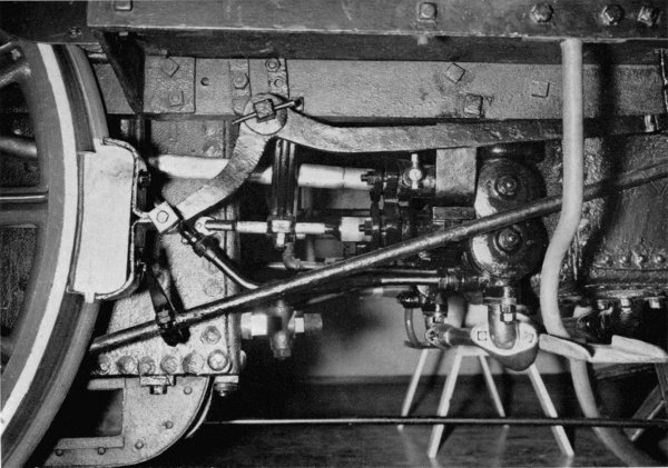
Figure 20.—Feedwater pump of the Pioneer. (Smithsonian photo 63344.)
The check valves are placed slightly below the centerline of the boiler (fig. 18). These valves are an unfinished bronze casting and appear to be of a recent pattern, probably dating from the 1901 renovation. At the time the engine was built, it was usual to house these valves in an ornamental spun-brass casing. The smokestack is of the bonnet type commonly used on wood-burning locomotives in this country between about 1845 and 1870. The exhaust steam from the cylinders is directed up the straight stack (shown in phantom in fig. 27) by the blast pipe. This creates a partial vacuum in the smokebox that draws the fire, gases, ash, and smoke through the boiler tubes from the firebox. The force of the exhausting steam blows them out the stack. At the top of the straight stack is a deflecting cone which slows the velocity of the exhaust and changes its direction causing it to go down into the funnel-shaped outer casing of the stack. Here, the heavy embers and cinders are collected and prevented from directly discharging into the countryside as dangerous firebrands. Wire netting is stretched overtop of the deflecting cone to catch the lighter, more volatile embers which may defy the action of the cone. The term “bonnet stack” results from the fact that this netting is similar in shape to a lady’s bonnet. The cinders thus accumulated in the stack’s hopper could be emptied by opening a plug at the base of the stack.
While the deflecting cone was regarded highly as a spark arrester and used practically to the exclusion of any other arrangement, it had the basic defect of keeping the smoke low and close to the train. This was a great nuisance to passengers, as the low trailing smoke blew into the cars. If the exhaust had been allowed to blast straight out the stack high into the air, most of the sparks would have burned out before touching the ground.
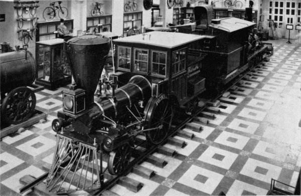
Figure 21.—“Pioneer” on exhibit in old Arts and Industries building of the Smithsonian Institution. In this view can be seen the bonnet screen of the stack and arrangement of the boiler-frame braces and other details not visible from the floor. (Smithsonian photo 48069A.)
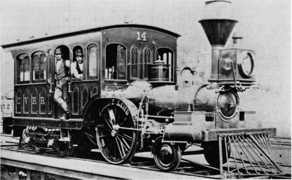
Figure 22.—“Jenny Lind,” sister engine of the Pioneer, shown here as rebuilt in 1878 for use as an inspection engine. It was scrapped in March 1905. (Photo courtesy of E. P. Alexander.)
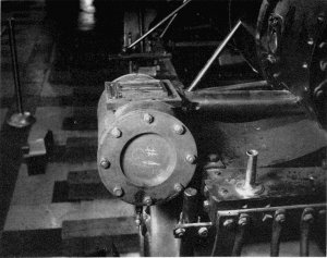
Figure 23.—Cylinder head with valve box removed.
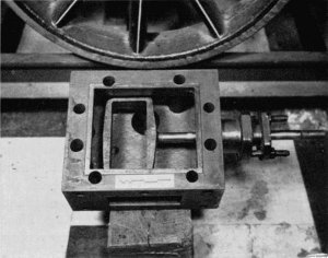
Figure 24.—Bottom of valve box with slide valve removed.
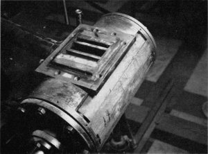
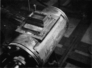
Figures 25 and 26.—Cylinder with valve box removed, showing valve face.
FRAME
The frame of the Pioneer defies an exact classification but it more closely resembles the riveted- or sandwich-type frame than any other (figs. 18, 27). While the simple bar frame enjoyed the greatest popularity in the last century, riveted frames were widely used in this country, particularly by the New England builders between about 1840 and 1860. The riveted frame was fabricated from two plates of iron, about 5/8-inch thick, cut to the shape of the top rail and the pedestal. A bar about 2 inches square was riveted between the two plates. A careful study of photographs of Hinkley and other New England-built engines of the period will reveal this style of construction. The frame of the Pioneer differs from the usual riveted frame in that the top rail is 13/4 inches thick by 41/8 inches deep and runs the length of the locomotive. The pedestals are made of two 3/8-inch plates flush-riveted to each side of the top rail. The cast-iron shoes which serve as guides for the journal boxes also act as spacers between the pedestal plates.
The bottom rail of the frame is a 11/8-inch diameter rod which is forged square at the pedestals and forms the pedestal cap. The frame is further stiffened by two diagonal rods running from the top of each truck-wheel pedestal to the base of the driving-wheel pedestal, forming a truss. Six rods, riveted to the boiler shell and bolted to the frame’s top rail, strengthen the frame laterally. Four of these rods can be seen easily as they run from the frame to the middle of the boiler; the other two are riveted to the underside of the boiler. The attachment of these rods to the boiler was an undesirable practice, for the boiler shell was thus subjected to the additional strain of the locomotive’s vibrations as it passed over the road. In later years, as locomotives grew in size, this practice was avoided and frames were made sufficiently strong to hold the engine’s machinery in line without using the boiler shell.
The front and rear frame beams are of flat iron plate bolted to the frame. The rear beam had been pushed in during an accident, and instead of its being replaced, another plate was riveted on and bent out in the opposite direction to form a pocket for the rear coupling pin. Note that there is no drawbar and that the coupler is merely bolted to the beams. Since the engine only pulled light trains, the arrangement was sufficiently strong.
RUNNING GEAR
The running gear is simply sprung with individual leaf springs for each axle; it is not connected by equalizing levers. To find an American locomotive not equipped with equalizers is surprising since they were almost a necessity to produce a reasonably smooth ride on the rough tracks of American railroads. Equalizers steadied the motion of the engine by distributing the shock received by any one wheel or axle to all the other wheels and axles so connected, thus minimizing the effects of an uneven roadbed. The author believes that the Pioneer is a hard-riding engine.
The springs of the main drives are mounted in the usual fashion. The rear boiler bracket (fig. 18) is slotted so that the spring hanger may pass through for its connection with the frame. The spring of the leading wheels is set at right angles to the frame (fig. 27) and bears on a beam, fabricated of iron plate, which in turn bears on the journal boxes. The springs of the trailing wheels are set parallel with the frame and are mounted between the pedestal plates (fig. 18).
The center of the driving wheel is cast iron and has spokes of the old rib pattern, which is a T in cross section, and was used previous to the adoption of the hollow spoke wheel. In the mid-1830’s Baldwin and others used this rib-pattern style of wheel, except that the rib faced inside. The present driving-wheel centers are unquestionably original. The sister engine Jenny Lind (fig. 22) was equipped with identical driving wheels. The present tires are very thin and beyond their last turning. They are wrought iron and shrunk to fit the wheel centers. Flush rivets are used for further security. The left wheel, shown in figure 17, is cracked at the hub and is fitted with an iron ring to prevent its breaking.
The truck wheels, of the hollow spoke pattern, are cast iron with chilled treads. They were made by Asa Whitney, one of the leading car-wheel manufacturers in this country, whose extensive plant was located in Philadelphia. Made under Whitney’s patent of 1866, these wheels may well have been added to the Pioneer during the 1871 rebuilding. Railroad wheels were not cast from ordinary cast iron, which was too weak and brittle to stand the severe service for which they were intended, but from a high-quality cast iron similar to that used for cannons. Its tensile strength, which ranged from 31,000 to 36,000 psi, was remarkably high and very nearly approached that of the best wrought-iron plate.
The cylinders are cast iron with an 81/2-inch bore about half the size of the cylinders of a standard 8-wheel engine. The cylinders are bolted to the frame but not to the saddle, and are set at a 9° angle to clear the leading wheels and at the same time to line up with the center of the driving-wheel axle. The wood lagging is covered with a decorative brass jacket. Ornamental brass jacketing was extensively used on mid-19th-century American locomotives to cover not only the cylinders but steam and sand boxes, check valves, and valve boxes. The greater expense for brass (Russia iron or painted sheet iron were a cheaper substitute) was justified by the argument that brass lasted the life of the engine, and could be reclaimed for scrap at a price approaching the original cost; and also that when brightly polished it reflected the heat, preventing loss by radiation, and its bright surface could be seen a great distance, thus helping to prevent accidents at grade crossings. The reader should be careful not to misconstrue the above arguments simply as rationalization on the part of master mechanics more intent on highly decorative machines than on the practical considerations involved.
The valve box, a separate casting, is fastened to the cylinder casting by six bolts. The side cover plates when removed show only a small opening suitable for inspection and adjustment of the valve. The valve box must be removed to permit repair or removal of the valve. A better understanding of this mechanism and the layout of the parts can be gained from a study of figures 23-26, 28 (8, 8A, and 8B).
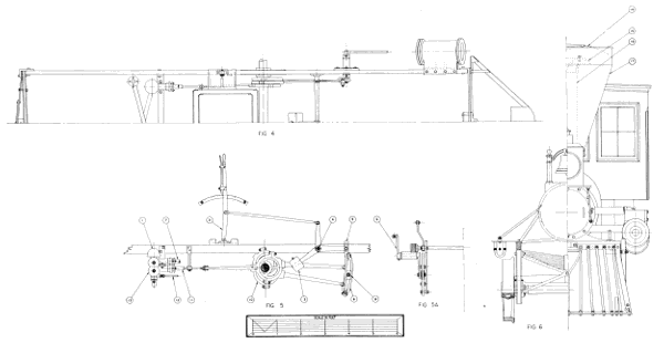
Figure 27.—“Pioneer” locomotive. (1) Air chamber, (2) reversing lever, (3) counterweight, (4) reversing shaft, (5) link hanger, (6) rocker, (7) feedwater line to boiler, (8) link block, (9) link, (10) eccentric, (11) pump plunger, (12) pump steamheater line, (13) feedwater pump, (14) wire netting [bonnet], (15) deflecting cone, (16) stack, (17) stack hopper. (Drawing by J. H. White.)
Click on image to view larger sized.
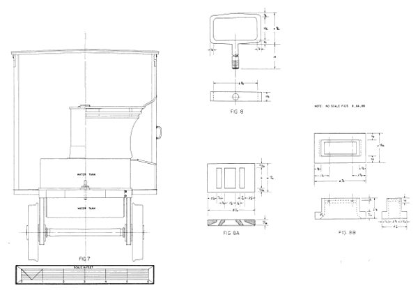
Figure 28.—Rear elevation of Pioneer and detail of valve shifter; valve face and valve. (Drawing by J. H. White.)
Click on image to view larger sized.
Both crossheads were originally of cast iron but one of these has been replaced and is of steel. They run into steel guides, bolted at the forward end to the rear cylinder head and supported in the rear by a yoke. The yoke is one of the more finished and better made pieces on the entire engine (fig. 27). The main rod is of the old pattern, round in cross section, and only 11/2 inches in diameter at the largest point.
VALVE GEAR
The valve gear is of the Stephenson shifting-link pattern (see fig. 27), a simple and dependable motion used extensively in this country between about 1850 and 1900. The author believes that this is the original valve gear of the Pioneer, since the first mention (1854) in the Annual Report of the Cumberland Valley Railroad of the style of valve gear used by each engine, states that the Pioneer was equipped with a shifting-link motion. Assuming this to be the original valve gear of the Pioneer, it must be regarded as an early application, because the Stephenson motion was just being introduced into American locomotive practice in the early 1850’s. Four eccentrics drive the motion; two are for forward motion and two for reverse. The link is split and made of two curved pieces. The rocker is fabricated of several forged pieces keyed and bolted together. On better made engines the rocker would be a one-piece forging. The lower arm of each rocker is curiously shaped, made with a slot so that the link block may be adjusted. Generally, the only adjustment possible was effected by varying the length of the valve stem by the adjusting nuts provided. A simple weight and lever attached to the reversing shaft serve as a counterbalance for the links and thus assist the engineer in shifting the valve motion. There are eight positions on the quadrant of the reversing lever.
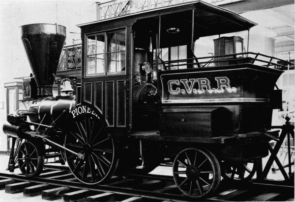
Figure 29.—“Pioneer” on exhibit in old Arts and Industries building, showing the tank and backhead. (Smithsonian photo 48069E.)
MISCELLANEOUS NOTES
The cab is solid walnut with a natural finish. It is very possible that the second cab was added to the locomotive after the 1862 fire. A brass gong used by the conductor to signal the engineer is fastened to the underside of the cab roof. This style of gong was in use in the 1850’s and may well be original equipment.
The water tank is in two sections, one part extending below the deck, between the frame. The tank holds 600 gallons of water. The tender holds one cord of wood.
The small pedestal-mounted sandbox was used on several Cumberland Valley engines including the Pioneer. This box was removed from the engine sometime between 1901 and 1904. It was on the engine at the time of the Carlisle sesquicentennial but disappeared by the time of the St. Louis exposition. Two small sandboxes, mounted on the driving-wheel splash guards, replaced the original box. The large headlamp (fig. 3) apparently disappeared at the same time and was replaced by a crudely made lamp formerly mounted on the cab roof as a backup light. Headlamps of commercial manufacture were carefully finished and made with parabolic reflectors, elaborate burners, and handsomely fitted cases. Such a lamp could throw a beam of light for 1000 feet. The present lamp has a flat cone-shaped piece of tin for a reflector.
The brushes attached to the pilot were used in the winter to brush snow and loose ice off the rail and thus improve traction. In good weather the brushes were set up to clear the tracks.
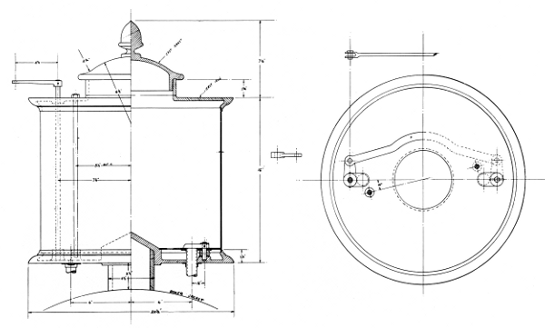
Figure 30.—Reconstructed sandbox replaced on the locomotive, August 1962. (Drawing by J. H. White.)
After the Pioneer had come to the National Museum, it was decided that some refinishing was required to return it as nearly as possible to the state of the original engine. Replacing the sandbox was an obvious change.[20] The brass cylinder jackets were also replaced. The cab was stripped and carefully refinished as natural wood. The old safety valve was replaced, as already mentioned. Rejacketing the boiler with simulated Russia iron produced a most pleasing effect, adding not only to the authenticity of the display but making the engine appear lighter and relieving the somber blackness which was not characteristic of a locomotive of the 1850’s. Several minor replacements are yet to be done; chiefly among these are the cylinder-cock linkage and a proper headlamp.
The question arises, has the engine survived as a true and accurate representation of the original machine built in 1851? In answer, it can be said that although the Pioneer was damaged en route to the Cumberland Valley Railroad, modified on receipt, burned in 1862, and operated for altogether nearly 40 years, surprisingly few new appliances have been added, nor has the general arrangement been changed. Undoubtedly, the main reason the engine is so little changed is that its small size and odd framing did not invite any large investment for extensive alteration for other uses. But there can be no positive answer as to its present variance from the original appearance as represented in the oldest known illustration of it—the Hull drawing of 1871 (fig. 8). There are few, if any, surviving 19th-century locomotives that have not suffered numerous rebuildings and are not greatly altered from the original. The John Bull, also in the U.S. National Museum collection, is a good example of a machine many times rebuilt in its 30 years of service.[21] Unless other information is uncovered to the contrary, it can be stated that the Pioneer is a true representation of a light passenger locomotive of 1851.
Paper 42 - Transcriber’s Note
P. 259: ‘1880 and has been under steam’—was ‘1880 and has been under stream.’
P. 267: ‘made with parabolic reflectors’—was ‘made with parobolic reflectors.’
Transcription of Advertisement on Pg. 254
UNION WORKS, SOUTH BOSTON, SETH WILMARTH, Proprietor, MANUFACTURER OF LOCOMOTIVES, STATIONARY STEAM ENGINES AND STEAM BOILERS, OF THE VARIOUS SIZES REQUIRED, Parts connected with Railroads, including Frogs, Switches, Chairs and Hand Cars.MACHINISTS' TOOLS, of all descriptions, including TURNING LATHES, of sizes varying from 6 feet to 50 feet in length, and weighing from 500 pounds to 40 tons each; the latter capable of turning a wheel or pulley, thirty feet in diameter. PLANING MACHINES, Varying from 2 feet to 60 feet in length, and weighing from 200 lbs. to 70 tons each, and will plane up to 55 feet long and 7 feet square. Boring Mills, Vertical and Horizontal Drills, Slotting Machines, Punching Presses, Gear and Screw Cutting Machines, &c. &c. Also, Mill Gearing and Shafting. JOBBING AND REPAIRS, and any kind of work usually done in Machine Shops, executed at short notice.
Contributions from The Museum of History and Technology: Paper 43 History of the Division of Medical Sciences
Sami Hamarneh
SECTION OF MATERIA MEDICA (1881-1898) 272
DIVISION OF MEDICINE (1898-1939) 276
DIVISION OF MEDICINE AND PUBLIC HEALTH (1939-1957) 281
DIVISION OF MEDICAL SCIENCES (1957 TO PRESENT) 290
A NEW DIMENSION FOR THE HEALING ARTS 292
BIBLIOGRAPHY 297
INDEX
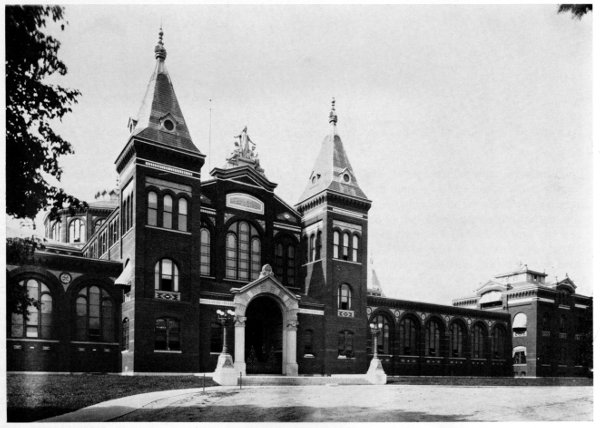
Figure 1.—Early View of the United States National Museum, known for the last quarter of a century as the Arts and Industries building. Completed in 1881, it housed the Division of Medical Sciences from its establishment in 1881 as a Section of Materia Medica to the time of the writing of this paper. While the medical collection remained in the Department of Arts and Industries, by the end of June 1912 practically all other collections belonging to the fields of natural history and anthropology were transferred to the then new Natural History building.
Sami Hamarneh
HISTORY of the DIVISION of MEDICAL SCIENCES In The Museum of History and Technology
This paper traces, for the first time, the history of the Division of Medical Sciences in the Museum of History and Technology from its small beginnings as a section of materia medica in 1881 to its present broad scope. The original collection of a few hundred specimens of crude drugs which had been exhibited at the centennial exhibition of 1876 at Philadelphia, has now developed into the largest collection in the Western Hemisphere of historical objects related to the healing arts.
The Author: Sami Hamarneh is the curator of the Division of Medical Sciences in the Smithsonian Institution’s Museum of History and Technology.
By the early 1870’s, leading figures from both the health professions and the general public had begun to realize the necessity for having the medical sciences represented in the Smithsonian Institution. The impetus behind this new feeling resulted from the action of a distinguished American physician, philanthropist, and author, Joseph Meredith Toner (1825-1896), and came almost a decade before the integration of a new section concerned with research and the historical and educational aspects of the healing arts in the Smithsonian Institution.
In 1872, Dr. Toner established the “Toner Lectures” to encourage efforts towards discovering new truths “for the advancement of medical science … for the benefit of mankind.” To finance these lectures, he provided a fund worth approximately $3,000 to be administered by a board of trustees consisting of the Secretary of the Smithsonian Institution, the Surgeon General of the U.S. Navy, the Surgeon General of the U.S. Army (only in some years), and the president of the Medical Society of the District of Columbia. The interest from this fund was to compensate physicians and scholars who were to deliver “at least two annual memoirs or essays” based on original research on some branch of the medical sciences and containing information which had been verified “by experiments or observations.” [1]
The Secretary of the Smithsonian Institution agreed to have these lectures published by the Institution in its Miscellaneous Collections. The first lecture given by the Assistant Surgeon of the U.S. Army, “On the Structure of Cancerous Tumors and the Mode in which Adjacent parts are Invaded,” deserves credit even by current standards of scientific research.[2] Only 10 lectures were given between 1873 and 1890 (see bibliography), despite the recommendation for at least two every year. [3]
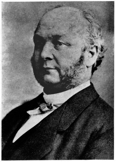
Figure 2.—Dr. Joseph M. Toner, a leading physician in Washington, D.C., and founder of the “Toner Lectures” for the promotion and advancement of medical education and research. In 1873, Dr. Toner became president of the American Medical Association and, in 1874, he became president of the American Public Health Association. He was a physician to St. Joseph’s Male Orphan Asylum and St. Ann’s Infants’ Asylum in Washington, D.C. In addition, he was instrumental in establishing Providence Hospital in the District of Columbia. He also provided a workable plan for the American Medical Association’s library in Washington, D.C. (1868-1871). Among his several publications are: Contributions to the Annals of Medical Progress and Medical Education in the United States before and during the War of Independence (Washington: Government Printing Office, 1874) and Medical Men of the Revolution (1876). In 1882, he donated his large library, consisting of 44,000 books and pamphlets on topics related mainly to medicine and history, to the Library of Congress. (Photo courtesy of National Library of Medicine.)