Front matter (continued 3)
Reading edition
It is interesting to note that it was indeed Bollman trusses to which the president of the railroad had referred. How much earlier than this date Bollman had evolved his peculiar trussing system is not clear. The certain influence of Latrobe’s radiating strut system of trussing has been mentioned. As likely an influence was another basic technique commonly used to increase the capacity of a simple timber beam—that of trussing—i.e., placing beneath the beam a rod of iron that was anchored at the ends of the beam and held a certain distance below it at the center by a vertical strut or post. This combination thus became a truss in that the timber portion was no longer subject to a bending stress but to a simple one of compression, the rod absorbing the tensile stress of the combination. The effect was to deepen the beam, increasing the distance between its extreme fibers and—by thus reducing the bending moment—reducing the stress in them (see fig. 3).
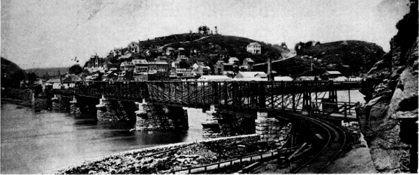
Figure 13.—The four Bollman spans at Harpers Ferry that survived the Civil War. The spans were completed in 1862-1863. (Photo courtesy of Baltimore and Ohio Railroad.)
It apparently occurred to Bollman that by extending the number of rods in a longitudinal direction, this effect could be practically amplified to such an extent as to be capable of spanning considerable distances. He almost certainly did not at first contemplate an all-iron system, but rather a composite one such as described. It is entirely likely that such trussed beams, with multiple systems of tension rods, were used by Bollman as bridging in temporary trestlework along the line as early as 1845 (see fig. 4).
It is impossible to say whether Bollman himself, or Latrobe, was struck with the logic of further elaborating upon the system and, simultaneously, translating the timber compression member into one of cast iron. Cast iron would naturally have been selected for a member that resisted a compressive stress, as it was considerably cheaper than wrought iron. But more important, at that time wrought iron was not available in shapes of sufficient sectional area to resist the appreciable buckling stresses induced in long compression members. The cost of building up members to sufficient size from the very limited selection of small shapes then rolled would have been prohibitive.
The trussing rods, subjected to tension, were of wrought iron inasmuch as the sectional area had only to be sufficient to resist the primary axial stress.
The first all-iron Bollman truss was constructed over the Little Patuxent River at Savage Factory, near Laurel, Maryland, in 1850. In the chief engineer’s report for the year 1850, Latrobe was able to state that the truss had been completed and was giving “much satisfaction.” He went on at some length to praise the “valuable mechanical features” embodied therein, and expressed great confidence that iron would become as important a material in the field of civil engineering as it was in mechanical engineering.
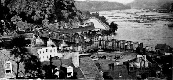
Figure 14.—The Harpers Ferry bridge as completed after the Civil War. It was used by the Baltimore and Ohio until 1894, and as a highway bridge until 1936. (Photo 690, Baltimore and Ohio Collection, Museum of History and Technology.)
The cost of this first major Bollman bridge was $23,825.00. Its span was 76 feet. Latrobe’s confidence was well placed. The Savage span and another at Bladensburg may be considered successful pilot models, for, in spite of a certain undercurrent of mistrust of iron bridges within the engineering profession—due mainly to a number of failures of improperly designed spans—Latrobe felt there was sufficient justification for the unqualified adoption of iron in all subsequent major bridge structures on the B. & O.
Almost immediately following completion of the Savage Bridge, Bollman undertook the design of replacements for the large Patapsco River span at Elysville (now Daniels), Maryland, and the so-called Winchester span of the B. & O.’s largest and most important bridge, that over the Potomac at Harpers Ferry. Harpers Ferry bridge, a timber structure, had been designed by Latrobe and built in 1836-1837 by the noted bridge constructor Lewis Wernwag. It was peculiar in having a turnout, near the Virginia shore, whereby a subsidiary road branched off to Winchester (see fig. 6). Only the single span on this line, situated between the midriver switch and the shore, was slated for replacement, as the other seven spans of the bridge had been virtually reconstructed in the decade or so of their history and were in sound condition at the time.
The Winchester span (fig. 8), which was the first Bollman truss to embody sufficient refinement of detail to be considered a prototype, was completed in 1851. Bollman was extremely proud of the work, with perfect justification it may be said. The 124-foot span was fabricated in the railroad’s extensive Mount Clair shops. It was subdivided into eight panels by seven struts and seven pairs of truss rods. An interesting difference between this span and Bollman’s succeeding bridges was his use of granite rather than cast iron for the towers. The span consisted of three parallel lines of trussing to accommodate a common road in addition to the single-track Winchester line.
The distinctive feature of the Bollman system was the previously mentioned series of diagonal truss links in combination with a cast-iron compression chord, which Bollman called the “stretcher.” The spacing between the chord and the junction of each pair of links was maintained by a vertical post or strut, also cast.
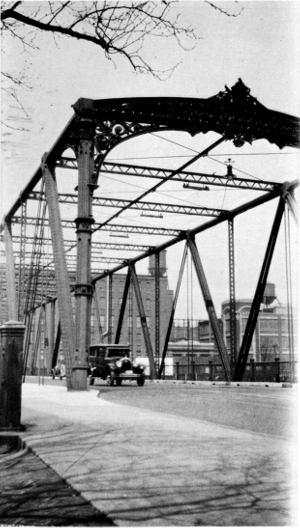
Figure 15.—North Street (now Guilford Avenue) bridge, Baltimore. In this transitional composite structure cast iron was used only in the relatively short sections of the upper chord. For the long unsupported compression members of the web system, standard wrought-iron angles and channels were built up into a large section. The decorative cast-iron end posts were non-structural. (Photo in the L. N. Edwards Collection, Museum of History and Technology.)
Much of the appeal of this design lay unquestionably in the sense of security derived from the fact that each of the systems acted independently to carry its load to the abutments. The lower chords, actually nonfunctional in the primary structure, were included merely to preserve the proper longitudinal spacing between the lower ends of the struts. A certain lack of rigidity was inherent in the system due to that very discontinuity which characterized its action; however, this was compensated for by a pair of light diagonal stay rods crossing each panel. These rods served the additional function of distributing concentrated loads to adjacent struts much in the manner of the bridging between floor joists in a building.
In the Winchester span the floor system was of timber for reasons of economy. This was a very minor weakness inasmuch as any stick could be quickly replaced, and without disturbing the function of the structure. Bollman received a patent for his truss in January 1852, and in the same year published a booklet describing his system in general and the Harpers Ferry span in particular. Here, he first calls it a “suspension and trussed bridge,” which is indeed an accurate designation for a system which is not strictly a truss because it has no active lower chord. (The analogy to a suspension bridge is quite clear, each pair of primary rods being comparable to a suspension cable.) Thereafter, Bollman’s invention was generally termed a suspension truss.
INFLUENCE OF THE TRUSS
Bollman’s 1852 publication was widely disseminated here and abroad and studied with respectful interest by the engineering profession. Its drawings of the structure were copied in a number of leading technical journals in England and Germany. Although there is no record that the type was ever reproduced in Europe, there can be little doubt that this successful structural use of iron by the most eminent railroad in the United States and its endorsement by an engineer of Latrobe’s status gave great impetus to the general adoption of the material. This influence was certainly equal to that of Stephenson’s tubular iron bridge of 1850 over the Menai Strait, or Roebling’s iron-wire suspension bridge of 1855 over Niagara gorge. The Bollman design had perhaps even greater influence, as the B. & O. immediately launched the system with great energy and in great numbers to replace its timber spans; on the other hand, Roebling’s structure was never duplicated in railroad service, and Stephenson’s only once.
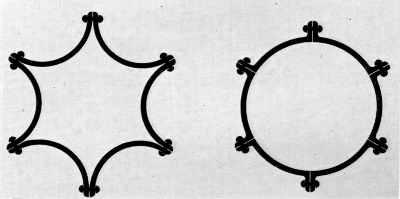
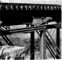
Figure 16.—Left: conjectural section of Bollman’s segmental wrought-iron column, about 1860, and section of the standard Phoenix column; right: Phoenix column as used in truss-bridge compression members.
EVALUATION OF THE TRUSS
By the late 1850’s iron was well established as a bridge material throughout the world. Once the previous fears of iron had been stilled and the attention of engineers was directed to the interpretation of existing and new spanning methods into metal, the Bollman truss began to suffer somewhat from the comparison. Although its components were simple to fabricate and its analysis and design were straightforward, it was less economical of material than the more conventional panel trusses such as the Pratt and Whipple types. Additionally, there was the requisite amount of secondary metal in lower chords and braces necessary for stability and rigidity.
A factor difficult to assess is Bollman’s handling of his patent, which was renewed in 1866. There is sufficient evidence to conclude that he considered the patent valuable because it was based upon a sound design. Therefore, he probably established a high license fee which, with the truss’s other shortcomings, was sufficient to discourage its use by other railroads. As patron, the B. & O. had naturally had full rights to its use.
An additional defect, acknowledged even by Bollman, arose because of the unequal length of the links in each group except the center one. This caused an unevenness in the thermal expansion and contraction of the framework, with the result that the bridges were difficult to keep in adjustment. This had the practical effect of virtually limiting the system to intermediate span lengths, up to about 150 feet. For longer spans the B. & O. employed the truss of another of Latrobe’s assistants, German-born and technically trained Albert Fink.
The Fink truss was evolved contemporaneously with Bollman’s and was structurally quite similar, being a suspension truss with no lower chord. The principal difference was the symmetry of Fink’s plan, which was achieved by carrying the individual panel loads from the panel points to increasingly longer panel units before having them appear at the end bearings. This eliminated the weakness of unequal strains. The design was basically a more rational one, and it came to be widely used in spans of up to 250 feet, generally as a deck-type truss (see fig. 11).
W. Bollman and Company
Bollman resigned from the Baltimore and Ohio in 1858 to form, with John H. Tegmeyer and John Clark, two of his former B. & O. assistants, a bridge-building firm in Baltimore known as W. Bollman and Company. This was apparently the first organization in the United States to design, fabricate, and erect iron bridges and structures, pioneering in what 25 years later had become an immense industry. The firm had its foundation at least as early as 1855 when advertisements to supply designs and estimates for Bollman bridges appeared over Tegmeyer’s name in several railroad journals (see fig. 12).
Bollman’s separation from the B. & O. was not a complete one. The railroad continued its program of replacing timber bridges with Bollman trusses, and contracted with W. Bollman and Company for design and a certain amount of fabrication. There is some likelihood that eventually fabrication was entirely discontinued at Mount Clair, and all parts subsequently purchased from Bollman.
The firm prospered, erecting a number of major railroad bridges in Mexico, Cuba, and Chile. Operations ceased from 1861 to 1863 because of difficult wartime conditions in the border city of Baltimore. Following this, Bollman reentered business as sole proprietor of the Patapsco Bridge and Iron Works.
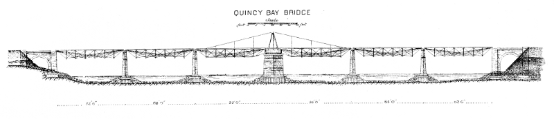
Figure 17.—Chicago, Burlington and Quincy Railroad bridge over Quincy Bay (branch of the Mississippi River) at Quincy, Illinois. The pivot draw-span was formed of two Bollman deck trusses supported at their outer ends by hog chains. The bridge was built in 1867-1868 by the Detroit Bridge and Iron Co., Bollman licensee. (Clarke, Account of the Iron Railway Bridge … at Quincy, Illinois.)
The most noteworthy of Bollman’s works in this period was a series of spans at Harpers Ferry. The B. & O.’s timber bridge had been destroyed by Confederate forces in June 1861, and the crossing was thereafter made upon temporary trestlework. This was a constant source of trouble, with continuing interruptions of the connection from high water, washouts, and military actions. The annoyance and expense of this became so great that the company decided to risk an iron bridge at the crossing. In July and August 1862, two sections of Bollman truss, spans no. 4 and no. 5 were completed. As this occurred during the time when W. Bollman and Company was inoperative, the work was produced at Mount Clair to Bollman’s design and, undoubtedly, erected under his supervision. Five weeks later, on September 24, these and Bollman’s famous Winchester span of 1851 were blown up by the Confederates, and the line’s business was again placed at the mercy of trestling.
The spirit of the B. & O. administration indeed seems to have been unshakable when, in the face of such heartbreaking setbacks, it determined to again bridge the river with iron, even at the height of the hostilities. In November, span no. 5 was erected, and by April 1863 nos. 3, 4, and 6 also. These were the four straight spans in midriver between the “wide” (or “branch,” or “wye”) span and the span on the Maryland shore over the Chesapeake and Ohio Canal (see fig. 13). Although the wood floor system of these spans was burned for strategic reasons by U.S. troops later in 1863, they survived the war.
In 1868 the remaining trestlework was replaced with Bollman trusses. This magnificent structure served the railroad until 1894 when the right-of-way was realigned at Harpers Ferry. However, the half used by the common road remained in use until carried away by the disastrous flood in 1936. The piers may still be seen.
During the prewar years, Bollman evolved a structural development of most profound importance, which is usually associated with the Phoenix Iron Works and its founder, Samuel J. Reeves. In the erection of a high trestlework viaduct for the Havana Railroad, Bollman apparently became concerned with the tensile weakness of cast iron when applied in long, unsupported columns. Although a column is normally subjected to compressive stresses, when the slenderness ratio—that is, the length divided by the radius of gyration of the cross section—becomes great, a secondary bending stress may be produced. If this stress becomes great enough, the value of the tensile stress in one side of the column may actually exceed the principal compressive stress, and a net effect of tension result.
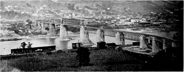
Figure 18.—Ohio River crossing of the Baltimore and Ohio at Benwood, West Virginia, completed in 1870. Bollman deck trusses were used in the approaches on both sides. (Photo 693, Baltimore and Ohio Collection, Museum of History and Technology.)
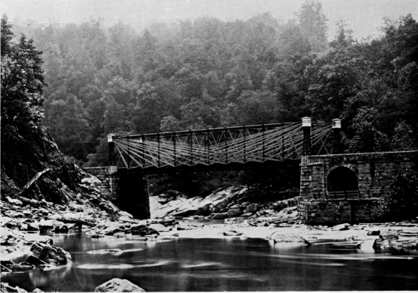
Figure 19.—Patapsco River crossing of the Baltimore and Ohio between Thistle and Ilchester, Maryland. (Photo 695, Baltimore and Ohio Collection, Museum of History and Technology.)
As already mentioned, the few available rolled-iron shapes were of relatively small area and quite unsuitable for use as columns unless combined and built up in complex fabrications. The normal practice at the time was to use cast compression members in iron bridges and structures, with their sectional area so proportioned to the length that a state of tension could not exist. In the case of long members, this naturally meant that an excessive amount of material was used.
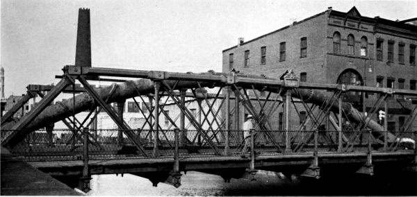
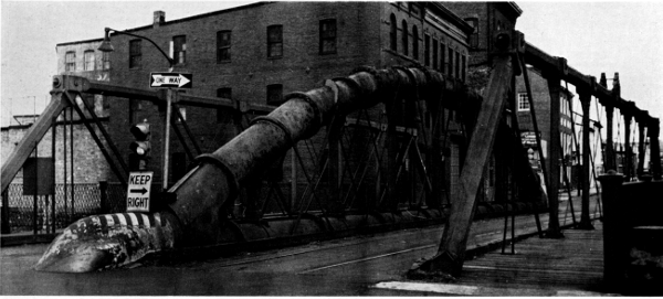
Figure 20.—Two views of Bollman-built “water-pipe truss” that carries Lombard Street over Jones Falls in Baltimore. Built in 1877.
Bollman was conscious of the problem from his experience with the stretchers and struts of his truss, and he must have been aware of the great advantage which would be obtained by a practical method of forming such members in wrought iron, the tensile resistance of which is equivalent to the compressive. He eventually developed the forerunner of what came to be known as the Phoenix form by having special segmental wrought-iron shapes rolled by Morris, Tasker and Company of Philadelphia, these shapes being combined into a circular section with out standing flanges for riveting together. The circular section is theoretically the most efficient to bear compressive loading. A column of any required diameter could be produced by simply increasing the number of segments, the individual size of which never exceeded contemporary rolling mill capacity (see fig. 16).
The design exhibits the inspired combination of functional perfection and simplicity that seems to characterize most great inventions.
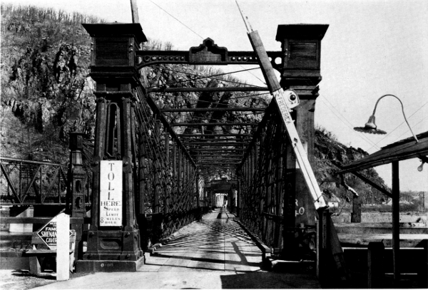
Figure 21.—The Harpers Ferry bridge toward the end of its career, carrying a common road over the Potomac. The westernmost line of trussing and span no. 1 had been removed long before. View through the Winchester span looking toward Maryland in 1933. (Photo courtesy of Harpers Ferry National Historical Park.)
It may have been because he had no facilities for rolling that Bollman communicated his idea to Reeves, although this seems illogical. At any rate, Reeves and his associates patented the system extensively, and the Phoenix column was eventually employed to the virtual exclusion of cast-iron and other types of wrought-iron columns. By the end of the 19th century it began to pass from use, as mills became capable of producing larger sections with properties relatively favorable to column use and more adaptable to connection with other members.
Final Use of the Bollman Truss
The Bollman truss found occasional use elsewhere than on the B. & O. lines, but generally only when erected on contract by Patapsco Bridge and Iron Works. However, the fact that Bollman could profitably erect this bridge in the severely competitive 1870’s indicates that the harsh criticism of the system by authorities of such stature as Whipple was not necessarily justified. Bollman’s advertisements, in fact, refer to the favorable recommendations of other such renowned engineers as Herman Haupt and M. C. Meigs.
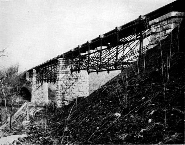
Figure 22.—Bollman deck trusses in the North River Bridge built in 1873 at Mount Crawford, Virginia, on the Valley Railroad of Virginia (B. & O.). Each end span is 98 ft. 6 in.; the river span is 148 ft. 9 in. (Photo 756, Baltimore and Ohio Collection, Museum of History and Technology.)
An interesting application of the system was in a drawbridge, formed of two Bollman deck spans, over an arm of the Mississippi at Quincy, Illinois (see fig. 17). The first iron bridge in Mexico was erected by Bollman over the Medellín River about 1864. Another work of this period, which attracted considerable attention, was a pair of bridges that Bollman erected over North Carolina’s Cape Fear River in 1867-1868. These bridges were notable for their foundation on cast-iron cylinders, sunk pneumatically. This was one of the first instances of the use of the process in America, and the depth of 80 feet below the water surface reached by one cylinder was considered remarkable for years afterward.
In the last active decade or so of his career, Bollman produced hundreds of minor bridges and other structures. In 1873 he supplied the castings for the splendid iron dome of Baltimore’s City Hall and erected the ingenious water-main truss which carries Lombard Street over Jones Falls in that city. In this structure the top and bottom chords of the central line of trussing are cast-iron water mains, bifurcated at the abutments, and joined by cast- and wrought-iron web members (see fig. 20).
In the mid 1870’s Bollman saw his truss pass into obsolescence. This was due primarily to the generally increasing distrust of cast iron for major structural members due to its brittleness, but advances in structural theory, availability of a greater variety of rolled structural shapes, and the increasing loading patterns of the period all contributed.
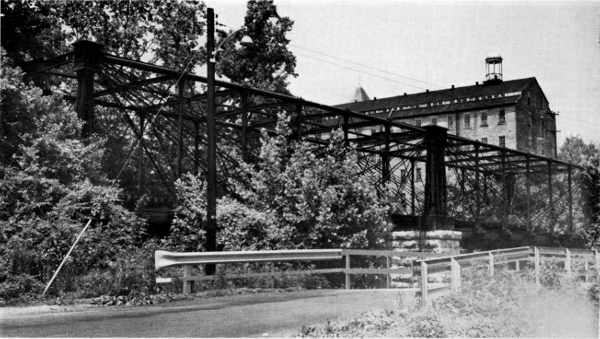
Figure 23.—The only surviving Bollman truss bridge, at Savage, Maryland. The bridge was built elsewhere in 1852 and was moved to this now-abandoned Baltimore and Ohio industrial siding in about 1888.
Although no Bollman trusses were built by Bollman or the B. & O. after 1875, those in use were only removed as required by heavier motive power. The Harpers Ferry span, as noted, remained in full main-line service until 1894. Bollman trusses on feeder lines were continued in use until much later; a number of them on the Valley Railroad of Virginia (see fig. 22) were not removed until 1923. However, only on the most isolated spurs was the Bollman truss permitted to reach really ripe age. The sole known remaining example (fig. 23) stands on such a branch—ironically, at Savage, over the Little Patuxent, the site of the first Bollman span. This is not the 1850 bridge, but one built in 1852 and moved to the present site 30 years later. The fate of the first span is not known.
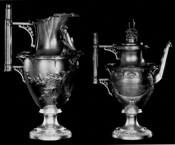
Figure 24.—Hot-water and chocolate pitchers of the 10-piece, silver tea service presented to Bollman by his fellow employees when he resigned from the Baltimore and Ohio in 1858. A railroad motif was used throughout, each piece being circled at top and bottom by a track, complete with rail of accurate section and ties. Spouts are in simulation of hexagonal sheet-iron chimneys, with seams riveted, and the handles are in the form of a surveyor’s telescope. On the various pieces are engraved the designs of the more important B. & O. bridges. Throughout is a wonderful profusion of bits and objects of railroadiana in low relief, high relief, and fully modeled. In Board of Directors Room, Baltimore and Ohio Railroad Company, Baltimore, Md. (Photo courtesy of Baltimore and Ohio Railroad.)
Known Bollman Works
(All B. & O. works listed were designed by Bollman and built by the railroad, unless otherwise indicated.)
Dates of service Location Type No. spans / length of each Remarks
1850-? Savage, Md., Little Patuxent River Bollman through truss 1/76' First Bollman truss erected; granite towers; cost, $23,825. B. & O. RR.
1851-? Bladensburg, Md., Anacostia River Bollman through truss 1/? Second Bollman truss erected; granite towers; cost, $19,430. B. & O. RR.
1851-1862 Harpers Ferry, Va., Potomac River Bollman through truss 1/124' Winchester span; first major Bollman truss; three lines of truss; granite towers; blown up by Confederate Army on September 24, 1862. B. & O. RR.
1851-? Baltimore, Md., Carey Street Trestle — Wood trestle bents with wrought-iron diagonals. First use of iron structural members in trestlework. Total length 76 feet. B. & O. RR.
1852- Savage, Md., Little Patuxent River Bollman through truss 2/?80' Still standing. Moved to Savage in 1888; original location unknown. This and succeeding Bollman trusses use iron towers. B. & O. RR.
1852 (or 1853)-? Marriottsville, Md., Patapsco River Bollman truss 1/50' One of first Bollman trusses with iron towers. B. & O. RR.
1853-? Zanesville, Ohio, Muskingum River Bollman truss 4/124' (or 5/160') Double track, Central Ohio RR. Designed by Bollman; built by Douglas, Smith & Co., Zanesville.
1854-1870(?) Elysville (now Daniels), Md., Patapsco River Bollman through truss 3/97'9" Upper bridge, skew. Cost, $24,477.59. B. & O. RR.
1854-1862 Monocacy, Md., Monocacy River Bollman truss 3/119' Blown up September 8, 1862; rebuilt in 1864. Cost, $22,722.59. B. & O. RR.
1854-? Eastern Ohio Bollman truss(?) 1/40' C. O. RR. Section 76 adjacent to 300-ft. tunnel.
1855-? Bridgeville, Ohio, Salt Creek Bollman deck truss 1/71' C. O. RR.
Pre-1855-? Buffalo, N.Y. — — Unidentified. Mentioned by George Vose in Railroad Advocate (June 9, 1855).
1856-? Elysville, Md., about 11/4 miles east of 1854 bridge, Patapsco River Bollman through truss 3/111' Lower Bridge. B. & O. RR.
Pre-1856-? Marriottsville, Md. Bollman truss(?) 1/48'9" Referred to as “Tunnel Bridge” in B. & O. RR. annual report, 1856.
1856-? Near Ijamsville, Md., Bush Creek Iron girders 3/23'9" Possibly trussed beams; mentioned in B. & O. RR. annual report, 1856.
1856-? Near Ijamsville, Md., Bush Creek Iron girders 2/23'9" As above.
1856-c.1862 North Branch, Md., Potomac River Bollman deck truss 3/142' Partially destroyed in Civil War. B. & O. RR.
1860-1906 Chile, Angostura River Bollman truss(?) 4/115' Chilean Railways. Designed and built by Bollman. Replaced by bridge built by French firm of Schneider, Cruesot & Co.
1860-1910 Chile, Paine River Bollman truss(?) 1/? As above.
Post-1860-? Ilchester, Md., Patapsco River Bollman through truss 1/? B. & O. RR.
Pre-1861-? Cuba Bridges and station house — All bridges on Havana RR., including iron station house and bridge at Guines. Designed and built by Bollman.
Pre-1861-? Cuba Bridges — All bridges on Cienfuegos RR., Cárdenas RR., and Havana & Matanzas RR. Designed and built by Bollman.
Pre-1861-? Cuba Trestle — Trestle with wrought-iron columns (the first such ever constructed). Havana RR. Designed and built by Bollman.
1862-1862 Harpers Ferry, Va., Potomac River Bollman through truss 2/160' Span no. 3 (July 24) and span no. 4 (August 21). Blown up September 24, 1862. B. & O. RR.
1862-1936 Harpers Ferry, Va., Potomac River Bollman through truss 1/160' Span no. 5 (November). B. & O. RR.
1863-1936 Harpers Ferry, Va., Potomac River Bollman through truss 3/160' Spans nos. 3, 4, and 5. Constructed previous to April 1863. B. & O. RR.
1863-? Berwyn, Md., Paint Branch Bollman truss(?) ? Iron bridge mentioned in B. & O. RR. annual report, 1863
1863(4?)-? Clinton, Iowa, Mississippi River Pivot draw 1/360' Built by Detroit Bridge & Iron Works. It was the longest in the world at time of completion. Designed by Bollman.
1864-? Laurel, Md., Patuxent River Bollman truss ? Replaced stone arch that had been washed out. B. & O. RR.
c. 1864-? Near Veracruz, Mexico, Medellín River Bollman hrough truss 1/115' Veracruz & Jucaro RR. First iron bridge in Mexico. Designed and built by Bollman.
1864-? Near Point of Rocks, Md., Back Creek Bollman truss(?) 1/80'(?) Iron bridge mentioned in B. & O. RR. annual report, 1864. The span length given is that of previous stone arch.
1864-? Bladensburg, Md., Anacostia River Bollman truss 1/? Span for second track, to match 1851 span. B. & O. RR.
1868-? Cape Fear, N.C., Northeast Branch, Cape Fear River Bollman truss(?) 2/146'6" 1/164' pivot draw/150' Wilmington Railway Bridge Co. This bridge was connected to that over the Northwest Branch by 21/2 miles of timber trestling. Designed and built by Bollman.
1868-? Cape Fear, N.C., Northwest Branch, Cape Fear River Bollman truss(?) 1/217'(?) pivot draw/150' See above.
1868-? Quincy, Ill., Quincy Bay (in Mississippi River) Bollman deck truss 4/85' pivot draw/190' Chicago, Burlington & Quincy RR. The pivot draw was formed of two 85-ft. simple Bollman deck spans whose outer ends hung from hog chains. Designed by Bollman; built by Detroit Bridge & Iron Works.
1869-c.1892 Baltimore, Md., over Jones Falls, B. & O. RR., and Northern Central RR. Warren truss 2/100' 2/55'6" North Avenue Bridge. Composite double intersection truss; timber top chord and posts, wrought-iron lower chord and ties. In 55-ft. spans, both chords timber. Cost, $73,588. Built by Bollman.
c.1869-1936 Harpers Ferry, Va., Potomac River Bollman through truss 4/? Canal span (no. 8), Wide span (no. 2), Winchester span, and West End span. Destroyed by flood in 1936. B. & O. RR.
1870-.1895 Baltimore, Md., Jones Falls Iron “Isometrical truss” (probably Pratt type) 1/108' Charles Street Bridge. Three lines of trussing.Cost, $20,297. Built by Bollman.
1870-1893 & 1900 Bellaire, Ohio-Benwood W. Va., Ohio River Bollman deck truss 9/107'-125' In approaches; 2 spans on Ohio side; 7 on West Virginia side. B. & O. RR.
1870-c.1895 Belpre, Ohio-Parkersburg, W. Va., Ohio River Bollman deck truss 16/? In approaches; 7 spans on Ohio side; 9 on West Virginia side. B. & O. RR.
1870-? Elysville, Md., Patapsco River Bollman through truss 4/? Skew; replacement of Upper Bridge(?). B. & O. RR.
1871-c.1895 Baltimore, Md., Jones Falls Timber and iron truss ? Decker Street (now Maryland Avenue) Bridge. Cost, $24,975. Built by Bollman.
1871-c.1892 Baltimore, Md., over Northern Central RR. at Jones Falls Warren truss 1/100' North Avenue Bridge. Composite double intersection truss; cast-iron top chord and posts; wrought-iron bottom chord and ties. West span. Built by Bollman.
1873-1923 Cave Station, Va., Middle River Bollman deck truss 1/98'7" 1/63'5" Valley Railroad of Virginia (B. & O.) Bridge no. 120. The main span was a Whipple deck truss. Replaced with plate girders. Designed by Bollman.
1873-1923 Mount Crawford, Va., North River Bollman deck truss 2/98'6" 1/148'9" Valley Railroad of Virginia (B. & O.) Bridge no. 117. Designed by Bollman.
1873-1923 Verona, Va., North River Bollman deck truss 3/98'7" Valley Railroad of Virginia (B. & O.) Bridge no. 129. The main span was a 147-ft. Whipple deck truss. Designed by Bollman.
1873-? Wadesville, Va., Opequon Creek Bollman through truss 1/147'8" Span length given is that of previous wood span that burned in 1862. B. & O. RR.
c. 1873- Baltimore, Md. Iron roof trusses ? First Presbyterian Church. Built by Bollman; possibly designed by him.
1873- Baltimore, Md. Cast-iron stairs City Hall. Cost, $12,840. Designed by George A. Frederick, architect; built by Bollman.
1873- Baltimore, Md. Cast-iron framework Dome of the City Hall. Cost, $70,525. Designed by George A. Frederick; built by Bollman.
1875-c.1913 Baltimore, Md., Jones Falls Iron truss 1/? Fayette Street Bridge. Cost, $9,396. Built by Bollman.
1876-c.1913 Baltimore, Md., Jones Falls Single-beam iron bridge (truss?) 1/? Canton Avenue (now Fleet Street) Bridge. Cost, $8,904. Built by Bollman.
1876-c.1913 Baltimore, Md., Jones Falls Single-beam iron bridge (truss?) 1/? Eastern Avenue Bridge. Cost, $12,382. Built by Bollman.
1877- Baltimore, Md., Jones Falls Pratt and bowstring truss 1/88'6" Lombard Street Bridge. Three lines of truss; two outer trusses, composite cast- and wrought-iron polygonal Pratt type; center composite bowstring with Pratt-system web. Both chords are cast-iron water mains, bifurcated at the end bearings; cast-iron posts and wrought-iron ties. In service. Cost, $7,632. Designed by Jas. Curran, Baltimore water department; built by Bollman.
1877-c.1913 Baltimore, Md., Jones Falls Iron truss 1/? Bath Street Bridge. Cost, $4,172. Built by Bollman.
1879-? Baltimore, Md. Drawbridge 1/? Over entrance to City Dock. Cost, $13,182. Built by Bollman.
1879-c.1930 Baltimore, Md., over Jones Falls and railroad tracks Warren truss 2/173'9" North Street (now Guilford Avenue) Bridge. Composite trusses; cast-iron top chord and end posts; wrought-iron bottom chord and web members. Cost, $38,772.45. Built by Bollman; designed by Latrobe.
1881-1960 Baltimore, Md., (Woodberry), Jones Falls Wrought-iron Pratt truss 1/? Union Avenue Bridge. Built by Bollman; possibly designed by him.
?-? Harpers Ferry, Va., Arsenal Canal Bollman through truss 1/148' Arsenal Branch, B. & O. RR. Skew type. Span length is that of previous timber span.
?-? Baltimore, Md., Gwynns Falls Bollman through truss 2/? B. & O. RR.
BIBLIOGRAPHY
A history and description of the Baltimore and Ohio Railroad by a citizen of Baltimore. Baltimore, 1853.
Baltimore and Ohio Railroad Company. A list of the officers and employees of the Baltimore and Ohio Railroad for November, 1857. Baltimore, 1857.
——. Third annual report of the president and directors to the stockholders of the Baltimore and Ohio Rail Road Company. Baltimore: 1829. (Also the fourth through 38th annual reports. Baltimore, 1830-1864.)
——. Baltimore and Ohio exhibits at the Century of Progress. Chicago, 1934.
Biographical cyclopedia of representative men of Maryland and the District of Columbia. Baltimore, 1879.
Bollman, Wendel. Iron suspension and trussed bridge as constructed for the Baltimore and Ohio Rail Road Co. at Harper’s Ferry, and on the Washington branch of this road. Baltimore, 1852.
——. Letter to John W. Garrett dated June 17, 1862. In files of Division of Mechanical and Civil Engineering, United States National Museum, Washington, D.C.
——. Report of Mr. Bollman in relation to Central Ohio Rail Road. Baltimore, 1854.
Bryant, William C. Picturesque America. New York, 1874.
Clarke, Thomas Curtis. An account of the iron railway bridge across the Mississippi River at Quincy, Illinois. New York, 1869.
Colburn, Zerah. American iron bridges. Minutes of the proceedings of the Institution of Mechanical Engineers (1863), vol. 22, pp. 540-573.
Condit, Carl. American building art:—The nineteenth century. New York: Oxford Press, 1960.
Gray, George E. Notes on early practice in bridge building. Transactions of the American Society of Civil Engineers (1897), vol. 37, pp. 2-16.
Greiner, John E. The American railroad viaduct—Its origin and evolution. Transactions of the American Society of Civil Engineers (1891), vol. 25, pp. 349-372.
Lang, Philip George. Bollman trusses on Valley of Virginia Branch will soon be memories. Baltimore and Ohio Magazine (October 1923), pp. 18-19.
——. The old Baltimore and Ohio bridge crossing the Potomac River at Harpers Ferry, West [sic] Virginia. Engineering News-Record (September 17, 1931), p. 446.
Malezieux, Emile. Travaux publics des Etats-Unis d’Amerique en 1870. Paris, 1873.
McDowell, W. H. Unpublished engineer’s report to the president and directors of Wilmington Railway Bridge Company, Wilmington, North Carolina, dated March 12, 1868. Typewritten copy in files of Division of Mechanical and Civil Engineering, U.S. National Museum, Washington, D.C.
Smith, Charles Shaler. Comparative analysis of the Fink, Murphy, Bollman and triangular trusses. Baltimore, 1865.
Smith, William P. The book of the great railway celebrations of 1857. Baltimore, 1858.
Tyrrell, Henry G. History of bridge engineering. Chicago, 1911.
Whipple, Squire. Bridge building. Albany, New York, 1869.
Transcription of Figure 12 for screen readers.
WENDEL BOLLMAN’S Patent Iron Suspension Railroad Bridge.
The undersigned would inform the officers of Railroads and others, that he is prepared to furnish Drawings and Estimates for Bridges, Roofs, etc., on the plan of Bollman’s Patent.
The performance of these bridges, some of which have been in use for six years, has given entire satisfaction. Their simplicity of construction renders repairs easy and cheap, and by a peculiar connection of the Main and Panel Rods at the bottom of the Posts, all danger from the effects of expansion, which has heretofore been the chief objection to Iron Bridges, is entirely removed.
J. H. TEGMEYER, Baltimore, Md.
Paper 36 - Transcriber’s Note
Inconsistencies in punctuation have been corrected without note. Inconsistent hyphenation is as per the original.
Contributions from The Museum of History and Technology: Paper 37 Screw-Thread Cutting by the Master-Screw Method Since 1480
Edwin A. Battison
Edwin A. Battison
SCREW-THREAD CUTTING BY THE MASTER-SCREW METHOD SINCE 1480
Among the earliest known examples of screw-thread cutting machines are the screw-cutting lathe of 1483, known only in pictures and drawings, and an instrument of the traverse-spindle variety for threading metal, now in the Smithsonian Institution, dating from the late 17th or early 18th century. The author shows clearly their evolution from something quite specialized to the present-day tool. He has traced the patents for these instruments through the early 1930’s and from this research we see the part played by such devices in the development of the machine-tool industry.
The Author: Edwin A. Battison is associate curator of mechanical and civil engineering in the Smithsonian Institution’s Museum of History and Technology.
Directness and simplicity characterize pioneer machine tools because they were intended to accomplish some quite specialized task and the need for versatility was not apparent. History does not reveal the earliest forms of any primitive machines nor does it reveal much about the various early stages in evolution toward more complex types. At best we have discovered and dated certain developments as existing in particular areas. Whether these forms were new at the time they were first found or how widely dispersed such forms may have been is unknown. Surviving evidence is in the form of pictures or drawings, such as the little-known screw-cutting lathe of 1483 (fig. 1) shown in Das mittelalterliche Hausbuch.
This lathe shows that its builder had a keen perception of the necessary elements, reduced to bare essentials, required to accomplish the object. Present are the coordinate slides often credited to Henry Maudslay. His slides are not, of course, associated with the spindle; neither is there any natural law which compels them to guide the tool exactly parallel with the axis of revolution. In this sense the screw-cutting lathe in the Hausbuch is superior because it is in harmony with natural law and can generate a true cylinder, whereas Maudslay’s lathe can only transfer to the work whatever accuracy is built into it.
In principle this machine shown in the Hausbuch is very advanced as we see when we follow the design through to the present time. The artist, whose drawings give us our only knowledge of the machine, himself was obviously not very familiar with the details of its function. Reference to figure 1 shows that the threads on the lead screw and on the work, wind in opposite directions. This must be an error in delineation since the two are closely coupled together without any intervening mechanism so that the only possible result on the work must be a thread winding in the same direction as on the original screw. The work also is shown threaded for its entire length; this cannot be accomplished with any one location of the cross-slide. We are left with the question of whether this slide was used in two locations or whether the artist, possibly working from notes or an earlier rough sketch, failed to show an unthreaded portion on one end or the other of the work.
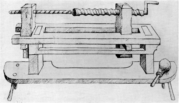
Figure 1.—Earliest representation found of a master-screw type of thread-cutting machine. From the inconsistencies, such as right- and left-hand threads on master and work, it appears that the artist had scant insight into actual function. From plate 62 of Das mittelalterliche Hausbuch, nach dem Originale im Besitze des Fürsten von Waldburg-Wolfegg-Waldsee, im Auftrage des Deutschen Vereins für Kunstwissenschaft, herausgegeben von Helmuth Th. Bossert und Willy F. Storck (Leipzig: E. A. Seemann, 1912).
Of at least equal importance with the lead screw and work and their relationship to each other is the tool-support with its screw-adjusted cross-slide (fig. 2). Just how this was attached to the frame of the machine so that it placed the tool at a suitable radius is again a questionable point. The very well-developed cutting tool is sharpened to a thin, keen edge totally unsuited for cutting metal but ideal for use on a softer, fibrous substance: undoubtedly wood, in this instance. Unfortunately, the angle at which the artist chose to show us this cutter is not a view from which it is possible to judge whether or not the tool has been made to conform to the helix angle of the thread to be cut. This cross-slide, in conjunction with the traversing work spindle, gives us a machine having two coordinate slides yielding the same effect as the slide rest usually attributed to Henry Maudslay at the end of the 18th century. Actually, an illustration of coordinate slides independent of the spindle had been published as early as 1569 by Besson [1] and knowledge of them widely disseminated by his popular work on mechanics. These slides are shown as part of a screw-cutting machine with a questionably adequate connection, by means of cords, between the master screw and the work.
It was the author’s pleasure recently to obtain for the Smithsonian Institution and identify a small, nicely made, brass instrument which had been in two collections in this country and one collection in Germany as an unidentified locksmith’s tool (fig. 3). This proved to be an instrument of the traverse-spindle variety for threading metal. Fortunately, all essential details were present including a cutter (A in figure 4); this instrument was identified by the signature “Manuel Wetschgi, Augspurg.” The Wetschgis were a well-known family of gunsmiths and mechanics in Augsburg through several generations. Two bore the given name Emanuel: the earlier was born in 1678 and died in 1728. He was quite celebrated in his field of rifle making and became chief of artillery to the Landgrave of Hesse-Kassel shortly before his death in his 51st year. Little is known of the later Emanuel Wetschgi except that he was at Augsburg in 1740. Tentative attribution of the instrument has been made to the earlier Emanuel, chiefly on the basis of his recognized position as an outstanding craftsman.
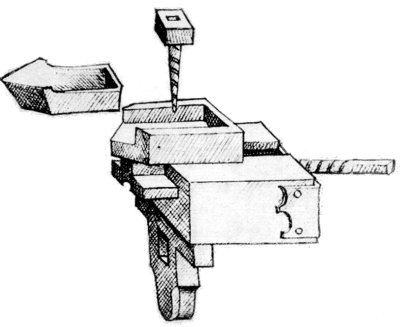
Figure 2.—Cross-slide for the thread-cutting lathe of Das mittelalterliche Hausbuch, shown in figure 1. It is remarkable not only for its early date, but also for its high state of development with a crossfeed screw which had not become universally accepted 300 years later. The cutter, shown out of its socket, is obviously sharpened for use on wood.
In several respects this little machine differs from its predecessor of the Hausbuch, as might be expected when allowance is made for the generations of craftsmen who undoubtedly worked with such tools over the roughly 200 years of time separating them. Another factor to consider when comparing these two machines is that one was used on metal, the other probably only on wood. Therefore, it is not surprising to find on the later machine an outboard or “tailstock” support for the work. The spindle of this support has to travel in unison with the work-driving spindle so that it is not an unexpected discovery to find that it is spring-loaded. Figure 5 shows how this spring may be adjusted to accommodate various lengths of work by moving the attachment screw to various holes in both the spring and in the frame. Also visible in the same illustration is a rectangular projection at the other end of the spring which engages a mating hole in the “tailstock” spindle to prevent its rotation.
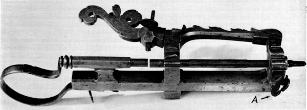
Figure 3.—Small thread-cutting lathe which was made to be held in a vise during use. It was found as shown here, with only the operating crank missing. The overall length is approximately 12 inches, depending on the adjustment of parts. (Smithsonian photo 46525B.)
Figure 6 shows the traversing spindle and nut removed from the machine. Provision has been made for doing this so easily that there is every reason to believe that, originally, there were various different spindle and nut units which could be interchangeably used in the machine. Additional evidence tending to support this concept exists in the cutting tool (fig. 4), which must have been intended for serious work as it has been carefully fitted in its unsymmetrical socket. The cutting blade of this tool, which works with a scraping rather than a true cutting action, is too wide to form a properly proportioned thread when used with the existing lead screw. This may well indicate that the tool was made for use with a lead of coarser pitch, now lost.
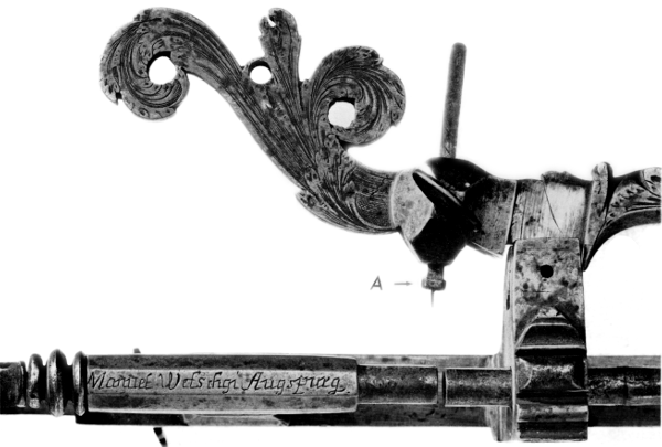
Figure 4.—The working area of figure 3, showing the tool and signature. (Smithsonian photo 46525A.)
Perhaps the most startling feature of this machine when compared with the machine of the Hausbuch, is the absence of a cross-slide for adjusting the tool. Possibly this can be explained by the blunt scraping edge on the tool. In actual use, recently, to cut a sample screw, using a tool similar to the one found in the machine (fig. 7), it was found advantageous to be free of a cross-slide and thus be able to feed the tool into the work by feel rather than by rule, as would be done with a slide rest. In this way, it was possible to thread steel without tearing, as the cutting pressure could readily be felt and the tool could release itself from too heavy a cut. Size on several screws could be repeated by setting the tool to produce the desired diameter when its supporting arm came to rest against the frame of the machine. The screws used in the machine itself were apparently made in just such a way. They were not cut with a die as the thread blends very gradually into the body of the screw without the characteristic marks left by the cutting edges of a die. Threads cut with a single-point tool controlled by a cross-slide usually end even more abruptly than those cut by a die, while it would be quite simple with a machine of the nature we are considering to bring the thread to a gentle tapering end as seen in figure 8 (another view of the screw A in fig. 3) by gradually releasing the pressure necessary to keep the tool cutting as the end of the thread was approached.
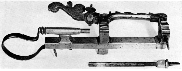
Figure 5.—Spring for keeping the follower spindle against the work, showing the method and range of adjustment. Note the rectangular projection to engage a mating socket in the spindle, to prevent spindle rotation. (Smithsonian photo 46525.)
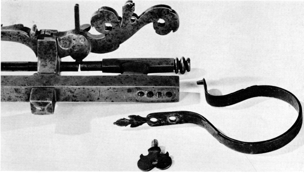
Figure 6.—Work spindle and its nut removed from the machine to illustrate how easily another spindle and nut of different pitch could be substituted. (Smithsonian photo 46525C.)
That machines of this general type having the lead screw on the axis of the work were competitive with other methods and other types of machines over a long period of time may be seen from figures 9 and 10. The machine, left front in figure 9 and in more intimate detail in figure 10, can be seen to differ little from that shown in Das mittelalterliche Hausbuch of 1483. The double work-support is, of course, a great improvement, while the tool-support is regressive since it lacks a feed screw.
The development of engineering theory, coupled with the rising needs of industry, particularly with the advent of the Industrial Revolution, brought about accelerated development of screw-cutting lathes through the combination of screw-cutting machines with simple lathes as seen in figure 9 and in detail in figure 11. One important advance shown here is driving the machine by means of a cord or band so that any means of rotary power could be applied, not just hand or foot power. Of greater interest and technical importance to this study is the provision, seen to better advantage in figure 11, for readily changing from one master lead screw to another. This had already been achieved in the Manuel Wetschgi machine, as far as versatility is concerned, although not in quite such a convenient way.
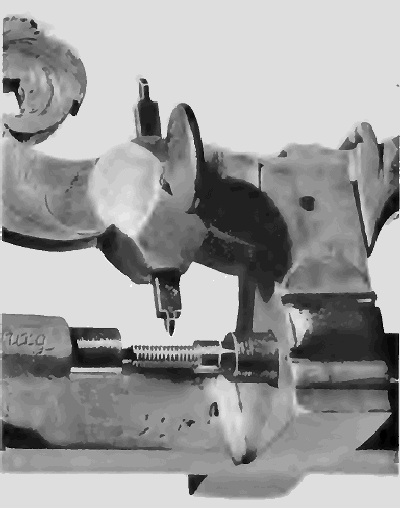
Figure 7.—Thread of modern form recently cut, using the old screw and nut but with a new tool. The material threaded is carbon-steel drill rod. (Smithsonian photo 49276A.)
Figure 12, the headstock of another and more advanced lathe than shown in figures 9 and 11 but of the same type, shows “keys” (D), each of which is a partial nut of different pitch to engage with a thread of mating pitch. The dotted lines in figure 13 show the engaged and disengaged positions of one of these keys, and figure 14 shows the spindle with the various leads, C. At D is a grooved collar to be engaged by the narrow key shown in operating position at the left in figure 12 for the purpose of controlling the endwise movement of the spindle when used for ordinary turning instead of thread-cutting. In return for greater convenience and freedom from the expense of the many separate spindles, as typified by the Wetschgi machine, a sacrifice has been made in the length of the thread which can be cut without interruption.
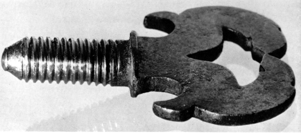
Figure 8.—Binding screw seen at A in figure 3, showing the long smooth fadeout of the thread below the shoulder. (Smithsonian photo 49276.)
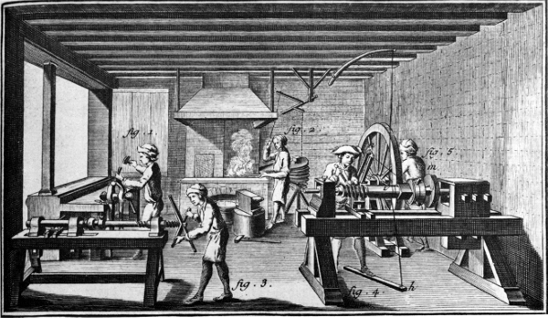
Figure 9.—Making screws in France in the third quarter of the 18th century. From L’Encyclopédie, ou dictionnaire raisonné des sciences, des arts et des métiers … receuil de planches sur les sciences, les arts libéraux, et les arts méchaniques, avec leur explication (Paris: 1762-1772), vol. 9, plate 1.
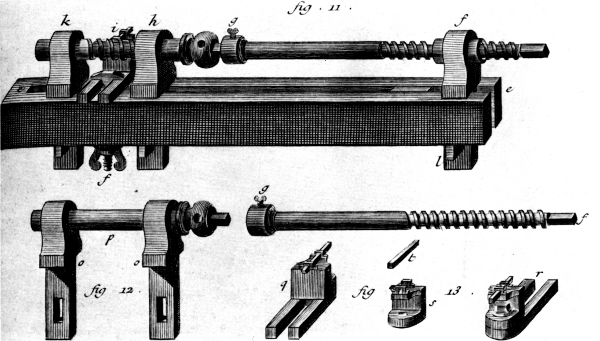
Figure 10.—Details of the machine in the left foreground of figure 9, showing the crude tool-support without screw adjustment. From L’Encyclopédie, vol. 9, plate 2.
This reduction in the length that could conveniently be threaded was no great drawback on many classes of work. This can be realized from figure 16 which shows a traverse-spindle lathe headstock typical of the mid-19th century. During the years intervening between the machines of figures 12 and 16, the general design was greatly improved by removing the lead screws from the center of the spindle. This made possible a shorter, much stiffer spindle and supported both ends of the spindle in one frame or headstock rather than in separate pieces attached to the bed. The screws were now mounted outside of the spindle-bearings, one at a time, while the mating nuts were cut partially into the circumference of a disk which could be turned to bring any particular nut into working position as required. With this arrangement, a wide variety of leads either right or left hand could be provided and additional leads could be fitted at any future time. Screw-cutting lathes of this design were popular for a very long time with instrument makers and opticians who had little need to cut screws of great length.
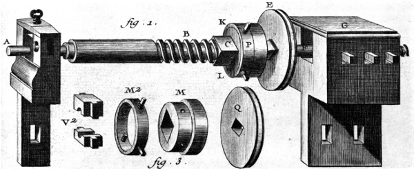
Figure 11.—Details of the threading lathe seen in the right foreground of figure 9 showing the method of drive and support for the work. From L’Encyclopédie, vol. 9, plate 1.
The demands of expanding industry for greater versatility in the production of engineering elements late in the 18th century set the stage for the evolution of more complex machines tending to place the threaded spindle lathes in eclipse. Maudslay’s lathe of 1797-1800 (fig. 15) appeared at this time when industry was receptive to rapid innovation. Unfortunately, the gearing which once existed to connect the headstock spindle with the lead screw has long been lost. At this time it is quite difficult to say with certainty whether the original gear set offered a variety of ratios, as was true of slightly later Maudslay lathes, or a fixed ratio. The plausibility of the fixed ratio theory is supported by the very convenient means, seen in figure 15, for removing the lead screw in preparation for substitution of one of another pitch. All that is required is to back off its supporting center at the tailstock end and withdraw the screw from its split nut [2] and from the driving clutch near the headstock. This split nut also would have to be changed to one of a pitch corresponding to that of the screw. While more expensive than a solid nut, it neatly circumvents the need (and saves the time involved) to reverse the screw in order to get the tool back to the point of beginning preliminary to taking another cut. David Wilkinson’s lathe of 1798 (fig. 17) which was developed in Rhode Island at the same time shows the same method of mounting and driving the master screw. At least in the United States, this method of changing the lead screw instead of using change gears remained popular for many years. Examples of this changeable screw feature are to be found in the lathes constructed for the pump factory of W. & B. Douglas Company, Middletown, Connecticut, [3] in the 1830’s. Middletown, at that time one of the leading metal-working centers in one of the chief industrial States, had been for many years the site of the Simeon North arms factory which rivaled Whitney’s. In this atmosphere, it is reasonable to expect that machinery constructed by local mechanics, as was the custom in those days, would reflect the most accepted refinements in machine design.
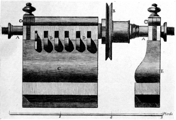
Figure 12.—Well-developed example of lathe headstock having several leads on the spindle and provision for mounting the work or a work-holding chuck on the spindle. Adapted from L’Encyclopédie, vol. 10, plate 13.
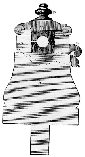
Figure 13.—End view of the headstock seen in figure 12, showing the keys or half nuts which engage the threaded spindle, in engaged and disengaged positions. From L’Encyclopédie, vol. 10, plate 13.
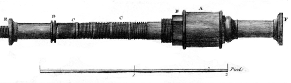
Figure 14.—Spindle of figures 12 and 13, showing the several leads and the many-sided seat for the driving pulley. Note the scale of feet. From L’Encyclopédie, vol. 10, plate 16.
Roughly twenty years later, Joseph Nason of New York patented [4] the commercially very important “Fox” brassworker’s lathe (fig. 18). While this does have a ratio in the pair of gears connecting the work spindle and master screw, it is clear from the patent that various pitches are to be obtained by changing screws, not by changing gears. The patent sums it up as follows:
A nut upon the end of the stud … is unscrewed when the guide screw is to be removed or changed. The two wheels … should have in their number of teeth a common multiple. They are seldom or never removed and their diameters are made dissimilar only for the purpose of giving to the guide screw a slower rate of motion than that of the mandrel whereby it may be made of coarser pitch than that of the screw to be cut and its wear materially lessened.
The introduction of gearing between the spindle and the lead screw, for whatever purpose, could not help but introduce variable factors caused by inaccuracies in the gears themselves and in their mounting. These were of little consequence for common work, particularly when coupled to a screw which, itself, was of questionable accuracy. The increasing refinements demanded in scientific instruments and in machine tools themselves after they had reached a relatively stable form dictated that attention be dedicated to improved accuracy of the threaded components.
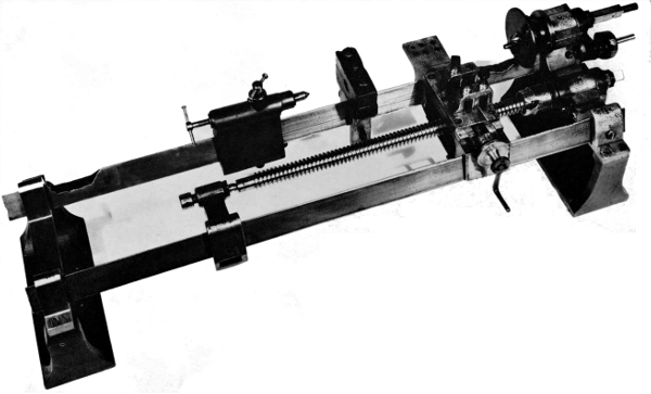
Figure 15.—Maudslay’s well-known screw-cutting lathe of 1797-1800, showing the method of mounting and driving changeable master screws. (Photo courtesy of The Science Museum, London.)
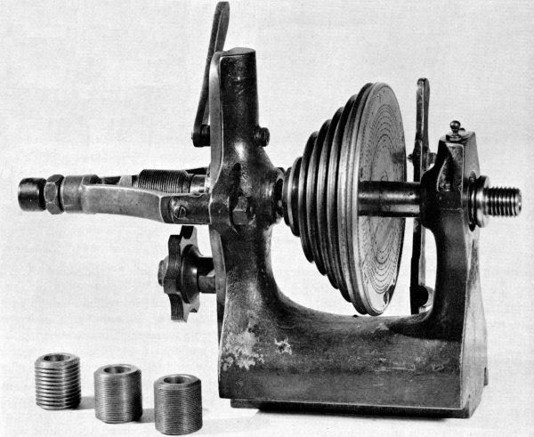
Figure 16.—Headstock of a German instrument-maker’s lathe, typical of the mid-19th century, showing the traverse spindle, interchangeable lead screws, and semicircumferential nut containing several leads. The nut may be brought into engagement by the lever at top rear of the headstock. This releases the end thrust control on the spindle simultaneously with engagement of the nut. (Smithsonian photo 49839.)
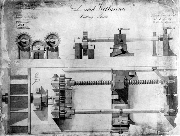
Figure 17.—David Wilkinson’s screw-cutting lathe, patented in the United States in 1798. Note the ready facility with which the lead screw may be exchanged for another and the same means of supporting and driving as in figure 15. (U.S. National Archives photo.)
An attack on this problem, which interestingly reverts to the fundamental principle of motion derived from a master screw without the intervention of other mechanism (fig. 19), is covered by a patent [5] issued to Charles Vander Woerd, one-time superintendent of the Waltham Watch Company. The problem is well stated in the patent:
This invention relates to the manufacture of leading screws to be used for purposes requiring the highest attainable degree of correctness in the cutting of the screw-threads of said screw … as, for example, in machines for ruling lines in glass plates to produce refraction [sic] gratings for the resolution of the lines of the solar spectrum, such machines being required to rule many thousands of lines on an inch of space by a marking device which is reciprocated over the glass plate and is fed by the action of a leading screw after the formation of each line. Great difficulty has been experienced in constructing a leading screw for this and other purposes, in which the thread is so nearly correct as to produce no perceptible variation in the microscopic spaces between the ruled lines or gratings…. Various causes prevent the formation of a thread on the rod or blank, which is absolutely uniform and accurate from end to end of the rod. Among other causes are the variations of temperature from time to time, the imperfections of the operating leading screw, the springing of the leading screw and of the rod that is being threaded, and other unavoidable causes, all of which, although apparently trivial and producing only slight variations in the thread at different parts of the rod or blank, are of sufficient moment to be seriously considered when a screw of absolute accuracy is desired.
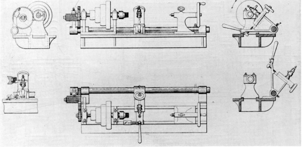
Figure 18.—Nason’s lathe, patented in 1854, showing a master lead screw driven at less than work speed so that the master could be of a coarser and more durable pitch than the work. U.S. patent 10383.
It is interesting to note in figure 19 that Vander Woerd’s machine, to avoid the problems outlined in his patent, has returned to a starkly simple design. We are not told, however, how he originated this master screw which is used to produce the accurately threaded work pieces. Later generations, in the search for ever-greater accuracy, also returned to the fundamental simplicity of a master screw as we shall see when we consider the refinements in mechanism necessary to the extended development of the automobile and the airplane.
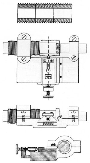
Figure 19.—Vander Woerd’s patent, seen here, covered the combination of a master screw, toolslide and work in a rigid frame to be supported and driven by outside means of no required precision. U.S. patent 293930 dated February 1884.
As the power and speed of automobiles and aircraft increased, critical parts became more highly stressed. Gears and threaded parts were particularly troublesome details of the mechanism because of the stresses concentrated in them, and, in the case of gears, because of the internal and external stresses originating in minute deviations from the ideal of tooth form and spacing. The problems were not entirely new but had hitherto been solved by increasing the size of the parts, an avenue of limited utility to designers in these fields where total weight as well as the effects of mass and inertia are so important. By making these parts of heat-treated steel, the strength could be made suitable while the size and mass of the parts were kept within bounds. The necessary processes of heat-treating were not always applicable to finished parts as they sometimes destroyed both finish and accuracy. Grinding, which was well developed for the simple plane, cylindrical, and conical surfaces so widely used in mechanisms, had to be extended to threads and gears so that they could be finished after heat-treating. Sometimes the gear teeth themselves were ground; for other applications it was sufficient to improve the accuracy of the gear cutters.
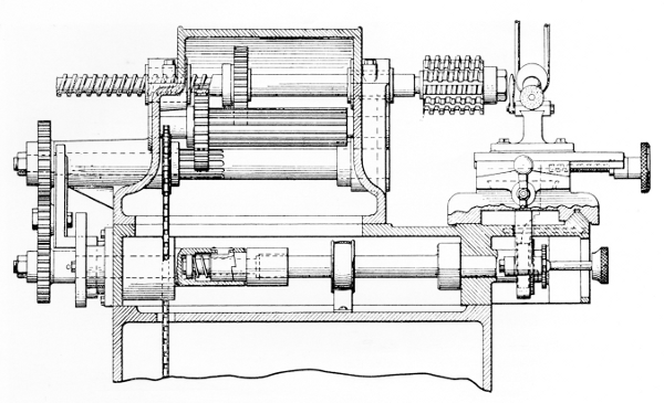
Figure 20.—A hob-grinding machine patented in 1932 and incorporating the master-screw principle. Carl G. Olson’s U.S. patent 1874592.
Attempts to produce gear hobs free of the imperfections and distortions introduced by heat treatment led to another return to the use of the master lead screw. Figure 20 illustrates a machine having this feature which was patented in 1932 by Carl G. Olson. [6] In speaking of the spindle-driving mechanism disclosed in earlier patents, the patent goes on to say:
This driving mechanism includes an integral spindle 20, one extremity thereof being designed for supporting a hob 22 and the other extremity thereof being formed so as to present a lead screw 24. The spindle 20 is mounted between a bearing 26 and a bearing 28, the latter bearing providing a nut in which the lead screw 24 rotates…. From the description thus far given it will be apparent that the rotation of the lead screw 24 within the bearing or nut 28 will cause the hob to be moved axially, the lead of the screw 24 being equal to the lead of the thread in the hob.
Claim 8 which concludes the descriptive portion of the patent states in part:
In a hob grinding machine of the class described, a rotary work supporting spindle, means for effecting longitudinal movement of the spindle, a tool holder for supporting a grinding wheel in operative position with respect to the work supported by the spindle during the rotary and longitudinal movement thereof, …
Even before this patent was applied for, another patent was pending for the purpose of modifying the pitch of the lead screw without the use of change gears in spite of the wide acceptance of such gear mechanisms for over a hundred years.
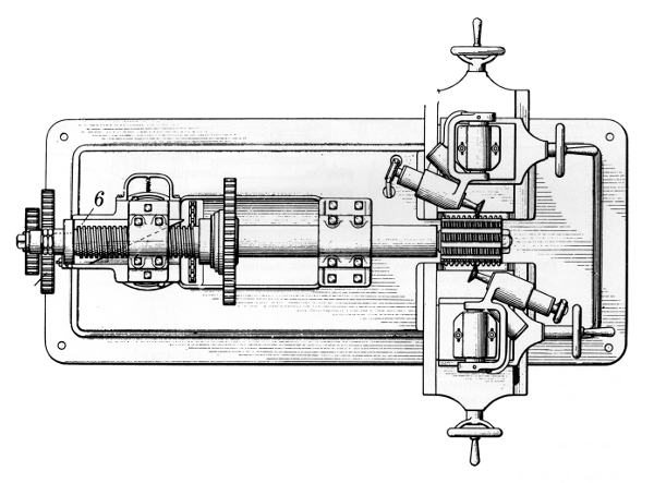
Figure 21.—A hob-grinding machine of 1933, showing use of the master screw with a modifier but without change gears. Carl G. Olson’s U.S. patent 1901926.
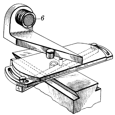
Figure 22.—A sine-bar device to modify the effective lead of a master lead screw without introducing a complex mechanism which would be both difficult to make and to operate within the required close limits. Carl G. Olson’s (1933) U.S. patent 1901926.
Figure 21 shows a plan view [7] of the machine, and figure 22 a detailed view of the sine-bar mechanism actuated by the master screw, 6, to modify the effective pitch of the lead screw in accordance with the realities of practice as stated in the preamble of the patent:
This invention relates to material working machines, and particularly to machines such as hob grinders and the like, wherein the work is reciprocated through the agency of a lead screw.
In the manufacture of hobs it is common practice to employ the same machine for grinding hobs of varied diameters, and in order to employ such a machine in this manner the pitch of the lead screw, thereof, which actuates the work carrier, must conform to the axial pitch of the hob to be ground. This will be readily apparent when it is understood that the helix angles of hobs vary in accordance with their diameters and, consequently, the difference between the normal pitch and the axial pitch correspondingly varies. While the requirement for the normal pitch may be the same for hobs of different diameters, it is necessary to change the axial pitch in accordance with a change in the hob diameter, and this axial pitch of the hob is equal to the pitch of the lead screw which actuates the work carrier in grinding machines heretofore used. Hence, in order to adapt such machines to cover a wide range of leads, it is necessary to provide a large number of interchangeable lead screws and obviously this represents a large investment, and the interchanging of these screws requires the expenditure of considerable time in setting up the machine for each job.
Thread-grinding machines were being designed concurrent with the development of hob-grinding machines. Many were entirely concerned with features peculiar to the problems of wheel-dressing and to automatic characteristics. An invention to embody the use of a master screw and concerned with the precision grinding of worm threads, for use in gearing, was patented by Frederick A. Ward in this era. [8] That part of the invention pertaining to the use of a master screw, “a rotary work holder mounted on said carriage and provided with a driving spindle, an exchangeable master screw and stationary nut detachably secured to said spindle and head, …” is shown in figure 23.
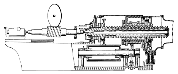
Figure 23.—Details of a work spindle with work, showing the use of a master lead screw to control the pitch of a precision worm thread being ground. From the 1933 U.S. patent 1899654, of F. A. Ward’s worm-grinding machine.
Machines embodying the principle of the master lead screw are found in constant use by industry at the present time for specialized application. Whenever technological changes again reopen the topic of thread-cutting to a new degree of accuracy or call for a reevaluation of popular methods for any other reason, we may expect to see another resurgence of the master-screw method, for no other design eliminates so many variables or rests on such firm and fundamental natural principles as the machine of Das mittelalterliche Hausbuch of 1483, the earliest such machine now known.
Paper 37 - Transcriber’s Note
Page 110: “… the spindle, to prevent …” (had “pindle”)
Page 120: “… servants à l'intelligence de plusieurs choses difficiles, & nécessaires …” (had “a,” “plusiers,” “necessaires”)
Produced by Chris Curnow, Joseph Cooper, Louise Pattison and the Online Distributed Proofreading Team at http://www.pgdp.net
"> Contributions from The Museum of History and Technology: Paper 38 The Earliest Electromagnetic Instruments
Robert A. Chipman
ELECTROSTATIC INSTRUMENTS BEFORE 1800 123
INSTRUMENTING VOLTAIC OR GALVANIC ELECTRICITY, 1800-1820 124
ELECTRICAL INSTRUMENTATION, 1800-1820 125
OERSTED’S DISCOVERY 126
BEGINNINGS OF ELECTROMAGNETIC INSTRUMENTATION 126
CHRONOLOGY AND PRIORITY 127
ORIGINAL ELECTROMAGNETIC MULTIPLIERS 129
CONCLUSIONS 135
ACKNOWLEDGMENTS 136
INDEX
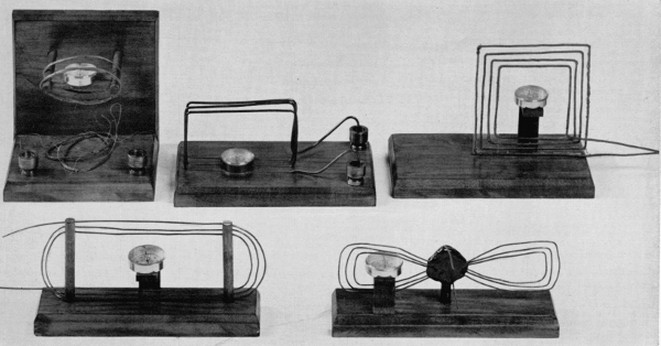
Figure 1.—Models of various electromagnetic instruments created by Schweigger, Poggendorf and Cumming in 1821, made for an exhibit in the Museum of History and Technology, Smithsonian Institution. (Smithsonian photo 49493.)
Robert A. Chipman
THE EARLIEST ELECTROMAGNETIC INSTRUMENTS
The history of the early stages of electromagnetic instrumentation is traced here through the men who devised the theories and constructed the instruments.
Despite the many uses made of voltaic cells after Volta’s announcement of his “pile” invention in 1800, two decades passed before Oersted discovered the magnetic effects of a voltaic circuit. As a result of this and within a five-month period, three men, apparently independently, announced the invention of the “first” electromagnetic instrument. This article details the merits of their claims to priority.
The Author: Robert A. Chipman is chairman of the Department of Electrical Engineering at the University of Toledo in Toledo, Ohio, and consultant to the Smithsonian Institution.
Electrostatic Instruments before 1800
It is the fundamental premise of instrument-science that a device for detecting or measuring a physical quantity can be based on any phenomenon associated with that physical quantity. Although the instrumentation of electrostatics in the 18th century, for example, relied mainly on the phenomena of attraction and repulsion and the ubiquitous sparks and other luminosities of frictional electricity, even the physiological sensation of electric shock was exploited semiquantitatively by Henry Cavendish in his well-known anticipation of Ohm’s researches. Likewise, Volta in 1800 [1] described at length how the application of his pile to suitably placed electrodes on the eyelids, on the tongue, or in the ear, caused stimulation of the senses of sight, taste and hearing; on the other hand, he reported that electrodes in the nose merely produced a “more or less painful” pricking feeling, with no impression of smell. The discharges from the Leyden jars of some of the bigger frictional machines, such as van Marum’s at Leyden, were found by 1785 to magnetize pieces of iron and to melt long pieces of metal wire. [2]
The useful instruments that emerged from all of this experience were various deflecting “electrometers” and “electroscopes” (the words were not carefully distinguished in use), including the important goldleaf electroscope ascribed to Abraham Bennet in 1787. [3]
In 1786, Galvani first observed the twitching of the legs of a dissected frog produced by discharges of a nearby electrostatic machine, thereby revealing still another “effect” of electricity. He then discovered that certain arrangements of metals in contact with the frog nerves produced the same twitching, implying something electrical in the frog-metal situation as a whole. Although Galvani and his nephew Aldini drew from these experiments erroneous conclusions involving “animal electricity,” which were disputed by Volta in his metal-contact theory, it is significant from the instrumentation point of view that the frog’s legs were unquestionably by far the most sensitive detector of metal-contact electrical effects available at the time. Without their intervention the development of this entire subject-area, including the creation of chemical cells, might have been delayed many years. Volta himself realized that the crucial test between his theory and that of Galvani required confirming the existence of metal-contact electricity by some electrical but nonphysiological detector. He performed this test successfully with an electroscope, using the “condensing” technique he had invented more than a decade earlier.
Instrumenting Voltaic or Galvanic Electricity, 1800-1820
In his famous letter of March 20, 1800, written in French from Como, Italy, to the president of the Royal Society in London, Volta made the first public announcement of both his “pile” (the first English translator used the word “column”), and his “crown of cups” (the same translator used “chain of cups” for Volta’s “couronne de tasses”). The former consisted of a vertical pile of circular disks, in which the sequence copper-zinc-pasteboard, was repeated 10 or 20 or even as many as 60 times, the pasteboard being moistened with salt water. The “crown of cups” could be most conveniently made with drinking glasses, said Volta, with separated inch-square plates of copper and zinc in salt water in each glass, the copper sheet in one glass being joined by some intermediate conductor and soldered joints to the zinc in the next glass.
Volta considered the “crown of cups” and the “pile” to be essentially identical, and as evidences of the electrical nature of the latter, said:
… if it contains about 20 of these stories or couples of metal, it will be capable not only of emitting signs of electricity by Cavallo’s electrometer, assisted by a condenser, beyond 10° or 15°, and of charging this condenser by mere contact so as to make it emit a spark, etc., but of giving to the fingers with which its extremities (the bottom and top of the column) have been touched several small shocks, more or less frequent, according as the touching has been repeated. Each of these shocks has a perfect resemblance to that slight shock experienced from a Leyden flask weakly charged, or a battery still more weakly charged, or a torpedo in an exceedingly languishing state, which imitates still better the effects of my apparatus by the series of repeated shocks which it can continually communicate. [4]
The “effects” provided by Volta’s pile and crown-of-cups are therefore electroscope deflection, sparks, and shocks. Later in the letter, he describes the stimulation of sight, taste, and hearing as noted earlier, but nowhere does he mention chemical phenomena of any kind, or the heating of a wire joining the terminals of either device. Hence, except for the additional physiological responses, he adds nothing to the catalog of observations on which instruments might be based. His familiarity with the moods of the torpedo (electric eel) seems to be intimate.
The reading of Volta’s letter to the Royal Society on June 26, 1800, its publication in the Society’s Philosophical Transactions (in French) immediately thereafter, and its publication in English in the Philosophical Magazine for September 1800, [5] gave scientists throughout Europe an easily constructed and continuously operating electric generator with which innumerable new physical, chemical, and physiological experiments could be made. Editor-engineer William Nicholson read Volta’s letter before its publication and, by the end of April, he and surgeon Anthony Carlisle had built a voltaic pile. Applying a drop of water to improve the “connection” of a wire lying on a metal plate, they happened to notice gas bubbles forming on the wire, and pursued the observation to the point of identifying the electrical decomposition of water into hydrogen and oxygen.
Within two or three years innumerable electrochemical reactions had been described, some of which, one might think, could have served as operating principles for electrical instruments. Although the phenomena of gas formation and metal deposition were in fact widely used as crude indicators of the polarity and relative strength of voltaic piles and chemical cells during the period 1800-1820 (and the gas bubbles were made the basis of a telegraph receiver by S. T. Soemmering), the quantitative laws of electrolysis were not worked out by Faraday until after 1830, and not until 1834 was he satisfied that the electrolytic decomposition of water was sufficiently well understood to be made the basis for a useful measuring instrument. Describing his water-electrolysis device in that year, he wrote:
The instrument offers the only actual measurer [italics his] of voltaic electricity which we at present possess. For without being at all affected by variations in time or intensity, or alterations in the current itself, of any kind, or from any cause, or even of intermissions of actions, it takes note with accuracy of the quantity of electricity which has passed through it, and reveals that quantity by inspection; I have therefore named it a VOLTAELECTROMETER. [6]
In passing, Faraday commented that the efforts by Gay-Lussac and Thenard to use chemical decomposition as a “measure of the electricity of the voltaic pile” in 1811 had been premature because the “principles and precautions” involved were not then known. He also noted that the details of metal deposition in electrolysis were still not sufficiently understood to permit its use in an instrument. [7]
The heating of the wires in electric circuits must have been observed so early and so often with both electrostatic and voltaic apparatus, that no one has bothered to claim or trace priorities for this “effect.” The production of incandescence, however, and the even more dramatic combustion or “explosion” of metal-foil strips and fine wires has a good deal of recorded history. Among the first to burn leaf metal with a voltaic pile was J. B. Trommsdorff of Erfurt who noted in 1801 the distinctly different colors of the flames produced by the various common metals. In the succeeding few years, Humphry Davy at the Royal Institution frequently, in his public lectures, showed wires glowing from electric current.
Early electrical instrumentation based on the heating effect took an unusual form. Shortly after 1800, W. H. Wollaston, an English M.D., learned a method for producing malleable platinum. He kept the process secret, and for several years enjoyed an extremely profitable monopoly in the sale of platinum crucibles, wire, and other objects. About 1810, he invented a technique for producing platinum wire as fine as a few millionths of an inch in diameter, that has since been known as “Wollaston wire.” For several years preceding 1820, no other instrument could compare the “strengths” of two voltaic cells better than the test of the respective maximum lengths of this wire that they could heat to fusion. One can sympathize with Cumming’s comment in 1821 about “the difficulty in soldering wires that are barely visible.” [8]
Electrical Instrumentation, 1800-1820
The 20 years following the announcement of the voltaic-pile invention were years of intense experimental activity with this device. Many new chemical elements were discovered, beginnings were made on the electrochemical series of the elements, the electric arc and incandescent platinum wires suggested the possibilities of electric lighting, and various electrochemical observations gave promise of other practical applications such as metal-refining, electroplating, and quantity production of certain gases. Investigators were keenly aware that all of the available means for measuring and comparing the electrical aspects of their experiments (however vaguely these “electrical aspects” may have been conceived), were slow, awkward, imprecise, and unreliable.
The atmosphere was such that prominent scientists everywhere were ready to pounce immediately on any reported discovery of a new electrical “effect,” to explore its potentialities for instrumental purposes. Into this receptive environment came H. C. Oersted’s announcement of the magnetic effects of a voltaic circuit, on July 21, 1820. [9]
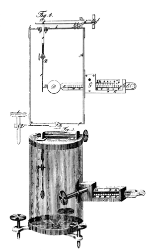
Figure 2.—“Galvanometer” was the name given by Bischof to this goldleaf electrostatic instrument in 1802, 18 years before Ampère coupled the word with the use of Oersted’s electromagnetic experiment as an indicating device.
Oersted’s Discovery
Many writers have expressed surprise that with all the use made of voltaic cells after 1800, including the enormous cells that produced the electric arc and vaporized wires, no one for 20 years happened to see a deflection of any of the inevitable nearby compass needles, which were a basic component of the scientific apparatus kept by any experimenter at this time. Yet so it happened. The surprise is still greater when one realizes that many of the contemporary natural philosophers were firmly persuaded, even in the absence of positive evidence, that there must be a connection between electricity and magnetism. Oersted himself held this latter opinion, and had been seeking electromagnetic relationships more or less deliberately for several years before he made his decisive observations.
His familiarity with the subject was such that he fully appreciated the immense importance of his discovery. This accounts for his employing a rather uncommon method of publication. Instead of submitting a letter to a scientific society or a report to the editor of a journal, he had privately printed a four-page pamphlet describing his results. This, he forwarded simultaneously to the learned societies and outstanding scientists all over Europe. Written in Latin, the paper was published in various journals in English, French, German, Italian and Danish during the next few weeks.[10]
In summary, he reported that a compass needle experienced deviations when placed near a wire connecting the terminals of a voltaic battery. He described fully how the direction and magnitude of the needle deflections varied with the relative position of the wire, and the polarity of the battery, and stated “From the preceding facts, we may likewise collect that this conflict performs circles….” Oersted’s comment that the voltaic apparatus used should “be strong enough to heat a metallic wire red hot” does not excuse the 20-year delay of the discovery.
Beginnings of Electromagnetic Instrumentation
The mere locating of a compass needle above or below a suitably oriented portion of a voltaic circuit created an electrical instrument, the moment Oersted’s “effect” became known, and it was to this basic juxtaposition that Ampère quickly gave the name of galvanometer. [11] It cannot be said that the scientists of the day agreed that this instrument detected or measured “electric current,” however. Volta himself had referred to the “current” in his original circuits, and Ampère used the word freely and confidently in his electrodynamic researches of 1820-1822, but Oersted did not use it first and many of the German physicists who followed up his work avoided it for several years. As late as 1832, Faraday could make only the rather noncommittal statement: “By current I mean anything progressive, whether it be a fluid of electricity or vibrations or generally progressive forces.” [12]
Nevertheless, whatever the words or concepts they used, experimenters agreed that Oersted’s apparatus provided a method of monitoring the “strength” of a voltaic circuit and a means of comparing, for example, one voltaic battery or circuit with another.
It was perfectly clear, from Oersted’s pamphlet, that if a compass needle was deflected clockwise when the wire of a particular voltaic circuit lay above it in the magnetic meridian, the same needle would also be deflected clockwise if the wire was turned end-for-end and placed below the compass needle, without changing the rest of the circuit. Anyone perceiving this fact might deduce, as a matter of logic, that if the wire of the circuit was first passed above the needle, in the magnetic meridian, then folded and returned in a parallel path below the needle, the deflecting effect on the needle would be repeated, and a more sensitive indicator would result, assuming that any additional wire introduced has not affected the “circuit” excessively.
Since 1821, historical accounts of the origins of electromagnetism seem to have limited their credit assignments for the conception and observation of this electromagnetic “doubling” effect (or “multiplying” effect, if the folding is repeated) to three persons. Almost without exception, however, these accounts have given no specific information as to precisely what each of these three accomplished, what physical form their respective creations took, what experiments they performed, and what functional understanding they apparently had of the situation. The usual statement is simply that a compass needle was placed in a coil of wire. [13] The main purpose of the present review is to recount some of these details.
The following are the three candidates whose names are variously associated with the “invention” of the first constructed electromagnetic instrument, or “multiplier,” or primitive galvanometer.
Johann Salomo Christoph Schweigger (1779-1857) in 1820 had already been editor for several years of the Journal für Chemie und Physik, and was professor of chemistry at the University of Halle.
Johann Christian Poggendorf (1796-1877) in 1820 had only recently entered the University of Berlin as a student following several years as an apothecary’s apprentice and a brief period as an apothecary. Four years later, he succeeded Gilbert as editor of the influential Annalen der Physik, a position he held for more than 50 years.
James Cumming (1771-1861) in 1820 was professor of chemistry at Cambridge University.
Chronology and Priority
The earliest established date in the “multiplier” record is September 16, 1820, when Schweigger read his first paper to the Natural Philosophy Society of Halle. There seems to be no reason to doubt that this report justifies the frequently used label “Schweigger’s multiplier.”
In an exuberant support of Schweigger’s position, Speter [14] with no mention of Cumming and no hint of “invention” details, shows that Poggendorf in 1821 admitted Schweigger’s priority, but suffered some lapse of memory 40 years later when writing sections of his biographical dictionary, leaving a distinct suggestion that the invention was his. Further confusion for later generations resulted from some ambiguous entries in the Allgemeine Deutsche Biographie of 1888. The name “multiplier” seems not to have originated with Schweigger himself. Speter credits it to Meineke as “working” editor of Schweigger’s Journal, but Seebeck seems to have used it much earlier. [15]
Conceding priority of conception to Schweigger (Cumming has not been a real competitor on this point) does not alter the fact that all three seem to have reached their results independently of one another, that the first work of each on this subject was published within a period of five months, that there were significant differences in their conceptions of the uses and the optimum design of their devices and that between them they provided an adequate foundation for the subsequent development of the galvanometer to become the primary electrical-measuring instrument.
In the matter of publication, Schweigger, as editor of what was popularly called Schweigger’s Journal, had an obvious advantage, and presented his experiments beginnings on page 1 of the first volume of his Journal for 1821, published January 1 of that year. [16] Oersted’s paper had appeared two volumes previously. He began by referring to Oersted’s discovery as “the most interesting to be presented in a thousand years of the history of magnetism.” He was, in fact, so impressed with the epochal nature of Oersted’s achievement that he commemorated it by giving his Journal a second title so that “volume one” of the new title could begin in the year after Oersted’s publication.
Poggendorf, as a relatively junior student, had no such easy access to publicity, but he had a staunch admirer in one of his professors, Paul Erman at the University of Berlin. Erman added a seven-page postscript on Poggendorf’s invention to his book Outline of the Physical Aspects of the Electro-chemical Magnetism Discovered by Professor Oersted, published before April 1821, [17] with an introductory paragraph:
Herr Poggendorf, who is one of the most excellent ornaments of the lecture room and laboratory of the University here, carried out a very coherent and well-conceived investigation of electro-chemical magnetism, leading step-by-step to a method of amplifying this activity-phenomenon by means of itself.
The postscript begins by referring to the “condenser [Kondensator] just brought to my attention by Herr Poggendorf” and explains that he cannot release his treatise “without preliminary announcement of this subject of the highest importance.” (It can be inferred from the text that the name “condenser” was chosen because of the device’s enhancing of magnetic measurements analogously to the enhancing of electric measurements by Volta’s electrostatic “condenser.”)
Immediately on reading the book, Schweigger published extracts, mainly of the postscript, with indignant comments on Erman’s remissness (or worse) in having failed to mention Schweigger’s prior work. [18]
However, Erman was not alone in his unawareness, if it was that, of Schweigger’s discovery.
Rival editor Gilbert of the Annalen der Physik reviewed Erman at much greater length than Schweigger, reprinting most of the postscript with evident enthusiasm, and stating in his preamble that the invention is attributed to “a young physicist studying here in Berlin, Herr Poggendorf.” [19] Only in a footnote is the reader directed to another footnote in the next article in the volume, where Gilbert finally states that he “cannot leave unmentioned the fact that this amplifying apparatus seems to be due to Herr Professor Schweigger.” He then quotes rather fully from Schweigger’s first two papers.[16] Oersted in 1823 explained the situation thus: “The work of M. Poggendorf, having been mentioned in a book on electromagnetism by the celebrated M. Erman published very shortly after its discovery, became known to many scientists before that of M. Schweigger. This is the reason for the same apparatus carrying different names.” [20]
The same confusion is well illustrated by the paper to which Gilbert attached his confessional footnote mentioned above. Written by Professor Raschig of Dresden, on April 3, 1821, the paper is entitled “Experiments with the Electro-magnetic Multiplier,” but the device, throughout the paper, is repeatedly referred to in the phrase “Poggendorf’s condenser, or rather multiplier,” an awkward combination that suggests editorial intervention. [21]
The work of James Cumming at Cambridge is described in two papers which he read to the Cambridge Philosophical Society in 1821, which were then duly published in the Transactions of that Society. The first, “On the Connexion of Galvanism and Magnetism,” was read April 2, 1821, [22] and the second, “On the Application of Magnetism as a Measure of Electricity,” was read a few weeks later on May 21st. [23]
Though he quotes some unrelated 18th-century experiments by Ritter in Germany, an 1807 publication of Oersted’s, and electromagnetic experiments with solenoids performed by Arago and Ampère in late 1820, Cumming makes no mention of Schweigger or Poggendorf, and never uses the word “multiplier.” It, therefore, seems probable that his work was done without knowledge of the German publications or inventions.
Original Electromagnetic Multipliers
Of the three sets of instruments made, respectively, by Schweigger, Poggendorf and Cumming, those of Schweigger are the most elementary, and the least realistic from a practical point of view. He makes little effort to investigate the effect of any design parameters, but presents some odd conductor configurations that involve unimportant variations of the basic principle. The following extracts from his first three papers[13] contain the major references to his conception, construction, and use of his multiplier.
PAPER READ IN HALLE, SEPTEMBER 16, 1820
That a powerful voltaic pile is required for these experiments (of Oersted) I have confirmed in my physics lectures, using an electric pile that was so strong it would easily produce potassium metal the second and third day after it was built. However, I soon saw that the electromagnetic effect was related, not to the pile, but to the simple circuit, and I was thereby led to perform the experiment with much greater sensitivity. To amplify these electromagnetic phenomena of the simple circuit it seemed to me necessary to adopt a different arrangement from that initiated by Volta, in order that the electrical phenomena of his simple circuit might be raised to a higher degree.
Since a reversal of the effect occurs according to whether the connecting-wire lies over or under the needle, and likewise according to whether the wire leads from the positive or negative pole, thence I say it is an easy inference that a doubling of the effect is attainable, which is verified in practice.
I present to the Society the simple “doubling apparatus” [Verdoppelungs-Apparat], where the compass is placed between two wires passing around it. A multiplication of the effect is easily obtained when the wire is not just once but many times wound around. A single turn suffices, however, to demonstrate Oersted’s experiments, using small strips of zinc and copper dipped in ammonium-chloride solution.
Amid innumerable, rambling theorizations (such as, that “hydrogenation affects magnetism as oxidation affects galvanism,” or “sulphur, phosphorous and carbon are especially significant in magnetism, since iron in combination with any of these inflammable materials becomes a magnet-material”), Schweigger announces that he looked for the reactive force of the needle on the connecting wire in the simple Oersted experiment, and that he used his “amplifying apparatus” to look for magnetic effects from an electrostatic machine, but without success in both cases. He suggests that he will continue with many more electromagnetic experiments because “with the use of the doubling-apparatus, the needle, instead of needing for excitation a cell capable of generating sparks, approaches more closely the sensitivity of a twitching nerve.” However, “additional special experiments are required to find to what limits the amplification can be increased by the method I have created in the construction of this doubling-apparatus, using multiple turns of wire.”
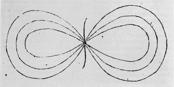
Figure 3.—This wire “bow-pattern” was the first illustration Schweigger gave of his “doubling apparatus,” though he had presented a verbal description of a single-coil arrangement somewhat earlier. The purpose of the bow pattern was to show that compass needles at the centers of the two loops deflected in opposite directions. (From Journal für Chemie und Physik.)
PAPER READ IN HALLE, NOVEMBER 4, 1820
[The first half of this paper describes successful observations of the reaction-force of a magnetic needle on the connecting wire of a voltaic circuit, achieved by pivoting the connecting wire in the form of brass needles above and below the compass needle. Though the multiplier configuration of needle and wire is in fact present here, Schweigger does not mention it, evidently regarding this as a separate project. He continues.]
In my lecture of September 16th, I showed that Oersted’s results depend, not on the voltaic cell, but only on the connecting circuit. The principle I have used for amplification of the effects, for the construction of an electromagnetic battery as it were, was the winding of wire around the compass, and I now present to the Society a bow-pattern of multiple-wound, wax-insulated wire, Figure 3. [There were no illustrations with Schweigger’s first paper.] While a single wire, using the weak electric circuit here, deflects the magnetic needle only 30° or 40°, if the compass is placed in one of the openings of this pattern, the needle is deflected 90° to the east, or in the other opening 90° to the west, using the same weak electric circuit….
The “bow-pattern” device has novelty interest only, adding nothing to the elucidation of the multiplier phenomenon. The same is true of Schweigger’s next proposal, shown in figure 4. “… I will now add another apparatus, which is just an extension of the previous one, whereby the needle can take up any angle from 0° to 180°.” A short length of circular glass tubing, of inside diameter large enough to contain a compass needle, stands with its axis vertical and has single or multiple loops of wire wound on it in vertical diametral planes. In the illustration, successive plane coils are inclined at 30° to one another. “… the electric current flows through the whole wire, and the needle moves under all of these currents, and coming always into another loop can take any desired angle.”
With much further theorizing about “the correlation of magnetism with the cohesion of bodies,” Schweigger states again his evaluation of his discovery: “Oersted succeeded in electromagnetic research by using a spark-producing cell, which could make a wire glow. My amplifying electromagnetic device needs only a weak circuit of copper, zinc, and ammonium chloride solution.” [24]
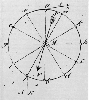
Figure 4.—Schweigger made this peculiar construction of wire coils, wound endwise on a short vertical section of glass tubing with a compass needle inside, merely to startle his Halle audience with the fact that the compass needle could rest in any of several stable positions. (From Journal für Chemie und Physik.)
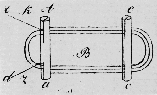
Figure 5.—Schweigger’s suggestion of one possible design for an amplifying electromagnetic indicator. The components are wooden rods and insulated wire. Position b referred to in the text is at the bottom of the diagram between the letters a and c. (From Journal für Chemie und Physik.)
“FURTHER WORDS ABOUT THE NEW MAGNETIC PHENOMENA”
[This was presumably written between November 4, 1820, and the January 1, 1821, publication date of his Journal.]
These wonderful new electrical effects [25] are most easily rendered perceptible with the help of the previously described wire loops. To focus attention on just one of the windings of Figure 3, we sketch a new drawing, Figure 5…. Since it is of major importance that these loops be made of silk-covered wire lying evenly on one another, it is convenient to wind the loops on two small slotted sticks of wood, although it is also possible to hold the wires together with wax or shellac, or to tie them together in an orderly manner with silk thread….
In Figure 5, Aa and Cc represent little slotted rods of wood on which the silk-covered wire is wound. Only three windings are shown in the figure, but I generally adopt three times that many. Now t is connected with the copper and d with the zinc, and the compass B set between the rods Aa and Cc with the coil perpendicular to the magnetic meridian and the terminals d, t at the east.
The instant Z and K are dipped in the ammonium chloride solution, the needle turns around and stays with the north pole point south….
If now the compass is taken out of the coil and put in position b, all effects are reversed, and are considerably weaker, for obvious reasons….
It is of the same significance whether we bring the compass from B to b in Figure 5, or from mesh 1 to mesh 2 in Figure 3, only that in the latter case, because the compass is enclosed by the two sides, a stronger effect results….
If now the coil is rotated … so that the face previously north now faces south, then on connecting the electric circuit there is absolutely no trace of effect on the needle, assuming that the terminal wires are not reversed….
It seems unnecessary to note that our magnetic coil can be placed in the direction of the magnetic meridian or at any arbitrary angle with it….
Following several pages of further talk about the relation of “cohesion to magnetism” and about “unipolar and bipolar conductors,” the only additional item of interest is the observation that discharges of a Leyden jar (Kleistichen Flasche) strong enough to burn strips of leaf gold and to magnetize an iron rod in a coil, produced no compass-needle deflections, even with the help of the “amplifying apparatus.”
Schweigger, therefore, described the basic multiplier idea clearly enough in his first paper, but offered no sketch of the simplest construction until the third paper. In the second paper, meanwhile, he had illustrated two peculiar designs involving the principle in less elementary ways.
His indifference to whether the wire loops lie in the magnetic meridian (fig. 3) or perpendicular to it (fig. 5) or “at any other arbitrary angle to it,” reveals a poor appreciation of the measuring-instrument potentialities. His conception seems to be primarily that of a detector.
Poggendorf’s invention, as first reported by Erman and presented to a wider audience by Gilbert [26] was described as consisting of typically 40 to 50 turns of 1/10-line diameter, silk-covered copper wire tied tightly together, with the whole pressed laterally to form an elliptical opening in which a pivoted compass needle could move freely while maintaining clearance of about 2 lines from the wire at all points. [27]
“This magnetic condenser can be a great boon to electro-chemistry,” said Erman, for “it avoids all the difficulties of electric condensers.” He noted that, using the condenser, Poggendorf had already established the electric series for a great number of bodies, discovered various anomalies about conductivities, and found a way of detecting dissymmetry of the poles of a compass needle. On the other hand, even with the condenser, no magnetic effects have so far been obtainable from a strong tourmaline, or from a 12,000-pair, Zamboni dry cell.
Poggendorf’s own account of his work finally appeared as a very long article in the journal known as “Oken’s Isis.” [28] The editorial controversies mentioned earlier may have occasioned this use of a periodical of such minor status in the fields of physics and chemistry.
The source of Poggendorf’s vision of the multiplier principle was a little different from Schweigger’s inspiration. Aiming at some detailed analysis of Oersted’s observation, Poggendorf ran the connecting wire of his cell-circuit along a vertical line to just above or below the pivot-point of the compass needle, then, after a right-angle bend, horizontally above or below one of the poles of the needle. As he studied the deflections produced for all four possible positions of such a wire, with both cell polarities, he came to realize that if a rectangular wire loop in a vertical plane enclosed a compass needle, all parts of the horizontal sides of the loop would produce additive deflections. By a separate experiment, he showed that the vertical sides of the loop would also increase the deflections. He saw at the same time that the effect of additional turns would be cumulative.