VOLUME XIV SLICE II Hydromechanics to Ichnography (continued 2)
Reading edition
π3 (2n + 1)3 ch (2n + 1) ½πb/a
(2)
an elliptic-function Fourier series; with a similar expression for ψ2 with x and y, a and b interchanged; and thence ψ = ψ1 + ψ2.
Example 4.—Parabolic cylinder, axial advance, and liquid streaming past.
The polar equation of the cross-section being
r1/2 cos ½θ = a1/2, or r + x = 2a,
(3)
the conditions are satisfied by
ψ′ = Ur sin θ − 2Ua1/2r1/2 sin ½θ = 2Ur1/2 sin ½θ (r1/2 cos ½θ − a1/2),
(4)
ψ = 2Ua1/2r1/2 sin ½θ = −U √ [ 2a (r − x) ],
(5)
w = −2Ua1/2z1/2,
(6)
and the resistance of the liquid is 2πρaV2/2g.
A relative stream line, along which ψ′ = Uc, is the quartic curve
y − c = √ [ 2a (r − x) ], x = (4a2y2 − (y − c)4 , r = 4a2y2 + (y − c)4 ,
4a (y − c)2 4a (y − c)2
(7)
and in the absolute space curve given by ψ,
dy = − (y − c)2 , x = 2ac − 2a log (y − c).
dx 2ay y − c
(8)
34. Motion symmetrical about an Axis.—When the motion of a liquid is the same for any plane passing through Ox, and lies in the plane, a function ψ can be found analogous to that employed in plane motion, such that the flux across the surface generated by the revolution of any curve AP from A to P is the same, and represented by 2π (ψ − ψ0); and, as before, if dψ is the increase in ψ due to a displacement of P to P′, then k the component of velocity normal to the surface swept out by PP′ is such that 2πdψ = 2πyk·PP′; and taking PP′ parallel to Oy and Ox,
u = −dψ/ydy, v = dψ/ydx,
(1)
and ψ is called after the inventor, “Stokes’s stream or current function,” as it is constant along a stream line (Trans. Camb. Phil. Soc., 1842; “Stokes’s Current Function,” R. A. Sampson, Phil. Trans., 1892); and dψ/yds is the component velocity across ds in a direction turned through a right angle forward.
In this symmetrical motion
ξ = 0, η = 0, 2ζ = d ( 1 dψ ) + d ( 1 dψ )
dx y dx dy y dy
= 1 ( d2ψ + d2ψ − 1 dψ ) = − 1 ∇2ψ,
y dx2 dy2 y dy y
(2)
suppose; and in steady motion,
dH + 1 dψ ∇2ψ = 0, dH + 1 dψ ∇2ψ = 0,
dx y2 dx dy y2 dy
(3)
so that
2ζ/y = −y−2∇2ψ = dH/dψ
(4)
is a function of ψ, say ƒ′(ψ), and constant along a stream line;
dH/dv = 2qζ, H − ƒ(ψ) = constant,
(5)
throughout the liquid.
When the motion is irrotational,
ζ = 0, u = − dφ = − 1 dψ , v = − dφ = 1 dψ ,
dx y dy dy y dx
(6)
∇2ψ = 0, or d2ψ + d2ψ − 1 dψ = 0.
dx2 dy2 y dy
(7)
Changing to polar coordinates, x = r cos θ, y = r sin θ, the equation (2) becomes, with cos θ = μ,
r2 d2ψ + (1 − μ2) d2ψ = 2 ζr3 sin θ,
dr2 dμ
(8)
of which a solution, when ζ = 0, is
ψ = ( Arn+1 + B ) (1 − μ2) dPn = ( Arn − 1 + B ) y2 dPn ,
rn dμ rn+2 dμ
(9)
φ = { (n + 1) Arn − nBr−n−1 } Pn,
(10)
where Pn denotes the zonal harmonic of the nth order; also, in the exceptional case of
ψ = A0 cos θ, φ = A0/r; ψ = B0r, φ = −B0 log tan ½θ = −½B0 sh−1 x/y.
(11)
Thus cos θ is the Stokes’ function of a point source at O, and PA − PB of a line source AB.
The stream function ψ of the liquid motion set up by the passage of a solid of revolution, moving with axial velocity U, is such that
1 dψ = −U dy , ψ + ½Uy2 = constant,
y ds ds
(12)
over the surface of the solid; and ψ must be replaced by ψ′ = ψ + ½Uy2 in the general equations of steady motion above to obtain the steady relative motion of the liquid past the solid.
For instance, with n = 1 in equation (9), the relative stream function is obtained for a sphere of radius a, by making it
ψ′ = ψ + ½Uy2 = ½U (r2 − a3/r) sin2 θ, ψ = −½Ua3 sin2 θ/r;
(13)
and then
φ′ = Ux (1 + ½a3/r2), φ = ½Ua3 cos θ/r2,
(14)
− dφ = U a3 cos θ, − dφ = ½U a3 sin θ,
dr r3 r dθ r3
(15)
so that, if the direction of motion makes an angle ψ with Ox,
tan (ψ − θ) = ½ tan θ, tan ψ = 3 tan θ/(2 − tan2 θ),
(16)
Along the path of a liquid particle ψ′ is constant, and putting it equal to ½Uc2,
(r2 − a3/r) sin2 θ = c2, sin2 θ = c2r / (r3 − a3),
(17)
the polar equation; or
y2 = c2r3 / (r3 − a3), r3 = a3y2 / (y2 − c2),
(18)
a curve of the 10th degree (C10).
In the absolute path in space
cos ψ = (2 − 3 sin2 θ) / √ (4 − sin2 θ), and sin3 θ = (y3 − c2y) / a3,
(19)
which leads to no simple relation.
The velocity past the surface of the sphere is
1 dψ′ = ½U ( 2r + a3 ) sin2 θ = 3⁄2 U sin θ, when r = a;
r sin θ dr r2 r sin θ
(20)
so that the loss of head is
(9⁄4 sin2 θ − 1) U2/2g, having a maximum 5⁄4 U2/2g,
(21)
which must be less than the head at infinite distance to avoid cavitation at the surface of the sphere.
With n = 2, a state of motion is given by
ψ = −½ Uy2a4 μ/r4, ψ′ = ½ Uy2 (1 − a4 μ/r4),
(22)
φ′ = Ux + φ, φ = −1⁄3 U (a4 / r3) P2, P2 = 3⁄2 μ2 − ½,
(23)
representing a stream past the surface r4 = a4μ.
35. A circular vortex, such as a smoke ring, will set up motion symmetrical about an axis, and provide an illustration; a half vortex ring can be generated in water by drawing a semicircular blade a short distance forward, the tip of a spoon for instance. The vortex advances with a certain velocity; and if an equal circular vortex is generated coaxially with the first, the mutual influence can be observed. The first vortex dilates and moves slower, while the second contracts and shoots through the first; after which the motion is reversed periodically, as if in a game of leap-frog. Projected perpendicularly against a plane boundary, the motion is determined by an equal opposite vortex ring, the optical image; the vortex ring spreads out and moves more slowly as it approaches the wall; at the same time the molecular rotation, inversely as the cross-section of the vortex, is seen to increase. The analytical treatment of such vortex rings is the same as for the electro-magnetic effect of a current circulating in each ring.
36. Irrotational Motion in General.—Liquid originally at rest in a singly-connected space cannot be set in motion by a field of force due to a single-valued potential function; any motion set up in the liquid must be due to a movement of the boundary, and the motion will be irrotational; for any small spherical element of the liquid may be considered a smooth solid sphere for a moment, and the normal pressure of the surrounding liquid cannot impart to it any rotation.
The kinetic energy of the liquid inside a surface S due to the velocity function φ is given by
T = ½ρ ∫ ∫ ∫ [ ( dφ ) 2 + ( dφ ) 2 + ( dφ ) 2 ] dx dy dz,
dx dy dz
= ½ρ ∫ ∫ φ dφ dS
dν
(1)
by Green’s transformation, dν denoting an elementary step along the normal to the exterior of the surface; so that dφ/dν = 0 over the surface makes T = 0, and then
( dφ ) 2 + ( dφ ) 2 + ( dφ ) 2 = 0, dφ = 0, dφ = 0, dφ = 0.
dx dy dz dx dy dz
(2)
If the actual motion at any instant is supposed to be generated instantaneously from rest by the application of pressure impulse over the surface, or suddenly reduced to rest again, then, since no natural forces can act impulsively throughout the liquid, the pressure impulse ῶ satisfies the equations
1 dῶ = −u, 1 dῶ = −v, 1 dῶ = ῶ,
ρ dx ρ dy ρ dz
(3)
ῶ = ρφ + a constant,
(4)
and the constant may be ignored; and Green’s transformation of the energy T amounts to the theorem that the work done by an impulse is the product of the impulse and average velocity, or half the velocity from rest.
In a multiply connected space, like a ring, with a multiply valued velocity function φ, the liquid can circulate in the circuits independently of any motion of the surface; thus, for example,
φ = mθ = m tan−1 y/x
(5)
will give motion to the liquid, circulating in any ring-shaped figure of revolution round Oz.
To find the kinetic energy of such motion in a multiply connected space, the channels must be supposed barred, and the space made acyclic by a membrane, moving with the velocity of the liquid; and then if k denotes the cyclic constant of φ in any circuit, or the value by which φ has increased in completing the circuit, the values of φ on the two sides of the membrane are taken as differing by k, so that the integral over the membrane
∫ ∫ φ dφ dS = k ∫ ∫ dφ dS,
dν dν
(6)
and this term is to be added to the terms in (1) to obtain the additional part in the kinetic energy; the continuity shows that the integral is independent of the shape of the barrier membrane, and its position. Thus, in (5), the cyclic constant k = 2πm.
In plane motion the kinetic energy per unit length parallel to Oz
T = ½ρ ∫ ∫ [ ( dφ ) 2 + ( dφ ) 2 ] dx dy = ½ρ ∫ ∫ [ ( dψ ) 2 + ( dψ ) 2 ] dx dy
dx dy dx dy
= ½ρ ∫ φ dφ ds = ½ρ ∫ ψ dψ ds.
dν dν
(7)
For example, in the equilateral triangle of (8) § 28, referred to coordinate axes made by the base and height,
ψ′ = −2Rαβγ/h = −½ Ry [ (h − y)2 − 3x2 ] /h
(8)
ψ = ψ′ − ½R [ ( 1⁄3 h − y)2 + x2 ] = −½R [ ½h3 + 1⁄3 h2y + h) (x2 − y2) − 3x2y + y3 ] /h
(9)
and over the base y = 0,
dx/dν = −dx/dy = + ½R ( 1⁄3 h2 − 3x2) / h, ψ = −½R ( 1⁄9 h2 + x2).
(10)
Integrating over the base, to obtain one-third of the kinetic energy T,
1⁄3T = ½ρ ∫ h / √3 ¼R2 (3x4 − 1⁄27 h4) dx/h = ρR2 h4 / 135 √3
−h / √3
(11)
so that the effective k2 of the liquid filling the triangle is given by
k2 = T / ½ρR2A = 2h2 / 45 = 2⁄5 (radius of the inscribed circle)2,
(12)
or two-fifths of the k2 for the solid triangle.
Again, since
dφ/dν = dψ/ds, dφ/ds = −dψ/dν,
(13)
T = ½ρ ∫ φ dψ = −½ρ ∫ ψ dφ.
(14)
With the Stokes’ function ψ for motion symmetrical about an axis.
T = ½ρ ∫ φ dψ 2πy ds = πρ ∫ φ dψ.
y ds
(15)
37. Flow, Circulation, and Vortex Motion.—The line integral of the tangential velocity along a curve from one point to another, defined by
∫ ( u dx + v dy + w dz ) ds = ∫ (u dx + v dy + z dz),
ds ds ds
(1)
is called the “flux” along the curve from the first to the second point; and if the curve closes in on itself the line integral round the curve is called the “circulation” in the curve.
With a velocity function φ, the flow
−∫ dφ = φ1 − φ2,
(2)
so that the flow is independent of the curve for all curves mutually reconcilable; and the circulation round a closed curve is zero, if the curve can be reduced to a point without leaving a region for which φ is single valued.
If through every point of a small closed curve the vortex lines are drawn, a tube is obtained, and the fluid contained is called a vortex filament.
By analogy with the spin of a rigid body, the component spin of the fluid in any plane at a point is defined as the circulation round a small area in the plane enclosing the point, divided by twice the area. For in a rigid body, rotating about Oz with angular velocity ζ, the circulation round a curve in the plane xy is
∫ ζ ( x dy − y dx ) ds = ζ times twice the area.
ds ds
(3)
In a fluid, the circulation round an elementary area dxdy is equal to
u dx + ( v + dv dx ) dy − ( u + du dy ) dx − vdy = ( dv − du ) dx dy,
dx dy dx dy
(4)
so that the component spin is
½ ( dv − du ) = ζ,
dx dy
(5)
in the previous notation of § 24; so also for the other two components ξ and η.
Since the circulation round any triangular area of given aspect is the sum of the circulation round the projections of the area on the coordinate planes, the composition of the components of spin, ξ, η, ζ, is according to the vector law. Hence in any infinitesimal part of the fluid the circulation is zero round every small plane curve passing through the vortex line; and consequently the circulation round any curve drawn on the surface of a vortex filament is zero.
If at any two points of a vortex line the cross-section ABC, A′B′C′ is drawn of the vortex filament, joined by the vortex line AA′, then, since the flow in AA′ is taken in opposite directions in the complete circuit ABC AA′B′C′ A′A, the resultant flow in AA′ cancels, and the circulation in ABC, A′B′C′ is the same; this is expressed by saying that at all points of a vortex filament ωα is constant where α is the cross-section of the filament and ω the resultant spin (W. K. Clifford, Kinematic, book iii.).
So far these theorems on vortex motion are kinematical; but introducing the equations of motion of § 22,
Du + dQ = 0, Dv + dQ = 0, Dw + dQ = 0,
dt dx dt dy dt dz
(6)
Q = ∫ dp/ρ + V,
(7)
and taking dx, dy, dz in the direction of u, v, w, and
dx : dy : dz = u : v : w,
D ( u dx + v dy + w dz ) = Du dx + u D dx + ... = −dQ + ½ dq2,
dt dt dt
(8)
and integrating round a closed curve
D ∫ (u dx + v dy + w dz) = 0,
dt
(9)
and the circulation in any circuit composed of the same fluid particles is constant; and if the motion is differential irrotational and due to a velocity function, the circulation is zero round all reconcilable paths. Interpreted dynamically the normal pressure of the surrounding fluid on a tube cannot create any circulation in the tube.
The circulation being always zero round a small plane curve passing through the axis of spin in vortical motion, it follows conversely that a vortex filament is composed always of the same fluid particles; and since the circulation round a cross-section of a vortex filament is constant, not changing with the time, it follows from the previous kinematical theorem that αω is constant for all time, and the same for every cross-section of the vortex filament.
A vortex filament must close on itself, or end on a bounding surface, as seen when the tip of a spoon is drawn through the surface of water.
Denoting the cross-section α of a filament by dS and its mass by dm, the quantity ωdS/dm is called the vorticity; this is the same at all points of a filament, and it does not change during the motion; and the vorticity is given by ω cosεdS/dm, if dS is the oblique section of which the normal makes an angle ε with the filament, while the aggregate vorticity of a mass M inside a surface S is
M−1 ∫ ω cos ε dS.
Employing the equation of continuity when the liquid is homogeneous,
2 ( dζ − dη ) = ∇2u, ... , ∇2 = − d2 − d2 − d2 ,
dy dz dx2 dy2 dz2
(10)
which is expressed by
∇2 (u, v, w) = 2 curl (ξ, η, ζ), (ξ, η, ζ) = ½ curl (u, v, w).
(11)
38. Moving Axes in Hydrodynamics.—In many problems, such as the motion of a solid in liquid, it is convenient to take coordinate axes fixed to the solid and moving with it as the movable trihedron frame of reference. The components of velocity of the moving origin are denoted by U, V, W, and the components of angular velocity of the frame of reference by P, Q, R; and then if u, v, w denote the components of fluid velocity in space, and u′, v′, w′ the components relative to the axes at a point (x, y, z) fixed to the frame of reference, we have
u = U + u′ − yR + zQ, v = V + v′- zP + xR, w = W + w′ − xQ + yP.
(1)
Now if k denotes the component of absolute velocity in a direction fixed in space whose direction cosines are l, m, n,
k = lu + mv + nw;
(2)
and in the infinitesimal element of time dt, the coordinates of the fluid particle at (x, y, z) will have changed by (u′, v′, w′)dt; so that
Dk = dl u + dm v + dn w
dt dt dt dt
+ l ( du + u′ du + v′ du + w′ du )
dt dx dy dz
+ m ( dv + u′ dv + v′ dv + w′ dv )
dt dx dy dz
+ n ( dw + u′ dw + v′ dw + w′ dw ).
dt dx dy dz
(3)
But as l, m, n are the direction cosines of a line fixed in space,
dl = mR − nQ, dm = nP − lR, dn = lQ − mP;
dt dt dt
(4)
so that
Dk = l ( du − vR + wQ + u′ du + v′ du + w′ du ) + m (...) + n (...)
dt dt dx dy dz
= l ( X − 1 dp ) + m ( Y − 1 dp ) + n ( Z − 1 dp ),
p dx p dy p dz
(5)
for all values of l, m, n, leading to the equations of motion with moving axes.
When the motion is such that
u = − dφ − m dψ , v = − dφ − m dψ , w = − dφ − m dψ ,
dx dx dy dy dz dz
(6)
as in § 25 (1), a first integral of the equations in (5) may be written
∫ dp + V + ½q2 − dφ − m dψ + (u − u′) ( dφ + m dψ )
ρ dt dt dx dx
+ (v − v′) ( dφ + m dψ ) + (w − w′) ( dφ + m dψ ) = F(t),
dy dy dz dz
(7)
in which
dφ − (u − u′) dφ − (v − v′) dφ − (w − w′) dφ
dt dx dy dz
= dφ − (U − yR + zQ) dφ − (V − zP + xR) dφ − (W − xQ + yP) dφ
dt dx dy dz
(8)
is the time-rate of change of φ at a point fixed in space, which is left behind with velocity components u − u′, v − v′, w − w′.
In the case of a steady motion of homogeneous liquid symmetrical about Ox, where O is advancing with velocity U, the equation (5) of § 34
p/ρ + V + ½q′2 − ƒ (ψ′) = constant
(9)
becomes transformed into
p + V + ½q2 − U dψ + ½U2 − ƒ (ψ + ½Uy2) = constant,
ρ y dy
(10)
ψ′ = ψ + ¼U y2,
(11)
subject to the condition, from (4) § 34,
y−2 ∇2ψ′ = −ƒ′(ψ′), y−2 ∇2ψ = −ƒ′ (ψ + ½Uy2).
(12)
Thus, for example, with
ψ′ = ¾U y2 (r2a−2 − 1), r2 = x2 + y2,
(13)
for the space inside the sphere r = a, compared with the value of ψ′ in § 34 (13) for the space outside, there is no discontinuity of the velocity in crossing the surface.
Inside the sphere
2ζ = d ( 1 dψ′ ) + d ( 1 dψ′ ) = 15 U y ,
dx y dx dy y dy 2 a2
(14)
so that § 34 (4) is satisfied, with
ƒ′ (ψ′) = 15 Ua−2, ƒ (ψ′) = 15 Uψ′ a−2;
2 2
(15)
and (10) reduces to
p + V − 9 U { ( x2 − 1 ) 2 − ( y2 − ½ ) 2 } = constant;
ρ 8 a2 a2
(16)
this gives the state of motion in M. J. M. Hill’s spherical vortex, advancing through the surrounding liquid with uniform velocity.
39. As an application of moving axes, consider the motion of liquid filling the ellipsoidal case
x2 + y2 + z2 = 1;
a2 b2 c2
(1)
and first suppose the liquid to be frozen, and the ellipsoid to be rotating about the centre with components of angular velocity ξ, η, ζ; then
u = − yζ + zη, v = − zξ + xζ, w = − xη + yξ.
(2)
Now suppose the liquid to be melted, and additional components of angular velocity Ω1, Ω2, Ω3 communicated to the ellipsoidal case; the additional velocity communicated to the liquid will be due to a velocity-function
φ = − Ω1 b2 − c2 yz − Ω2 c2 − a2 zx − Ω3 a2 − b2 xy,
b2 + c2 c2 + a2 a2 + b2
(3)
as may be verified by considering one term at a time.
If u′, v′, w′ denote the components of the velocity of the liquid relative to the axes,
u′ = u + yR − zQ = 2a2 Ω3y − 2a2 Ω2z,
a2 + b2 c2 + a2
(4)
v′ = v + zP − xR = 2b2 Ω1z − 2b2 Ω3x,
b2 + c2 a2 + b2
(5)
w′ = w + xQ − yP = 2c2 Ω2x − 2c2 Ω1y,
c2 + a2 b2 + c2
(6)
P = Ω1 + ξ, Q = Ω2 + η, R = Ω3 + ζ.
(7)
Thus
u′ x + v′ y + w′ z = 0,
a2 b2 c2
(8)
so that a liquid particle remains always on a similar ellipsoid.
The hydrodynamical equations with moving axes, taking into account the mutual gravitation of the liquid, become
1 dp + 4πρAx + du − vR + wQ + u′ du + v′ du + w′ du = 0, ... , ... ,
ρ dx dt dx dy dz
(9)
where
A, B, C = ∫∞0 abcdλ
(a2 + λ, b2 + λ, c2 + λ) P
P2 = 4 (a2 + λ) (b2 + λ) (c2 + λ).
(10)
With the values above of u, v, w, u′, v′, w′, the equations become of the form
1 dp + 4πρ Ax + αx + hy + gz = 0,
ρ dx
(11)
1 dp + 4πρBy + hx + βy + fz = 0,
ρ dy
(12)
1 dp + 4πρCz + gx + fy + γz = 0,
ρ dz
(13)
and integrating
pρ−1 + 2πρ (Ax2 + By2 + Cz2) + ½ (αx2 + βy2 + γz2 + 2fyz + 2gzx + 2hxy) = const.,
(14)
so that the surfaces of equal pressure are similar quadric surfaces, which, symmetry and dynamical considerations show, must be coaxial surfaces; and f, g, h vanish, as follows also by algebraical reduction; and
α = 4c2(c2 − a2) Ω22 − ( c2 − a2 Ω2 − η ) 2
(c2 + a2)2 c2 + a2
− 4b2(a2 − b2) Ω32 − ( a2 − b2 Ω3 − ζ ) 2 ,
(a2 + b2)2 a2 + b2
(15)
with similar equations for β and γ.
If we can make
(4πρA + α) x2 = (4πρB + β) b2 = (4πρC + γ) c2,
(16)
the surfaces of equal pressure are similar to the external case, which can then be removed without affecting the motion, provided α, β, γ remain constant.
This is so when the axis of revolution is a principal axis, say Oz; when
Ω1 = 0, Ω2 = 0, ξ = 0, η = 0.
(17)
If Ω3 = 0 or θ3 = ζ in addition, we obtain the solution of Jacobi’s ellipsoid of liquid of three unequal axes, rotating bodily about the least axis; and putting a = b, Maclaurin’s solution is obtained of the rotating spheroid.
In the general motion again of the liquid filling a case, when a = b, Ω3 may be replaced by zero, and the equations, hydrodynamical and dynamical, reduce to
dξ = − 2c2 Ω2 ζ, dη = 2a2 Ω1 ζ, dζ = 2c2 (Ω2 ξ − Ω2 η)
dt a2 + c2 dt a2 + c2 dt a2 + c2
(18)
dΩ1 = Ω2 ζ + a2 + c2 ηζ, dΩ2 = −Ω1 ζ − a2 + c2 ξζ;
dt a2 − c2 dt a2 − c2
(19)
of which three integrals are
ξ2 + η2 = L − a2 ζ2,
c2
(20)
Ω12 + Ω22 = M + (a2 + c2)2 ζ2,
2c2 (a2 − c2)
(21)
Ω1 ξ + Ω2 ηN = + a2 + c2 ζ2;
4c2
(22)
and then
( dζ ) 2 = 4c4 (Ω2ξ − Ω12η)2
dt (a2 + c2)
= 4c4 [ (ξ2 + η2) (Ω12 + Ω22) − (Ω1ξ + Ω2η)2 ]
(a2 + c2)2
= 4c4 [ LM − N2 + { (a2 + c2)2 − M a2 − N a2 + c2 } ζ2
(a2 + c2)2 2c2 (a2 + c2) c2 2c2
− (a2 + c2) (9a2 − c2) ζ4 ] = Z,
16c4 (a2 − c2)
(23)
where Z is a quadratic in ζ2, so that ζ is an elliptic function of t, except when c = a, or 3a.
Put Ω1 = Ω cos φ, Ω2 = −Ω sin φ,
Ω2 dφ = dΩ1 Ω2 − Ω1 dΩ2 = Ω2ζ − (a2 + c2) (Ω1ξ + Ω2η) ζ,
dt dt dt (a2 − c2)
(24)
dφ = ζ − (a2 + c2) · N + a2 + c2 4c2 ,
dt (a2 − c2) M + (a2 + c2)2 ζ2 2c2 (a2 − c2)
(25)
φ = ∫ ζ dζ − a2 + c2 ∫ N + a2 + c2 4c2 · ζ dζ ,
√Z a2 − c2 M + (a2 + c2)2 ζ2 2c2 (a2 − c2) √Z
(26)
which, as Z is a quadratic function of ζ2, are non-elliptic integrals; so also for ψ, where ξ = ω cos ψ, η = −ω sin ψ.
In a state of steady motion
dζ = 0, Ω1 = Ω2 ,
dt ξ η
(27)
φ = ψ = nt, suppose,
(28)
Ω1ξ + Ω2η = Ωω,
(29)
dφ = ζ − a2 + c2 ω ζ,
dt a2 − c2 Ω
(30)
dψ = − 2a2 Ω ζ,
dt a2 + c2 ω
(31)
1 − a2 + c2 ω = − 2a2 Ω ,
a2 − c2 Ω a2 + c2 ω
(32)
( ω − ½ a2 + c2 ) 2 = (a2 − c2) (9a2 − c2) ,
Ω a2 − c2 4 (a2 + c2)
(33)
and a state of steady motion is impossible when 3a > c > a.
An experiment was devised by Lord Kelvin for demonstrating this, in which the difference of steadiness was shown of a copper shell filled with liquid and spun gyroscopically, according as the shell was slightly oblate or prolate. According to the theory above the stability is regained when the length is more than three diameters, so that a modern projectile with a cavity more than three diameters long should fly steadily when filled with water; while the old-fashioned type, not so elongated, would be highly unsteady; and for the same reason the gas bags of a dirigible balloon should be over rather than under three diameters long.
40. A Liquid Jet.—By the use of the complex variable and its conjugate functions, an attempt can be made to give a mathematical interpretation of problems such as the efflux of water in a jet or of smoke from a chimney, the discharge through a weir, the flow of water through the piers of a bridge, or past the side of a ship, the wind blowing on a sail or aeroplane, or against a wall, or impinging jets of gas or water; cases where a surface of discontinuity is observable, more or less distinct, which separates the running stream from the dead water or air.
Uniplanar motion alone is so far amenable to analysis; the velocity function φ and stream function ψ are given as conjugate functions of the coordinates x, y by
w = ƒ(z) where z = x + yi, w = φ + ψi,
(1)
and then
dw = dφ + i dψ = −u + vi;
dz dx dx
(2)
so that, with u = q cos θ, v = q sin θ, the function
ζ = −Q dz = Q = Q (u + vi) = Q (cos θ + i sin θ),
dw (u − vi) q2 q
(3)
gives ζ as a vector representing the reciprocal of the velocity q in direction and magnitude, in terms of some standard velocity Q.
To determine the motion of a jet which issues from a vessel with plane walls, the vector ζ must be Constructed so as to have a constant direction θ along a plane boundary, and to give a constant skin velocity over the surface of a jet, where the pressure is constant.
It is convenient to introduce the function
Ω = log ζ = log (Q/q) + θi
(4)
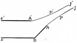
Fig. 4.
so that the polygon representing Ω conformally has a boundary given by straight lines parallel to the coordinate axes; and then to determine Ω and w as functions of a variable u (not to be confused with the velocity component of q), such that in the conformal representation the boundary of the Ω and w polygon is made to coincide with the real axis of u.
It will be sufficient to give a few illustrations.
Consider the motion where the liquid is coming from an infinite distance between two parallel walls at a distance xx′ (fig. 4), and issues in a jet between two edges A and A′; the wall xA being bent at a corner B, with the external angle β = ½π/n.
The theory of conformal representation shows that the motion is given by
ζ = [ √ (b − a′·u − a) + √(b − a·u − a′) ] 1/n , u = ae−πw/m;
√ (a − a′·u − b)
(5)
where u = a, a′ at the edge A, A′; u = b at a corner B; u = 0 across xx′ where φ = ∞; and u = ∞, φ = ∞ across the end JJ′ of the jet, bounded by the curved lines APJ, A′P′J′, over which the skin velocity is Q. The stream lines xBAJ, xA′J′ are given by ψ = 0, m; so that if c denotes the ultimate breadth JJ′ of the jet, where the velocity may be supposed uniform and equal to the skin velocity Q,
m = Qc, c = m/Q.
If there are more B corners than one, either on xA or x′A′, the expression for ζ is the product of corresponding factors, such as in (5).
Restricting the attention to a single corner B,
ζn = ( Q ) n (cos nθ + i sin nθ) = √ (b − a′·u − a) + √ (b − a·u − a′) ,
q √ (a − a′·u − b)
(6)
ch nω = ch log ( Q ) n cos nθ + i sh log ( Q ) n sin nθ
q q
= ½(ζn + ζ−n) = √ b − a′ √ u − a ,
a − a′ u − b
(7)
sh nΩ = sh log ( Q ) cos nθ + i ch log ( Q ) n sin nθ
q q
= ½(ζn + ζ−n) = √ b − a √ u − a′ ,
a − a′ u − b
(8)
∞ > a > b > 0 > a′ > −∞
(9)
and then
dΩ = − 1 √ (b − a′·b − a′) , dw = − m ,
du 2n (u − b) √ (a − a·u − a′) du πu
(10)
the formulas by which the conformal representation is obtained.
For the Ω polygon has a right angle at u = a, a′, and a zero angle at u = b, where θ changes from 0 to ½π/n and Ω increases by ½iπ/n; so that
dΩ = A , where A = √ (b − a·b − a′) .
du (u − b) √ (u − a·u − a′) 2n
(11)
And the w polygon has a zero angle at u = 0, ∞, where ψ changes from 0 to m and back again, so that w changes by im, and
dw = B , where B = − m .
du u π
(12)
Along the stream line xBAPJ,
ψ = 0, u = ae−πφ/m;
(13)
and over the jet surface JPA, where the skin velocity is Q,
dφ = −q = −Q, u = aeπsQ/m = aeπs/c,
ds
(14)
denoting the arc AP by s, starting at u = a;
ch nΩ = cos nθ = √ b − a′ √ u − a ,
a − a′ u − b
(15)
sh nΩ = i sin nθ = i √ a − b √ u − a′ ,
a − a′ u − b
(16)
∞ > u = aeπs/c > a,
(17)
and this gives the intrinsic equation of the jet, and then the radius of curvature
ρ = − ds = 1 dφ = i dw = i dw / dΩ
dθ Q dθ Q dΩ Q du du
= c · u − b √ (u − a·u − a′) ,
π u √ (a − b·b − a′)
(18)
not requiring the integration of (11) and (12)
If θ = α across the end JJ′ of the jet, where u = ∞, q = Q,
ch nΩ = cos nα = √ b − a′ , sh nΩ = i sin nα= i √ a − b ,
a − a′ a − a′
(19)
Then
cos 2nα − cos 2nθ = 2 a − b·b − a′ = ½sin2 2nα a − a′
a − a′·u − b u − b
sin 2nθ = 2 √ (a − b.b − a′) √ (u − a·u − b′)
a − a′·u − b
(20)
= sin 2nα √ (a − a·b − a′) ;
u − b
2n c ( 1 + b ) √ (a − b·b − a′)
φ ρ u − b √ (u − a·u − a′)
(21)
= a − a′ + (a + a′) cos 2nα − [ a + a′ + (a − a′) cos 2nα ] cos 2nθ × cos 2nα − cos 2nθ .
(a − a′) sin2 2nα sin 2nθ
Along the wall AB, cos nθ = 0, sin nθ = 1,
a > u > b,
(22)
ch nΩ = i sh log ( Q ) n = i √ b − a′ √ a − u ,
q a − a′ u − b
(23)
sh nΩ = i ch log ( Q ) n = i √ a − b √ u − a′ ,
q a − a′ u − b
(24)
ds = ds dφ = m = c Q
du dφ dt πqu π qu
(25)
π AB = ∫ab Q du ∫ [ √ (a − b) √ (u − a′) + √ (b − a′) √ (a − u) ] 1/n du .
c q u √ (a − a′) √ (u − b′) u
(26)
Along the wall Bx, cos nθ = 1, sin nθ = 0,
b > u > 0
(27)
ch nΩ = ch log ( Q ) n = √ b − a′ √ a − u ,
q a − a′ b − u
(28)
sh nΩ = sh log ( Q ) n = √ a − b √ u − a′ .
q a − a′ b − u
(29)
At x where φ = ∞, u = 0, and q = q0,
( Q ) n = √ b − a′ √ a + √ a − b √ −a′ .
q0 a − a′ b a − a′ q
(30)
In crossing to the line of flow x′A′P′J′, ψ changes from 0 to m, so that with q = Q across JJ′, while across xx′ the velocity is q0, so that
m = q0·xx′ = Q·JJ′
(31)
JJ′ = q0 [ √ b − a′ √ a − √ a − b √ −a′ ] 1/n ,
xx′ Q a − a′ b a − a′ b
(32)
giving the contraction of the jet compared with the initial breadth of the stream.
Along the line of flow x′A′P′J′, ψ = m, u = a′e−πφ/m, and from x′ to A′, cos nθ = 1, sin nθ = 0,
ch nΩ = ch log ( Q ) n = √ b − a′ √ a − u ,
q a − a′ b − u
(33)
sh nΩ = sh log ( Q ) n = √ a − b √ u − a′ .
q a − a′ b − u
(34)
0 > u > a′.
(35)
Along the jet surface A′J′, q = Q,
ch nΩ = cos nθ = √ b − a′ √ a − u ,
a − a′ b − u
(36)
sh nΩ = i sin nθ = i √ a − b √ u − a′ .
a − a′ b − u
(37)
a′ > u = a′eπ/sc > −∞,
(38)
giving the intrinsic equation.
41. The first problem of this kind, worked out by H. v. Helmholtz, of the efflux of a jet between two edges A and A1 in an infinite wall, is obtained by the symmetrical duplication of the above, with n = 1, b = 0, a′ = −∞, as in fig. 5,
ch Ω = √ u − a , sh Ω = √ − a ;
u u
(1)
and along the jet APJ, ∞ > u = aeπs/c > a,
sh Ω = i sin θ − i √ a = ie−1/2 πs/c,
u
(2)
PM = ∫∞s sinθ ds = ∫ e−½πs/c ds = c e−1/2 πs/c = c sin θ,
½π ½π
(3)
so that PT = c/½π, and the curve AP is the tractrix; and the coefficient of contraction, or
breadth of the jet = π .
breadth of the orifice π + 2
(4)
A change of Ω and θ into nΩ and nθ will give the solution for two walls converging symmetrically to the orifice AA1 at an angle π/n. With n = ½, the reentrant walls are given of Borda’s mouthpiece, and the coefficient of contraction becomes ½. Generally, by making a′ = −∞, the line x′A′ may be taken as a straight stream line of infinite length, forming an axis of symmetry; and then by duplication the result can be obtained, with assigned n, a, and b, of the efflux from a symmetrical converging mouthpiece, or of the flow of water through the arches of a bridge, with wedge-shaped piers to divide the stream.
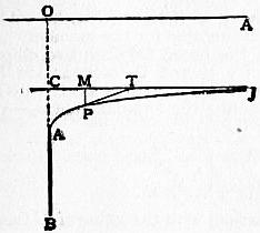
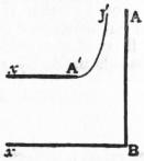
Fig. 5. Fig. 6.
42. Other arrangements of the constants n, a, b, a′ will give the results of special problems considered by J. M. Michell, Phil. Trans. 1890.
Thus with a′ = 0, a stream is split symmetrically by a wedge of angle π/n as in Bobyleff’s problem; and, by making a = ∞, the wedge extends to infinity; then
ch nΩ = √ b , sh nΩ = √ n .
b − u b − u
(1)
Over the jet surface ψ = m, q = Q,
u = − eπφ/m = − beπ2/c,
ch Ω = cos nθ = √ 1 , sh Ω = i sin nθ = i √ eπ2/c ,
eπ2/c + 1 eπ2/c + 1
(2)
e½π2/c = tan nθ, ½π ds = 2n .
c dθ sin 2nθ
(3)
For a jet impinging normally on an infinite plane, as in fig. 6, n = 1,
e½π2/c = tan θ, ch (½πs/c) sin 2θ = 1,
(4)
sh ½πx/c = cot θ, sh ½πy/c = tan θ,
sh ½πx/c sh ½πy/c = 1, e½π(x + y)/c = e1/2 πx/c + e1/2 πy/c + 1.
(5)
With n = ½, the jet is reversed in direction, and the profile is the catenary of equal strength.
In Bobyleff’s problem of the wedge of finite breadth,
ch nΩ = √ b √ u − a , sh nΩ = √ b − a √ u ,
a u − b a u − b
(6)
cos nα = √ b , sin nα = √ a − b ,
a a
(7)
and along the free surface APJ, q = Q, ψ = 0, u = e−πφ/m = aeπs/c,
cos nθ = cos nα √ eπ2/c − 1 ,
eπ2/c − cos2 nα
eπ2/c = cos2 nα sin2 nθ ,
sin2 nθ − sin2 nα
(8)
the intrinsic equation, the other free surface A′P′J′ being given by
eπ2/c = cos2 nα sin2 nθ ,
sin2 nα − sin2 nθ
(9)
Putting n = 1 gives the case of a stream of finite breadth disturbed by a transverse plane, a particular case of Fig. 7.
When a = b, α = 0, and the stream is very broad compared with the wedge or lamina; so, putting w = w′(a − b)/a in the penultimate case, and
u = ae−w ≈ a − (a − b)w′,
(10)
ch nΩ = √ w′ + 1 , sh nΩ = √ 1 ,
w′ √ w′
(11)
in which we may write
w′ = φ + ψi.
(12)
Along the stream line xABPJ, ψ = 0; and along the jet surface APJ, −1 > φ > −∞; and putting φ = −πs/c − 1, the intrinsic equation is
πs/c = cot2 nθ,
(13)
which for n = 1 is the evolute of a catenary.
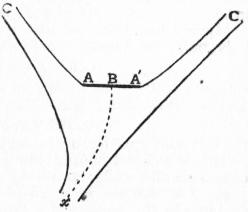
Fig. 7.
43. When the barrier AA′ is held oblique to the current, the stream line xB is curved to the branch point B on AA′ (fig. 7), and so must be excluded from the boundary of u; the conformal representation is made now with
dΩ = − √ (b − a·b − a′)
du (u − b) √ (u − a·u − a′)
(1)
dw = − m 1 − m′ 1 ,
du π u − j π u − j
= − m + m′ · u − b ,
π u − j·u − j′
b = mj′ + m′j ,
m + m′
(2)
taking u = ∞ at the source where φ = ∞, u = b at the branch point B, u = j, j′ at the end of the two diverging streams where φ = −∞; while ψ = 0 along the stream line which divides at B and passes through A, A′; and ψ = m, −m′ along the outside boundaries, so that m/Q, m′/Q is the final breadth of the jets, and (m + m′)/Q is the initial breadth, c1 of the impinging stream. Then
ch ½Ω = √ b − a′ √ u − b , sh ½Ω = √ b − a √ u − a′ ,
a − a′ u − b a − a′ u − b
(3)
ch Ω = 2b − a − a′ − N ,
a − a′ u − b
sh Ω = √ N √ (2·a − u·u − a′) ,
u − b
N = 2 a − b·b − a′ .
a − a′
(4)
Along a jet surface, q = Q, and
chΩ = cos θ = cos α − ½sin2 α(a − a′) / (u − b),
(5)
if θ = α at the source x of the jet xB, where u = ∞; and supposing θ = β, β′ at the end of the streams where u = j, j′,
u − b = ½sin2 α , u − j ½sin2 α cosθ − cosβ ,
a − a′ cos α − cos θ a − a′ (cos α − cos β) (cos α − cos θ)
u − j′ = ½sin2 α cos θ − cos β′ ;
a − a′ (cosα − cos β′) (cos α − cosθ)
(6)
and ψ being constant along a stream line
dφ = dw , Q ds = dφ = dw du ,
du du dθ dθ du dθ
πQ ds = π ds = (cos α − cos β) (cos α − cos β′) sin θ ,
m + m′ dθ c dθ (cos α − cos θ) (cos θ − cos β) (cos θ − cos α′)
= sin θ + cos α − cos β′ · sin θ
cos α − cos θ cos β − cos β′ cos θ − cos β
cos α − cos β · sin θ ,
cos β − cos β′ cos θ − cos β′
(7)
giving the intrinsic, equation of the surface of a jet, with proper attention to the sign.
From A to B, a > u > b, θ = 0,
ch Ω = ch log Q = cos α − ½ sin2 α a − a′
q a − b
sh Ω = sh log Q = √ (a − u·u − a′) sinα
q u − b
Q = (u − b) cos α − ½ (a − a′) sin2 α + √ (a − u·u − a′) sin α
q u − b
(8)
Q ds = Q ds dφ = − Q dw
du dφ du q du
= m + m′ · (u − b) cos α − ½ (a − a′) sin2 α + √ (a − u·u − a′) sin α
π j − u·u − j′
π AB = ∫ab (2b − a − a′) (u − b) − 2(a − b) (b − a′) + 2√ (a − b·b − a′·a − u·u − a′) du,
c a − a′·j − u·u − j′
(10)
with a similar expression for BA′.
The motion of a jet impinging on an infinite barrier is obtained by putting j = a, j′ = a′; duplicated on the other side of the barrier, the motion reversed will represent the direct collision of two jets of unequal breadth and equal velocity. When the barrier is small compared with the jet, α = β = β′, and G. Kirchhoff’s solution is obtained of a barrier placed obliquely in an infinite stream.
Two corners B1 and B2 in the wall xA, with a′ = −∞, and n = 1, will give the solution, by duplication, of a jet issuing by a reentrant mouthpiece placed symmetrically in the end wall of the channel; or else of the channel blocked partially by a diaphragm across the middle, with edges turned back symmetrically, problems discussed by J. H. Michell, A. E. H. Love and M. Réthy.
When the polygon is closed by the walls joining, instead of reaching back to infinity at xx′, the liquid motion must be due to a source, and this modification has been worked out by B. Hopkinson in the Proc. Lond. Math. Soc., 1898.
Michell has discussed also the hollow vortex stationary inside a polygon (Phil. Trans., 1890); the solution is given by
ch nΩ = sn w, sh nΩ = i cn w
(11)
so that, round the boundary of the polygon, ψ = K′, sin nθ = 0; and on the surface of the vortex ψ = 0, q = Q, and
cos nθ = sn φ, nθ = ½π − am s/c,
(12)
the intrinsic equation of the curve.
This is a closed Sumner line for n = 1, when the boundary consists of two parallel walls; and n = ½ gives an Elastica.
44. The Motion of a Solid through a Liquid.—An important problem in the motion of a liquid is the determination of the state of velocity set up by the passage of a solid through it; and thence of the pressure and reaction of the liquid on the surface of the solid, by which its motion is influenced when it is free.
Beginning with a single body in liquid extending to infinity, and denoting by U, V, W, P, Q, R the components of linear and angular velocity with respect to axes fixed in the body, the velocity function takes the form
φ = Uφ1 + Vφ2 + Wφ3 + Pχ1 + Qχ2 + Rχ3,
(1)
where the φ’s and χ’s are functions of x, y, z, depending on the shape of the body; interpreted dynamically, C − ρφ represents the impulsive pressure required to stop the motion, or C + ρφ to start it again from rest.
The terms of φ may be determined one at a time, and this problem is purely kinematical; thus to determine φ1, the component U alone is taken to exist, and then l, m, n, denoting the direction cosines of the normal of the surface drawn into the exterior liquid, the function φ1 must be determined to satisfy the conditions
(i.) ∇2φ1 = 0. throughout the liquid;
(ii.) dφ1/dυ = −l, the gradient of φ down the normal at the surface of the moving solid;
(iii.) dφ1/dυ = 0, over a fixed boundary, or at infinity;
similarly for φ2 and φ3.
To determine χ1 the angular velocity P alone is introduced, and the conditions to be satisfied are
(i.) ∇2χ1 = 0, throughout the liquid;
(ii.) dχ1/dυ = mz − ny, at the surface of the moving body, but zero over a fixed surface, and at infinity; the same for χ2 and χ3.
For a cavity filled with liquid in the interior of the body, since the liquid inside moves bodily for a motion of translation only,
φ1 = −x, φ2 = −y, φ3 = −z;
(2)
but a rotation will stir up the liquid in the cavity, so that the χ’s depend on the shape of the surface.
The ellipsoid was the shape first worked out, by George Green, in his Research on the Vibration of a Pendulum in a Fluid Medium (1833); the extension to any other surface will form an important step in this subject.
A system of confocal ellipsoids is taken
x2 + y2 + z2 = 1
a2 + λ b2 + λ c2 + λ
(3)
and a velocity function of the form
φ = xψ,
(4)
where ψ is a function of λ only, so that ψ is constant over an ellipsoid; and we seek to determine the motion set up, and the form of ψ which will satisfy the equation of continuity.
Over the ellipsoid, p denoting the length of the perpendicular from the centre on a tangent plane,
l = px , m = py , n = pz
a2 + λ b2 + λ c2 + λ
(5)
1 = p2x2 + p2y2 + p2z2 ,
(a2 + λ)2 (b2 + λ)2 (c2 + λ)2
p2 = (a2 + λ) l2 + (b2 + λ) m2 + (c2 + λ) n2, = a2l2 + b2m2 + c2n2 + λ,
(7)
2p dp = dλ ;
ds ds
(8)
Thence
dφ = dx ψ + x dψ
ds ds ds
= dx ψ + 2 (a2 + λ) dψ l dp ,
ds dλ ds
(9)
so that the velocity of the liquid may be resolved into a component -ψ parallel to Ox, and −2(a2 + λ)l dψ/dλ along the normal of the ellipsoid; and the liquid flows over an ellipsoid along a line of slope with respect to Ox, treated as the vertical.
Along the normal itself
dφ { ψ + 2(a2 + λ) dψ } l,
ds dλ
(10)
so that over the surface of an ellipsoid where λ and ψ are constant, the normal velocity is the same as that of the ellipsoid itself, moving as a solid with velocity parallel to Ox
U = −ψ − 2 (a2 + λ) dψ ,
dλ
(11)
and so the boundary condition is satisfied; moreover, any ellipsoidal surface λ may be supposed moving as if rigid with the velocity in (11), without disturbing the liquid motion for the moment.
The continuity is secured if the liquid between two ellipsoids λ and λ1, moving with the velocity U and U1 of equation (11), is squeezed out or sucked in across the plane x = 0 at a rate equal to the integral flow of the velocity ψ across the annular area α1 − α of the two ellipsoids made by x = 0; or if
αU − α1U1 = ∫λ1λ ψ dα dλ,
dλ
(12)
α = π√ (b2 + λ.c2 + λ).
(13)
Expressed as a differential relation, with the value of U from (11),
d [ αψ + 2 (a2 + λ) α dψ ] − ψ dα = 0,
dλ dλ dλ
(14)
3α dψ + 2 (a2 + λ) d ( α dψ ) = 0,
dλ dλ dλ
(15)
and integrating
(a2 + λ)3/2 α dψ = a constant,
dλ
(16)
so that we may put
ψ = ∫ M dλ ,
(a2 + λ) P
(17)
P2 = 4 (a2 + λ) (b2 + λ) (c2 + λ),
(18)
where M denotes a constant; so that ψ is an elliptic integral of the second kind.
The quiescent ellipsoidal surface, over which the motion is entirely tangential, is the one for which
2 (a2 + λ) dψ + ψ = 0,
dλ
(19)
and this is the infinite boundary ellipsoid if we make the upper limit λ1 = ∞.
The velocity of the ellipsoid defined by λ = 0 is then
U = −2a2 dψ0 − ψ0
dλ
= M − ∫∞0 M dλ
abc (a2 + λ)P
= M (1 − A0),
abc
(20)
with the notation
A or Aλ = ∫∞λ abc dλ
(a2 + λ) P
= −2abc d ∫∞λ dλ ,
da2 P
(21)
so that in (4)
φ = M xA = UxA , φ1 = xAλ ,
abc 1 − A0 1 − A0
(22)
in (1) for an ellipsoid.
The impulse required to set up the motion in liquid of density ρ is the resultant of an impulsive pressure ρφ over the surface S of the ellipsoid, and is therefore
∫ ∫ ρφl dS = ρψ0 ∫ ∫ xl dS = ρψ0 (volume of the ellipsoid) = ψ0W′,
(23)
where W′ denotes the weight of liquid displaced.
Denoting the effective inertia of the liquid parallel to Ox by αW′. the momentum
αW′U = ψ0W′
(24)
α = ψ0 = A0 ;
U 1 − A0
(25)
in this way the air drag was calculated by Green for an ellipsoidal pendulum.
Similarly, the inertia parallel to Oy and Oz is
βW′ = B0 W′, γW′ = C0 W′,
1 − B0 1 − C0
(26)
Bλ, Cλ = ∫∞λ abc dλ ;
(b2 + λ, c2 + λ) P
(27)
and
A + B + C = abc / ½P, A0 + B0 + C0 = 1.
(28)
For a sphere
a = b = c, A0 = B0 = C0 = 1⁄3, α = β = γ = ½,
(29)
so that the effective inertia of a sphere is increased by half the weight of liquid displaced; and in frictionless air or liquid the sphere, of weight W, will describe a parabola with vertical acceleration
W − W′ g.
W + ½W′
(30)
Thus a spherical air bubble, in which W/W′ is insensible, will begin to rise in water with acceleration 2g.
45. When the liquid is bounded externally by the fixed ellipsoid λ = λ1, a slight extension will give the velocity function φ of the liquid in the interspace as the ellipsoid λ = 0 is passing with velocity U through the confocal position; φ must now take the form x(ψ + N), and will satisfy the conditions in the shape
φ = Ux A + B1 + C1 = Ux abc + ∫λ1λ abcdλ a1b1c1 (a2 + λ) P ,
B0 + C0 − B1 − C1 1 − abc − ∫λ10 abcdλ a1b1c1 (a2 + λ) P
(1)
and any confocal ellipsoid defined by λ, internal or external to λ = λ1, may be supposed to swim with the liquid for an instant, without distortion or rotation, with velocity along Ox
U Bλ + Cλ − B1 − C1 .
B0 + C0 − B1 − C1
Since − Ux is the velocity function for the liquid W′ filling the ellipsoid λ = 0, and moving bodily with it, the effective inertia of the liquid in the interspace is
A0 + B1 + C1 W′.
B0 + C0 − B1 − C1
(2)
If the ellipsoid is of revolution, with b = c,
φ = ½Ux A + 2B1 ,
B0 − B1
(3)
and the Stokes’ current function ψ can be written down
ψ = − ½ Uy2 B − B1 ;
B0 − B1
(4)
reducing, when the liquid extends to infinity and B1 = 0, to
φ = ½ Ux A , ψ = − ½ Uy2 B ;
B0 B0
(5)
so that in the relative motion past the body, as when fixed in the current U parallel to xO,
φ′ = ½Ux ( 1 + A ), ψ′ = ½Uy2 ( 1 − B ).
B0 B0
(6)
Changing the origin from the centre to the focus of a prolate spheroid, then putting b2 = pa, λ = λ′a, and proceeding to the limit where a = ∞, we find for a paraboloid of revolution
B = ½ p , B = p ,
p + λ′ B0 p + λ′
(7)
y2 = p + λ′ − 2x,
p + λ′
(8)
with λ′ = 0 over the surface of the paraboloid; and then
ψ′ = ½ U [ y2 − p √ (x2 + y2) + px ];
(9)
ψ = −½ Up [ √ (x2 + y2) − x ];
(10)
φ = −½ Up log [ √ (x2 + y2) + x ].
(11)
The relative path of a liquid particle is along a stream line
ψ′ = ½ Uc2, a constant,
(12)
x = p2y2 − (y2 − c2)2 , √ (x2 + y2) = p2y2 − (y2 − c2)2
2p (y2 − c2) 2p (y2 − c2)
(13)
a C4; while the absolute path of a particle in space will be given by
dy = − r − x = y2 − c2 ,
dx y 2py
(14)
y2 − c2 = a2 e−x/p.
(15)
46. Between two concentric spheres, with
a2 + λ = r2, a2 + λ1 = a12,
(1)
A = B = C = a3 / 3r3,
φ = ½ Ux a3/r3 + 2 a3/a13 , ψ = ½ Uy2 a3/r3 − a3/a13 ;
1 − a4/a12 1 − a3/a13
(2)
and the effective inertia of the liquid in the interspace is
A0 + 2A1 W′ = ½ a13 + 2a3 W′.
2A0 − 2A1 a13 − a3
(3)
When the spheres are not concentric, an expression for the effective inertia can be found by the method of images (W. M. Hicks, Phil. Trans., 1880).
The image of a source of strength μ at S outside a sphere of radius a is a source of strength μa/ƒ at H, where OS = ƒ, OH = a2/ƒ, and a line sink reaching from the image H to the centre O of line strength −μ/a; this combination will be found to produce no flow across the surface of the sphere.
Taking Ox along OS, the Stokes’ function at P for the source S is μ cos PSx, and of the source H and line sink OH is μ(a/ƒ) cos PHx and −(μ/a)(PO − PH); so that
ψ = μ ( cos PSx + a cos PHx − PO − PH ),
ƒ a
(4)
and ψ = −μ, a constant, over the surface of the sphere, so that there is no flow across.
When the source S is inside the sphere and H outside, the line sink must extend from H to infinity in the image system; to realize physically the condition of zero flow across the sphere, an equal sink must be introduced at some other internal point S′.
When S and S′ lie on the same radius, taken along Ox, the Stokes’ function can be written down; and when S and S′ coalesce a doublet is produced, with a doublet image at H.
For a doublet at S, of moment m, the Stokes’ function is
m d cos PSx = −m y2 ;
dƒ PS3
(5)
and for its image at H the Stokes’ function is
m d cos PHx = −m a3 y2 ;
dƒ ƒ3 PH3
(6)
so that for the combination
ψ = my2 ( a3 1 − 1 ) = m y2 ( a3 − ƒ3 ),
ƒ3 PH3 PS3 ƒ3 PH3 PS3
(7)
and this vanishes over the surface of the sphere.
There is ao Stokes’ function when the axis of the doublet at S does not pass through O; the image system will consist of an inclined doublet at H, making an equal angle with OS as the doublet S, and of a parallel negative line doublet, extending from H to O, of moment varying as the distance from O.
A distribution of sources and doublets over a moving surface will enable an expression to be obtained for the velocity function of a body moving in the presence of a fixed sphere, or inside it.
The method of electrical images will enable the stream function ψ′ to be inferred from a distribution of doublets, finite in number when the surface is composed of two spheres intersecting at an angle π/m, where m is an integer (R. A. Herman, Quart. Jour. of Math. xxii.).
Thus for m = 2, the spheres are orthogonal, and it can be verified that
ψ′ = ½ Uy2 ( 1 − a13 − a23 + a3 ),
r13 r23 r3
(8)
where a1, a2, a = a1a2/√ (a12 + a22) is the radius of the spheres and their circle of intersection, and r1, r2, r the distances of a point from their centres.
The corresponding expression for two orthogonal cylinders will be
ψ′ = Uy ( 1 − a12 − a22 + a2 ).
r12 r22 r2
(8)
With a2 = ∞, these reduce to
ψ′ = ½Uy2 ( 1 − a5 ) x , or Uy ( 1 − a4 ) x ,
r5 a r4 a
(10)
for a sphere or cylinder, and a diametral plane.
Two equal spheres, intersecting at 120°, will require
ψ′ = ½Uy2 [ x − a3 + a4 (a − 2x) + a3 − a4 (a + 2x) ],
a 2r13 2r15 2r23 2r25
(11)
with a similar expression for cylinders; so that the plane x = 0 may be introduced as a boundary, cutting the surface at 60°. The motion of these cylinders across the line of centres is the equivalent of a line doublet along each axis.
47. The extension of Green’s solution to a rotation of the ellipsoid was made by A. Clebsch, by taking a velocity function
φ = xyχ
(1)
for a rotation R about Oz; and a similar procedure shows that an ellipsoidal surface λ may be in rotation about Oz without disturbing the motion if
R = − [ 1/ (a2 + λ) + 1/ (b2 + λ) ] χ + 2 dx/dλ ,
1 / (b2 + λ) − 1 / (a2 + λ)
(2)
and that the continuity of the liquid is secured if
(a2 + λ)3/2 (b2 + λ)3/2 (c2 + λ) ½ dχ = constant,
dλ
(3)
χ = ∫∞λ N dλ = N · Bλ − Aλ ;
(a2 + λ) (b2 + λ) P abc a2 − b2
(4)
and at the surface λ = 0,
R = − [ (1/a2 + 1/b2) · N/abc · (B0 − A0)/(a2 − b2) ] − N/abc · 1/a2b2 ,
1/b2 − 1/a2
(5)
N = R 1/b2 − 1/a2 ,
abc 1/a2b2 − [ (1/a2 + 1/b2) · (B0 − A0) / (a2 − b2) ]
(6)
= R (a2 − b2)2 / (a2 + b2)
(a2 − b2) / (a2 + b2) − (B0 − A0)
The velocity function of the liquid inside the ellipsoid λ = 0 due to the same angular velocity will be
φ1 = Rxy (a2 − b2) / (a2 + b2),
(7)
and on the surface outside
φ0 = xyχ0 = xy N B0 − A0 ,
abc a2 − b2
(8)
so that the ratio of the exterior and interior value of φ at the surface is
φ0 = B0 − A0 ,
φ1 (a2 − b2) / (a2 + b2) − (B0 − A0)
(9)
and this is the ratio of the effective angular inertia of the liquid, outside and inside the ellipsoid λ = 0.
The extension to the case where the liquid is bounded externally by a fixed ellipsoid λ = λ1 is made in a similar manner, by putting
φ = xy (χ + M),
(10)
and the ratio of the effective angular inertia in (9) is changed to
(B0 − A0) − (B1 − A1) + a12 − b12 abc a12 + b12 a1b1c1 .
a2 − b2 − a12 − b12 abc − (B0 − A0) + (B1 − A1) a2 + b2 a12 + b12 a1b1c1
(11)
Make c = ∞ for confocal elliptic cylinders; and then
Aλ = ∫∞λ ab = ab ( 1 − √ b2 + λ ),
(a2 + λ) √ (4a2 + λb2 + λ) a2 − b2 a2 + λ
(12)
Bλ = ab ( √ a2 + λ − 1 ), Cλ = 0;
a2 − b2 b2 + λ
and then as above in § 31, with
a = c ch α, b = c sh α, a1 = √ (a2 + λ) = c ch α1, b1 = c sh α1
(13)
the ratio in (11) agrees with § 31 (6).
As before in § 31, the rotation may be resolved into a shear-pair, in planes perpendicular to Ox and Oy.
A torsion of the ellipsoidal surface will give rise to a velocity function of the form φ = xyzΩ, where Ω can be expressed by the elliptic integrals Aλ, Bλ, Cλ, in a similar manner, since
Ω = L ∫∞λ dλ / P3.
48. The determination of the φ’s and χ’s is a kinematical problem, solved as yet only for a few cases, such as those discussed above.
But supposing them determined for the motion of a body through a liquid, the kinetic energy T of the system, liquid and body, is expressible as a quadratic function of the components U, V, W, P, Q, R. The partial differential coefficient of T with respect to a component of velocity, linear or angular, will be the component of momentum, linear or angular, which corresponds.
Conversely, if the kinetic energy T is expressed as a quadratic function of x1, x2, x3, y1, y2, y3, the components of momentum, the partial differential coefficient with respect to a momentum component will give the component of velocity to correspond.
These theorems, which hold for the motion of a single rigid body, are true generally for a flexible system, such as considered here for a liquid, with one or more rigid bodies swimming in it; and they express the statement that the work done by an impulse is the product of the impulse and the arithmetic mean of the initial and final velocity; so that the kinetic energy is the work done by the impulse in starting the motion from rest.
Thus if T is expressed as a quadratic function of U, V, W, P, Q, R, the components of momentum corresponding are
x1 = dT , x2 = dT , x3 = dT ,
dU dV dW
(1)
y1 = dT , y2 = dT , y3 = dT ;
dP dQ dR
but when it is expressed as a quadratic function of x1, x2, x3, y1, y2, y3,
U = dT , V = dT , W = dT ,
dx1 dx2 dx3
(2)
P = dT , Q = dT , R = dT .
dy1 dy2 dy3
The second system of expression was chosen by Clebsch and adopted by Halphen in his Fonctions elliptiques; and thence the dynamical equations follow
X = dx1 − x2 dT + x3 dT , Y = ..., Z = ...,
dt dy3 dy2
(3)
L = dy1 − y2 dT + y3 dT − x2 dT + x3 dT , M = ..., N = ...,
dt dy3 dy2 dx3 dx2
(4)
where X, Y, Z, L, M, N denote components of external applied force on the body.
These equations are proved by taking a line fixed in space, whose direction cosines are l, m, n, then
dl = mR − nQ, dm = nP − lR, dn = lQ − mP.
dt dt dt
(5)
If P denotes the resultant linear impulse or momentum in this direction
P = lx1 + mx2 + nx3,
(6)
dP = dl x1 + dm x2 + dn x3
dt dt dt dt
+ l dx1 + m dx2 + n dx3 ,
dt dt dt
= l ( dx1 − x2R + x3Q )
dt
+ m ( dx2 − x3P + x1R )
dt
+ n ( dx3 − x1Q + x2P )
dt
= lX + mY + nZ,
(7)
for all values of l, m, n.
Next, taking a fixed origin Ω and axes parallel to Ox, Oy, Oz through O, and denoting by x, y, z the coordinates of O, and by G the component angular momentum about Ω in the direction (l, m, n)
G = l (y1 − x2z + x3y) + m (y2 − x3x + x1z) + n (y3 − x1y + x2x).
(8)
Differentiating with respect to t, and afterwards moving the fixed origin up to the moving origin O, so that
x = y = z = 0, but dx = U, dy = V, dz = W,
dt dt dt
dG = l ( dy1 − y2R + y3Q − x2W + x3V )
dt dt
+ m ( dy2 − y3P + y1R − x3U + x1W )
dt
+ n ( dy3 − y1Q + y2P − x1V + x2U )
dt
= lL + mM + nN,
(9)
for all values of l, m, n.
When no external force acts, the case which we shall consider, there are three integrals of the equations of motion
(i.) T = constant,
(ii.) x12 + x22+ x32 = F2, a constant,
(iii.) x1y1 + x2y2 + x3y3 = n = GF, a constant;
and the dynamical equations in (3) express the fact that x1, x2, x3 are the components of a constant vector having a fixed direction; while (4) shows that the vector resultant of y1, y2, y3 moves as if subject to a couple of components
x2W − x3V, x3U − x1W, x1V − x2U,
(10)
and the resultant couple is therefore perpendicular to F, the resultant of x1, x2, x3, so that the component along OF is constant, as expressed by (iii).
If a fourth integral is obtainable, the solution is reducible to a quadrature, but this is not possible except in a limited series of cases, investigated by H. Weber, F. Kötter, R. Liouville, Caspary, Jukovsky, Liapounoff, Kolosoff and others, chiefly Russian mathematicians; and the general solution requires the double-theta hyperelliptic function.
49. In the motion which can be solved by the elliptic function, the most general expression of the kinetic energy was shown by A. Clebsch to take the form
T = ½p (x12 + x22) + ½p′x32 + q (x1y1 + x2y2) + q′x3y3 + ½r (y12 + y22) + ½r′y32
(1)
so that a fourth integral is given by
dy3 / dt = 0, y3 = constant;
(2)
dx3 = x1 (qx2 + ry2) − x2 (qx1 + ry1) = r (x1y2 − x2y1),
dt
(3)
1 ( dx3 ) 2 = (x12 + x22) (y12 + y22) − (x1y1 + x2y2)2
r2 dt
= (x12 + x22) (y12 + y22) − (FG − x3y3)2 = (x12 + x22) (y12 + y22 + y32 − G2) − (Gx3 − Fy3)2,
(4)
in which
x12 + x22 = F2 − x32, x1y1 + x2y2 = FG − x3y3,
(5)
r (y12 + y22) = 2T − p(x12 + x22) − p′x32 − 2q (x1y1 + x2y2) − 2q′x3y3 − r′y32 = (p − p′) x32 + 2 (q − q′) x3y3 + m1,
(6)
m1 − 2T − pF2 − 2qFG − r1y32
(7)
so that
1 ( dx3 ) 2 = X3
r2 dt
(8)
where X3 is a quartic function of x3, and thus t is given by an elliptic integral of the first kind; and by inversion x3 is in elliptic function of the time t. Now
(x1 − x2i) (y1 + y2i) = x1y1 + x2y2 + i (x1y2 − x2y1) = FG − xy3y3 + i √ X3,
(9)
y1 + y2i = FG − x3y3 + i √ X3 ,
x1 + x2i x12 + x22
(10)
d (x1 + x2i) = −i [ (q′ − q) x3 + r′y3 ] + irx3 (y1 + y2i),
dt
(11)
d log (x1 + x2i) = −(q′ − q) x3 − r′y3 + rx3 FG − x3y3 + i √ X3 ,
dti F2 − x32
(12)
d log √ x1 + x2i = −(q′ − q) x3 − (r′ − r) y3 − Fr Fy3 − Gx3 ,
dti x1 − x2i F2 − x32
(13)
requiring the elliptic integral of the third kind; thence the expression of x1 + x2i and y1 + y2i.
Introducing Euler’s angles θ, φ, ψ,
x1 = F sin θ sin φ, x2 = F sin θ cos φ, x1 + x2i = iF sin θε−ψi, x3 = F cos θ;
(14)
sin θ dψ = P sin φ + Q cos φ,
dt
(15)
F sin2 θ dψ = dT x1 + dT x2
dt dy1 dy2
= (qx1 + ry1) x1 + (qx2 + ry2) x2 = q (x12 + x22) + r (x1y1 + x2y2) = gF2 sin2 θ + r (FG − x3y3),
(16)
ψ − qFt = ∫ FG − x3y3 Fr dx3 ,
F2 − x32 √ X3
(17)
elliptic integrals of the third kind.
Employing G. Kirchhoff’s expressions for X, Y, Z, the coordinates of the centre of the body,
FX = y1 cos xY + y2 cos yY + y3 cos zY,
(18)
FY = −y1 cos xX + y2 cos yX + y3 cos zX,
(19)
G = y1 cos xZ + y2 cos yZ + y3 cos zZ,
(20)
F2(X2 + Y2) = y12 + y22 + y32 − G2,
(21)
F(X + Yi) = Fy3 − Gx3 + i √ X3 εψi.
√ (F2 − x32)
(22)
Suppose x3 − F is a repeated factor of X3, then y3 = G, and
X3 = (x3 − F)2 [ p′ − p (x3 + F)2 + 2 q′ − q G (x3 + F) − G2 ],
r r
(23)
and putting x3 − F = y,
( dy ) 2 = r2y2 [ 4 p′ − p F2 + 4 q′ − q FG − G2 + 2 ( 2 p′ − p F + q′ − q G ) y + p′ − p y2 ],
dt r r r r r
(24)
so that the stability of this axial movement is secured if
A = 4 p′ − p F2 + 4 q′ − q FG − G2
r r
(25)
is negative, and then the axis makes r√(-A)/π nutations per second. Otherwise, if A is positive
rt = ∫ dy
y √ (A + 2By + Cy2)
= 1 sh−1 √ A √ (A + 2By + Cy2) = 1 ch−1 A + By ,
√ A ch−1 y√ (B2 ~ AC) √A sh−1 y √ (B2 ~ AC)
(26)
and the axis falls away ultimately from its original direction.
A number of cases are worked out in the American Journal of Mathematics (1907), in which the motion is made algebraical by the use of the pseudo-elliptic integral. To give a simple instance, changing to the stereographic projection by putting tan ½θ = x,
(Nx eψi)3/2 = (x + 1) √ X1 + i (x − 1) √ X2,
(27)
X1 = ± ax4 + 2ax3 ± 3 (a + b) x2 + 2bx ± b,
X2
(28)
N3 = −8 (a + b),
(29)
will give a possible state of motion of the axis of the body; and the motion of the centre may then be inferred from (22).
50. The theory preceding is of practical application in the investigation of the stability of the axial motion of a submarine boat, of the elongated gas bag of an airship, or of a spinning rifled projectile. In the steady motion under no force of such a body in a medium, the centre of gravity describes a helix, while the axis describes a cone round the direction of motion of the centre of gravity, and the couple causing precession is due to the displacement of the medium.
In the absence of a medium the inertia of the body to translation is the same in all directions, and is measured by the weight W, and under no force the C.G. proceeds in a straight line, and the axis of rotation through the C.G. preserves its original direction, if a principal axis of the body; otherwise the axis describes a cone, right circular if the body has uniaxial symmetry, and a Poinsot cone in the general case.
But the presence of the medium makes the effective inertia depend on the direction of motion with respect to the external shape of the body, and on W′ the weight of fluid medium displaced.
Consider, for example, a submarine boat under water; the inertia is different for axial and broadside motion, and may be represented by
c1 = W + W′α, c2 = W + W′β,
(1)
where α, β are numerical factors depending on the external shape; and if the C.G. is moving with velocity V at an angle φ with the axis, so that the axial and broadside component of velocity is u = V cos φ, v = V sin φ, the total momentum F of the medium, represented by the vector OF at an angle θ with the axis, will have components, expressed in sec. ℔,
F cos θ = c1 u = (W + W′α) V cos φ, F sin θ = c2 v = (W + W′β) V .
g g g g
(2)
Suppose the body is kept from turning as it advances; after t seconds the C.G. will have moved from O to O′, where OO′ = Vt; and at O′ the momentum is the same in magnitude as before, but its vector is displaced from OF to O′F′.
For the body alone the resultant of the components of momentum
W V cos φ and W V sin φ is W V sec. ℔,
g g g
(3)
acting along OO′, and so is unaltered.
But the change of the resultant momentum F of the medium as well as of the body from the vector OF to O′F′ requires an impulse couple, tending to increase the angle FOO′, of magnitude, in sec. foot-pounds
F·OO′·sin FOO′ = FVt sin (θ − φ),
(4)
equivalent to an incessant couple
N = FV sin (θ − φ) = (F sin θ cos φ − F cos θ sin φ) V = (c2 − c1) (V2 / g) sin φ cos φ = W′ (β − α) uv / g.
(5)
This N is the couple in foot-pounds changing the momentum of the medium, the momentum of the body alone remaining the same; the medium reacts on the body with the same couple N in the opposite direction, tending when c2 − c1 is positive to set the body broadside to the advance.
An oblate flattened body, like a disk or plate, has c2 − c1 negative, so that the medium steers the body axially; this may be verified by a plate dropped in water, and a leaf or disk or rocket-stick or piece of paper falling in air. A card will show the influence of the couple N if projected with a spin in its plane, when it will be found to change its aspect in the air.
An elongated body like a ship has c2 − c1 positive, and the couple N tends to disturb the axial movement and makes it unstable, so that a steamer requires to be steered by constant attention at the helm.
Consider a submarine boat or airship moving freely with the direction of the resultant momentum horizontal, and the axis at a slight inclination θ. With no reserve of buoyancy W = W′, and the couple N, tending to increase θ, has the effect of diminishing the metacentric height by h ft. vertical, where
Wh tan θ = N = (c2 − c1) c1 u2 tan θ,
c2 g
(6)
h = c2 − c1 c1 u2 = (β − α) 1 + α u2 .
W c2 g 1 + β g
(7)
51. An elongated shot is made to preserve its axial flight through the air by giving it the spin sufficient for stability, without which it would turn broadside to its advance; a top in the same way is made to stand upright on the point in the position of equilibrium, unstable statically but dynamically stable if the spin is sufficient; and the investigation proceeds in the same way for the two problems (see Gyroscope).
The effective angular inertia of the body in the medium is now required; denote it by C1 about the axis of the figure, and by C2 about a diameter of the mean section. A rotation about the axis of a figure of revolution does not set the medium in motion, so that C1 is the moment of inertia of the body about the axis, denoted by Wk12. But if Wk22 is the moment of inertia of the body about a mean diameter, and ω the angular velocity about it generated by an impulse couple M, and M′ is the couple required to set the surrounding medium in motion, supposed of effective radius of gyration k′,
Wk22ω = M − M′, W′k′2ω = M′,
(1)
(Wk22 + W′k′2) ω = M,
(2)
C2 = Wk22 + W′k′2 = (W + W′ε) k22,
(3)
in which we have put k′2 = εk2, where ε is a numerical factor depending on the shape.
If the shot is spinning about its axis with angular velocity p, and is preceding steadily at a rate μ about a line parallel to the resultant momentum F at an angle θ, the velocity of the vector of angular momentum, as in the case of a top, is
C1pμ sinθ − C2μ2 sin θ cos θ;
(4)
and equating this to the impressed couple (multiplied by g), that is, to
gN = (c1 − c2) c1 u2 tan θ,
c2
(5)
and dividing out sin θ, which equated to zero would imply perfect centring, we obtain
C2μ2 cos θ − C1pμ + (c2 − c1) c1 u2 sec θ = 0.
c2
(6)
The least admissible value of p is that which makes the roots equal of this quadratic in μ, and then
μ = ½ C1 p sec θ,
C2
(7)
the roots would be imaginary for a value of p smaller than given by
C12p2 − 4 (c2 − c1) c1 C2u2 = 0,
c2
(8)
p2 = 4 (c2 − c1) c1 C2 .
u2 c2 C12
(9)
Table of Rifling for Stability of an Elongated Projectile, x Calibres long, giving δ the Angle of Rifling, and n the Pitch of Rifling in Calibres.
Cast-iron Common Shell ƒ = 2⁄3, S.G. 7.2. Palliser Shell ƒ = ½, S.G. 8. Solid Steel Bullet ƒ = 0, S.G. 8. Solid Lead Bullet ƒ = 0, S.G. 10.9.
x β − α δ n δ n δ n δ n
1.0 0.0000 0° 0′ Infinity 0° 0′ Infinity 0° 0′ Infinity 0° 0′ Infinity
2.0 0.4942 2 49 63.87 2 32 71.08 2 29 72.21 2 08 84.29
2.5 0.6056 3 46 47.91 3 23 53.32 3 19 54.17 2 51 63.24
3.0 0.6819 4 41 38.45 4 13 42.79 4 09 43.47 3 38 50.74
3.5 0.7370 5 35 32.13 5 02 35.75 4 58 36.33 4 15 42.40
4.0 0.7782 6 30 27.60 5 51 30.72 5 45 31.21 4 56 36.43
4.5 0.8100 7 24 24.20 6 40 26.93 6 32 27.36 5 37 31.94
5.0 0.8351 8 16 21.56 7 28 23.98 7 21 24.36 6 18 28.44
6.0 0.8721 10 05 17.67 9 04 19.67 8 56 19.98 7 40 23.33
10.0 0.9395 16 57 10.31 15 19 11.47 15 05 11.65 13 00 13.60
Infinity 1.0000 90 00 0.00 90 00 0.00 90 00 0.00 90 00 0.00
If the shot is moving as if fired from a gun of calibre d inches, in which the rifling makes one turn in a pitch of n calibres or nd inches, so that the angle δ of the rifling is given by
tan δ = πd / nd = ½ dp / u,
(10)
which is the ratio of the linear velocity of rotation ½dp to u, the velocity of advance,
tan2 δ = π2 = d2p2 = (c2 − c1) c1 C2d2
n2 4u2 c2 C12
= W′ (β − α) 1 + W′ α W · ( 1 + W′ ε ) ( k1 ) 2 W d .
W 1 + W′ β W ( k1 ) 4 W
(11)
For a shot in air the ratio W′/W is so small that the square may be neglected, and formula (11) can be replaced for practical purpose in artillery by
tan2 δ = π2 = W′ (β − α) ( k2 ) 2 / ( k1 ) 4 ,
n2 W d d
(12)
if then we can calculate β, α, or β − α for the external shape of the shot, this equation will give the value of δ and n required for stability of flight in the air.
The ellipsoid is the only shape for which α and β have so far been determined analytically, as shown already in § 44, so we must restrict our calculation to an egg-shaped bullet, bounded by a prolate ellipsoid of revolution, in which, with b = c,
A0 = ∫∞0 ab2 dλ = ∫∞0 ab2 dλ ,
(a2 + λ) √ [ 4 (a2 + λ) (b2 + λ)2 ] 2 (a2 + λ)3/2 (b2 + λ)
(13)
A0 + 2B0 = 1,
(14)
a = A0 , β = B0 = 1 − A0 = 1 .
1 − A0 1 − B0 1 + A0 1 + 2α
(15)
The length of the shot being denoted by l and the calibre by d, and the length in calibres by x
l / d = 2a / 2b = x,
(16)
A0 = x ch−1x − 1 ,
(x2− 1)3/2 x2 − 1
(17)
2B0 = − x ch−1x + x2 ,
(x2 − 1)3/2 x2 + 1
(18)
x2A0 + 2B0 = x sh−1 √ (x2 − 1) = x log [ x + √ (x2 − 1) ].
√ (x2 − 1) √ (x2 − 1)
(19)
If σ denotes the density of the metal, and if the shell has a cavity homothetic with the external ellipsoidal shape, a fraction f of the linear scale; then the volume of a round shot being 1⁄6 π d3, and 1⁄6 π d3 x of a shot x calibres long
W = 1⁄6 πd3 x (i − ƒ3) σ,
(20)
Wk12 = 1⁄6 πd3 x d2 (1 − ƒ5) σ,
10
(21)
Wk22 = 1⁄6 πd3 x l2 + d2 (1 − ƒ5) σ.
20
(22)
If ρ denotes the density of the air or medium
W′ = 1⁄6 πd3 xρ,
(23)
W′ = 1 ρ ,
W 1 − ƒ3 σ
(24)
k12 = 1 1 − ƒ5 , k22 = x2 + 1 ,
d2 10 1 − ƒ3 k12 2
(25)
tan2 δ = ρ (β − α) x2 + 1 ,
σ 1⁄5 (1 − ƒ5)
(26)
in which σ/ρ may be replaced by 800 times the S.G. of the metal, taking water as 800 times denser than air on the average, in round numbers, and formula (10) may be written n tan δ = π, or nδ = 180, when δ is a small angle, and given in degrees.
From this formula (26) the table following has been calculated by A. G. Hadcock, and the results are in agreement with practical experience.
52. In the steady motion the centre of the shot describes a helix, with axial velocity
u cos θ = v sin θ = ( l + c1 tan2 θ ) u cos θ ≈ u sec θ,
c2
(1)
and transverse velocity
u sin θ − v cos θ = ( l − c1 ) u sin θ ≈ (β − α) u sin θ;
c2
(2)
and the time of completing a turn of the spiral is 2π/μ.
When μ has the critical value in (7),
2π = 4π C2 cos θ = 2π (x2 + 1) cos θ,
μ p C1 p
(3)
which makes the circumference of the cylinder on which the helix is wrapped
2π (u sin θ − v cos θ = 2πu (β − α) (x2 + 1) sin2 θ cos θ
μ p
= nd (β − α) (x2 + 1) sin θ cos θ,
(4)
and the length of one turn of the helix
2π (u cos θ + v sin θ) = nd (x2 + 1);
μ
(5)
thus for x = 3, the length is 10 times the pitch of the rifling.
53. The Motion of a Perforated Solid in Liquid.—In the preceding investigation, the liquid stops dead when the body is brought to rest; and when the body is in motion the surrounding liquid moves in a uniform manner with respect to axes fixed in the body, and the force experienced by the body from the pressure of the liquid on its surface is the opposite of that required to change the motion of the liquid; this has been expressed by the dynamical equations given above. But if the body is perforated, the liquid can circulate through a hole, in reentrant stream lines linked with the body, even while the body is at rest; and no reaction from the surface can influence this circulation, which may be supposed started in the ideal manner described in § 29, by the application of impulsive pressure across an ideal membrane closing the hole, by means of ideal mechanism connected with the body. The body is held fixed, and the reaction of the mechanism and the resultant of the impulsive pressure on the surface are a measure of the impulse, linear ξ, η, ζ, and angular λ, μ, ν, required to start the circulation.
This impulse will remain of constant magnitude, and fixed relatively to the body, which thus experiences an additional reaction from the circulation which is the opposite of the force required to change the position in space of the circulation impulse; and these extra forces must be taken into account in the dynamical equations.
An article may be consulted in the Phil. Mag., April 1893, by G. H. Bryan, in which the analytical equations of motion are deduced of a perforated solid in liquid, from considerations purely hydrodynamical.
The effect of an external circulation of vortex motion on the motion of a cylinder has been investigated in § 29; a similar procedure will show the influence of circulation through a hole in a solid, taking as the simplest illustration a ring-shaped figure, with uniplanar motion, and denoting by ξ the resultant axial linear momentum of the circulation.
As the ring is moved from O to O′ in time t, with velocity Q, and angular velocity R, the components of liquid momentum change from
αM′U + ξ and βM′V along Ox and Oy
to
αM′U′+ ξ and βM′V′ along O′x′ and O′y′,
(1)
the axis of the ring changing from Ox to O′x′; and
U = Q cos θ, V = Q sin θ, U′ = Q cos (θ − Rt), V′ = Q sin (θ − Rt),
(2)
so that the increase of the components of momentum, X1, Y1, and N1, linear and angular, are
X1 = (αM′U′ + ξ) cos Rt − αM′U − ξ − βM′V′ sin Rt =(α − β)M′Q sin (θ − Rt) sin Rt − ξ ver Rt