VOLUME XIV SLICE I Husband to Hydrolysis (continued 9)
Reading edition
§ 173. Action of Water in a Water Motor.—Water motors may be divided into water-pressure engines, water-wheels and turbines.
Water-pressure engines are machines with a cylinder and piston or ram, in principle identical with the corresponding part of a steam-engine. The water is alternately admitted to and discharged from the cylinder, causing a reciprocating action of the piston or plunger. It is admitted at a high pressure and discharged at a low one, and consequently work is done on the piston. The water in these machines never acquires a high velocity, and for the most part the kinetic energy of the water is wasted. The useful work is due to the difference of the pressure of admission and discharge, whether that pressure is due to the weight of a column of water of more or less considerable height, or is artificially produced in ways to be described presently.
Water-wheels are large vertical wheels driven by water falling from a higher to a lower level. In most water-wheels, the water acts directly by its weight loading one side of the wheel and so causing rotation. But in all water-wheels a portion, and in some a considerable portion, of the work due to gravity is first employed to generate kinetic energy in the water; during its action on the water-wheel the velocity of the water diminishes, and the wheel is therefore in part driven by the impulse due to the change of the water’s momentum. Water-wheels are therefore motors on which the water acts, partly by weight, partly by impulse.
Turbines are wheels, generally of small size compared with water wheels, driven chiefly by the impulse of the water. Before entering the moving part of the turbine, the water is allowed to acquire a considerable velocity; during its action on the turbine this velocity is diminished, and the impulse due to the change of momentum drives the turbine.
In designing or selecting a water motor it is not sufficient to consider only its efficiency in normal conditions of working. It is generally quite as important to know how it will act with a scanty water supply or a diminished head. The greatest difference in water motors is in their adaptability to varying conditions of working.
Water-pressure Engines.
§ 174. In these the water acts by pressure either due to the height of the column in a supply pipe descending from a high-level reservoir, or created by pumping. Pressure engines were first used in mine-pumping on waterfalls of greater height than could at that time be utilized by water wheels. Usually they were single acting, the water-pressure lifting the heavy pump rods which then made the return or pumping stroke by their own weight. To avoid losses by fluid friction and shock the velocity of the water in the pipes and passages was restricted to from 3 to 10 ft. per second, and the mean speed of plunger to 1 ft. per second. The stroke was long and the number of strokes 3 to 6 per minute. The pumping lift being constant, such engines worked practically always at full load, and the efficiency was high, about 84%. But they were cumbrous machines. They are described in Weisbach’s Mechanics of Engineering.
The convenience of distributing energy from a central station to scattered working-points by pressure water conveyed in pipes—a system invented by Lord Armstrong—has already been mentioned. This system has led to the development of a great variety of hydraulic pressure engines of very various types. The cost of pumping the pressure water to some extent restricts its use to intermittent operations, such as working lifts and cranes, punching, shearing and riveting machines, forging and flanging presses. To keep down the cost of the distributing mains very high pressures are adopted, generally 700 ℔ per sq. in. or 1600 ft. of head or more.
In a large number of hydraulic machines worked by water at high pressure, especially lifting machines, the motor consists of a direct, single acting ram and cylinder. In a few cases double-acting pistons and cylinders are used; but they involve a water-tight packing of the piston not easily accessible. In some cases pressure engines are used to obtain rotative movement, and then two double-acting cylinders or three single-acting cylinders are used, driving a crank shaft. Some double-acting cylinders have a piston rod half the area of the piston. The pressure water acts continuously on the annular area in front of the piston. During the forward stroke the pressure on the front of the piston balances half the pressure on the back. During the return stroke the pressure on the front is unopposed. The water in front of the piston is not exhausted, but returns to the supply pipe. As the frictional losses in a fluid are independent of the pressure, and the work done increases directly as the pressure, the percentage loss decreases for given velocities of flow as the pressure increases. Hence for high-pressure machines somewhat greater velocities are permitted in the passages than for low-pressure machines. In supply mains the velocity is from 3 to 6 ft. per second, in valve passages 5 to 10 ft. per second, or in extreme cases 20 ft. per second, where there is less object in economizing energy. As the water is incompressible, slide valves must have neither lap nor lead, and piston valves are preferable to ordinary slide valves. To prevent injurious compression from exhaust valves closing too soon in rotative engines with a fixed stroke, small self-acting relief valves are fitted to the cylinder ends, opening outwards against the pressure into the valve chest. Imprisoned water can then escape without over-straining the machines.
In direct single-acting lift machines, in which the stroke is fixed, and in rotative machines at constant speed it is obvious that the cylinder must be filled at each stroke irrespective of the amount of work to be done. The same amount of water is used whether much or little work is done, or whether great or small weights are lifted. Hence while pressure engines are very efficient at full load, their efficiency decreases as the load decreases. Various arrangements have been adopted to diminish this defect in engines working with a variable load. In lifting machinery there is sometimes a double ram, a hollow ram enclosing a solid ram. By simple arrangements the solid ram only is used for small loads, but for large loads the hollow ram is locked to the solid ram, and the two act as a ram of larger area. In rotative engines the case is more difficult. In Hastie’s and Rigg’s engines the stroke is automatically varied with the load, increasing when the load is large and decreasing when it is small. But such engines are complicated and have not achieved much success. Where pressure engines are used simplicity is generally a first consideration, and economy is of less importance.
§ 175. Efficiency of Pressure Engines.—It is hardly possible to form a theoretical expression for the efficiency of pressure engines, but some general considerations are useful. Consider the case of a long stroke hydraulic ram, which has a fairly constant velocity v during the stroke, and valves which are fairly wide open during most of the stroke. Let r be the ratio of area of ram to area of valve passage, a ratio which may vary in ordinary cases from 4 to 12. Then the loss in shock of the water entering the cylinder will be (r − 1)2v2/2g in ft. of head. The friction in the supply pipe is also proportional to v2. The energy carried away in exhaust will be proportional to v2. Hence the total hydraulic losses may be taken to be approximately ζv2/2g ft., where ζ is a coefficient depending on the proportions of the machine. Let f be the friction of the ram packing and mechanism reckoned in ℔ per sq. ft. of ram area. Then if the supply-pipe pressure driving the machine is p ℔ per sq. ft., the effective working pressure will be
p − Gζv2 / 2g − f ℔ per sq. ft.
Let A be the area of the ram in sq. ft., v its velocity in ft. per sec. The useful work done will be
(p − Gζv2 / 2g − f) Av ft. ℔ per sec.,
and the efficiency of the machine will be
η = (p − Gζv2 / 2g − f) / p.
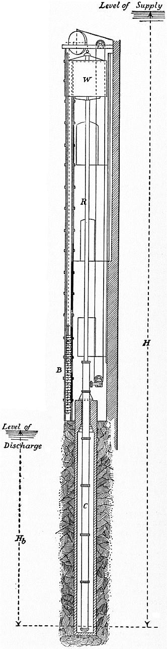
Fig. 171.
This shows that the efficiency increases with the pressure p, and diminishes with the speed v, other things being the same. If in regulating the engine for varying load the pressure is throttled, part of the available head is destroyed at the throttle valve, and p in the bracket above is reduced. Direct-acting hydraulic lifts, without intermediate gearing, may have an efficiency of 95% during the working stroke. If a hydraulic jigger is used with ropes and sheaves to change the speed of the ram to the speed of the lift, the efficiency may be only 50%. E. B. Ellington has given the efficiency of lifts with hydraulic balance at 85% during the working stroke. Large pressure engines have an efficiency of 85%, but small rotative engines probably not more than 50% and that only when fully loaded.
§ 176. Direct-Acting Hydraulic Lift (fig. 171).—This is the simplest of all kinds of hydraulic motor. A cage W is lifted directly by water pressure acting in a cylinder C, the length of which is a little greater than the lift. A ram or plunger R of the same length is attached to the cage. The water-pressure admitted by a cock to the cylinder forces up the ram, and when the supply valve is closed and the discharge valve opened, the ram descends. In this case the ram is 9 in. diameter, with a stroke of 49 ft. It consists of lengths of wrought-iron pipe screwed together perfectly water-tight, the lower end being closed by a cast-iron plug. The ram works in a cylinder 11 in. diameter of 9 ft. lengths of flanged cast-iron pipe. The ram passes water-tight through the cylinder cover, which is provided with double hat leathers to prevent leakage outwards or inwards. As the weight of the ram and cage is much more than sufficient to cause a descent of the cage, part of the weight is balanced. A chain attached to the cage passes over a pulley at the top of the lift, and carries at its free end a balance weight B, working in T iron guides. Water is admitted to the cylinder from a 4-in. supply pipe through a two-way slide, worked by a rack, spindle and endless rope. The lift works under 73 ft. of head, and lifts 1350 lb at 2 ft. per second. The efficiency is from 75 to 80%.
The principal prejudicial resistance to the motion of a ram of this kind is the friction of the cup leathers, which make the joint between the cylinder and ram. Some experiments by John Hick give for the friction of these leathers the following formula. Let F = the total friction in pounds; d = diameter of ram in ft.; p = water-pressure in pounds per sq. ft.; k a coefficient.
F = k p d
k = 0.00393 if the leathers are new or badly lubricated;
= 0.00262 if the leathers are in good condition and well lubricated.
Since the total pressure on the ram is P = 1⁄4πd2p, the fraction of the total pressure expended in overcoming the friction of the leathers is F/P = .005/d to .0033/d, d being in feet.
Let H be the height of the pressure column measured from the free surface of the supply reservoir to the bottom of the ram in its lowest position, Hb the height from the discharge reservoir to the same point, h the height of the ram above its lowest point at any moment, S the length of stroke, Ω the area of the ram, W the weight of cage, R the weight of ram, B the weight of balance weight, w the weight of balance chain per foot run, F the friction of the cup leather and slides. Then, neglecting fluid friction, if the ram is rising the accelerating force is
P1 = G (H − h) Ω − R − W + B − w (S − h) + wh − F,
and if the ram is descending
P2 = G (Hb − h) Ω + W + R − B + w (S − h) − wh − F.
If w = 1⁄2 GΩ, P1 and P2 are constant throughout the stroke; and the moving force in ascending and descending is the same, if
B = W + R + wS − GΩ (H + Hb) / 2.
Using the values just found for w and B,
P1 = P2 = 1⁄2 GΩ (H − Hb) − F.
Let W + R + wS + B = U, and let P be the constant accelerating force acting on the system, then the acceleration is (P/U)g. The velocity at the end of the stroke is (assuming the friction to be constant)
v = √ (2PgS / U);
and the mean velocity of ascent is 1⁄2v.
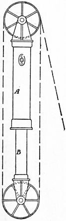
Fig. 172.
§ 177. Armstrong’s Hydraulic Jigger.—This is simply a single-acting hydraulic cylinder and ram, provided with sheaves so as to give motion to a wire rope or chain. It is used in various forms of lift and crane. Fig. 172 shows the arrangement. A hydraulic ram or plunger B works in a stationary cylinder A. Ram and cylinder carry sets of sheaves over which passes a chain or rope, fixed at one end to the cylinder, and at the other connected over guide pulleys to a lift or crane. For each pair of pulleys, one on the cylinder and one on the ram, the movement of the free end of the rope is doubled compared with that of the ram. With three pairs of pulleys the free end of the rope has a movement equal to six times the stroke of the ram, the force exerted being in the inverse proportion.
§ 178. Rotative Hydraulic Engines.—Valve-gear mechanism similar in principle to that of steam engines can be applied to actuate the admission and discharge valves, and the pressure engine is then converted into a continuously-acting motor.
Let H be the available fall to work the engine after deducting the loss of head in the supply and discharge pipes, Q the supply of water in cubic feet per second, and η the efficiency of the engine. Then the horse-power of the engine is
H.P. = ηGQH / 550.
The efficiency of large slow-moving pressure engines is η = .66 to .8. In small motors of this kind probably η is not greater than .5. Let v be the mean velocity of the piston, then its diameter d is given by the relation
Q = πd2v/4 in double-acting engines, = πd2v/8 in single-acting engines.
If there are n cylinders put Q/n for Q in these equations.
Small rotative pressure engines form extremely convenient motors for hoists, capstans or winches, and for driving small machinery. The single-acting engine has the advantage that the pressure of the piston on the crank pin is always in one direction; there is then no knocking as the dead centres are passed. Generally three single-acting cylinders are used, so that the engine will readily start in all positions, and the driving effort on the crank pin is very uniform.
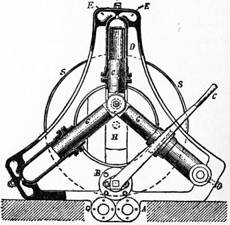
Fig. 173.
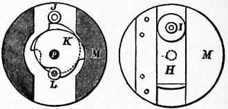
Fig. 174.
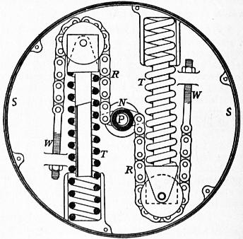
Fig. 175.
Brotherhood Hydraulic Engine.—Three cylinders at angles of 120° with each other are formed in one casting with the frame. The plungers are hollow trunks, and the connecting rods abut in cylindrical recesses in them and are connected to a common crank pin. A circular valve disk with concentric segmental ports revolves at the same rate as the crank over ports in the valve face common to the three cylinders. Each cylinder is always in communication with either an admission or exhaust port. The blank parts of the circular valve close the admission and exhaust ports alternately. The fixed valve face is of lignum vitae in a metal recess, and the revolving valve of gun-metal. In the case of a small capstan engine the cylinders are 31⁄2 in. diameter and 3 in. stroke. At 40 revs. per minute, the piston speed is 31 ft. per minute. The ports are 1 in. diameter or 1⁄12 of the piston area, and the mean velocity in the ports 6.4 ft. per sec. With 700 ℔ per sq. in. water pressure and an efficiency of 50%, the engine is about 3 h.p. A common arrangement is to have three parallel cylinders acting on a three-throw crank shaft, the cylinders oscillating on trunnions.
Hastie’s Engine.—Fig. 173 shows a similar engine made by Messrs Hastie of Greenock. G, G, G are the three plungers which pass out of the cylinders through cup leathers, and act on the same crank pin. A is the inlet pipe which communicates with the cock B. This cock controls the action of the engine, being so constructed that it acts as a reversing valve when the handle C is in its extreme positions and as a brake when in its middle position. With the handle in its middle position, the ports of the cylinders are in communication with the exhaust. Two passages are formed in the framing leading from the cock B to the ends of the cylinders, one being in communication with the supply pipe A, the other with the discharge pipe Q. These passages end as shown at E. The oscillation of the cylinders puts them alternately in communication with each of these passages, and thus the water is alternately admitted and exhausted.
In any ordinary rotative engine the length of stroke is invariable. Consequently the consumption of water depends simply on the speed of the engine, irrespective of the effort overcome. If the power of the engine must be varied without altering the number of rotations, then the stroke must be made variable. Messrs Hastie have contrived an exceedingly ingenious method of varying the stroke automatically, in proportion to the amount of work to be done (fig. 174). The crank pin I is carried in a slide H moving in a disk M. In this is a double cam K acting on two small steel rollers J, L attached to the slide H. If the cam rotates it moves the slide and increases or decreases the radius of the circle in which the crank pin I rotates. The disk M is keyed on a hollow shaft surrounding the driving shaft P, to which the cams are attached. The hollow shaft N has two snugs to which the chains RR are attached (fig. 175). The shaft P carries the spring case SS to which also are attached the other ends of the chains. When the engine is at rest the springs extend themselves, rotating the hollow shaft N and the frame M, so as to place the crank pin I at its nearest position to the axis of rotation. When a resistance has to be overcome, the shaft N rotates relatively to P, compressing the springs, till their resistance balances the pressure due to the resistance to the rotation of P. The engine then commences to work, the crank pin being in the position in which the turning effort just overcomes the resistance. If the resistance diminishes, the springs force out the chains and shorten the stroke of the plungers, and vice versa. The following experiments, on an engine of this kind working a hoist, show how the automatic arrangement adjusted the water used to the work done. The lift was 22 ft. and the water pressure in the cylinders 80 ℔ per sq. in.
Weight lifted, in ℔ Chain only 427 633 745 857 969 1081 1193
Water used, in gallons 71⁄2 10 14 16 17 20 21 22
§ 179. Accumulator Machinery.—It has already been pointed out that it is in some cases convenient to use a steam engine to create an artificial head of water, which is afterwards employed in driving water-pressure machinery. Where power is required intermittently, for short periods, at a number of different points, as, for instance, in moving the cranes, lock gates, &c., of a dockyard, a separate steam engine and boiler at each point is very inconvenient; nor can engines worked from a common boiler be used, because of the great loss of heat and the difficulties which arise out of condensation in the pipes. If a tank, into which water is continuously pumped, can be placed at a great elevation, the water can then be used in hydraulic machinery in a very convenient way. Each hydraulic machine is put in communication with the tank by a pipe, and on opening a valve it commences work, using a quantity of water directly proportional to the work done. No attendance is required when the machine is not working.
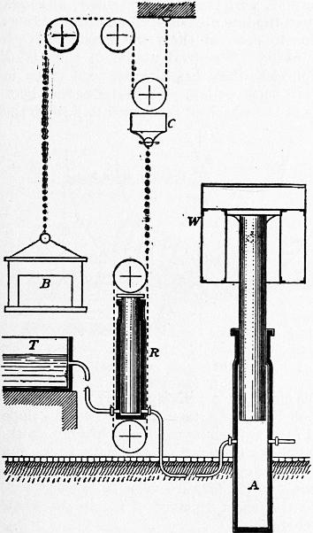
Fig. 176.
A site for such an elevated tank is, however, seldom available, and in place of it a beautiful arrangement termed an accumulator, invented by Lord Armstrong, is used. This consists of a tall vertical cylinder; into this works a solid ram through cup leathers or hemp packing, and the ram is loaded by fixed weights, so that the pressure in the cylinder is 700 ℔ or 800 ℔ per sq. in. In some cases the ram is fixed and the cylinder moves on it. The pumping engines which supply the energy that is stored in the accumulator should be a pair coupled at right angles, so as to start in any position. The engines pump into the accumulator cylinder till the ram is at the top of its stroke, when by a catch arrangement acting on the engine throttle valve the engines are stopped. If the accumulator ram descends, in consequence of water being taken to work machinery, the engines immediately recommence working. Pipes lead from the accumulator to each of the machines requiring to be driven, and do not require to be of large size, as the pressure is so great.
Fig. 176 shows a diagrammatic way the scheme of a system of accumulator machinery. A is the accumulator, with its ram carrying a cylindrical wrought-iron tank W, in which weights are placed to load the accumulator. At R is one of the pressure engines or jiggers, worked from the accumulator, discharging the water after use into the tank T. In this case the pressure engine is shown working a set of blocks, the fixed block being on the ram cylinder, the running block on the ram. The chain running over these blocks works a lift cage C, the speed of which is as many times greater than that of the ram as there are plies of chain on the block tackle. B is the balance weight of the cage.
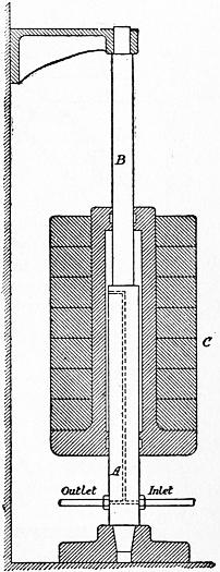
Fig. 177.
In the use of accumulators on shipboard for working gun gear or steering gear, the accumulator ram is loaded by springs, or by steam pressure acting on a piston much larger than the ram.
R. H. Tweddell has used accumulators with a pressure of 2000 ℔ per sq. in. to work hydraulic riveting machinery.
The amount of energy stored in the accumulator, having a ram d in. in diameter, a stroke of S ft., and delivering at p ℔ pressure per sq. in., is
π/4 p d2S foot-pounds.
Thus, if the ram is 9 in., the stroke 20 ft., and the pressure 800 ℔ per sq. in., the work stored in the accumulator when the ram is at the top of the stroke is 1,017,600 foot-pounds, that is, enough to drive a machine requiring one horse power for about half an hour. As, however, the pumping engine replaces water as soon as it is drawn off, the working capacity of the accumulator is very much greater than this. Tweddell found that an accumulator charged at 1250 ℔ discharged at 1225 ℔ per sq. in. Hence the friction was equivalent to 121⁄2 ℔ per sq. in. and the efficiency 98%.
When a very great pressure is required a differential accumulator (fig. 177) is convenient. The ram is fixed and passes through both ends of the cylinder, but is of different diameters at the two ends, A and B. Hence if d1, d2 are the diameters of the ram in inches and p the required pressure in ℔ per sq. in., the load required is 1⁄4pπ(d12 − d22). An accumulator of this kind used with riveting machines has d1 = 51⁄2 in., d2 = 43⁄4 in. The pressure is 2000 ℔ per sq. in. and the load 5.4 tons.
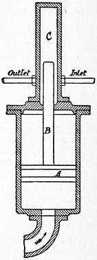
Fig. 178.
Sometimes an accumulator is loaded by water or steam pressure instead of by a dead weight. Fig. 178 shows the arrangement. A piston A is connected to a plunger B of much smaller area. Water pressure, say from town mains, is admitted below A, and the high pressure water is pumped into and discharged from the cylinder C in which B works. If r is the ratio of the areas of A and B, then, neglecting friction, the pressure in the upper cylinder is r times that under the piston A. With a variable rate of supply and demand from the upper cylinder, the piston A rises and falls, maintaining always a constant pressure in the upper cylinder.
Water Wheels.
§ 180. Overshot and High Breast Wheels.—When a water fall ranges between 10 and 70 ft. and the water supply is from 3 to 25 cub. ft. per second, it is possible to construct a bucket wheel on which the water acts chiefly by its weight. If the variation of the head-water level does not exceed 2 ft., an overshot wheel may be used (fig. 179). The water is then projected over the summit of the wheel, and falls in a parabolic path into the buckets. With greater variation of head-water level, a pitch-back or high breast wheel is better. The water falls over the top of a sliding sluice into the wheel, on the same side as the head race channel. By adjusting the height of the sluice, the requisite supply is given to the wheel in all positions of the head-water level.
The wheel consists of a cast-iron or wrought-iron axle C supporting the weight of the wheel. To this are attached two sets of arms A of wood or iron, which support circular segmental plates, B, termed shrouds. A cylindrical sole plate dd extends between the shrouds on the inner side. The buckets are formed by wood planks or curved wrought-iron plates extending from shroud to shroud, the back of the buckets being formed by the sole plate.
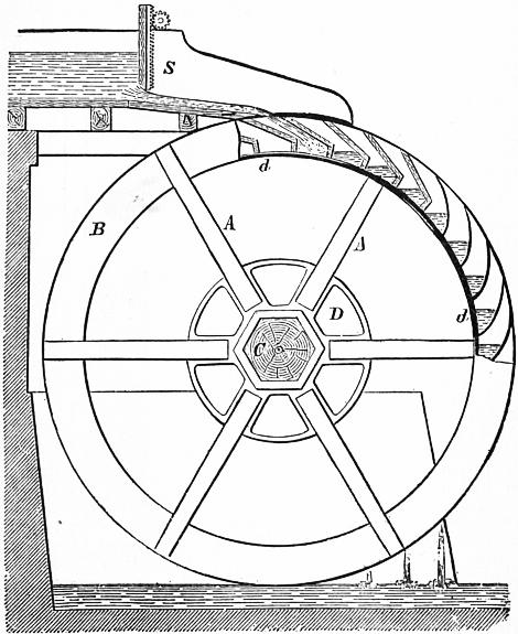
Fig. 179.
The efficiency may be taken at 0.75. Hence, if h.p. is the effective horse power, H the available fall, and Q the available water supply per second,
h.p. = 0.75 (GQH/550) = 0.085 QH.
If the peripheral velocity of the water wheel is too great, water is thrown out of the buckets before reaching the bottom of the fall. In practice, the circumferential velocity of water wheels of the kind now described is from 41⁄2 to 10 ft. per second, about 6 ft. being the usual velocity of good iron wheels not of very small size. In order that the water may enter the buckets easily, it must have a greater velocity than the wheel. Usually the velocity of the water at the point where it enters the wheel is from 9 to 12 ft. per second, and to produce this it must enter the wheel at a point 16 to 27 in. below the head-water level. Hence the diameter of an overshot wheel may be
D = H − 11⁄3 to H − 21⁄4 ft.
Overshot and high breast wheels work badly in backwater, and hence if the tail-water level varies, it is better to reduce the diameter of the wheel so that its greatest immersion in flood is not more than 1 ft. The depth d of the shrouds is about 10 to 16 in. The number of buckets may be about
N = πD / d.
Let v be the peripheral velocity of the wheel. Then the capacity of that portion of the wheel which passes the sluice in one second is
Q1 = vb (Dd − d2) / D = v b d nearly,
b being the breadth of the wheel between the shrouds. If, however, this quantity of water were allowed to pass on to the wheel the buckets would begin to spill their contents almost at the top of the fall. To diminish the loss from spilling, it is not only necessary to give the buckets a suitable form, but to restrict the water supply to one-fourth or one-third of the gross bucket capacity. Let m be the value of this ratio; then, Q being the supply of water per second,
Q = mQ1 = mb dv.
This gives the breadth of the wheel if the water supply is known. The form of the buckets should be determined thus. The outer element of the bucket should be in the direction of motion of the water entering relatively to the wheel, so that the water may enter without splashing or shock. The buckets should retain the water as long as possible, and the width of opening of the buckets should be 2 or 3 in. greater than the thickness of the sheet of water entering.
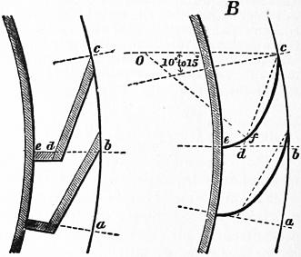
Fig. 180.
For a wooden bucket (fig. 180, A), take ab = distance between two buckets on periphery of wheel. Make ed = 1⁄2 eb and bc = 6⁄5 to 5⁄4 ab. Join cd. For an iron bucket (fig. 180, B), take ed = 1⁄3eb; bc = 6⁄5ab. Draw cO making an angle of 10° to 15° with the radius at c. On Oc take a centre giving a circular arc passing near d, and round the curve into the radial part of the bucket de.
There are two ways in which the power of a water wheel is given off to the machinery driven. In wooden wheels and wheels with rigid arms, a spur or bevil wheel keyed on the axle of the turbine will transmit the power to the shafting. It is obvious that the whole turning moment due to the weight of the water is then transmitted through the arms and axle of the water wheel. When the water wheel is an iron one, it usually has light iron suspension arms incapable of resisting the bending action due to the transmission of the turning effort to the axle. In that case spur segments are bolted to one of the shrouds, and the pinion to which the power is transmitted is placed so that the teeth in gear are, as nearly as may be, on the line of action of the resultant of the weight of the water in the loaded arc of the wheel.
The largest high breast wheels ever constructed were probably the four wheels, each 50 ft. in diameter, and of 125 h.p., erected by Sir W. Fairbairn in 1825 at Catrine in Ayrshire. These wheels are still working.
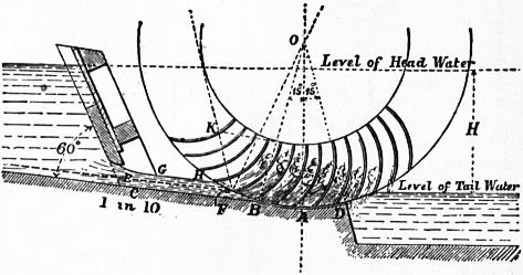
Fig. 181.
§ 181. Poncelet Water Wheel.—When the fall does not exceed 6 ft., the best water motor to adopt in many cases is the Poncelet undershot water wheel. In this the water acts very nearly in the same way as in a turbine, and the Poncelet wheel, although slightly less efficient than the best turbines, in normal conditions of working, is superior to most of them when working with a reduced supply of water. A general notion of the action of the water on a Poncelet wheel has already been given in § 159. Fig. 181 shows its construction. The water penned back between the side walls of the wheel pit is allowed to flow to the wheel under a movable sluice, at a velocity nearly equal to the velocity due to the whole fall. The water is guided down a slope of 1 in 10, or a curved race, and enters the wheel without shock. Gliding up the curved floats it comes to rest, falls back, and acquires at the point of discharge a backward velocity relative to the wheel nearly equal to the forward velocity of the wheel. Consequently it leaves the wheel deprived of nearly the whole of its original kinetic energy.
Taking the efficiency at 0.60, and putting H for the available fall, h.p. for the horse-power, and Q for the water supply per second,
h.p. = 0.068 QH.
The diameter D of the wheel may be taken arbitrarily. It should not be less than twice the fall and is more often four times the fall. For ordinary cases the smallest convenient diameter is 14 ft. with a straight, or 10 ft. with a curved, approach channel. The radial depth of bucket should be at least half the fall, and radius of curvature of buckets about half the radius of the wheel. The shrouds are usually of cast iron with flanges to receive the buckets. The buckets may be of iron 1⁄8 in. thick bolted to the flanges with 5⁄16 in. bolts.
Let H′ be the fall measured from the free surface of the head-water to the point F where the mean layer enters the wheel; then the velocity at which the water enters is v = √ (2gH′), and the best circumferential velocity of the wheel is V = 0.55f to 0.6v. The number of rotations of the wheel per second is N = V/πD. The thickness of the sheet of water entering the wheel is very important. The best thickness according to experiment is 8 to 10 in. The maximum thickness should not exceed 12 to 15 in., when there is a surplus water supply. Let e be the thickness of the sheet of water entering the wheel, and b its width; then
bev = Q; or b = Q/ev.
Grashof takes e = 1⁄6H, and then
b = 6Q/H √ (2gH).
Allowing for the contraction of the stream, the area of opening through the sluice may be 1.25 be to 1.3 be. The inside width of the wheel is made about 4 in. greater than b.
Several constructions have been given for the floats of Poncelet wheels. One of the simplest is that shown in figs. 181, 182.
Let OA (fig. 181) be the vertical radius of the wheel. Set off OB, OD making angles of 15° with OA. Then BD may be the length of the close breasting fitted to the wheel. Draw the bottom of the head face BC at a slope of 1 in 10. Parallel to this, at distances 1⁄2e and e, draw EF and GH. Then EF is the mean layer and GH the surface layer entering the wheel. Join OF, and make OFK = 23°. Take FK = 0.5 to 0.7 H. Then K is the centre from which the bucket curve is struck and KF is the radius. The depth of the shrouds must be sufficient to prevent the water from rising over the top of the float. It is 1⁄2H to 2⁄3H. The number of buckets is not very important. They are usually 1 ft. apart on the circumference of the wheel.
The efficiency of a Poncelet wheel has been found in experiments to reach 0.68. It is better to take it at 0.6 in estimating the power of the wheel, so as to allow some margin.
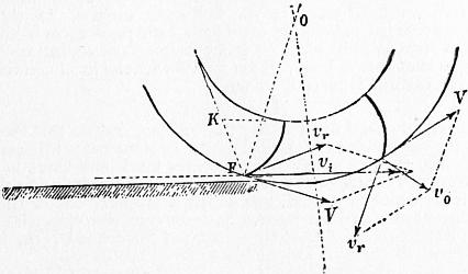
Fig. 182.
In fig. 182 vi is the initial and vo the final velocity of the water, vr parallel to the vane the relative velocity of the water and wheel, and V the velocity of the wheel.
Turbines.
§ 182. The name turbine was originally given in France to any water motor which revolved in a horizontal plane, the axis being vertical. The rapid development of this class of motors dates from 1827, when a prize was offered by the Société d’Encouragement for a motor of this kind, which should be an improvement on certain wheels then in use. The prize was ultimately awarded to Benoît Fourneyron (1802-1867), whose turbine, but little modified, is still constructed.
Classification of Turbines.—In some turbines the whole available energy of the water is converted into kinetic energy before the water acts on the moving part of the turbine. Such turbines are termed Impulse or Action Turbines, and they are distinguished by this that the wheel passages are never entirely filled by the water. To ensure this condition they must be placed a little above the tail water and discharge into free air. Turbines in which part only of the available energy is converted into kinetic energy before the water enters the wheel are termed Pressure or Reaction Turbines. In these there is a pressure which in some cases amounts to half the head in the clearance space between the guide vanes and wheel vanes. The velocity with which the water enters the wheel is due to the difference between the pressure due to the head and the pressure in the clearance space. In pressure turbines the wheel passages must be continuously filled with water for good efficiency, and the wheel may be and generally is placed below the tail water level.
Some turbines are designed to act normally as impulse turbines discharging above the tail water level. But the passages are so designed that they are just filled by the water. If the tail water rises and drowns the turbine they become pressure turbines with a small clearance pressure, but the efficiency is not much affected. Such turbines are termed Limit turbines.
Next there is a difference of constructive arrangement of turbines, which does not very essentially alter the mode of action of the water. In axial flow or so-called parallel flow turbines, the water enters and leaves the turbine in a direction parallel to the axis of rotation, and the paths of the molecules lie on cylindrical surfaces concentric with that axis. In radial outward and inward flow turbines, the water enters and leaves the turbine in directions normal to the axis of rotation, and the paths of the molecules lie exactly or nearly in planes normal to the axis of rotation. In outward flow turbines the general direction of flow is away from the axis, and in inward flow turbines towards the axis. There are also mixed flow turbines in which the water enters normally and is discharged parallel to the axis of rotation.
Another difference of construction is this, that the water may be admitted equally to every part of the circumference of the turbine wheel or to a portion of the circumference only. In the former case, the condition of the wheel passages is always the same; they receive water equally in all positions during rotation. In the latter case, they receive water during a part of the rotation only. The former may be termed turbines with complete admission, the latter turbines with partial admission. A reaction turbine should always have complete admission. An impulse turbine may have complete or partial admission.
When two turbine wheels similarly constructed are placed on the same axis, in order to balance the pressures and diminish journal friction, the arrangement may be termed a twin turbine.
If the water, having acted on one turbine wheel, is then passed through a second on the same axis, the arrangement may be termed a compound turbine. The object of such an arrangement would be to diminish the speed of rotation.
Many forms of reaction turbine may be placed at any height not exceeding 30 ft. above the tail water. They then discharge into an air-tight suction pipe. The weight of the column of water in this pipe balances part of the atmospheric pressure, and the difference of pressure, producing the flow through the turbine, is the same as if the turbine were placed at the bottom of the fall.
I. Impulse Turbines. II. Reaction Turbines.
(Wheel passages not filled, and discharging above (Wheel passages filled, discharging above or below
the tail water.) the tail water or into a suction-pipe.
(a) Complete admission. (Rare.) Always with complete admission.
(b) Partial admission. (Usual.)
Axial flow, outward flow, inward flow, or mixed flow.
Simple turbines; twin turbines; compound turbines.
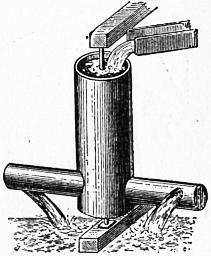
Fig. 183.
§ 183. The Simple Reaction Wheel.—It has been shown, in § 162, that, when water issues from a vessel, there is a reaction on the vessel tending to cause motion in a direction opposite to that of the jet. This principle was applied in a rotating water motor at a very early period, and the Scotch turbine, at one time much used, differs in no essential respect from the older form of reaction wheel.
The old reaction wheel consisted of a vertical pipe balanced on a vertical axis, and supplied with water (fig. 183). From the bottom of the vertical pipe two or more hollow horizontal arms extended, at the ends of which were orifices from which the water was discharged. The reaction of the jets caused the rotation of the machine.
Let H be the available fall measured from the level of the water in the vertical pipe to the centres cf the orifices, r the radius from the axis of rotation to the centres of the orifices, v the velocity of discharge through the jets, α the angular velocity of the machine. When the machine is at rest the water issues from the orifices with the velocity √ (2gH) (friction being neglected). But when the machine rotates the water in the arms rotates also, and is in the condition of a forced vortex, all the particles having the same angular velocity. Consequently the pressure in the arms at the orifices is H + α2r2/2g ft. of water, and the velocity of discharge through the orifices is v = √ (2gH + α2r2). If the total area of the orifices is ω, the quantity discharged from the wheel per second is
Q = ωv = ω √ (2gH + α2r2).
While the water passes through the orifices with the velocity v, the orifices are moving in the opposite direction with the velocity αr. The absolute velocity of the water is therefore
v − αr = √ (2gH + α2r2) − αr.
The momentum generated per second is (GQ/g)(v − αr), which is numerically equal to the force driving the motor at the radius r. The work done by the water in rotating the wheel is therefore
(GQ/g) (v − αr) αr foot-pounds per sec.
The work expended by the water fall is GQH foot-pounds per second. Consequently the efficiency of the motor is
η = (v − αr) αr = {√ (2gH + α2r2) − αr} αr .
gH gH
Let
√ (2gH + α2r2) = αr + gH − g2H2 ...
αr 2α3r3
then
η = 1 − gH / 2αr + ...
which increases towards the limit 1 as αr increases towards infinity. Neglecting friction, therefore, the maximum efficiency is reached when the wheel has an infinitely great velocity of rotation. But this condition is impracticable to realize, and even, at practicable but high velocities of rotation, the friction would considerably reduce the efficiency. Experiment seems to show that the best efficiency is reached when αr = √ (2gH). Then the efficiency apart from friction is
η = {√ (2α2r2) − αr} αr / gH = 0.414 α2r2 / gH = 0.828,
about 17% of the energy of the fall being carried away by the water discharged. The actual efficiency realized appears to be about 60%, so that about 21% of the energy of the fall is lost in friction, in addition to the energy carried away by the water.
§ 184. General Statement of Hydrodynamical Principles necessary for the Theory of Turbines.
(a) When water flows through any pipe-shaped passage, such as the passage between the vanes of a turbine wheel, the relation between the changes of pressure and velocity is given by Bernoulli’s theorem (§ 29). Suppose that, at a section A of such a passage, h1 is the pressure measured in feet of water, v1 the velocity, and z1 the elevation above any horizontal datum plane, and that at a section B the same quantities are denoted by h2, v2, z2. Then
h1 − h2 = (v22 − v12) / 2g + z2 − z1.
(1)
If the flow is horizontal, z2 = z1; and
h1 − h2 = (v22 − v12) / 2g. (la)
(b) When there is an abrupt change of section of the passage, or an abrupt change of section of the stream due to a contraction, then, in applying Bernoulli’s equation allowance must be made for the loss of head in shock (§ 36). Let v1, v2 be the velocities before and after the abrupt change, then a stream of velocity v1 impinges on a stream at a velocity v2, and the relative velocity is v1 − v2. The head lost is (v1 − v2)2/2g. Then equation (1a) becomes
h2 − h1 = (v12 − v22) / 2g − (v1 − v2)2 / 2g = v2 (v1 − v2) / g
(2)
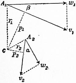
Fig. 184.
To diminish as much as possible the loss of energy from irregular eddying motions, the change of section in the turbine passages must be very gradual, and the curvature without discontinuity.
(c) Equality of Angular Impulse and Change of Angular Momentum.—Suppose that a couple, the moment of which is M, acts on a body of weight W for t seconds, during which it moves from A1 to A2 (fig. 184). Let v1 be the velocity of the body at A1, v2 its velocity at A2, and let p1, p2 be the perpendiculars from C on v1 and v2. Then Mt is termed the angular impulse of the couple, and the quantity
(W/g) (v2p2 − v1p1)
is the change of angular momentum relatively to C. Then, from the equality of angular impulse and change of angular momentum
Mt = (W/g) (v2p2 − v1p1),
or, if the change of momentum is estimated for one second,
M = (W/g) (v2p2 − v1p1).
Let r1, r2 be the radii drawn from C to A1, A2, and let w1, w2 be the components of v1, v2, perpendicular to these radii, making angles β and α with v1, v2. Then
v1 = w1 sec β; v2 = w2 sec α
p1 = r1 cos β; p2 = r2 cos α,
∴ M = (W/g) (w2r2 − w1r1),
(3)
where the moment of the couple is expressed in terms of the radii drawn to the positions of the body at the beginning and end of a second, and the tangential components of its velocity at those points.
Now the water flowing through a turbine enters at the admission surface and leaves at the discharge surface of the wheel, with its angular momentum relatively to the axis of the wheel changed. It therefore exerts a couple −M tending to rotate the wheel, equal and opposite to the couple M which the wheel exerts on the water. Let Q cub. ft. enter and leave the wheel per second, and let w1, w2 be the tangential components of the velocity of the water at the receiving and discharging surfaces of the wheel, r1, r2 the radii of those surfaces. By the principle above,
−M = (GQ/g) (w2r2 − w1r1).
(4)
If α is the angular velocity of the wheel, the work done by the water on the wheel is
T = Ma = (GQ/g) (w1r1 − w2r2) α foot-pounds per second.
(5)
§ 185. Total and Available Fall.—Let Ht be the total difference of level from the head-water to the tail-water surface. Of this total head a portion is expended in overcoming the resistances of the head race, tail race, supply pipe, or other channel conveying the water. Let ɧp be that loss of head, which varies with the local conditions in which the turbine is placed. Then
H = Ht − ɧp
is the available head for working the turbine, and on this the calculations for the turbine should be based. In some cases it is necessary to place the turbine above the tail-water level, and there is then a fall ɧ from the centre of the outlet surface of the turbine to the tail-water level which is wasted, but which is properly one of the losses belonging to the turbine itself. In that case the velocities of the water in the turbine should be calculated for a head H − ɧ, but the efficiency of the turbine for the head H.
§ 186. Gross Efficiency and Hydraulic Efficiency of a Turbine.—Let Td be the useful work done by the turbine, in foot-pounds per second, Tt the work expended in friction of the turbine shaft, gearing, &c., a quantity which varies with the local conditions in which the turbine is placed. Then the effective work done by the water in the turbine is
T = Td + Tt.
The gross efficiency of the whole arrangement of turbine, races, and transmissive machinery is
ηt = Td / CQHt.
(6)
And the hydraulic efficiency of the turbine alone is
η = T / GQH.
(7)
It is this last efficiency only with which the theory of turbines is concerned.
From equations (5) and (7) we get
ηGQH = (GQ/g) (w1r1 − w2r2) α;
η = (w1r1 − w2r2) α/gH.
(8)
This is the fundamental equation in the theory of turbines. In general,7 w1 and w2, the tangential components of the water’s motion on entering and leaving the wheel, are completely independent. That the efficiency may be as great as possible, it is obviously necessary that w2 = 0. In that case
η = w1r1α / gH.
(9)
αr1 is the circumferential velocity of the wheel at the inlet surface. Calling this V1, the equation becomes
η = w1V1 / gH.
(9a)
This remarkably simple equation is the fundamental equation in the theory of turbines. It was first given by Reiche (Turbinenbaues, 1877).
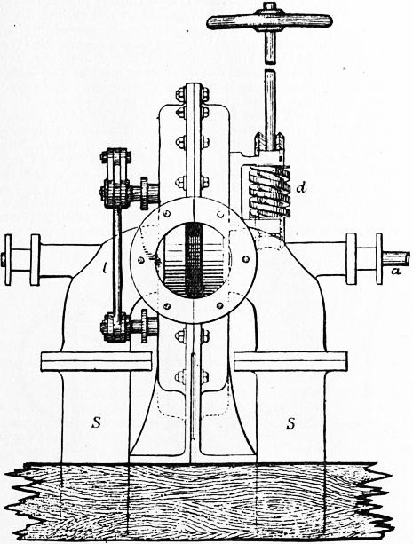
Fig. 185.
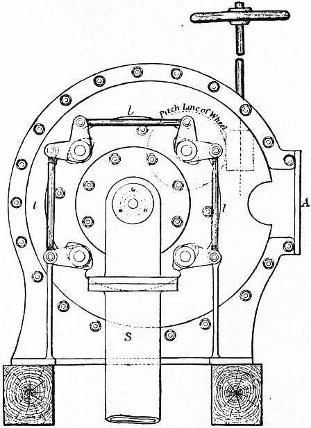
Fig. 186.
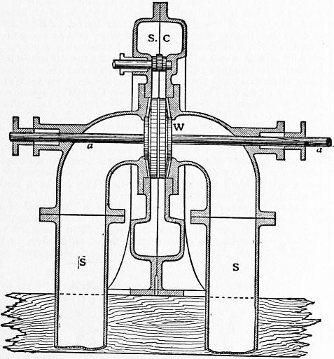
Fig. 187.
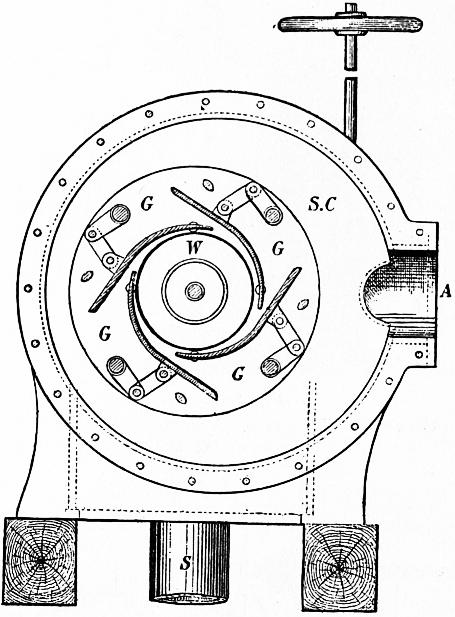
Fig. 188.
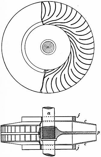
Fig. 189.
§ 187. General Description of a Reaction Turbine.—Professor James Thomson’s inward flow or vortex turbine has been selected as the type of reaction turbines. It is one of the best in normal conditions of working, and the mode of regulation introduced is decidedly superior to that in most reaction turbines. Figs. 185 and 186 are external views of the turbine case; figs. 187 and 188 are the corresponding sections; fig. 189 is the turbine wheel. The example chosen for illustration has suction pipes, which permit the turbine to be placed above the tail-water level. The water enters the turbine by cast-iron supply pipes at A, and is discharged through two suction pipes S, S. The water on entering the case distributes itself through a rectangular supply chamber SC, from which it finds its way equally to the four guide-blade passages G, G, G, G. In these passages it acquires a velocity about equal to that due to half the fall, and is directed into the wheel at an angle of about 10° or 12° with the tangent to its circumference. The wheel W receives the water in equal proportions from each guide-blade passage. It consists of a centre plate p (fig. 189) keyed on the shaft aa, which passes through stuffing boxes on the suction pipes. On each side of the centre plate are the curved wheel vanes, on which the pressure of the water acts, and the vanes are bounded on each side by dished or conical cover plates c, c. Joint-rings j, j on the cover plates make a sufficiently water-tight joint with the casing, to prevent leakage from the guide-blade chamber into the suction pipes. The pressure near the joint rings is not very great, probably not one-fourth the total head. The wheel vanes receive the water without shock, and deliver it into central spaces, from which it flows on either side to the suction pipes. The mode of regulating the power of the turbine is very simple. The guide-blades are pivoted to the case at their inner ends, and they are connected by a link-work, so that they all open and close simultaneously and equally. In this way the area of opening through the guide-blades is altered without materially altering the angle or the other conditions of the delivery into the wheel. The guide-blade gear may be variously arranged. In this example four spindles, passing through the case, are linked to the guide-blades inside the case, and connected together by the links l, l, l on the outside of the case. A worm wheel on one of the spindles is rotated by a worm d, the motion being thus slow enough to adjust the guide-blades very exactly. These turbines are made by Messrs Gilkes & Co. of Kendal.
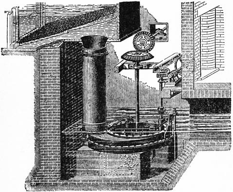
Fig. 190.
Fig. 190 shows another arrangement of a similar turbine, with some adjuncts not shown in the other drawings. In this case the turbine rotates horizontally, and the turbine case is placed entirely below the tail water. The water is supplied to the turbine by a vertical pipe, over which is a wooden pentrough, containing a strainer, which prevents sticks and other solid bodies getting into the turbine. The turbine rests on three foundation stones, and, the pivot for the vertical shaft being under water, there is a screw and lever arrangement for adjusting it as it wears. The vertical shaft gives motion to the machinery driven by a pair of bevel wheels. On the right are the worm and wheel for working the guide-blade gear.
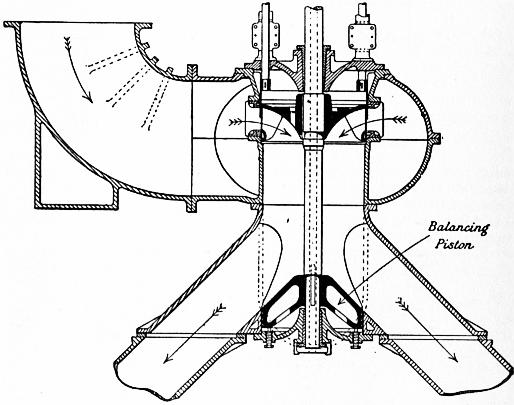
Fig. 191.
§ 188. Hydraulic Power at Niagara.—The largest development of hydraulic power is that at Niagara. The Niagara Falls Power Company have constructed two power houses on the United States side, the first with 10 turbines of 5000 h.p. each, and the second with 10 turbines of 5500 h.p. The effective fall is 136 to 140 ft. In the first power house the turbines are twin outward flow reaction turbines with vertical shafts running at 250 revs. per minute and driving the dynamos direct. In the second power house the turbines are inward flow turbines with draft tubes or suction pipes. Fig. 191 shows a section of one of these turbines. There is a balancing piston keyed on the shaft, to the under side of which the pressure due to the fall is admitted, so that the weight of turbine, vertical shaft and part of the dynamo is water borne. About 70,000 h.p. is daily distributed electrically from these two power houses. The Canadian Niagara Power Company are erecting a power house to contain eleven units of 10,250 h.p. each, the turbines being twin inward flow reaction turbines. The Electrical Development Company of Ontario are erecting a power house to contain 11 units of 12,500 h.p. each. The Ontario Power Company are carrying out another scheme for developing 200,000 h.p. by twin inward flow turbines of 12,000 h.p. each. Lastly the Niagara Falls Power and Manufacturing Company on the United States side have a station giving 35,000 h.p. and are constructing another to furnish 100,000 h.p. The mean flow of the Niagara river is about 222,000 cub. ft. per second with a fall of 160 ft. The works in progress if completed will utilize 650,000 h.p. and require 48,000 cub. ft. per second or 211⁄2% of the mean flow of the river (Unwin, “The Niagara Falls Power Stations,” Proc. Inst. Mech. Eng., 1906).
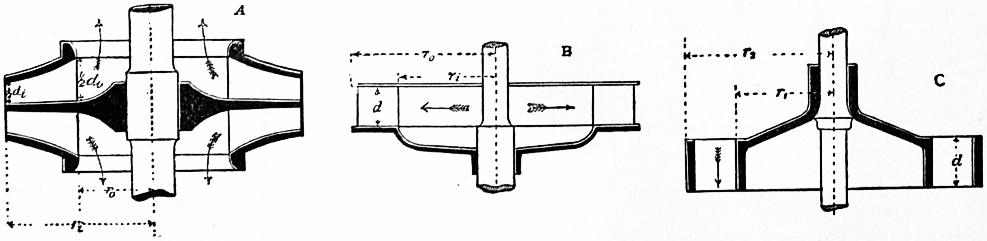
Fig. 192.
§ 189. Different Forms of Turbine Wheel.—The wheel of a turbine or part of the machine on which the water acts is an annular space, furnished with curved vanes dividing it into passages exactly or roughly rectangular in cross section. For radial flow turbines the wheel may have the form A or B, fig. 192, A being most usual with inward, and B with outward flow turbines. In A the wheel vanes are fixed on each side of a centre plate keyed on the turbine shaft. The vanes are limited by slightly-coned annular cover plates. In B the vanes are fixed on one side of a disk, keyed on the shaft, and limited by a cover plate parallel to the disk. Parallel flow or axial flow turbines have the wheel as in C. The vanes are limited by two concentric cylinders.
Theory of Reaction Turbines.
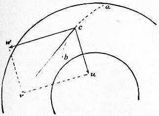
Fig. 193.
§ 190. Velocity of Whirl and Velocity of Flow.—Let acb (fig. 193) be the path of the particles of water in a turbine wheel. That path will be in a plane normal to the axis of rotation in radial flow turbines, and on a cylindrical surface in axial flow turbines. At any point c of the path the water will have some velocity v, in the direction of a tangent to the path. That velocity may be resolved into two components, a whirling velocity w in the direction of the wheel’s rotation at the point c, and a component u at right angles to this, radial in radial flow, and parallel to the axis in axial flow turbines. This second component is termed the velocity of flow. Let vo, wo, uo be the velocity of the water, the whirling velocity and velocity of flow at the outlet surface of the wheel, and vi, wi, ui the same quantities at the inlet surface of the wheel. Let α and β be the angles which the water’s direction of motion makes with the direction of motion of the wheel at those surfaces. Then
wo = vo cos β; uo = vo sin β wi = vi cos α; ui = vi sin α.
(10)
The velocities of flow are easily ascertained independently from the dimensions of the wheel. The velocities of flow at the inlet and outlet surfaces of the wheel are normal to those surfaces. Let Ωo, Ωi be the areas of the outlet and inlet surfaces of the wheel, and Q the volume of water passing through the wheel per second; then
v0 = Q/Ωo; vi = Q/Ωi.
(11)
Using the notation in fig. 191, we have, for an inward flow turbine (neglecting the space occupied by the vanes),
Ωo = 2πr0d0; Ωi = 2πridi.
(12a)
Similarly, for an outward flow turbine,
Ωo = 2πrod; Ωi = 2πrid;
(12b)
and, for an axial flow turbine,
Ωo = Ωi = π (r22 − r12).
(12c)
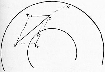
Fig. 194.
Relative and Common Velocity of the Water and Wheel.—There is another way of resolving the velocity of the water. Let V be the velocity of the wheel at the point c, fig. 194. Then the velocity of the water may be resolved into a component V, which the water has in common with the wheel, and a component vr, which is the velocity of the water relatively to the wheel.
Velocity of Flow.—It is obvious that the frictional losses of head in the wheel passages will increase as the velocity of flow is greater, that is, the smaller the wheel is made. But if the wheel works under water, the skin friction of the wheel cover increases as the diameter of the wheel is made greater, and in any case the weight of the wheel and consequently the journal friction increase as the wheel is made larger. It is therefore desirable to choose, for the velocity of flow, as large a value as is consistent with the condition that the frictional losses in the wheel passages are a small fraction of the total head.
The values most commonly assumed in practice are these:—
In axial flow turbines, uo = ui = 0.15 to 0.2 √(2gH);
In outward flow turbines, ui = 0.25 √2g (H − ɧ),
uo = 0.21 to 0.17 √2g (H − ɧ);
In inward flow turbines, uo = ui = 0.125 √(2gH).
§ 191. Speed of the Wheel.—The best speed of the wheel depends partly on the frictional losses, which the ordinary theory of turbines disregards. It is best, therefore, to assume for Vo and Vi values which experiment has shown to be most advantageous.
In axial flow turbines, the circumferential velocities at the mean radius of the wheel may be taken
Vo = Vi = 0.6 √2gH to 0.66 √2gH.
In a radial outward flow turbine,
Vi = 0.56 √2g(H − ɧ)
Vo = Viro / ri,
where ro, ri are the radii of the outlet and inlet surfaces.
In a radial inward flow turbine,
Vi = 0.66 √2gH,
Vo = Viro / ri.
If the wheel were stationary and the water flowed through it, the water would follow paths parallel to the wheel vane curves, at least when the vanes were so close that irregular motion was prevented. Similarly, when the wheel is in motion, the water follows paths relatively to the wheel, which are curves parallel to the wheel vanes. Hence the relative component, vr, of the water’s motion at c is tangential to a wheel vane curve drawn through the point c. Let vo, Vo, vro be the velocity of the water and its common and relative components at the outlet surface of the wheel, and vi, Vi, vri be the same quantities at the inlet surface; and let θ and φ be the angles the wheel vanes make with the inlet and outlet surfaces; then
vo2 = √ (vro2 + Vo2 − 2Vovro cos φ) vi = √ (vri2 + Vo2 − 2Vivri cos θ),
(13)
equations which may be used to determine φ and θ.
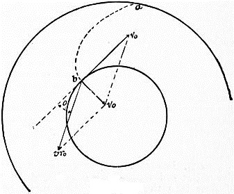
Fig. 195.
§ 192. Condition determining the Angle of the Vanes at the Outlet Surface of the Wheel.—It has been shown that, when the water leaves the wheel, it should have no tangential velocity, if the efficiency is to be as great as possible; that is, wo = 0. Hence, from (10), cos β = 0, β = 90°, Uo = Vo, and the direction of the water’s motion is normal to the outlet surface of the wheel, radial in radial flow, and axial in axial flow turbines.
Drawing vo or uo radial or axial as the case may be, and Vo tangential to the direction of motion, vro can be found by the parallelogram of velocities. From fig. 195,
tan φ = vo / Vo = uo / Vo;
(14)
but φ is the angle which the wheel vane makes with the outlet surface of the wheel, which is thus determined when the velocity of flow uo and velocity of the wheel Vo are known. When φ is thus determined,
vro = Uo cosec φ = Vo √ (1 + uo2 / Vo2).
(14a)
Correction of the Angle φ to allow for Thickness of Vanes.—In determining φ, it is most convenient to calculate its value approximately at first, from a value of uo obtained by neglecting the thickness of the vanes. As, however, this angle is the most important angle in the turbine, the value should be afterwards corrected to allow for the vane thickness.
Let
φ′ = tan−1 (uo / Vo) = tan−1 (Q / ΩoVo)
be the first or approximate value of φ, and let t be the thickness, and n the number of wheel vanes which reach the outlet surface of the wheel. As the vanes cut the outlet surface approximately at the angle φ′, their width measured on that surface is t cosec φ′. Hence the space occupied by the vanes on the outlet surface is
For A, fig. 192, ntdo cosec φ B, fig. 192, ntd cosec φ C, fig. 192, nt (r2 − r1) cosec φ.
(15)
Call this area occupied by the vanes ω. Then the true value of the clear discharging outlet of the wheel is Ωo − ω, and the true value of uo is Q/(Ωo − ω). The corrected value of the angle of the vanes will be
φ = tan [Q / Vo (Ωo − ω) ].
(16)
§ 193. Head producing Velocity with which the Water enters the Wheel.—Consider the variation of pressure in a wheel passage, which satisfies the condition that the sections change so gradually that there is no loss of head in shock. When the flow is in a horizontal plane, there is no work done by gravity on the water passing through the wheel. In the case of an axial flow turbine, in which the flow is vertical, the fall d between the inlet and outlet surfaces should be taken into account.
Let Vi, Vo be the velocities of the wheel at the inlet and outlet surfaces, vi, vo the velocities of the water, ui, uo the velocities of flow, vri, vro the relative velocities, hi, ho the pressures, measured in feet of water, ri, ro the radii of the wheel, α the angular velocity of the wheel.
At any point in the path of a portion of water, at radius r, the velocity v of the water may be resolved into a component V = αr equal to the velocity at that point of the wheel, and a relative component vr. Hence the motion of the water may be considered to consist of two parts:—(a) a motion identical with that in a forced vortex of constant angular velocity α; (b) a flow along curves parallel to the wheel vane curves. Taking the latter first, and using Bernoulli’s theorem, the change of pressure due to flow through the wheel passages is given by the equation
h′i + vri2 / 2g = h′o + vro2 / 2g; h′i − h′o = (vro2 − vri2) / 2g.
The variation of pressure due to rotation in a forced vortex is
h″i − h″o = (Vi2 − Vo2) / 2g.
Consequently the whole difference of pressure at the inlet and outlet surfaces of the wheel is
hi − ho = h′i + h″i − h′o − h″o = (Vi2 − Vo2) / 2g + (vro2 − vri2) / 2g.
(17)
Case 1. Axial Flow Turbines.—Vi = Vo; and the first term on the right, in equation 17, disappears. Adding, however, the work of gravity due to a fall of d ft. in passing through the wheel,
hi − ho = (vro2 − vri2) / 2g − d.
17a
Case 2. Outward Flow Turbines.—The inlet radius is less than the outlet radius, and (Vi2 − Vo2)/2g is negative. The centrifugal head diminishes the pressure at the inlet surface, and increases the velocity with which the water enters the wheel. This somewhat increases the frictional loss of head. Further, if the wheel varies in velocity from variations in the useful work done, the quantity (Vi2 − Vo2)/2g increases when the turbine speed increases, and vice versa. Consequently the flow into the turbine increases when the speed increases, and diminishes when the speed diminishes, and this again augments the variation of speed. The action of the centrifugal head in an outward flow turbine is therefore prejudicial to steadiness of motion. For this reason ro : ri is made small, generally about 5 : 4. Even then a governor is sometimes required to regulate the speed of the turbine.
Case 3. Inward Flow Turbines.—The inlet radius is greater than the outlet radius, and the centrifugal head diminishes the velocity of flow into the turbine. This tends to diminish the frictional losses, but it has a more important influence in securing steadiness of motion. Any increase of speed diminishes the flow into the turbine, and vice versa. Hence the variation of speed is less than the variation of resistance overcome. In the so-called centre vent wheels in America, the ratio ri : ro is about 5 : 4, and then the influence of the centrifugal head is not very important. Professor James Thomson first pointed out the advantage of a much greater difference of radii. By making ri : ro = 2 : 1, the centrifugal head balances about half the head in the supply chamber. Then the velocity through the guide-blades does not exceed the velocity due to half the fall, and the action of the centrifugal head in securing steadiness of speed is considerable.
Since the total head producing flow through the turbine is H − ɧ, of this hi − ho is expended in overcoming the pressure in the wheel, the velocity of flow into the wheel is
vi = cv √ {2g (H − ɧ − (Vi2 − Vo2 / 2g + (vro2 − vri2) / 2g) ],
(18)
where cv may be taken 0.96.
From (14a),
vro = Vo √ (1 + uo2 / Vo2).
It will be shown immediately that
vri = ui cosec θ;
or, as this is only a small term, and θ is on the average 90°, we may take, for the present purpose, vri = ui nearly.
Inserting these values, and remembering that for an axial flow turbine Vi = Vo, ɧ = 0, and the fall d in the wheel is to be added,
vi = cv √ { 2g ( H − Vi2 ( 1 + uo2 ) + ui2 − d ) }.
2g Vo2 2g
For an outward flow turbine,
vi = cv √ [ 2g { H − ɧ − Vi2 ( 1 + uo2 ) + ui2 } ].
2g Vi2 2g
For an inward flow turbine,
vi = cv √ [ 2g { H − Vi2 ( 1 + uo2 ) + ui2 } ].
2g Vi2 2g
§ 194. Angle which the Guide-Blades make with the Circumference of the Wheel.—At the moment the water enters the wheel, the radial component of the velocity is ui, and the velocity is vi. Hence, if γ is the angle between the guide-blades and a tangent to the wheel
γ = sin−1 (ui/vi).
This angle can, if necessary, be corrected to allow for the thickness of the guide-blades.
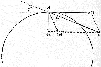
Fig. 196.
§ 195. Condition determining the Angle of the Vanes at the Inlet Surface of the Wheel.—The single condition necessary to be satisfied at the inlet surface of the wheel is that the water should enter the wheel without shock. This condition is satisfied if the direction of relative motion of the water and wheel is parallel to the first element of the wheel vanes.
Let A (fig. 196) be a point on the inlet surface of the wheel, and let vi represent in magnitude and direction the velocity of the water entering the wheel, and Vi the velocity of the wheel. Completing the parallelogram, vri is the direction of relative motion. Hence the angle between vri and Vi is the angle θ which the vanes should make with the inlet surface of the wheel.
§ 196. Example of the Method of designing a Turbine. Professor James Thomson’s Inward Flow Turbine.—
Let H = the available fall after deducting loss of head in pipes and channels from the gross fall; Q = the supply of water in cubic feet per second; and η = the efficiency of the turbine.
The work done per second is ηGQH, and the horse-power of the turbine is h.p. = ηGQH/550. If η is taken at 0.75, an allowance will be made for the frictional losses in the turbine, the leakage and the friction of the turbine shaft. Then h.p. = 0.085QH.
The velocity of flow through the turbine (uncorrected for the space occupied by the vanes and guide-blades) may be taken
ui = ui = 0.125 √2gH,
in which case about 1⁄64th of the energy of the fall is carried away by the water discharged.
The areas of the outlet and inlet surface of the wheel are then
2πrodo = 2πridi = Q / 0.125 √ (2gH).
If we take ro, so that the axial velocity of discharge from the central orifices of the wheel is equal to uo, we get
ro = 0.3984 √ (Q/√H), do = ro.
If, to obtain considerable steadying action of the centrifugal head, ri = 2ro, then di = 1⁄2do.
Speed of the Wheel.—Let Vi = 0.66 √2gH, or the speed due to half the fall nearly. Then the number of rotations of the turbine per second is
N = Vi / 2πri = 1.0579 √ (H √ H/Q);
also
Vo = Viro / ri = 0.33 √2gH.
Angle of Vanes with Outlet Surface.
Tan φ = uo / Vo = 0.125 / 0.33 = .3788;
φ = 21º nearly.
If this value is revised for the vane thickness it will ordinarily become about 25º.
Velocity with which the Water enters the Wheel.—The head producing the velocity is
H − (Vi2 / 2g) (1 + uo2 / Vi2) + ui2 / 2g = H {1 − .4356 (1 + 0.0358) + .0156} = 0.5646H.
Then the velocity is
Vi = .96 √2g (.5646H) = 0.721 √2gH.
Angle of Guide-Blades.
Sin γ = ui / vi = 0.125 / 0.721 = 0.173;
γ = 10° nearly.
Tangential Velocity of Water entering Wheel.
wi = vi cos γ = 0.7101 √2gH.
Angle of Vanes at Inlet Surface.
Cot θ = (wi − Vi) / ui = (.7101 − .66) / .125 = .4008;
θ = 68° nearly.
Hydraulic Efficiency of Wheel.
η = wiVi / gH = .7101 × .66 × 2 = 0.9373.
This, however, neglects the friction of wheel covers and leakage. The efficiency from experiment has been found to be 0.75 to 0.80.
Impulse and Partial Admission Turbines.
§ 197. The principal defect of most turbines with complete admission is the imperfection of the arrangements for working with less than the normal supply. With many forms of reaction turbine the efficiency is considerably reduced when the regulating sluices are partially closed, but it is exactly when the supply of water is deficient that it is most important to get out of it the greatest possible amount of work. The imperfection of the regulating arrangements is therefore, from the practical point of view, a serious defect. All turbine makers have sought by various methods to improve the regulating mechanism. B. Fourneyron, by dividing his wheel by horizontal diaphragms, virtually obtained three or more separate radial flow turbines, which could be successively set in action at their full power, but the arrangement is not altogether successful, because of the spreading of the water in the space between the wheel and guide-blades. Fontaine similarly employed two concentric axial flow turbines formed in the same casing. One was worked at full power, the other regulated. By this arrangement the loss of efficiency due to the action of the regulating sluice affected only half the water power. Many makers have adopted the expedient of erecting two or three separate turbines on the same waterfall. Then one or more could be put out of action and the others worked at full power. All these methods are rather palliatives than remedies. The movable guide-blades of Professor James Thomson meet the difficulty directly, but they are not applicable to every form of turbine.
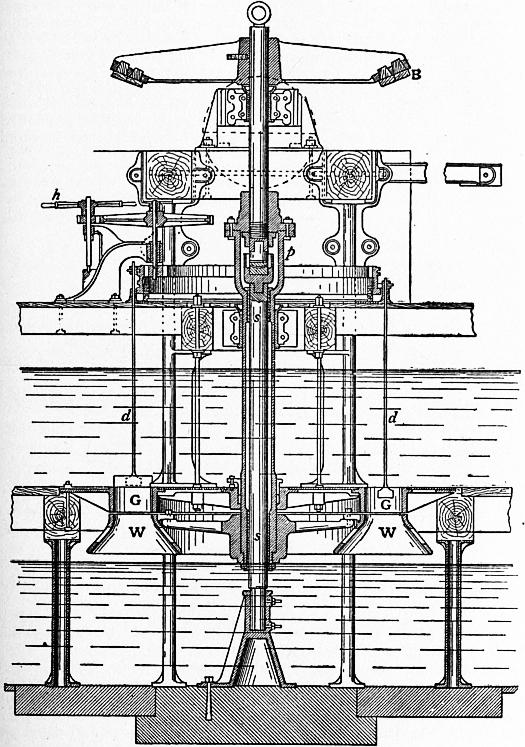
Fig. 197.
C. Callon, in 1840, patented an arrangement of sluices for axial or outward flow turbines, which were to be closed successively as the water supply diminished. By preference the sluices were closed by pairs, two diametrically opposite sluices forming a pair. The water was thus admitted to opposite but equal arcs of the wheel, and the forces driving the turbine were symmetrically placed. As soon as this arrangement was adopted, a modification of the mode of action of the water in the turbine became necessary. If the turbine wheel passages remain full of water during the whole rotation, the water contained in each passage must be put into motion each time it passes an open portion of the sluice, and stopped each time it passes a closed portion of the sluice. It is thus put into motion and stopped twice in each rotation. This gives rise to violent eddying motions and great loss of energy in shock. To prevent this, the turbine wheel with partial admission must be placed above the tail water, and the wheel passages be allowed to clear themselves of water, while passing from one open portion of the sluices to the next.
But if the wheel passages are free of water when they arrive at the open guide passages, then there can be no pressure other than atmospheric pressure in the clearance space between guides and wheel. The water must issue from the sluices with the whole velocity due to the head; received on the curved vanes of the wheel, the jets must be gradually deviated and discharged with a small final velocity only, precisely in the same way as when a single jet strikes a curved vane in the free air. Turbines of this kind are therefore termed turbines of free deviation. There is no variation of pressure in the jet during the whole time of its action on the wheel, and the whole energy of the jet is imparted to the wheel, simply by the impulse due to its gradual change of momentum. It is clear that the water may be admitted in exactly the same way to any fraction of the circumference at pleasure, without altering the efficiency of the wheel. The diameter of the wheel may be made as large as convenient, and the water admitted to a small fraction of the circumference only. Then the number of revolutions is independent of the water velocity, and may be kept down to a manageable value.
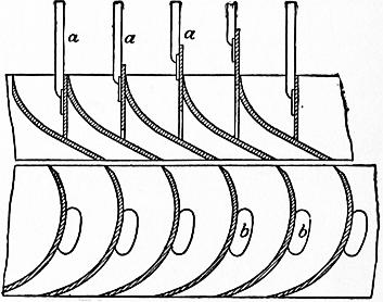
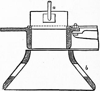
Fig. 198. Fig. 199.
§ 198. General Description of an Impulse Turbine or Turbine with Free Deviation.—Fig. 197 shows a general sectional elevation of a Girard turbine, in which the flow is axial. The water, admitted above a horizontal floor, passes down through the annular wheel containing the guide-blades G, G, and thence into the revolving wheel WW. The revolving wheel is fixed to a hollow shaft suspended from the pivot p. The solid internal shaft ss is merely a fixed column supporting the pivot. The advantage of this is that the pivot is accessible for lubrication and adjustment. B is the mortise bevel wheel by which the power of the turbine is given off. The sluices are worked by the hand wheel h, which raises them successively, in a way to be described presently. d, d are the sluice rods. Figs. 198, 199 show the sectional form of the guide-blade chamber and wheel and the curves of the wheel vanes and guide-blades, when drawn on a plane development of the cylindrical section of the wheel; a, a, a are the sluices for cutting off the water; b, b, b are apertures by which the entrance or exit of air is facilitated as the buckets empty and fill. Figs. 200, 201 show the guide-blade gear. a, a, a are the sluice rods as before. At the top of each sluice rod is a small block c, having a projecting tongue, which slides in the groove of the circular cam plate d, d. This circular plate is supported on the frame e, and revolves on it by means of the flanged rollers f. Inside, at the top, the cam plate is toothed, and gears into a spur pinion connected with the hand wheel h. At gg is an inclined groove or shunt. When the tongues of the blocks c, c arrive at g, they slide up to a second groove, or the reverse, according as the cam plate is revolved in one direction or in the other. As this operation takes place with each sluice successively, any number of sluices can be opened or closed as desired. The turbine is of 48 horse power on 5.12 ft. fall, and the supply of water varies from 35 to 112 cub. ft. per second. The efficiency in normal working is given as 73%. The mean diameter of the wheel is 6 ft., and the speed 27.4 revolutions per minute.
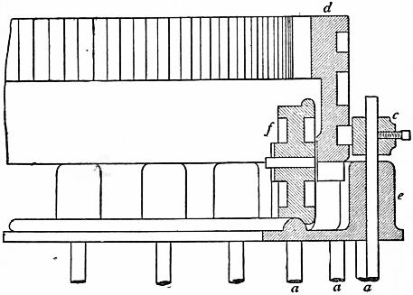
Fig. 200.
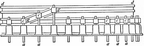
Fig. 201.
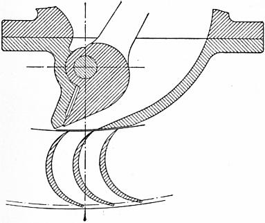
Fig. 202.
As an example of a partial admission radial flow impulse turbine, a 100 h.p. turbine at Immenstadt may be taken. The fall varies from 538 to 570 ft. The external diameter of the wheel is 41⁄2 ft., and its internal diameter 3 ft. 10 in. Normal speed 400 revs. per minute. Water is discharged into the wheel by a single nozzle, shown in fig. 202 with its regulating apparatus and some of the vanes. The water enters the wheel at an angle of 22° with the direction of motion, and the final angle of the wheel vanes is 20°. The efficiency on trial was from 75 to 78%.
§ 199. Theory of the Impulse Turbine.—The theory of the impulse turbine does not essentially differ from that of the reaction turbine, except that there is no pressure in the wheel opposing the discharge from the guide-blades. Hence the velocity with which the water enters the wheel is simply
vi = 0.96 √2g (H − ɧ),
where ɧ is the height of the top of the wheel above the tail water. If the hydropneumatic system is used, then ɧ = 0. Let Qm be the maximum supply of water, r1, r2 the internal and external radii of the wheel at the inlet surface; then
ui = Qm / {π(r22 − r12)}.
The value of ui may be about 0.45 √2g (H − ɧ), whence r1, r2 can be determined.
The guide-blade angle is then given by the equation
sin γ = ui / vi = 0.45 / 0.94 = .48;
γ = 29°.
The value of ui should, however, be corrected for the space occupied by the guide-blades.
The tangential velocity of the entering water is
wi = vi cos γ = 0.82 √2g (H − ɧ).
The circumferential velocity of the wheel may be (at mean radius)
Vi = 0.5 √2g (H − ɧ).
Hence the vane angle at inlet surface is given by the equation
cot θ = (wi − Vi) / ui = (0.82 − 0.5) / 0.45 = .71;
θ = 55°.
The relative velocity of the water striking the vane at the inlet edge is vri = ui cosec θ = 1.22ui. This relative velocity remains unchanged during the passage of the water over the vane; consequently the relative velocity at the point of discharge is vro = 1.22ui. Also in an axial flow turbine Vo = Vi.
If the final velocity of the water is axial, then
cos φ = Vo / vro = Vi / vri = 0.5 / (1.22 × 0.45) = cos 24º 23′.
This should be corrected for the vane thickness. Neglecting this, uo = vro sin φ = vri sin φ = ui cosec θ sin φ = 0.5ui. The discharging area of the wheel must therefore be greater than the inlet area in the ratio of at least 2 to 1. In some actual turbines the ratio is 7 to 3. This greater outlet area is obtained by splaying the wheel, as shown in the section (fig. 199).
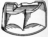
Fig. 203.
§ 200. Pelton Wheel.—In the mining district of California about 1860 simple impulse wheels were used, termed hurdy-gurdy wheels. The wheels rotated in a vertical plane, being supported on a horizontal axis. Round the circumference were fixed flat vanes which were struck normally by a jet from a nozzle of size varying with the head and quantity of water. Such wheels have in fact long been used. They are not efficient, but they are very simply constructed. Then attempts were made to improve the efficiency, first by using hemispherical cup vanes, and then by using a double cup vane with a central dividing ridge, an arrangement invented by Pelton. In this last form the water from the nozzle passes half to each side of the wheel, just escaping clear of the backs of the advancing buckets. Fig. 203 shows a Pelton vane. Some small modifications have been made by other makers, but they are not of any great importance. Fig. 204 shows a complete Pelton wheel with frame and casing, supply pipe and nozzle. Pelton wheels have been very largely used in America and to some extent in Europe. They are extremely simple and easy to construct or repair and on falls of 100 ft. or more are very efficient. The jet strikes tangentially to the mean radius of the buckets, and the face of the buckets is not quite radial but at right angles to the direction of the jet at the point of first impact. For greatest efficiency the peripheral velocity of the wheel at the mean radius of the buckets should be a little less than half the velocity of the jet. As the radius of the wheel can be taken arbitrarily, the number of revolutions per minute can be accommodated to that of the machinery to be driven. Pelton wheels have been made as small as 4 in. diameter, for driving sewing machines, and as large as 24 ft. The efficiency on high falls is about 80%. When large power is required two or three nozzles are used delivering on one wheel. The width of the buckets should be not less than seven times the diameter of the jet.
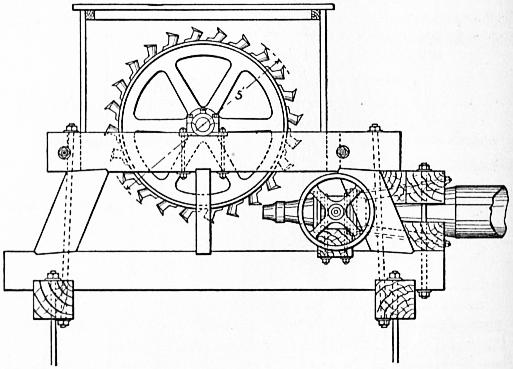
Fig. 204.
At the Comstock mines, Nevada, there is a 36-in. Pelton wheel made of a solid steel disk with phosphor bronze buckets riveted to the rim. The head is 2100 ft. and the wheel makes 1150 revolutions per minute, the peripheral velocity being 180 ft. per sec. With a 1⁄2-in. nozzle the wheel uses 32 cub. ft. of water per minute and develops 100 h.p. At the Chollarshaft, Nevada, there are six Pelton wheels on a fall of 1680 ft. driving electrical generators. With 5⁄8-in. nozzles each develops 125 h.p.
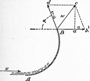
Fig. 205
§ 201. Theory of the Pelton Wheel.—Suppose a jet with a velocity v strikes tangentially a curved vane AB (fig. 205) moving in the same direction with the velocity u. The water will flow over the vane with the relative velocity v − u and at B will have the tangential relative velocity v − u making an angle α with the direction of the vane’s motion. Combining this with the velocity u of the vane, the absolute velocity of the water leaving the vane will be w = Bc. The component of w in the direction of motion of the vane is Ba = Bb − ab = u − (v − u) cos α. Hence if Q is the quantity of water reaching the vane per second the change of momentum per second in the direction of the vane’s motion is (GQ/g) [v − {u − (v − u) cos α}] = (GQ/g) (v − u) (1 + cos α). If a = 0°, cos α = 1, and the change of momentum per second, which is equal to the effort driving the vane, is P = 2(GQ/g) (v − u). The work done on the vane is Pu = 2(GQ/g) (v − u)u. If a series of vanes are interposed in succession, the quantity of water impinging on the vanes per second is the total discharge of the nozzle, and the energy expended at the nozzle is GQv2/2g. Hence the efficiency of the arrangement is, when α = 0°, neglecting friction,
η = 2Pu / GQv2 = 4 (v − u) u/v2,
which is a maximum and equal to unity if u = 1⁄2v. In that case the whole energy of the jet is usefully expended in driving the series of vanes. In practice α cannot be quite zero or the water leaving one vane would strike the back of the next advancing vane. Fig. 203 shows a Pelton vane. The water divides each way, and leaves the vane on each side in a direction nearly parallel to the direction of motion of the vane. The best velocity of the vane is very approximately half the velocity of the jet.
§ 202. Regulation of the Pelton Wheel.—At first Pelton wheels were adjusted to varying loads merely by throttling the supply. This method involves a total loss of part of the head at the sluice or throttle valve. In addition as the working head is reduced, the relation between wheel velocity and jet velocity is no longer that of greatest efficiency. Next a plan was adopted of deflecting the jet so that only part of the water reached the wheel when the load was reduced, the rest going to waste. This involved the use of an equal quantity of water for large and small loads, but it had, what in some cases is an advantage, the effect of preventing any water hammer in the supply pipe due to the action of the regulator. In most cases now regulation is effected by varying the section of the jet. A conical needle in the nozzle can be advanced or withdrawn so as to occupy more or less of the aperture of the nozzle. Such a needle can be controlled by an ordinary governor.
§ 203. General Considerations on the Choice of a Type of Turbine.—The circumferential speed of any turbine is necessarily a fraction of the initial velocity of the water, and therefore is greater as the head is greater. In reaction turbines with complete admission the number of revolutions per minute becomes inconveniently great, for the diameter cannot be increased beyond certain limits without greatly reducing the efficiency. In impulse turbines with partial admission the diameter can be chosen arbitrarily and the number of revolutions kept down on high falls to any desired amount. Hence broadly reaction turbines are better and less costly on low falls, and impulse turbines on high falls. For variable water flow impulse turbines have some advantage, being more efficiently regulated. On the other hand, impulse turbines lose efficiency seriously if their speed varies from the normal speed due to the head. If the head is very variable, as it often is on low falls, and the turbine must run at the same speed whatever the head, the impulse turbine is not suitable. Reaction turbines can be constructed so as to overcome this difficulty to a great extent. Axial flow turbines with vertical shafts have the disadvantage that in addition to the weight of the turbine there is an unbalanced water pressure to be carried by the footstep or collar bearing. In radial flow turbines the hydraulic pressures are balanced. The application of turbines to drive dynamos directly has involved some new conditions. The electrical engineer generally desires a high speed of rotation, and a very constant speed at all times. The reaction turbine is generally more suitable than the impulse turbine. As the diameter of the turbine depends on the quantity of water and cannot be much varied without great inefficiency, a difficulty arises on low falls. This has been met by constructing four independent reaction turbines on the same shaft, each having of course the diameter suitable for one-quarter of the whole discharge, and having a higher speed of rotation than a larger turbine. The turbines at Rheinfelden and Chevres are so constructed. To ensure constant speed of rotation when the head varies considerably without serious inefficiency, an axial flow turbine is generally used. It is constructed of three or four concentric rings of vanes, with independent regulating sluices, forming practically independent turbines of different radii. Any one of these or any combination can be used according to the state of the water. With a high fall the turbine of largest radius only is used, and the speed of rotation is less than with a turbine of smaller radius. On the other hand, as the fall decreases the inner turbines are used either singly or together, according to the power required. At the Zürich waterworks there are turbines of 90 h.p. on a fall varying from 101⁄2 ft. to 43⁄4 ft. The power and speed are kept constant. Each turbine has three concentric rings. The outermost ring gives 90 h.p. with 105 cub. ft. per second and the maximum fall. The outer and middle compartments give the same power with 140 cub. ft. per second and a fall of 7 ft. 10 in. All three compartments working together develop the power with about 250 cub. ft. per second. In some tests the efficiency was 74% with the outer ring working alone, 75.4% with the outer and middle ring working and a fall of 7 ft., and 80.7% with all the rings working.
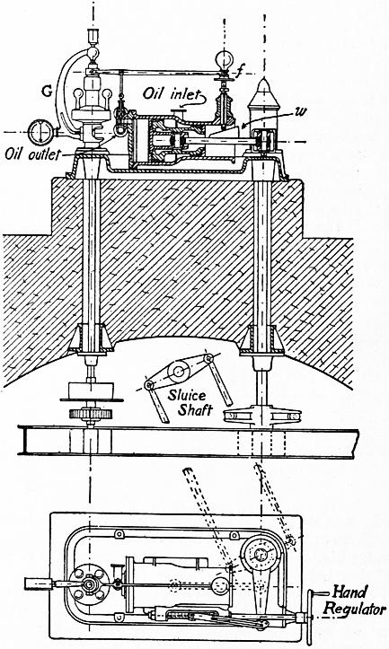
Fig. 206.
§ 204. Speed Governing.—When turbines are used to drive dynamos direct, the question of speed regulation is of great importance. Steam engines using a light elastic fluid can be easily regulated by governors acting on throttle or expansion valves. It is different with water turbines using a fluid of great inertia. In one of the Niagara penstocks there are 400 tons of water flowing at 10 ft. per second, opposing enormous resistance to rapid change of speed of flow. The sluices of water turbines also are necessarily large and heavy. Hence relay governors must be used, and the tendency of relay governors to hunt must be overcome. In the Niagara Falls Power House No. 1, each turbine has a very sensitive centrifugal governor acting on a ratchet relay. The governor puts into gear one or other of two ratchets driven by the turbine itself. According as one or the other ratchet is in gear the sluices are raised or lowered. By a subsidiary arrangement the ratchets are gradually put out of gear unless the governor puts them in gear again, and this prevents the over correction of the speed from the lag in the action of the governor. In the Niagara Power House No. 2, the relay is an hydraulic relay similar in principle, but rather more complicated in arrangement, to that shown in fig. 206, which is a governor used for the 1250 h.p. turbines at Lyons. The sensitive governor G opens a valve and puts into action a plunger driven by oil pressure from an oil reservoir. As the plunger moves forward it gradually closes the oil admission valve by lowering the fulcrum end f of the valve lever which rests on a wedge w attached to the plunger. If the speed is still too high, the governor reopens the valve. In the case of the Niagara turbines the oil pressure is 1200 ℔ per sq. in. One millimetre of movement of the governor sleeve completely opens the relay valve, and the relay plunger exerts a force of 50 tons. The sluices can be completely opened or shut in twelve seconds. The ordinary variation of speed of the turbine with varying load does not exceed 1%. If all the load is thrown off, the momentary variation of speed is not more than 5%. To prevent hydraulic shock in the supply pipes, a relief valve is provided which opens if the pressure is in excess of that due to the head.
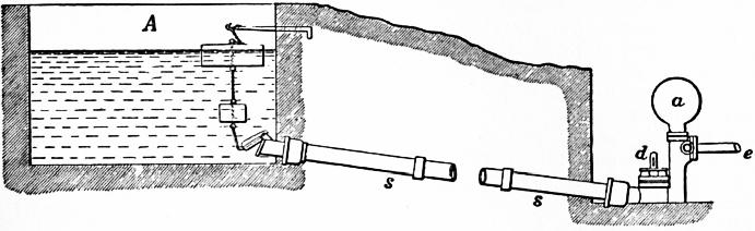
Fig. 207.
§ 205. The Hydraulic Ram.—The hydraulic ram is an arrangement by which a quantity of water falling a distance h forces a portion of the water to rise to a height h1, greater than h. It consists of a supply reservoir (A, fig. 207), into which the water enters from some natural stream. A pipe s of considerable length conducts the water to a lower level, where it is discharged intermittently through a self-acting pulsating valve at d. The supply pipe s may be fitted with a flap valve for stopping the ram, and this is attached in some cases to a float, so that the ram starts and stops itself automatically, according as the supply cistern fills or empties. The lower float is just sufficient to keep open the flap after it has been raised by the action of the upper float. The length of chain is adjusted so that the upper float opens the flap when the level in the cistern is at the desired height. If the water-level falls below the lower float the flap closes. The pipe s should be as long and as straight as possible, and as it is subjected to considerable pressure from the sudden arrest of the motion of the water, it must be strong and strongly jointed. a is an air vessel, and e the delivery pipe leading to the reservoir at a higher level than A, into which water is to be pumped. Fig. 208 shows in section the construction of the ram itself. d is the pulsating discharge valve already mentioned, which opens inwards and downwards. The stroke of the valve is regulated by the cotter through the spindle, under which are washers by which the amount of fall can be regulated. At o is a delivery valve, opening outwards, which is often a ball-valve but sometimes a flap-valve. The water which is pumped passes through this valve into the air vessel a, from which it flows by the delivery pipe in a regular stream into the cistern to which the water is to be raised. In the vertical chamber behind the outer valve a small air vessel is formed, and into this opens an aperture 1⁄4 in. in diameter, made in a brass screw plug b. The hole is reduced to 1⁄16 in. in diameter at the outer end of the plug and is closed by a small valve opening inwards. Through this, during the rebound after each stroke of the ram, a small quantity of air is sucked in which keeps the air vessel supplied with its elastic cushion of air.