VOLUME XIV SLICE I Husband to Hydrolysis (continued 10)
Reading edition
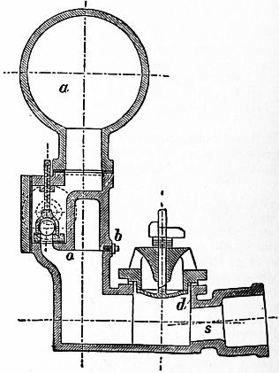
Fig. 208.
During the recoil after a sudden closing of the valve d, the pressure below it is diminished and the valve opens, permitting outflow. In consequence of the flow through this valve, the water in the supply pipe acquires a gradually increasing velocity. The upward flow of the water, towards the valve d, increases the pressure tending to lift the valve, and at last, if the valve is not too heavy, lifts and closes it. The forward momentum of the column in the supply pipe being destroyed by the stoppage of the flow, the water exerts a pressure at the end of the pipe sufficient to open the delivery valve o, and to cause a portion of the water to flow into the air vessel. As the water in the supply pipe comes to rest and recoils, the valve d opens again and the operation is repeated. Part of the energy of the descending column is employed in compressing the air at the end of the supply pipe and expanding the pipe itself. This causes a recoil of the water which momentarily diminishes the pressure in the pipe below the pressure due to the statical head. This assists in opening the valve d. The recoil of the water is sufficiently great to enable a pump to be attached to the ram body instead of the direct rising pipe. With this arrangement a ram working with muddy water may be employed to raise clear spring water. Instead of lifting the delivery valve as in the ordinary ram, the momentum of the column drives a sliding or elastic piston, and the recoil brings it back. This piston lifts and forces alternately the clear water through ordinary pump valves.
Pumps
§ 206. The different classes of pumps correspond almost exactly to the different classes of water motors, although the mechanical details of the construction are somewhat different. They are properly reversed water motors. Ordinary reciprocating pumps correspond to water-pressure engines. Chain and bucket pumps are in principle similar to water wheels in which the water acts by weight. Scoop wheels are similar to undershot water wheels, and centrifugal pumps to turbines.
Reciprocating Pumps are single or double acting, and differ from water-pressure engines in that the valves are moved by the water instead of by automatic machinery. They may be classed thus:—
1. Lift Pumps.—The water drawn through a foot valve on the ascent of the pump bucket is forced through the bucket valve when it descends, and lifted by the bucket when it reascends. Such pumps give an intermittent discharge.
2. Plunger or Force Pumps, in which the water drawn through the foot valve is displaced by the descent of a solid plunger, and forced through a delivery valve. They have the advantage that the friction is less than that of lift pumps, and the packing round the plunger is easily accessible, whilst that round a lift pump bucket is not. The flow is intermittent.
3. The Double-acting Force Pump is in principle a double plunger pump. The discharge fluctuates from zero to a maximum and back to zero each stroke, but is not arrested for any appreciable time.
4. Bucket and Plunger Pumps consist of a lift pump bucket combined with a plunger of half its area. The flow varies as in a double-acting pump.
5. Diaphragm Pumps have been used, in which the solid plunger is replaced by an elastic diaphragm, alternately depressed into and raised out of a cylinder.
As single-acting pumps give an intermittent discharge three are generally used on cranks at 120°. But with all pumps the variation of velocity of discharge would cause great waste of work in the delivery pipes when they are long, and even danger from the hydraulic ramming action of the long column of water. An air vessel is interposed between the pump and the delivery pipes, of a volume from 5 to 100 times the space described by the plunger per stroke. The air in this must be replenished from time to time, or continuously, by a special air-pump. At low speeds not exceeding 30 ft. per minute the delivery of a pump is about 90 to 95% of the volume described by the plunger or bucket, from 5 to 10% of the discharge being lost by leakage. At high speeds the quantity pumped occasionally exceeds the volume described by the plunger, the momentum of the water keeping the valves open after the turn of the stroke.
The velocity of large mining pumps is about 140 ft. per minute, the indoor or suction stroke being sometimes made at 250 ft. per minute. Rotative pumping engines of large size have a plunger speed of 90 ft. per minute. Small rotative pumps are run faster, but at some loss of efficiency. Fire-engine pumps have a speed of 180 to 220 ft. per minute.
The efficiency of reciprocating pumps varies very greatly. Small reciprocating pumps, with metal valves on lifts of 15 ft., were found by Morin to have an efficiency of 16 to 40%, or on the average 25%. When used to pump water at considerable pressure, through hose pipes, the efficiency rose to from 28 to 57%, or on the average, with 50 to 100 ft. of lift, about 50%. A large pump with barrels 18 in. diameter, at speeds under 60 ft. per minute, gave the following results:—
Lift in feet 141⁄2 34 47
Efficiency .46 .66 .70
The very large steam-pumps employed for waterworks, with 150 ft. or more of lift, appear to reach an efficiency of 90%, not including the friction of the discharge pipes. Reckoned on the indicated work of the steam-engine the efficiency may be 80%.
Many small pumps are now driven electrically and are usually three-throw single-acting pumps driven from the electric motor by gearing. It is not convenient to vary the speed of the motor to accommodate it to the varying rate of pumping usually required. Messrs Hayward Tyler have introduced a mechanism for varying the stroke of the pumps (Sinclair’s patent) from full stroke to nil, without stopping the pumps.
§ 207. Centrifugal Pump.—For large volumes of water on lifts not exceeding about 60 ft. the most convenient pump is the centrifugal pump. Recent improvements have made it available also for very high lifts. It consists of a wheel or fan with curved vanes enclosed in an annular chamber. Water flows in at the centre and is discharged at the periphery. The fan may rotate in a vertical or horizontal plane and the water may enter on one or both sides of the fan. In the latter case there is no axial unbalanced pressure. The fan and its casing must be filled with water before it can start, so that if not drowned there must be a foot valve on the suction pipe. When no special attention needs to be paid to efficiency the water may have a velocity of 6 to 7 ft. in the suction and delivery pipes. The fan often has 6 to 12 vanes. For a double-inlet fan of diameter D, the diameter of the inlets is D/2. If Q is the discharge in cub. ft. per second D = about 0.6 √Q in average cases. The peripheral speed is a little greater than the velocity due to the lift. Ordinary centrifugal pumps will have an efficiency of 40 to 60%.
The first pump of this kind which attracted notice was one exhibited by J. G. Appold in 1851, and the special features of his pump have been retained in the best pumps since constructed. Appold’s pump raised continuously a volume of water equal to 1400 times its own capacity per minute. It had no valves, and it permitted the passage of solid bodies, such as walnuts and oranges, without obstruction to its working. Its efficiency was also found to be good.
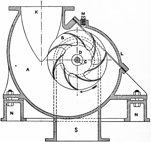
Fig. 209.
Fig. 209 shows the ordinary form of a centrifugal pump. The pump disk and vanes B are cast in one, usually of bronze,
and the disk is keyed on the driving shaft C. The casing A has a spirally enlarging discharge passage into the discharge pipe K. A cover L gives access to the pump. S is the suction pipe which opens into the pump disk on both sides at D.
Fig. 210 shows a centrifugal pump differing from ordinary centrifugal pumps in one feature only. The water rises through a suction pipe S, which divides so as to enter the pump wheel W at the centre on each side. The pump disk or wheel is very similar to a turbine wheel. It is keyed on a shaft driven by a belt on a fast and loose pulley arrangement at P. The water rotating in the pump disk presses outwards, and if the speed is sufficient a continuous flow is maintained through the pump and into the discharge pipe D. The special feature in this pump is that the water, discharged by the pump disk with a whirling velocity of not inconsiderable magnitude, is allowed to continue rotation in a chamber somewhat larger than the pump. The use of this whirlpool chamber was first suggested by Professor James Thomson. It utilizes the energy due to the whirling velocity of the water which in most pumps is wasted in eddies in the discharge pipe. In the pump shown guide-blades are also added which have the direction of the stream lines in a free vortex. They do not therefore interfere with the action of the water when pumping the normal quantity, but only prevent irregular motion. At A is a plug by which the pump case is filled before starting. If the pump is above the water to be pumped, a foot valve is required to permit the pump to be filled. Sometimes instead of the foot valve a delivery valve is used, an air-pump or steam jet pump being employed to exhaust the air from the pump case.
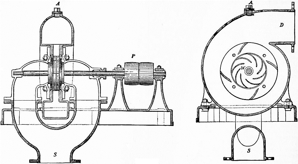
Fig. 210.
§ 208. Design and Proportions of a Centrifugal Pump.—The design of the pump disk is very simple. Let ri, ro be the radii of the inlet and outlet surfaces of the pump disk, di, do the clear axial width at those radii. The velocity of flow through the pump may be taken the same as for a turbine. If Q is the quantity pumped, and H the lift,
ui = 0.25 √2gH. 2πridi = Q / ui.
(1)
Also in practice
di = 1.2 ri ....
Hence,
ri = .2571 √ (Q / √H).
(2)
Usually
ro = 2ri,
and
do = di or 1⁄2 di
according as the disk is parallel-sided or coned. The water enters the wheel radially with the velocity ui, and
uo = Q / 2πrodo.
(3)
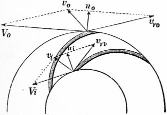
Fig. 211.
Fig. 211 shows the notation adopted for the velocities. Suppose the water enters the wheel with the velocity vi, while the velocity of the wheel is Vi. Completing the parallelogram, vri is the relative velocity of the water and wheel, and is the proper direction of the wheel vanes. Also, by resolving, ui and wi are the component velocities of flow and velocities of whir of the velocity vi of the water. At the outlet surface, vo is the final velocity of discharge, and the rest of the notation is similar to that for the inlet surface.
Usually the water flows equally in all directions in the eye of the wheel, in that case vi is radial. Then, in normal conditions of working, at the inlet surface,
vi = ui wi = 0 tan θ = ui / Vi vri = ui cosec θ = √ (ui2 + Vi2).
(4)
If the pump is raising less or more than its proper quantity, θ will not satisfy the last condition, and there is then some loss of head in shock.
At the outer circumference of the wheel or outlet surface,
vro = uo cosec φ wo = Vo − uo cot φ vo = √ {uo2 + (Vo − uo cot φ)2}
(5)
Variation of Pressure in the Pump Disk.—Precisely as in the case of turbines, it can be shown that the variation of pressure between the inlet and outlet surfaces of the pump is
ho − hi = (Vo2 − Vi2) / 2g − (vro2 − vri2) / 2g.
Inserting the values of vro, vri in (4) and (5), we get for normal conditions of working
ho − hi = (Vo2 − Vi2) / 2g − uo2 cosec2 φ / 2g + (ui2 + Vi2) / 2g = Vo2 / 2g − uo2 cosec2 φ / 2g + ui2 / 2g.
(6)
Hydraulic Efficiency of the Pump.—Neglecting disk friction, journal friction, and leakage, the efficiency of the pump can be found in the same way as that of turbines (§ 186). Let M be the moment of the couple rotating the pump, and α its angular velocity; wo, ro the tangential velocity of the water and radius at the outlet surface; wi, ri the same quantities at the inlet surface. Q being the discharge per second, the change of angular momentum per second is
(GQ/g) (woro − wiri).
Hence
M = (GQ/g) (woro − wiri).
In normal working, wi = 0. Also, multiplying by the angular velocity, the work done per second is
Mα = (GQ/g) woroα.
But the useful work done in pumping is GQH. Therefore the efficiency is
η = GQH / Mα = gH / woroα = gH / woVo.
(7)
§ 209. Case 1. Centrifugal Pump with no Whirlpool Chamber.—When no special provision is made to utilize the energy of motion of the water leaving the wheel, and the pump discharges directly into a chamber in which the water is flowing to the discharge pipe, nearly the whole of the energy of the water leaving the disk is wasted. The water leaves the disk with the more or less considerable velocity vo, and impinges on a mass flowing to the discharge pipe at the much slower velocity vs. The radial component of vo is almost necessarily wasted. From the tangential component there is a gain of pressure
(wo2 − vs2) / 2g − (wo − vs)2 / 2g = vs (wo − vs) / g,
which will be small, if vs is small compared with wo. Its greatest value, if vs = 1⁄2wo, is 1⁄2wo2/2g, which will always be a small part of the whole head. Suppose this neglected. The whole variation of pressure in the pump disk then balances the lift and the head ui2/2g necessary to give the initial velocity of flow in the eye of the wheel.
ui2 / 2g + H = Vo2 / 2g − uo2 cosec2 φ / 2g + ui2 / 2g,
H = Vo2 / 2g − uo2 cosec2 φ / 2g
or
Vo = √ (2gH + uo2 cosec2 φ).
(8)
and the efficiency of the pump is, from (7),
η = gH / Vowo = gH / {V (Vo − no cot φ) }, = (Vo2 − uo2 cosec2 φ) / {2Vo (Vo − uo cot φ) },
(9)
For φ = 90°,
η = (Vo2 − uo2) / 2Vo2,
which is necessarily less than 1⁄2. That is, half the work expended in driving the pump is wasted. By recurving the vanes, a plan introduced by Appold, the efficiency is increased, because the velocity vo of discharge from the pump is diminished. If φ is very small,
cosec φ = cot φ;
and then
η = (Vo, + uo cosec φ) / 2Vo,
which may approach the value 1, as φ tends towards 0. Equation (8) shows that uo cosec φ cannot be greater than Vo. Putting uo = 0.25 √(2gH) we get the following numerical values of the efficiency and the circumferential velocity of the pump:—
φ η Vo
90° 0.47 1.03 √2gH
45° 0.56 1.06 ”
30° 0.65 1.12 ”
20° 0.73 1.24 ”
10° 0.84 1.75 ”
φ cannot practically be made less than 20°; and, allowing for the frictional losses neglected, the efficiency of a pump in which φ = 20° is found to be about .60.
§ 210. Case 2. Pump with a Whirlpool Chamber, as in fig. 210.—Professor James Thomson first suggested that the energy of the water after leaving the pump disk might be utilized, if a space were left in which a free vortex could be formed. In such a free vortex the velocity varies inversely as the radius. The gain of pressure in the vortex chamber is, putting ro, rw for the radii to the outlet surface of wheel and to outside of free vortex,
vo2 ( 1 − ro2 ) = vo2 ( 1 − k2 ),
2g rw2 2g
if
k = ro / rw.
The lift is then, adding this to the lift in the last case,
H = {Vo2 − uo2 cosec2 φ + vo2 (1 − k2)} / 2g.
But
vo2 = Vo2 − 2Vouo cot φ + uo2 cosec2 φ;
∴ H = {(2 − k2) Vo2 − 2kVouo cot φ − k2uo2 cosec2 φ} / 2g.
(10)
Putting this in the expression for the efficiency, we find a considerable increase of efficiency. Thus with
φ = 90° and k = 1⁄2, η = 7⁄8 nearly,
φ a small angle and k = 1⁄2, η = 1 nearly.
With this arrangement of pump, therefore, the angle at the outer ends of the vanes is of comparatively little importance. A moderate angle of 30° or 40° may very well be adopted. The following numerical values of the velocity of the circumference of the pump have been obtained by taking k = 1⁄2, and uo = 0.25√(2gH).
φ Vo
90° .762 √2gH
45° .842 ”
30° .911 ”
20° 1.023 ”
The quantity of water to be pumped by a centrifugal pump necessarily varies, and an adjustment for different quantities of water cannot easily be introduced. Hence it is that the average efficiency of pumps of this kind is in practice less than the efficiencies given above. The advantage of a vortex chamber is also generally neglected. The velocity in the supply and discharge pipes is also often made greater than is consistent with a high degree of efficiency. Velocities of 6 or 7 ft. per second in the discharge and suction pipes, when the lift is small, cause a very sensible waste of energy; 3 to 6 ft. would be much better. Centrifugal pumps of very large size have been constructed. Easton and Anderson made pumps for the North Sea canal in Holland to deliver each 670 tons of water per minute on a lift of 5 ft. The pump disks are 8 ft. diameter. J. and H. Gwynne constructed some pumps for draining the Ferrarese Marshes, which together deliver 2000 tons per minute. A pump made under Professor J. Thomson’s direction for drainage works in Barbados had a pump disk 16 ft. in diameter and a whirlpool chamber 32 ft. in diameter. The efficiency of centrifugal pumps when delivering less or more than the normal quantity of water is discussed in a paper in the Proc. Inst. Civ. Eng. vol. 53.
§ 211. High Lift Centrifugal Pumps.—It has long been known that centrifugal pumps could be worked in series, each pump overcoming a part of the lift. This method has been perfected, and centrifugal pumps for very high lifts with great efficiency have been used by Sulzer and others. C. W. Darley (Proc. Inst. Civ. Eng., supplement to vol. 154, p. 156) has described some pumps of this new type driven by Parsons steam turbines for the water supply of Sydney, N.S.W. Each pump was designed to deliver 11⁄2 million gallons per twenty-four hours against a head of 240 ft. at 3300 revs. per minute. Three pumps in series give therefore a lift of 720 ft. The pump consists of a central double-sided impeller 12 in. diameter. The water entering at the bottom divides and enters the runner at each side through a bell-mouthed passage. The shaft is provided with ring and groove glands which on the suction side keep the air out and on the pressure side prevent leakage. Some water from the pressure side leaks through the glands, but beyond the first grooves it passes into a pocket and is returned to the suction side of the pump. For the glands on the suction side water is supplied from a low-pressure service. No packing is used in the glands. During the trials no water was seen at the glands. The following are the results of tests made at Newcastle:—
I. II. III. IV.
Duration of test hours 2 1.54 1.2 1.55
Steam pressure ℔ per sq. in. 57 57 84 55
Weight of steam per water h.p. hour ℔ 27.93 30.67 28.83 27.89
Speed in revs, per min. 3300 3330 3710 3340
Height of suction ft. 11 11 11 11
Total lift ft. 762 744 917 756
Million galls. per day pumped—
By Ventun meter 1.573 1.499 1.689 1.503
By orifice 1.623 1.513 1.723 1.555
Water h.p. 252 235 326 239
In trial IV. the steam was superheated 95° F. From other trials under the same conditions as trial I. the Parsons turbine uses 15.6 ℔ of steam per brake h.p. hour, so that the combined efficiency of turbine and pumps is about 56%, a remarkably good result.
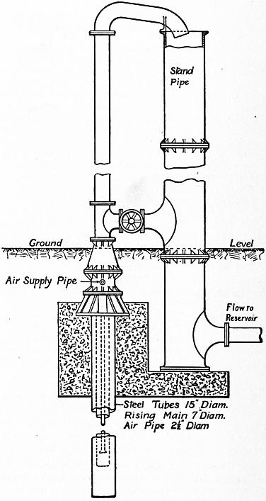
Fig. 212.
§ 212. Air-Lift Pumps.—An interesting and simple method of pumping by compressed air, invented by Dr J. Pohlé of Arizona, is likely to be very useful in certain cases. Suppose a rising main placed in a deep bore hole in which there is a considerable depth of water. Air compressed to a sufficient pressure is conveyed by an air pipe and introduced at the lower end of the rising main. The air rising In the main diminishes the average density of the contents of the main, and their aggregate weight no longer balances the pressure at the lower end of the main due to its submersion. An upward flow is set up, and if the air supply is sufficient the water in the rising main is lifted to any required height. The higher the lift above the level in the bore hole the deeper must be the point at which air is injected. Fig. 212 shows an airlift pump constructed for W. H. Maxwell at the Tunbridge Wells waterworks. There is a two-stage steam air compressor, compressing air to from 90 to 100 ℔ per sq. in. The bore hole is 350 ft. deep, lined with steel pipes 15 in. diameter for 200 ft. and with perforated pipes 131⁄2 in. diameter for the lower 150 ft. The rest level of the water is 96 ft. from the ground-level, and the level when pumping 32,000 gallons per hour is 120 ft. from the ground-level. The rising main is 7 in. diameter, and is carried nearly to the bottom of the bore hole and to 20 ft. above the ground-level. The air pipe is 21⁄2 in. diameter. In a trial run 31,402 gallons per hour were raised 133 ft. above the level in the well. Trials of the efficiency of the system made at San Francisco with varying conditions will be found in a paper by E. A. Rix (Journ. Amer. Assoc. Eng. Soc. vol. 25, 1900). Maxwell found the best results when the ratio of immersion to lift was 3 to 1 at the start and 2.2 to 1 at the end of the trial. In these conditions the efficiency was 37% calculated on the indicated h.p. of the steam-engine, and 46% calculated on the indicated work of the compressor. 2.7 volumes of free air were used to 1 of water lifted. The system is suitable for temporary purposes, especially as the quantity of water raised is much greater than could be pumped by any other system in a bore hole of a given size. It is useful for clearing a boring of sand and may be advantageously used permanently when a boring is in sand or gravel which cannot be kept out of the bore hole. The initial cost is small.
§ 213. Centrifugal Fans.—Centrifugal fans are constructed similarly to centrifugal pumps, and are used for compressing air to pressures not exceeding 10 to 15 in. of water-column. With this small variation of pressure the variation of volume and density of the air may be neglected without sensible error. The conditions of pressure and discharge for fans are generally less accurately known than in the case of pumps, and the design of fans is generally somewhat crude. They seldom have whirlpool chambers, though a large expanding outlet is provided in the case of the important Guibal fans used in mine ventilation.
It is usual to reckon the difference of pressure at the inlet and outlet of a fan in inches of water-column. One inch of water-column = 64.4 ft. of air at average atmospheric pressure = 5.2℔ per sq. ft.
Roughly the pressure-head produced in a fan without means of utilizing the kinetic energy of discharge would be v2/2g ft. of air, or 0.00024 v2 in. of water, where v is the velocity of the tips of the fan blades in feet per second. If d is the diameter of the fan and t the width at the external circumference, then πdt is the discharge area of the fan disk. If Q is the discharge in cub. ft. per sec., u = Q/π dt is the radial velocity of discharge which is numerically equal to the discharge per square foot of outlet in cubic feet per second. As both the losses in the fan and the work done are roughly proportional to u2 in fans of the same type, and are also proportional to the gauge pressure p, then if the losses are to be a constant percentage of the work done u may be taken proportional to √p. In ordinary cases u = about 22 √p. The width t of the fan is generally from 0.35 to 0.45d. Hence if Q is given, the diameter of the fan should be:—
For t = 0.35d, d = 0.20 √ (Q / √p) For t = 0.45d, d = 0.18 √ (Q / √p)
If p is the pressure difference in the fan in inches of water, and N the revolutions of fan,
v = πdN/60 ft. per sec.
N = 1230 √ p/d revs. per min.
As the pressure difference is small, the work done in compressing the air is almost exactly 5.2pQ foot-pounds per second. Usually, however, the kinetic energy of the air in the discharge pipe is not inconsiderable compared with the work done in compression. If w is the velocity of the air where the discharge pressure is measured, the air carries away w2/2g foot-pounds per ℔ of air as kinetic energy. In Q cubic feet or 0.0807Q ℔ the kinetic energy is 0.00125 Qw2 foot-pounds per second.
The efficiency of fans is reckoned in two ways. If B.H.P. is the effective horse-power applied at the fan shaft, then the efficiency reckoned on the work of compression is
η = 5.2pQ / 550 B.H.P.
On the other hand, if the kinetic energy in the delivery pipe is taken as part of the useful work the efficiency is
η2 = (5.2 pQ + 0.00125 Qw2) / 550 B.H.P.
Although the theory above is a rough one it agrees sufficiently with experiment, with some merely numerical modifications.
An extremely interesting experimental investigation of the action of centrifugal fans has been made by H. Heenan and W. Gilbert (Proc. Inst. Civ. Eng. vol. 123, p. 272). The fans delivered through an air trunk in which different resistances could be obtained by introducing diaphragms with circular apertures of different sizes. Suppose a fan run at constant speed with different resistances and the compression pressure, discharge and brake horse-power measured. The results plot in such a diagram as is shown in fig. 213. The less the resistance to discharge, that is the larger the opening in the air trunk, the greater the quantity of air discharged at the given speed of the fan. On the other hand the compression pressure diminishes. The curve marked total gauge is the compression pressure + the velocity head in the discharge pipe, both in inches of water. This curve falls, but not nearly so much as the compression curve, when the resistance in the air trunk is diminished. The brake horse-power increases as the resistance is diminished because the volume of discharge increases very much. The curve marked efficiency is the efficiency calculated on the work of compression only. It is zero for no discharge, and zero also when there is no resistance and all the energy given to the air is carried away as kinetic energy. There is a discharge for which this efficiency is a maximum; it is about half the discharge which there is when there is no resistance and the delivery pipe is full open. The conditions of speed and discharge corresponding to the greatest efficiency of compression are those ordinarily taken as the best normal conditions of working. The curve marked total efficiency gives the efficiency calculated on the work of compression and kinetic energy of discharge. Messrs Gilbert and Heenan found the efficiencies of ordinary fans calculated on the compression to be 40 to 60% when working at about normal conditions.
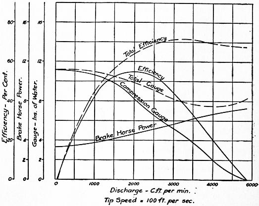
Fig. 213.
Taking some of Messrs Heenan and Gilbert’s results for ordinary fans in normal conditions, they have been found to agree fairly with the following approximate rules. Let pc be the compression pressure and q the volume discharged per second per square foot of outlet area of fan. Then the total gauge pressure due to pressure of compression and velocity of discharge is approximately: p = pc + 0.0004q2 in. of water, so that if pc is given, p can be found approximately. The pressure p depends on the circumferential speed v of the fan disk—
p = 0.00025 v2 in. of water v = 63 √p ft. per sec.
The discharge per square foot of outlet of fan is—
q = 15 to 18 √p cub. ft. per sec.
The total discharge is
Q = π dt q = 47 to 56 dt √p
For
t = .35d, d = 0.22 to 0.25 √(Q / √p) ft. t = .45d, d = 0.20 to 0.22 √(Q / √p) ft.
N = 1203 √ p/d.
These approximate equations, which are derived purely from experiment, do not differ greatly from those obtained by the rough theory given above. The theory helps to explain the reason for the form of the empirical results.
(W. C. U.)
1 Except where other units are given, the units throughout this article are feet, pounds, pounds per sq. ft., feet per second.
2 Journal de M. Liouville, t. xiii. (1868); Mémoires de l’Académie, des Sciences de l’Institut de France, t. xxiii., xxiv. (1877).
3 The following theorem is taken from a paper by J. H. Cotterill, “On the Distribution of Energy in a Mass of Fluid in Steady Motion,” Phil. Mag., February 1876.
4 The discharge per second varied from .461 to .665 cub. ft. in two experiments. The coefficient .435 is derived from the mean value.
5 “Formulae for the Flow of Water in Pipes,” Industries (Manchester, 1886).
6 Boussinesq has shown that this mode of determining the corrective factor α is not satisfactory.
7 In general, because when the water leaves the turbine wheel it ceases to act on the machine. If deflecting vanes or a whirlpool are added to a turbine at the discharging side, then v1 may in part depend on v2, and the statement above is no longer true.
HYDRAZINE (Diamidogen), N2H4 or H2 N·NH2, a compound of hydrogen and nitrogen, first prepared by Th. Curtius in 1887 from diazo-acetic ester, N2CH·CO2C2H5. This ester, which is obtained by the action of potassium nitrate on the hydrochloride of amidoacetic ester, yields on hydrolysis with hot concentrated potassium hydroxide an acid, which Curtius regarded as C3H3N6(CO2H)3, but which A. Hantzsch and O. Silberrad (Ber., 1900, 33, p. 58) showed to be C2H2N4(CO2H)2, bisdiazoacetic acid. On digestion of its warm aqueous solution with warm dilute sulphuric acid, hydrazine sulphate and oxalic acid are obtained. C. A. Lobry de Bruyn (Ber., 1895, 28, p. 3085) prepared free hydrazine by dissolving its hydrochloride in methyl alcohol and adding sodium methylate; sodium chloride was precipitated and the residual liquid afterwards fractionated under reduced pressure. It can also be prepared by reducing potassium dinitrososulphonate in ice cold water by means of sodium amalgam:—

P. J. Schestakov (J. Russ. Phys. Chem. Soc., 1905, 37, p. 1) obtained hydrazine by oxidizing urea with sodium hypochlorite in the presence of benzaldehyde, which, by combining with the hydrazine, protected it from oxidation. F. Raschig (German Patent 198307, 1908) obtained good yields by oxidizing ammonia with sodium hypochlorite in solutions made viscous with glue. Free hydrazine is a colourless liquid which boils at 113.5° C., and solidifies about 0° C. to colourless crystals; it is heavier than water, in which it dissolves with rise of temperature. It is rapidly oxidized on exposure, is a strong reducing agent, and reacts vigorously with the halogens. Under certain conditions it may be oxidized to azoimide (A. W. Browne and F. F. Shetterly, J. Amer. C.S., 1908, p. 53). By fractional distillation of its aqueous solution hydrazine hydrate N2H4·H2O (or perhaps H2N·NH3OH), a strong base, is obtained, which precipitates the metals from solutions of copper and silver salts at ordinary temperatures. It dissociates completely in a vacuum at 143°, and when heated under atmospheric pressure to 183° it decomposes into ammonia and nitrogen (A. Scott, J. Chem. Soc., 1904, 85, p. 913). The sulphate N2H4·H2SO4, crystallizes in tables which are slightly soluble in cold water and readily soluble in hot water; it is decomposed by heating above 250° C. with explosive evolution of gas and liberation of sulphur. By the addition of barium chloride to the sulphate, a solution of the hydrochloride is obtained, from which the crystallized salt may be obtained on evaporation.
Many organic derivatives of hydrazine are known, the most important being phenylhydrazine, which was discovered by Emil Fischer in 1877. It can be best prepared by V. Meyer and Lecco’s method (Ber., 1883, 16, p. 2976), which consists in reducing phenyldiazonium chloride in concentrated hydrochloric acid solution with stannous chloride also dissolved in concentrated hydrochloric acid. Phenylhydrazine is liberated from the hydrochloride so obtained by adding sodium hydroxide, the solution being then extracted with ether, the ether distilled off, and the residual oil purified by distillation under reduced pressure. Another method is due to E. Bamberger. The diazonium chloride, by the addition of an alkaline sulphite, is converted into a diazosulphonate, which is then reduced by zinc dust and acetic acid to phenylhydrazine potassium sulphite. This salt is then hydrolysed by heating it with hydrochloric acid—
C6H5N2Cl + K2SO3 = KCl + C6H5N2·SO3K, C6H5N2·SO3K + 2H = C6H5·NH·NH·SO3K, C6H5NH·NH·SO3K + HCl + H2O = C6H5·NH·NH2·HCl + KHSO4.
Phenylhydrazine is a colourless oily liquid which turns brown on exposure. It boils at 241° C., and melts at 17.5° C. It is slightly soluble in water, and is strongly basic, forming well-defined salts with acids. For the detection of substances containing the carbonyl group (such for example as aldehydes and ketones) phenylhydrazine is a very important reagent, since it combines with them with elimination of water and the formation of well-defined hydrazones (see Aldehydes, Ketones and Sugars). It is a strong reducing agent; it precipitates cuprous oxide when heated with Fehling’s solution, nitrogen and benzene being formed at the same time—C6H5·NH·NH2 + 2CuO = Cu2O + N2 + H2O + C6H5. By energetic reduction of phenylhydrazine (e.g. by use of zinc dust and hydrochloric acid), ammonia and aniline are produced—C6H5NH·NH2 + 2H = C6H5NH2 + NH3. It is also a most important synthetic reagent. It combines with aceto-acetic ester to form phenylmethylpyrazolone, from which antipyrine (q.v.) may be obtained. Indoles (q.v.) are formed by heating certain hydrazones with anhydrous zinc chloride; while semicarbazides, pyrrols (q.v.) and many other types of organic compounds may be synthesized by the use of suitable phenylhydrazine derivatives.
HYDRAZONE, in chemistry, a compound formed by the condensation of a hydrazine with a carbonyl group (see Aldehydes; Ketones).
HYDROCARBON, in chemistry, a compound of carbon and hydrogen. Many occur in nature in the free state: for example, natural gas, petroleum and paraffin are entirely composed of such bodies; other natural sources are india-rubber, turpentine and certain essential oils. They are also revealed by the spectroscope in stars, comets and the sun. Of artificial productions the most fruitful and important is provided by the destructive or dry distillation of many organic substances; familiar examples are the distillation of coal, which yields ordinary lighting gas, composed of gaseous hydrocarbons, and also coal tar, which, on subsequent fractional distillations, yields many liquid and solid hydrocarbons, all of high industrial value. For details reference should be made to the articles wherein the above subjects are treated. From the chemical point of view the hydrocarbons are of fundamental importance, and, on account of their great number, and still greater number of derivatives, they are studied as a separate branch of the science, namely, organic chemistry.
See Chemistry for an account of their classification, &c.
HYDROCELE (Gr. ὕδωρ, water, and κήλη, tumour), the medical term for any collection of fluid other than pus or blood in the neighbourhood of the testis or cord. The fluid is usually serous. Hydrocele may be congenital or arise in the middle-aged without apparent cause, but it is usually associated with chronic orchitis or with tertiary syphilitic enlargements. The hydrocele appears as a rounded, fluctuating translucent swelling in the scrotum, and when greatly distended causes a dragging pain. Palliative treatment consists in tapping aseptically and removing the fluid, the patient afterwards wearing a suspender. The condition frequently recurs and necessitates radical treatment. Various substances may be injected; or the hydrocele is incised, the tunica partly removed and the cavity drained.
HYDROCEPHALUS (Gr. ὕδωρ, water, and κεφαλὴ, head), a term applied to disease of the brain which is attended with excessive effusion of fluid into its cavities. It exists in two forms—acute and chronic hydrocephalus. Acute hydrocephalus is another name for tuberculous meningitis (see Meningitis).
Chronic hydrocephalus, or “water on the brain,” consists in an effusion of fluid into the lateral ventricles of the brain. It is not preceded by tuberculous deposit or acute inflammation, but depends upon congenital malformation or upon chronic inflammatory changes affecting the membranes. When the disease is congenital, its presence in the foetus is apt to be a source of difficulty in parturition. It is however more commonly developed in the first six months of life; but it occasionally arises in older children, or even in adults. The chief symptom is the gradual increase in size of the upper part of the head out of all proportion to the face or the rest of the body. Occurring at an age when as yet the bones of the skull have not become welded together, the enlargement may go on to an enormous extent, the Spaces between the bones becoming more and more expanded. In a well-marked case the deformity is very striking; the upper part of the forehead projects abnormally, and the orbital plates of the frontal bone being inclined forwards give a downward tilt to the eyes, which have also peculiar rolling movements. The face is small, and this, with the enlarged head, gives a remarkable aged expression to the child. The body is ill-nourished, the bones are thin, the hair is scanty and fine and the teeth carious or absent.
The average circumference of the adult head is 22 in., and in the normal child it is of course much less. In chronic hydrocephalus the head of an infant three months old has measured 29 in.; and in the case of the man Cardinal, who died in Guy’s Hospital, the head measured 33 in. In such cases the head cannot be supported by the neck, and the patient has to keep mostly in the recumbent posture. The expansibility of the skull prevents destructive pressure on the brain, yet this organ is materially affected by the presence of the fluid. The cerebral ventricles are distended, and the convolutions are flattened. Occasionally the fluid escapes into the cavity of the cranium, which it fills, pressing down the brain to the base of the skull. As a consequence, the functions of the brain are interfered with, and the mental condition is impaired. The child is dull, listless and irritable, and sometimes imbecile. The special senses become affected as the disease advances; sight is often lost, as is also hearing. Hydrocephalic children generally sink in a few years; nevertheless there have been instances of persons with this disease living to old age. There are, of course, grades of the affection, and children may present many of the symptoms of it in a slight degree, and yet recover, the head ceasing to expand, and becoming in due course firmly ossified.
Various methods of treatment have been employed, but the results are unsatisfactory. Compression of the head by bandages, and the administration of mercury with the view of promoting absorption of the fluid, are now little resorted to. Tapping the fluid from time to time through one of the spaces between the bones, drawing off a little, and thereafter employing gentle pressure, has been tried, but rarely with benefit. Attempts have also been made to establish a permanent drainage between the interior of the lateral ventricle and the sub-dural space, and between the lumbar region of the spine and the abdomen, but without satisfactory results. On the whole, the plan of treatment which aims at maintaining the patient’s nutrition by appropriate food and tonics is the most rational and successful.
(E. O.*)
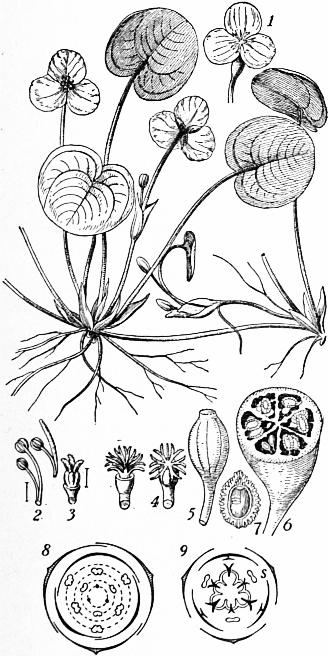
Fig. 1.—Hydrocharis Morsusranae—Frog-bit—male plant.
1, Female flower. 2, Stamens, enlarged. 3, Barren pistil of male flower, enlarged. 4, Pistil of female flower. 5, Fruit. 6, Fruit cut transversely. 7, Seed. 8, 9, Floral diagrams of male and female flowers respectively. s, Rudimentary stamens.
HYDROCHARIDEAE, in botany, a natural order of Monocotyledons, belonging to the series Helobieae. They are water-plants, represented in Britain by frog-bit (Hydrocharis Morsusranae) and water-soldier (Stratiotes aloïdes). The order contains about fifty species in fifteen genera, twelve of which occur in fresh water while three are marine: and includes both floating and submerged forms. Hydrocharis floats on the surface of still water, and has rosettes of kidney-shaped leaves, from among which spring the flower-stalks; stolons bearing new leaf-rosettes are sent out on all sides, the plant thus propagating itself on the same way as the strawberry. Stratiotes aloïdes has a rosette of stiff sword-like leaves, which when the plant is in flower project above the surface; it is also stoloniferous, the young rosettes sinking to the bottom at the beginning of winter and rising again to the surface in the spring. Vallisneria (eel-grass) contains two species, one native of tropical Asia, the other inhabiting the warmer parts of both hemispheres and reaching as far north as south Europe. It grows in the mud at the bottom of fresh water, and the short stem bears a cluster of long, narrow grass-like leaves; new plants are formed at the end of horizontal runners. Another type is represented by Elodea canadensis or water-thyme, which has been introduced into the British Isles from North America. It is a small, submerged plant with long, slender branching stems bearing whorls of narrow toothed leaves; the flowers appear at the surface when mature. Halophila, Enhalus and Thalassia are submerged maritime plants found on tropical coasts, mainly in the Indian and Pacific oceans; Halophila has an elongated stem rooting at the nodes; Enhalus a short, thick rhizome, clothed with black threads resembling horse-hair, the persistent hard-bast strands of the leaves; Thalassia has a creeping rooting stem with upright branches bearing crowded strap-shaped leaves in two rows. The flowers spring from, or are enclosed in, a spathe, and are unisexual and regular, with generally a calyx and corolla, each of three members; the stamens are in whorls of three, the inner whorls are often barren; the two to fifteen carpels form an inferior ovary containing generally numerous ovules on often large, produced, parietal placentas. The fruit is leathery or fleshy, opening irregularly. The seeds contain a large embryo and no endosperm. In Hydrocharis (fig. 1), which is dioecious, the flowers are borne above the surface of the water, have conspicuous white petals, contain honey and are pollinated by insects. Stratiotes has similar flowers which come above the surface only for pollination, becoming submerged again during ripening of the fruit. In Vallisneria (fig. 2), which is also dioecious, the small male flowers are borne in large numbers in short-stalked spathes; the petals are minute and scale-like, and only two of the three stamens are fertile; the flowers become detached before opening and rise to the surface, where the sepals expand and form a float bearing the two projecting semi-erect stamens. The female flowers are solitary and are raised to the surface on a long, spiral stalk; the ovary bears three broad styles, on which some of the large, sticky pollen-grains from the floating male flowers get deposited, (fig. 3). After pollination the female flower becomes drawn below the surface by the spiral contraction of the long stalk, and the fruit ripens near the bottom. Elodea has polygamous flowers (that is, male, female and hermaphrodite), solitary, in slender, tubular spathes; the male flowers become detached and rise to the surface; the females are raised to the surface when mature, and receive the floating pollen from the male. The flowers of Halophila are submerged and apetalous.
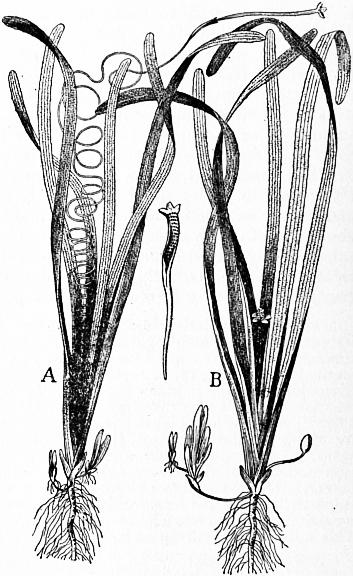
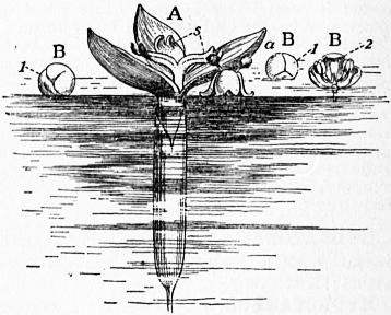
Fig. 2.—Vallisneria spiralis—Eel grass—about 1⁄4 natural size. A, Female plant; B, Male plant. Fig. 3.
The order is a widely distributed one; the marine forms are tropical or subtropical, but the fresh-water genera occur also in the temperate zones.
HYDROCHLORIC ACID, also known in commerce as “spirits of salts” and “muriatic acid,” a compound of hydrogen and chlorine. Its chemistry is discussed under Chlorine, and its manufacture under Alkali Manufacture.
HYDRODYNAMICS (Gr. ὕδωρ, water, δύναμις, strength), the branch of hydromechanics which discusses the motion of fluids (see Hydromechanics).
HYDROGEN [symbol H, atomic weight 1.008 (o = 16)], one of the chemical elements. Its name is derived from Gr. ὕδωρ, water, and γεννάειν, to produce, in allusion to the fact that water is produced when the gas burns in air. Hydrogen appears to have been recognized by Paracelsus in the 16th century; the combustibility of the gas was noticed by Turquet de Mayenne in the 17th century, whilst in 1700 N. Lémery showed that a mixture of hydrogen and air detonated on the application of a light. The first definite experiments concerning the nature of hydrogen were made in 1766 by H. Cavendish, who showed that it was formed when various metals were acted upon by dilute sulphuric or hydrochloric acids. Cavendish called it “inflammable air,” and for some time it was confused with other inflammable gases, all of which were supposed to contain the same inflammable principle, “phlogiston,” in combination with varying amounts of other substances. In 1781 Cavendish showed that water was the only substance produced when hydrogen was burned in air or oxygen, it having been thought previously to this date that other substances were formed during the reaction, A. L. Lavoisier making many experiments with the object of finding an acid among the products of combustion.
Hydrogen is found in the free state in some volcanic gases, in fumaroles, in the carnallite of the Stassfurt potash mines (H. Precht, Ber., 1886, 19, p. 2326), in some meteorites, in certain stars and nebulae, and also in the envelopes of the sun. In combination it is found as a constituent of water, of the gases from certain mineral springs, in many minerals, and in most animal and vegetable tissues. It may be prepared by the electrolysis of acidulated water, by the decomposition of water by various metals or metallic hydrides, and by the action of many metals on acids or on bases. The alkali metals and alkaline earth metals decompose water at ordinary temperatures; magnesium begins to react above 70° C., and zinc at a dull red heat. The decomposition of steam by red hot iron has been studied by H. Sainte-Claire Deville (Comptes rendus, 1870, 70, p. 1105) and by H. Debray (ibid., 1879, 88, p. 1341), who found that at about 1500° C. a condition of equilibrium is reached. H. Moissan (Bull. soc. chim., 1902, 27, p. 1141) has shown that potassium hydride decomposes cold water, with evolution of hydrogen, KH + H2O = KOH + H2. Calcium hydride or hydrolite, prepared by passing hydrogen over heated calcium, decomposes water similarly, 1 gram giving 1 litre of gas; it has been proposed as a commercial source (Prats Aymerich, Abst. J.C.S., 1907, ii. p. 543), as has also aluminium turnings moistened with potassium cyanide and mercuric chloride, which decomposes water regularly at 70°, 1 gram giving 1.3 litres of gas (Mauricheau-Beaupré, Comptes rendus, 1908, 147, p. 310). Strontium hydride behaves similarly. In preparing the gas by the action of metals on acids, dilute sulphuric or hydrochloric acid is taken, and the metals commonly used are zinc or iron. So obtained, it contains many impurities, such as carbon dioxide, nitrogen, oxides of nitrogen, phosphoretted hydrogen, arseniuretted hydrogen, &c., the removal of which is a matter of great difficulty (see E. W. Morley, Amer. Chem. Journ., 1890, 12, p. 460). When prepared by the action of metals on bases, zinc or aluminium and caustic soda or caustic potash are used. Hydrogen may also be obtained by the action of zinc on ammonium salts (the nitrate excepted) (Lorin, Comptes rendus, 1865, 60, p. 745) and by heating the alkali formates or oxalates with caustic potash or soda, Na2C2O4 + 2NaOH = H2 + 2Na2CO3. Technically it is prepared by the action of superheated steam on incandescent coke (see F. Hembert and Henry, Comptes rendus, 1885, 101, p. 797; A. Naumann and C. Pistor, Ber., 1885, 18, p. 1647), or by the electrolysis of a dilute solution of caustic soda (C. Winssinger, Chem. Zeit., 1898, 22, p. 609; “Die Elektrizitäts-Aktiengesellschaft,” Zeit. f. Elektrochem., 1901, 7, p. 857). In the latter method a 15% solution of caustic soda is used, and the electrodes are made of iron; the cell is packed in a wooden box, surrounded with sand, so that the temperature is kept at about 70° C.; the solution is replenished, when necessary, with distilled water. The purity of the gas obtained is about 97%.
Pure hydrogen is a tasteless, colourless and odourless gas of specific gravity 0.06947 (air = 1) (Lord Rayleigh, Proc. Roy. Soc., 1893, p. 319). It may be liquefied, the liquid boiling at −252.68° C. to −252.84° C., and it has also been solidified, the solid melting at −264° C. (J. Dewar, Comptes rendus, 1899, 129, p. 451; Chem. News, 1901, 84, p. 49; see also Liquid Gases). The specific heat of gaseous hydrogen (at constant pressure) is 3.4041 (water = 1), and the ratio of the specific heat at constant pressure to the specific heat at constant volume is 1.3852 (W. C. Röntgen, Pogg. Ann., 1873, 148, p. 580). On the spectrum see Spectroscopy. Hydrogen is only very slightly soluble in water. It diffuses very rapidly through a porous membrane, and through some metals at a red heat (T. Graham, Proc. Roy. Soc., 1867, 15, p. 223; H. Sainte-Claire Deville and L. Troost, Comptes rendus, 1863, 56, p. 977). Palladium and some other metals are capable of absorbing large volumes of hydrogen (especially when the metal is used as a cathode in a water electrolysis apparatus). L. Troost and P. Hautefeuille (Ann. chim. phys., 1874, (5) 2, p. 279) considered that a palladium hydride of composition Pd2H was formed, but the investigations of C. Hoitsema (Zeit. phys. Chem., 1895, 17, p. 1), from the standpoint of the phase rule, do not favour this view, Hoitsema being of the opinion that the occlusion of hydrogen by palladium is a process of continuous absorption. Hydrogen burns with a pale blue non-luminous flame, but will not support the combustion of ordinary combustibles. It forms a highly explosive mixture with air or oxygen, especially when in the proportion of two volumes of hydrogen to one volume of oxygen. H. B. Baker (Proc. Chem. Soc., 1902, 18, p. 40) has shown that perfectly dry hydrogen will not unite with perfectly dry oxygen. Hydrogen combines with fluorine, even at very low temperatures, with great violence; it also combines with carbon, at the temperature of the electric arc. The alkali metals when warmed in a current of hydrogen, at about 360° C., form hydrides of composition RH (R = Na, K, Rb, Cs), (H. Moissan, Bull. soc. chim., 1902, 27, p. 1141); calcium and strontium similarly form hydrides CaH2, SrH2 at a dull red heat (A. Guntz, Comptes rendus, 1901, 133, p. 1209). Hydrogen is a very powerful reducing agent; the gas occluded by palladium being very active in this respect, readily reducing ferric salts to ferrous salts, nitrates to nitrites and ammonia, chlorates to chlorides, &c.
For determinations of the volume ratio with which hydrogen and oxygen combine, see J. B. Dumas, Ann. chim. phys., 1843 (3), 8, p. 189; O. Erdmann and R. F. Marchand, ibid., p. 212; E. H. Keiser, Ber., 1887, 20, p. 2323; J. P. Cooke and T. W. Richards, Amer. Chem. Journ., 1888, 10, p. 191; Lord Rayleigh, Chem. News, 1889, 59, p. 147; E. W. Morley, Zeit. phys. Chem., 1890, 20, p. 417; and S. A. Leduc, Comptes rendus, 1899, 128, p. 1158.
Hydrogen combines with oxygen to form two definite compounds, namely, water (q.v.), H2O, and hydrogen peroxide, H2O2, whilst the existence of a third oxide, ozonic acid, has been indicated.
Hydrogen peroxide, H2O2, was discovered by L. J. Thénard in 1818 (Ann. chim. phys., 8, p. 306). It occurs in small quantities in the atmosphere. It may be prepared by passing a current of carbon dioxide through ice-cold water, to which small quantities of barium peroxide are added from time to time (F. Duprey, Comptes rendus, 1862, 55, p. 736; A. J. Balard, ibid., p. 758), BaO2 + CO2 + H2O = H2O2 + BaCO3. E. Merck (Abst. J.C.S., 1907, ii., p. 859) showed that barium percarbonate, BaCO4, is formed when the gas is in excess; this substance readily yields the peroxide with an acid. Or barium peroxide may be decomposed by hydrochloric, hydrofluoric, sulphuric or silicofluoric acids (L. Crismer, Bull. soc. chim., 1891 (3), 6, p. 24; Hanriot, Comptes rendus, 1885, 100, pp. 56, 172), the peroxide being added in small quantities to a cold dilute solution of the acid. It is necessary that it should be as pure as possible since the commercial product usually contains traces of ferric, manganic and aluminium oxides, together with some silica. To purify the oxide, it is dissolved in dilute hydrochloric acid until the acid is neatly neutralized, the solution is cooled, filtered, and baryta water is added until a faint permanent white precipitate of hydrated barium peroxide appears; the solution is now filtered, and a concentrated solution of baryta water is added to the filtrate, when a crystalline precipitate of hydrated barium peroxide, BaO2·H2O, is thrown down. This is filtered off and well washed with water. The above methods give a dilute aqueous solution of hydrogen peroxide, which may be concentrated somewhat by evaporation over sulphuric acid in vacuo. H. P. Talbot and H. R. Moody (Jour. Anal. Chem., 1892, 6, p. 650) prepared a more concentrated solution from the commercial product, by the addition of a 10% solution of alcohol and baryta water. The solution is filtered, and the barium precipitated by sulphuric acid. The alcohol is removed by distillation in vacuo, and by further concentration in vacuo a solution may be obtained which evolves 580 volumes of oxygen. R. Wolffenstein (Ber., 1894, 27, p. 2307) prepared practically anhydrous hydrogen peroxide (containing 99.1% H2O2) by first removing all traces of dust, heavy metals and alkali from the commercial 3% solution. The solution is then concentrated in an open basis on the water-bath until it contains 48% H2O2. The liquid so obtained is extracted with ether and the ethereal solution distilled under diminished pressure, and finally purified by repeated distillations. W. Staedel (Zeit. f. angew. Chem., 1902, 15, p. 642) has described solid hydrogen peroxide, obtained by freezing concentrated solutions.
Hydrogen peroxide is also found as a product in many chemical actions, being formed when carbon monoxide and cyanogen burn in air (H. B. Dixon); by passing air through solutions of strong bases in the presence of such metals as do not react with the bases to liberate hydrogen; by shaking zinc amalgam with alcoholic sulphuric acid and air (M. Traube, Ber., 1882, 15, p. 659); in the oxidation of zinc, lead and copper in presence of water, and in the electrolysis of sulphuric acid of such strength that it contains two molecules of water to one molecule of sulphuric acid (M. Berthelot, Comptes rendus, 1878, 86, p. 71).
The anhydrous hydrogen peroxide obtained by Wolffenstein boils at 84-85°C. (68 mm.); its specific gravity is 1.4996 (1.5° C.). It is very explosive (W. Spring, Zeit. anorg. Chem., 1895, 8, p. 424). The explosion risk seems to be most marked in the preparations which have been extracted with ether previous to distillation, and J. W. Brühl (Ber., 1895, 28, p. 2847) is of opinion that a very unstable, more highly oxidized product is produced in small quantity in the process. The solid variety prepared by Staedel forms colourless, prismatic crystals which melt at −2° C.; it is decomposed with explosive violence by platinum sponge, and traces of manganese dioxide. The dilute aqueous solution is very unstable, giving up oxygen readily, and decomposing with explosive violence at 100° C. An aqueous solution containing more than 1.5% hydrogen peroxide reacts slightly acid. Towards lupetidin [aa′ dimethyl piperidine, C5H9N(CH3)2] hydrogen peroxide acts as a dibasic acid (A. Marcuse and R. Wolffenstein, Ber., 1901, 34, p. 2430; see also G. Bredig, Zeit. Electrochem., 1901, 7, p. 622). Cryoscopic determinations of its molecular weight show that it is H2O2. [G. Carrara, Rend. della Accad. dei Lincei, 1892 (5), 1, ii. p. 19; W. R. Orndorff and J. White, Amer. Chem. Journ., 1893, 15, p. 347.] Hydrogen peroxide behaves very frequently as a powerful oxidizing agent; thus lead sulphide is converted into lead sulphate in presence of a dilute aqueous solution of the peroxide, the hydroxides of the alkaline earth metals are converted into peroxides of the type MO2·8H2O, titanium dioxide is converted into the trioxide, iodine is liberated from potassium iodide, and nitrites (in alkaline solution) are converted into acid-amides (B. Radziszewski, Ber., 1884, 17, p. 355). In many cases it is found that hydrogen peroxide will only act as an oxidant when in the presence of a catalyst; for example, formic, glycollic, lactic, tartaric, malic, benzoic and other organic acids are readily oxidized in the presence of ferrous sulphate (H. J. H. Fenton, Jour. Chem. Soc., 1900, 77, p. 69), and sugars are readily oxidized in the presence of ferric chloride (O. Fischer and M. Busch, Ber., 1891, 24, p. 1871). It is sought to explain these oxidation processes by assuming that the hydrogen peroxide unites with the compound undergoing oxidation to form an addition compound, which subsequently decomposes (J. H. Kastle and A. S. Loevenhart, Amer. Chem. Journ., 1903, 29, pp. 397, 517). Hydrogen peroxide can also react as a reducing agent, thus silver oxide is reduced with a rapid evolution of oxygen. The course of this reaction can scarcely be considered as definitely settled; M. Berthelot considers that a higher oxide of silver is formed, whilst A. Baeyer and V. Villiger are of opinion that reduced silver is obtained [see Comptes rendus, 1901, 133, p. 555; Ann. Chim. Phys., 1897 (7), 11, p. 217, and Ber., 1901, 34, p. 2769]. Potassium permanganate, in the presence of dilute sulphuric acid, is rapidly reduced by hydrogen peroxide, oxygen being given off, 2KMnO4 + 3H2SO4 + 5H2O2 = K2SO4 + 2MnSO4 + 8H2O + 5O2. Lead peroxide is reduced to the monoxide. Hypochlorous acid and its salts, together with the corresponding bromine and iodine compounds, liberate oxygen violently from hydrogen peroxide, giving hydrochloric, hydrobromic and hydriodic acids (S. Tanatar, Ber., 1899, 32, p. 1013).
On the constitution of hydrogen peroxide see C. F. Schönbein, Jour. prak. Chem., 1858-1868; M. Traube, Ber., 1882-1889; J. W. Brühl, Ber., 1895, 28, p. 2847; 1900, 33, p. 1709; S. Tanatar, Ber., 1903, 36, p. 1893.
Hydrogen peroxide finds application as a bleaching agent, as an antiseptic, for the removal of the last traces of chlorine and sulphur dioxide employed in bleaching, and for various quantitative separations in analytical chemistry (P. Jannasch, Ber., 1893, 26, p. 2908). It may be estimated by titration with potassium permanganate in acid solution; with potassium ferricyanide in alkaline solution, 2K3Fe(CN)6 + 2KOH + H2O2 = 2K4Fe(CN)6 + 2H2O + O2; or by oxidizing arsenious acid in alkaline solution with the peroxide and back titration of the excess of arsenious acid with standard iodine (B. Grützner, Arch. der Pharm., 1899, 237, p. 705). It may be recognized by the violet coloration it gives when added to a very dilute solution of potassium bichromate in the presence of hydrochloric acid; by the orange-red colour it gives with a solution of titanium dioxide in concentrated sulphuric acid; and by the precipitate of Prussian blue formed when it is added to a solution containing ferric chloride and potassium ferricyanide.
Ozonic Acid, H2O4. By the action of ozone on a 40% solution of potassium hydroxide, placed in a freezing mixture, an orange-brown substance is obtained, probably K2O4, which A. Baeyer and V. Villiger (Ber., 1902, 35, p. 3038) think is derived from ozonic acid, produced according to the reaction O3 + H2O = H2O4.
HYDROGRAPHY (Gr. ὕδωρ, water, and γράφειν, to write), the science dealing with all the waters of the earth’s surface, including the description of their physical features and conditions; the preparation of charts and maps showing the position of lakes, rivers, seas and oceans, the contour of the sea-bottom, the position of shallows, deeps, reefs and the direction and volume of currents; a scientific description of the position, volume, configuration, motion and condition of all the waters of the earth. See also Surveying (Nautical) and Ocean and Oceanography. The Hydrographic Department of the British Admiralty, established in 1795, undertakes the making of charts for the admiralty, and is under the charge of the hydrographer to the admiralty (see Chart).
HYDROLYSIS (Gr. ὕδωρ, water, λύειν, to loosen), in chemistry, a decomposition brought about by water after the manner shown in the equation R·X + H·OH = R·H + X·OH. Modern research has proved that such reactions are not occasioned by water acting as H2O, but really by its ions (hydrions and hydroxidions), for the velocity is proportional (in accordance with the law of chemical mass action) to the concentration of these ions. This fact explains the so-called “catalytic” action of acids and bases in decomposing such compounds as the esters. The term “saponification” (Lat. sapo, soap) has the same meaning, but it is more properly restricted to the hydrolysis of the fats, i.e. glyceryl esters of organic acids, into glycerin and a soap (see Chemical Action).