VOLUME XIV SLICE I Husband to Hydrolysis (continued 6)
Reading edition
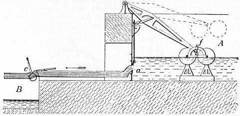
Fig. 73.—Scale 1⁄120.
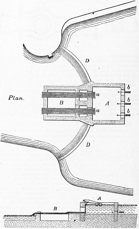
Fig. 74.—Scale 1⁄500.
§ 60. Professor Fleeming Jenkin’s Constant Flow Valve.—In the modules thus far described constant discharge is obtained by varying the area of the orifice through which the water flows. Professor F. Jenkin has contrived a valve in which a constant pressure head is obtained, so that the orifice need not be varied (Roy. Scot. Society of Arts, 1876). Fig. 75 shows a valve of this kind suitable for a 6-in. water main. The water arriving by the main C passes through an equilibrium valve D into the chamber A, and thence through a sluice O, which can be set for any required area of opening, into the discharging main B. The object of the arrangement is to secure a constant difference of pressure between the chambers A and B, so that a constant discharge flows through the stop valve O. The equilibrium valve D is rigidly connected with a plunger P loosely fitted in a diaphragm, separating A from a chamber B2 connected by a pipe B1 with the discharging main B. Any increase of the difference of pressure in A and B will drive the plunger up and close the equilibrium valve, and conversely a decrease of the difference of pressure will cause the descent of the plunger and open the equilibrium valve wider. Thus a constant difference of pressure is obtained in the chambers A and B. Let ω be the area of the plunger in square feet, p the difference of pressure in the chambers A and B in pounds per square foot, w the weight of the plunger and valve. Then if at any moment pω exceeds w the plunger will rise, and if it is less than w the plunger will descend. Apart from friction, and assuming the valve D to be strictly an equilibrium valve, since ω and w are constant, p must be constant also, and equal to w/ω. By making w small and ω large, the difference of pressure required to ensure the working of the apparatus may be made very small. Valves working with a difference of pressure of 1⁄2 in. of water have been constructed.
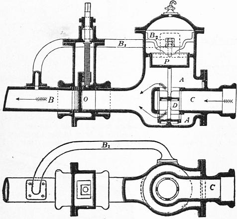
Fig. 75.—Scale 1⁄24.
VI. STEADY FLOW OF COMPRESSIBLE FLUIDS.
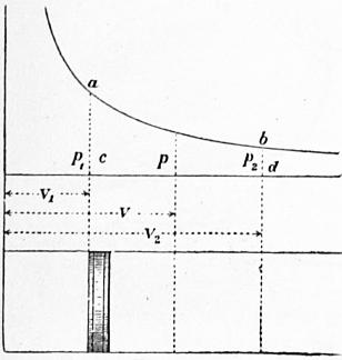
Fig. 76.
§ 61. External Work during the Expansion of Air.—If air expands without doing any external work, its temperature remains constant. This result was first experimentally demonstrated by J. P. Joule. It leads to the conclusion that, however air changes its state, the internal work done is proportional to the change of temperature. When, in expanding, air does work against an external resistance, either heat must be supplied or the temperature falls.
To fix the conditions, suppose 1 ℔ of air confined behind a piston of 1 sq. ft. area (fig. 76). Let the initial pressure be p1 and the volume of the air v1, and suppose this to expand to the pressure p2 and volume v2. If p and v are the corresponding pressure and volume at any intermediate point in the expansion, the work done on the piston during the expansion from v to v + dv is pdv, and the whole work during the expansion from v1 to v2, represented by the area abcd, is
∫v2v1 p dv.
Amongst possible cases two may be selected.
Case 1.—So much heat is supplied to the air during expansion that the temperature remains constant. Hyperbolic expansion.
Then
pv = p1v1.
Work done during expansion per pound of air
= ∫v2v1 p dv = p1v1 ∫v2v1 dv/v
= p1v1 logε v2 / v1 = p1v1 logε p1 / p2.
(1)
Since the weight per cubic foot is the reciprocal of the volume per pound, this may be written
(p1/G1) logε G1/G2.
(1a)
Then the expansion curve ab is a common hyperbola.
Case 2.—No heat is supplied to the air during expansion. Then the air loses an amount of heat equivalent to the external work done and the temperature falls. Adiabatic expansion.
In this case it can be shown that
pvγ = p1v1γ,
where γ is the ratio of the specific heats of air at constant pressure and volume. Its value for air is 1.408, and for dry steam 1.135.
Work done during expansion per pound of air.
= ∫v2v1 p dv = p1v1γ ∫v2v1 dv/vγ
= −{p1v1γ / (γ − 1)} {1/v2γ−1 − 1/v1γ−1} = {p1v1γ / (γ − 1)} {1/v1γ−1 − 1/v2γ−1} = {p1v1 / (γ − 1)} {1 − (v1/v2) γ−1}.
(2)
The value of p1v1 for any given temperature can be found from the data already given.
As before, substituting the weights G1, G2 per cubic foot for the volumes per pound, we get for the work of expansion
(p1/G1) {1/(γ − 1)} {1 − (G2/G1) γ−1},
(2a)
= p1v1 {1/(γ − 1)} {1 − (p2/p1) γ−1/γ}.
(2b)
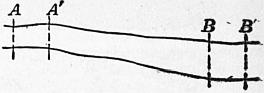
Fig. 77.
§ 62. Modification of the Theorem of Bernoulli for the Case of a Compressible Fluid.—In the application of the principle of work to a filament of compressible fluid, the internal work done by the expansion of the fluid, or absorbed in its compression, must be taken into account. Suppose, as before, that AB (fig. 77) comes to A′B′ in a short time t. Let p1, ω1, v1, G1 be the pressure, sectional area of stream, velocity and weight of a cubic foot at A, and p2, ω2, v2, G2 the same quantities at B. Then, from the steadiness of motion, the weight of fluid passing A in any given time must be equal to the weight passing B:
G1ω1v1t = G2ω2v2t.
Let z1, z2 be the heights of the sections A and B above any given datum. Then the work of gravity on the mass AB in t seconds is
G1ω1v1t (z1 − z2) = W (z1 − z2) t,
where W is the weight of gas passing A or B per second. As in the case of an incompressible fluid, the work of the pressures on the ends of the mass AB is
p1ω1v1t − p2ω2v2t,
= (p1/G1 − p2/G2) Wt.
The work done by expansion of Wt ℔ of fluid between A and B is ∫v2v1 The change of kinetic energy as before is (W/2g) (v22 − v12) t. Hence, equating work to change of kinetic energy,
W (z1 − z2) t + (p1/G1 − p2/G2)Wt + Wt ∫v2v1 p dv = (W/2g) (v22 − v12) t;
∴ z1 + p1/G1 + v12/2g = z2 + p2/G2 + v22/2g − ∫v2v1 p dv.
(1)
Now the work of expansion per pound of fluid has already been given. If the temperature is constant, we get (eq. 1a, § 61)
Z1 + P1/G1 + v12/2g = z2 + p2/G2 + v22/2g − (p1/G1) logε (G1/G2).
But at constant temperature p1/G1 = p2/G2;
∴ z1 + v12/2g = z2 + v22/2g − (p1/G1) logε (p1/p2),
(2)
or, neglecting the difference of level,
(v22 − v12) / 2g = (p1/G1) logε (p1/p2).
(2a)
Similarly, if the expansion is adiabatic (eq. 2a, § 61),
z1 + p1/G1 + v12/2g = z2 + p2/G2 + v22/2g − (p1/G1) {1/(γ − 1) } {1 − (p2/p1)(γ−1)/γ};
(3)
or, neglecting the difference of level,
(v22 − v12)/2g = (p1/G1) [1 + 1/(γ − 1) {1 − (p2/p1)(γ−1)/γ)} ] − p2/G2.
(3a)
It will be seen hereafter that there is a limit in the ratio p1/p2 beyond which these expressions cease to be true.
§ 63. Discharge of Air from an Orifice.—The form of the equation of work for a steady stream of compressible fluid is
z1 + p1/G1 + v12/2g = z2 + p2/G2 + v22/2g − (p1/G1) {1/(γ − 1)} {1 − (p2/p1(γ−1)/γ},
the expansion being adiabatic, because in the flow of the streams of air through an orifice no sensible amount of heat can be communicated from outside.
Suppose the air flows from a vessel, where the pressure is p1 and the velocity sensibly zero, through an orifice, into a space where the pressure is p2. Let v2 be the velocity of the jet at a point where the convergence of the streams has ceased, so that the pressure in the jet is also p2. As air is light, the work of gravity will be small compared with that of the pressures and expansion, so that z1z2 may be neglected. Putting these values in the equation above—
p1/G1 = p2/G2 + v22/2g − (p1/G1) {1/(γ − 1)} {1 − (p2/p1)(γ−1)/γ;
v22/2g = p1/G1 − p2/G2 + (p1/G1) {1/(γ − 1)} {1 − (p2/p1)(γ−1)/γ}
= (p1/G1) {γ/(γ − 1) − (p2/p1)γ−1 /γ / (γ − 1)} − p2/G2.
But
p1/G1γ = p2/G2γ ∴ p2/G2 = (p1/G1) (p2/p1)(γ−1)/γ
v22/2g = (p1/G1) {γ/(γ − 1)} {1 − (p2/p1)(γ−1)/γ};
(1)
or
v22/2g = {γ/(γ − 1)} {(p1/G1) − (p2/G2)};
an equation commonly ascribed to L. J. Weisbach (Civilingenieur, 1856), though it appears to have been given earlier by A. J. C. Barre de Saint Venant and L. Wantzel.
It has already (§ 9, eq. 4a) been seen that
p1/G1 = (p0/G0) (τ1/τ0)
where for air p0 = 2116.8, G0 = .08075 and τ0 = 492.6.
v22/2g = {p0τ1γ / G0τ0 (γ − 1)} {1 − (p2/p1)(γ−1)/γ};
(2)
or, inserting numerical values,
v22/2g = 183.6τ1 {1 − (p2/p1)0.29};
(2a)
which gives the velocity of discharge v2 in terms of the pressure and absolute temperature, p1, τ1, in the vessel from which the air flows, and the pressure p2 in the vessel into which it flows.
Proceeding now as for liquids, and putting ω for the area of the orifice and c for the coefficient of discharge, the volume of air discharged per second at the pressure p2 and temperature τ2 is
Q2 = cωv2 = cω √ [(2gγp1 / (γ − 1) G1) (1 − (p2/p1)(γ−1)/γ)]
= 108.7cω √ [τ1 {1 − (p2/p1)0.29}].
(3)
If the volume discharged is measured at the pressure p1 and absolute temperature τ1 in the vessel from which the air flows, let Q1 be that volume; then
p1Q1γ = p2Q2γ;
Q1 = (p2/p1)1/γ Q2;
Q1 = cω √ [ {2gγp1 / (γ − 1) G1} {(p2/p1)2/γ − (p2/p1)(γ+1)/γ}].
Let
(p2/p1)2/γ − (p2/p1)(γ−1)/γ = (p2/p1)1.41 − (p2/p1)1.7 = ψ; then
Q1 = cω √ [2gγp1ψ / (γ − 1) G1]
= 108.7cω √ (τ1ψ).
(4)
The weight of air at pressure p1 and temperature τ1 is
G1 = p1/53.2τ1 ℔ per cubic foot.
Hence the weight of air discharged is
W = G1Q1 = cω √ [2gγp1G1ψ / (γ − 1)]
= 2.043cωp1 √ (ψ/τ1).
(5)
Weisbach found the following values of the coefficient of discharge c:—
Conoidal mouthpieces of the form of the
contracted vein with effective pressures c =
of .23 to 1.1 atmosphere 0.97 to 0.99
Circular sharp-edged orifices 0.563 ” 0.788
Short cylindrical mouthpieces 0.81 ” 0.84
The same rounded at the inner end 0.92 ” 0.93
Conical converging mouthpieces 0.90 ” 0.99
§ 64. Limit to the Application of the above Formulae.—In the formulae above it is assumed that the fluid issuing from the orifice expands from the pressure p1 to the pressure p2, while passing from the vessel to the section of the jet considered in estimating the area ω. Hence p2 is strictly the pressure in the jet at the plane of the external orifice in the case of mouthpieces, or at the plane of the contracted section in the case of simple orifices. Till recently it was tacitly assumed that this pressure p2 was identical with the general pressure external to the orifice. R. D. Napier first discovered that, when the ratio p2/p1 exceeded a value which does not greatly differ from 0.5, this was no longer true. In that case the expansion of the fluid down to the external pressure is not completed at the time it reaches the plane of the contracted section, and the pressure there is greater than the general external pressure; or, what amounts to the same thing, the section of the jet where the expansion is completed is a section which is greater than the area ccω of the contracted section of the jet, and may be greater than the area ω of the orifice. Napier made experiments with steam which showed that, so long as p2/p1 > 0.5, the formulae above were trustworthy, when p2 was taken to be the general external pressure, but that, if p2/p1 < 0.5, then the pressure at the contracted section was independent of the external pressure and equal to 0.5p1. Hence in such cases the constant value 0.5 should be substituted in the formulae for the ratio of the internal and external pressures p2/p1.
It is easily deduced from Weisbach’s theory that, if the pressure external to an orifice is gradually diminished, the weight of air discharged per second increases to a maximum for a value of the ratio
p2/p1 = {2/(γ + 1)}γ−1/γ = 0.527 for air = 0.58 for dry steam.
For a further decrease of external pressure the discharge diminishes,—a result no doubt improbable. The new view of Weisbach’s formula is that from the point where the maximum is reached, or not greatly differing from it, the pressure at the contracted section ceases to diminish.
A. F. Fliegner showed (Civilingenieur xx., 1874) that for air flowing from well-rounded mouthpieces there is no discontinuity of the law of flow, as Napier’s hypothesis implies, but the curve of flow bends so sharply that Napier’s rule may be taken to be a good approximation to the true law. The limiting value of the ratio p2/p1, for which Weisbach’s formula, as originally understood, ceases to apply, is for air 0.5767; and this is the number to be substituted for p2/p1 in the formulae when p2/p1 falls below that value. For later researches on the flow of air, reference may be made to G. A. Zeuner’s paper (Civilingenieur, 1871), and Fliegner’s papers (ibid., 1877, 1878).
VII. FRICTION OF LIQUIDS.
§ 65. When a stream of fluid flows over a solid surface, or conversely when a solid moves in still fluid, a resistance to the motion is generated, commonly termed fluid friction. It is due to the viscosity of the fluid, but generally the laws of fluid friction are very different from those of simple viscous resistance. It would appear that at all speeds, except the slowest, rotating eddies are formed by the roughness of the solid surface, or by abrupt changes of velocity distributed throughout the fluid; and the energy expended in producing these eddying motions is gradually lost in overcoming the viscosity of the fluid in regions more or less distant from that where they are first produced.
The laws of fluid friction are generally stated thus:—
1. The frictional resistance is independent of the pressure between the fluid and the solid against which it flows. This may be verified by a simple direct experiment. C. H. Coulomb, for instance, oscillated a disk under water, first with atmospheric pressure acting on the water surface, afterwards with the atmospheric pressure removed. No difference in the rate of decrease of the oscillations was observed. The chief proof that the friction is independent of the pressure is that no difference of resistance has been observed in water mains and in other cases, where water flows over solid surfaces under widely different pressures.
2. The frictional resistance of large surfaces is proportional to the area of the surface.
3. At low velocities of not more than 1 in. per second for water, the frictional resistance increases directly as the relative velocity of the fluid and the surface against which it flows. At velocities of 1⁄2 ft. per second and greater velocities, the frictional resistance is more nearly proportional to the square of the relative velocity.
In many treatises on hydraulics it is stated that the frictional resistance is independent of the nature of the solid surface. The explanation of this was supposed to be that a film of fluid remained attached to the solid surface, the resistance being generated between this fluid layer and layers more distant from the surface. At extremely low velocities the solid surface does not seem to have much influence on the friction. In Coulomb’s experiments a metal surface covered with tallow, and oscillated in water, had exactly the same resistance as a clean metal surface, and when sand was scattered over the tallow the resistance was only very slightly increased. The earlier calculations of the resistance of water at higher velocities in iron and wood pipes and earthen channels seemed to give a similar result. These, however, were erroneous, and it is now well understood that differences of roughness of the solid surface very greatly influence the friction, at such velocities as are common in engineering practice. H. P. G. Darcy’s experiments, for instance, showed that in old and incrusted water mains the resistance was twice or sometimes thrice as great as in new and clean mains.
§ 66. Ordinary Expressions for Fluid Friction at Velocities not Extremely Small.—Let f be the frictional resistance estimated in pounds per square foot of surface at a velocity of 1 ft. per second; ω the area of the surface in square feet; and v its velocity in feet per second relatively to the water in which it is immersed. Then, in accordance with the laws stated above, the total resistance of the surface is
R = fωv2
(1)
where f is a quantity approximately constant for any given surface. If
ξ = 2gf/G,
R = ξGωv2/2g,
(2)
where ξ is, like f, nearly constant for a given surface, and is termed the coefficient of friction.
The following are average values of the coefficient of friction for water, obtained from experiments on large plane surfaces, moved in an indefinitely large mass of water.
Coefficient of Friction, ξ Frictional Resistance in ℔ per sq. ft. f
New well-painted iron plate .00489 .00473
Painted and planed plank (Beaufoy) .00350 .00339
Surface of iron ships (Rankine) .00362 .00351
Varnished surface (Froude) .00258 .00250
Fine sand surface (Froude) .00418 .00405
Coarser sand surface (Froude) .00503 .00488
The distance through which the frictional resistance is overcome is v ft. per second. The work expended in fluid friction is therefore given by the equation—
Work expended = fωv3 foot-pounds per second = ξGωv3/2g ” ”
(3).
The coefficient of friction and the friction per square foot of surface can be indirectly obtained from observations of the discharge of pipes and canals. In obtaining them, however, some assumptions as to the motion of the water must be made, and it will be better therefore to discuss these values in connexion with the cases to which they are related.
Many attempts have been made to express the coefficient of friction in a form applicable to low as well as high velocities. The older hydraulic writers considered the resistance termed fluid friction to be made up of two parts,—a part due directly to the distortion of the mass of water and proportional to the velocity of the water relatively to the solid surface, and another part due to kinetic energy imparted to the water striking the roughnesses of the solid surface and proportional to the square of the velocity. Hence they proposed to take
ξ = α + β/v
in which expression the second term is of greatest importance at very low velocities, and of comparatively little importance at velocities over about 1⁄2 ft. per second. Values of ξ expressed in this and similar forms will be given in connexion with pipes and canals.
All these expressions must at present be regarded as merely empirical expressions serving practical purposes.
The frictional resistance will be seen to vary through wider limits than these expressions allow, and to depend on circumstances of which they do not take account.
§ 67. Coulomb’s Experiments.—The first direct experiments on fluid friction were made by Coulomb, who employed a circular disk suspended by a thin brass wire and oscillated in its own plane. His experiments were chiefly made at very low velocities. When the disk is rotated to any given angle, it oscillates under the action of its inertia and the torsion of the wire. The oscillations diminish gradually in consequence of the work done in overcoming the friction of the disk. The diminution furnishes a means of determining the friction.
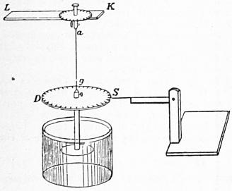
Fig. 78.
Fig. 78 shows Coulomb’s apparatus. LK supports the wire and disk: ag is the brass wire, the torsion of which causes the oscillations; DS is a graduated disk serving to measure the angles through which the apparatus oscillates. To this the friction disk is rigidly attached hanging in a vessel of water. The friction disks were from 4.7 to 7.7 in. diameter, and they generally made one oscillation in from 20 to 30 seconds, through angles varying from 360° to 6°. When the velocity of the circumference of the disk was less than 6 in. per second, the resistance was sensibly proportional to the velocity.
Beaufoy’s Experiments.—Towards the end of the 18th century Colonel Mark Beaufoy (1764-1827) made an immense mass of experiments on the resistance of bodies moved through water (Nautical and Hydraulic Experiments, London, 1834). Of these the only ones directly bearing on surface friction were some made in 1796 and 1798. Smooth painted planks were drawn through water and the resistance measured. For two planks differing in area by 46 sq. ft., at a velocity of 10 ft. per second, the difference of resistance, measured on the difference of area, was 0.339 ℔ per square foot. Also the resistance varied as the 1.949th power of the velocity.
§ 68. Froude’s Experiments.—The most important direct experiments on fluid friction at ordinary velocities are those made by William Froude (1810-1879) at Torquay. The method adopted in these experiments was to tow a board in a still water canal, the velocity and the resistance being registered by very ingenious recording arrangements. The general arrangement of the apparatus is shown in fig. 79. AA is the board the resistance of which is to be determined. B is a cutwater giving a fine entrance to the plane surfaces of the board. CC is a bar to which the board AA is attached, and which is suspended by a parallel motion from a carriage running on rails above the still water canal. G is a link by which the resistance of the board is transmitted to a spiral spring H. A bar I rigidly connects the other end of the spring to the carriage. The dotted lines K, L indicate the position of a couple of levers by which the extension of the spring is caused to move a pen M, which records the extension on a greatly increased scale, by a line drawn on the paper cylinder N. This cylinder revolves at a speed proportionate to that of the carriage, its motion being obtained from the axle of the carriage wheels. A second pen O, receiving jerks at every second and a quarter from a clock P, records time on the paper cylinder. The scale for the line of resistance is ascertained by stretching the spiral spring by known weights. The boards used for the experiment were 3⁄16 in. thick, 19 in. deep, and from 1 to 50 ft. in length, cutwater included. A lead keel counteracted the buoyancy of the board. The boards were covered with various substances, such as paint, varnish, Hay’s composition, tinfoil, &c., so as to try the effect of different degrees of roughness of surface. The results obtained by Froude may be summarized as follows:—
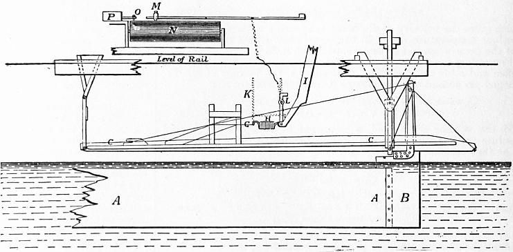
Fig. 79.
1. The friction per square foot of surface varies very greatly for different surfaces, being generally greater as the sensible roughness of the surface is greater. Thus, when the surface of the board was covered as mentioned below, the resistance for boards 50 ft. long, at 10 ft. per second, was—
Tinfoil or varnish 0.25 ℔ per sq. ft.
Calico 0.47 ” ”
Fine sand 0.405 ” ”
Coarser sand 0.488 ” ”
2. The power of the velocity to which the friction is proportional varies for different surfaces. Thus, with short boards 2 ft. long,
For tinfoil the resistance varied as v2.16. For other surfaces the resistance varied as v2.00.
With boards 50 ft. long,
For varnish or tinfoil the resistance varied as v1.83. For sand the resistance varied as v2.00.
3. The average resistance per square foot of surface was much greater for short than for long boards; or, what is the same thing, the resistance per square foot at the forward part of the board was greater than the friction per square foot of portions more sternward. Thus,
Mean Resistance in ℔ per sq. ft.
Varnished surface 2 ft. long 0.41
50 ” 0.25
Fine sand surface 2 ” 0.81
50 ” 0.405
This remarkable result is explained thus by Froude: “The portion of surface that goes first in the line of motion, in experiencing resistance from the water, must in turn communicate motion to the water, in the direction in which it is itself travelling. Consequently the portion of surface which succeeds the first will be rubbing, not against stationary water, but against water partially moving in its own direction, and cannot therefore experience so much resistance from it.”
§ 69. The following table gives a general statement of Froude’s results. In all the experiments in this table, the boards had a fine cutwater and a fine stern end or run, so that the resistance was entirely due to the surface. The table gives the resistances per square foot in pounds, at the standard speed of 600 feet per minute, and the power of the speed to which the friction is proportional, so that the resistance at other speeds is easily calculated.
Length of Surface, or Distance from Cutwater, in feet.
2 ft. 8 ft. 20 ft. 50 ft.
A B C A B C A B C A B C
Varnish 2.00 .41 .390 1.85 .325 .264 1.85 .278 .240 1.83 .250 .226
Paraffin .. .38 .370 1.94 .314 .260 1.93 .271 .237 .. .. ..
Tinfoil 2.16 .30 .295 1.99 .278 .263 1.90 .262 .244 1.83 .246 .232
Calico 1.93 .87 .725 1.92 .626 .504 1.89 .531 .447 1.87 .474 .423
Fine sand 2.00 .81 .690 2.00 .583 .450 2.00 .480 .384 2.06 .405 .337
Medium sand 2.00 .90 .730 2.00 .625 .488 2.00 .534 .465 2.00 .488 .456
Coarse sand 2.00 1.10 .880 2.00 .714 .520 2.00 .588 .490 .. .. ..
Columns A give the power of the speed to which the resistance is approximately proportional.
Columns B give the mean resistance per square foot of the whole surface of a board of the lengths stated in the table.
Columns C give the resistance in pounds of a square foot of surface at the distance sternward from the cutwater stated in the heading.
Although these experiments do not directly deal with surfaces of greater length than 50 ft., they indicate what would be the resistances of longer surfaces. For at 50 ft. the decrease of resistance for an increase of length is so small that it will make no very great difference in the estimate of the friction whether we suppose it to continue to diminish at the same rate or not to diminish at all. For a varnished surface the friction at 10 ft. per second diminishes from 0.41 to 0.32 ℔ per square foot when the length is increased from 2 to 8 ft., but it only diminishes from 0.278 to 0.250 ℔ per square foot for an increase from 20 ft. to 50 ft.
If the decrease of friction sternwards is due to the generation of a current accompanying the moving plane, there is not at first sight any reason why the decrease should not be greater than that shown by the experiments. The current accompanying the board might be assumed to gain in volume and velocity sternwards, till the velocity was nearly the same as that of the moving plane and the friction per square foot nearly zero. That this does not happen appears to be due to the mixing up of the current with the still water surrounding it. Part of the water in contact with the board at any point, and receiving energy of motion from it, passes afterwards to distant regions of still water, and portions of still water are fed in towards the board to take its place. In the forward part of the board more kinetic energy is given to the current than is diffused into surrounding space, and the current gains in velocity. At a greater distance back there is an approximate balance between the energy communicated to the water and that diffused. The velocity of the current accompanying the board becomes constant or nearly constant, and the friction per square foot is therefore nearly constant also.
§ 70. Friction of Rotating Disks.—A rotating disk is virtually a surface of unlimited extent and it is convenient for experiments on friction with different surfaces at different speeds. Experiments carried out by Professor W. C. Unwin (Proc. Inst. Civ. Eng. lxxx.) are useful both as illustrating the laws of fluid friction and as giving data for calculating the resistance of the disks of turbines and centrifugal pumps. Disks of 10, 15 and 20 in. diameter fixed on a vertical shaft were rotated by a belt driven by an engine. They were enclosed in a cistern of water between parallel top and bottom fixed surfaces. The cistern was suspended by three fine wires. The friction of the disk is equal to the tendency of the cistern to rotate, and this was measured by balancing the cistern by a fine silk cord passing over a pulley and carrying a scale pan in which weights could be placed.
If ω is an element of area on the disk moving with the velocity v, the friction on this element is fωvn, where f and n are constant for any given kind of surface. Let α be the angular velocity of rotation, R the radius of the disk. Consider a ring of the surface between r and r + dr. Its area is 2πrdr, its velocity αr and the friction of this ring is f2πrdrαnrn. The moment of the friction about the axis of rotation is 2παnfrn+2 dr, and the total moment of friction for the two sides of the disk is
M = 4παnf ∫R0 rn+2 dr = {4παn/(n + 3) } fRn+3.
If N is the number of revolutions per sec.,
M = {2n+2 πn+1 Nn/(n + 3) } fRn+3,
and the work expended in rotating the disk is
Mα = {2n+3 πn+2 Nn+1/(n + 3) } fRn+3 foot ℔ per sec.
The experiments give directly the values of M for the disks corresponding to any speed N. From these the values of f and n can be deduced, f being the friction per square foot at unit velocity. For comparison with Froude’s results it is convenient to calculate the resistance at 10 ft. per second, which is F = f10n.
The disks were rotated in chambers 22 in. diameter and 3, 6 and 12 in. deep. In all cases the friction of the disks increased a little as the chamber was made larger. This is probably due to the stilling of the eddies against the surface of the chamber and the feeding back of the stilled water to the disk. Hence the friction depends not only on the surface of the disk but to some extent on the surface of the chamber in which it rotates. If the surface of the chamber is made rougher by covering with coarse sand there is also an increase of resistance.
For the smoother surfaces the friction varied as the 1.85th power of the velocity. For the rougher surfaces the power of the velocity to which the resistance was proportional varied from 1.9 to 2.1. This is in agreement with Froude’s results.
Experiments with a bright brass disk showed that the friction decreased with increase of temperature. The diminution between 41° and 130° F. amounted to 18%. In the general equation M = cNn for any given disk,
ct = 0.1328 (1 − 0.0021t),
where ct is the value of c for a bright brass disk 0.85 ft. in diameter at a temperature t° F.
The disks used were either polished or made rougher by varnish or by varnish and sand. The following table gives a comparison of the results obtained with the disks and Froude’s results on planks 50 ft. long. The values given are the resistances per square foot at 10 ft. per sec.
Froude’s Experiments. Disk Experiments.
Tinfoil surface 0.232 Bright brass 0.202 to 0.229
Varnish 0.226 Varnish 0.220 to 0.233
Fine sand 0.337 Fine sand 0.339
Medium sand 0.456 Very coarse sand 0.587 to 0.715
VIII. STEADY FLOW OF WATER IN PIPES OF UNIFORM SECTION.
§ 71. The ordinary theory of the flow of water in pipes, on which all practical formulae are based, assumes that the variation of velocity at different points of any cross section may be neglected. The water is considered as moving in plane layers, which are driven through the pipe against the frictional resistance, by the difference of pressure at or elevation of the ends of the pipe. If the motion is steady the velocity at each cross section remains the same from moment to moment, and if the cross sectional area is constant the velocity at all sections must be the same. Hence the motion is uniform. The most important resistance to the motion of the water is the surface friction of the pipe, and it is convenient to estimate this independently of some smaller resistances which will be accounted for presently.
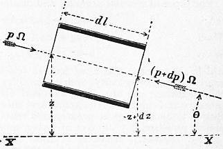
Fig. 80.
In any portion of a uniform pipe, excluding for the present the ends of the pipe, the water enters and leaves at the same velocity. For that portion therefore the work of the external forces and of the surface friction must be equal. Let fig. 80 represent a very short portion of the pipe, of length dl, between cross sections at z and z + dz ft. above any horizontal datum line xx, the pressures at the cross sections being p and p + dp ℔ per square foot. Further, let Q be the volume of flow or discharge of the pipe per second, Ω the area of a normal cross section, and χ the perimeter of the pipe. The Q cubic feet, which flow through the space considered per second, weigh GQ ℔, and fall through a height −dz ft. The work done by gravity is then
−GQ dz;
a positive quantity if dz is negative, and vice versa. The resultant pressure parallel to the axis of the pipe is p − (p + dp) = −dp ℔ per square foot of the cross section. The work of this pressure on the volume Q is
−Q dp.
The only remaining force doing work on the system is the friction against the surface of the pipe. The area of that surface is χdl.
The work expended in overcoming the frictional resistance per second is (see § 66, eq. 3)
−ζGχ dl v3/2g,
or, since Q = Ωv,
−ζG (χ/Ω) Q (v2/2g) dl;
the negative sign being taken because the work is done against a resistance. Adding all these portions of work, and equating the result to zero, since the motion is uniform,—
−GQ dz − Q dp − ζG (χ/Ω) Q (v2/2g) dl = 0.
Dividing by GQ,
dz + dp/G + ζ (χ/Ω) (v2/2g) dl = 0.
Integrating,
z + p/G + ζ (χ/Ω) (v2/2g) l = constant.
(1)
§ 72. Let A and B (fig. 81) be any two sections of the pipe for which p, z, l have the values p1, z1, l1, and p2, z2, l2, respectively. Then
z1 + p1/G + ζ (χ/Ω) (v2/2g) l1 = z2 + p2/G + ζ (χ/Ω) (v2/2g) l2;
or, if l2 − l1 = L, rearranging the terms,
ζv2/2g = (1/L) {(z1 + p1/G) − (z2 + p2/G)} Ω/χ.
(2)
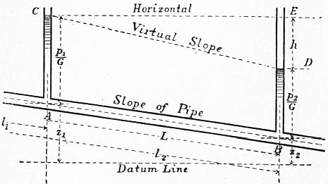
Fig. 81.
Suppose pressure columns introduced at A and B. The water will rise in those columns to the heights p1/G and p2/G due to the pressures p1 and p2 at A and B. Hence (z1 + p1/G) − (z2 + p2/G) is the quantity represented in the figure by DE, the fall of level of the pressure columns, or virtual fall of the pipe. If there were no friction in the pipe, then by Bernoulli’s equation there would be no fall of level of the pressure columns, the velocity being the same at A and B. Hence DE or h is the head lost in friction in the distance AB. The quantity DE/AB = h/L is termed the virtual slope of the pipe or virtual fall per foot of length. It is sometimes termed very conveniently the relative fall. It will be denoted by the symbol i.
The quantity Ω/χ which appears in many hydraulic equations is called the hydraulic mean radius of the pipe. It will be denoted by m.
Introducing these values,
ζv2/2g = mh/L = mi.
(3)
For pipes of circular section, and diameter d,
m = Ω/χ = 1⁄4πd2/πd = 1⁄4d.
Then
ζv2/2g = 1⁄4dh/L = 1⁄4 di;
(4)
or
h = ζ (4L/d) (v2/2g);
(4a)
which shows that the head lost in friction is proportional to the head due to the velocity, and is found by multiplying that head by the coefficient 4ζL/d. It is assumed above that the atmospheric pressure at C and D is the same, and this is usually nearly the case. But if C and D are at greatly different levels the excess of barometric pressure at C, in feet of water, must be added to p2/G.
§ 73. Hydraulic Gradient or Line of Virtual Slope.—Join CD. Since the head lost in friction is proportional to L, any intermediate pressure column between A and B will have its free surface on the line CD, and the vertical distance between CD and the pipe at any point measures the pressure, exclusive of atmospheric pressure, in the pipe at that point. If the pipe were laid along the line CD instead of AB, the water would flow at the same velocity by gravity without any change of pressure from section to section. Hence CD is termed the virtual slope or hydraulic gradient of the pipe. It is the line of free surface level for each point of the pipe.
If an ordinary pipe, connecting reservoirs open to the air, rises at any joint above the line of virtual slope, the pressure at that point is less than the atmospheric pressure transmitted through the pipe. At such a point there is a liability that air may be disengaged from the water, and the flow stopped or impeded by the accumulation of air. If the pipe rises more than 34 ft. above the line of virtual slope, the pressure is negative. But as this is impossible, the continuity of the flow will be broken.
If the pipe is not straight, the line of virtual slope becomes a curved line, but since in actual pipes the vertical alterations of level are generally small, compared with the length of the pipe, distances measured along the pipe are sensibly proportional to distances measured along the horizontal projection of the pipe. Hence the line of hydraulic gradient may be taken to be a straight line without error of practical importance.
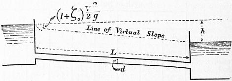
Fig. 82.
§ 74. Case of a Uniform Pipe connecting two Reservoirs, when all the Resistances are taken into account.—Let h (fig. 82) be the difference of level of the reservoirs, and v the velocity, in a pipe of length L and diameter d. The whole work done per second is virtually the removal of Q cub. ft. of water from the surface of the upper reservoir to the surface of the lower reservoir, that is GQh foot-pounds. This is expended in three ways. (1) The head v2/2g, corresponding to an expenditure of GQv2/2g foot-pounds of work, is employed in giving energy of motion to the water. This is ultimately wasted in eddying motions in the lower reservoir. (2) A portion of head, which experience shows may be expressed in the form ζ0v2/2g, corresponding to an expenditure of GQζ0v2/2g foot-pounds of work, is employed in overcoming the resistance at the entrance to the pipe. (3) As already shown the head expended in overcoming the surface friction of the pipe is ζ(4L/d) (v2/2g) corresponding to GQζ (4L/d) (v2/2g) foot-pounds of work. Hence
GQh = GQv2/2g + GQζ0v2/2g + GQζ·4L·v2/d·2g;
h = (1 + ζ0 + ζ·4L/d) v2/2g. v = 8.025 √ [hd / {(1 + ζ0)d + 4ζL} ].
(5)
If the pipe is bell-mouthed, ζ0 is about = .08. If the entrance to the pipe is cylindrical, ζ0 = 0.505. Hence 1 + ζ0 = 1.08 to 1.505. In general this is so small compared with ζ4L/d that, for practical calculations, it may be neglected; that is, the losses of head other than the loss in surface friction are left out of the reckoning. It is only in short pipes and at high velocities that it is necessary to take account of the first two terms in the bracket, as well as the third. For instance, in pipes for the supply of turbines, v is usually limited to 2 ft. per second, and the pipe is bellmouthed. Then 1.08v2/2g = 0.067 ft. In pipes for towns’ supply v may range from 2 to 41⁄2 ft. per second, and then 1.5v2/2g = 0.1 to 0.5 ft. In either case this amount of head is small compared with the whole virtual fall in the cases which most commonly occur.
When d and v or d and h are given, the equations above are solved quite simply. When v and h are given and d is required, it is better to proceed by approximation. Find an approximate value of d by assuming a probable value for ζ as mentioned below. Then from that value of d find a corrected value for ζ and repeat the calculation.
The equation above may be put in the form
h = (4ζ/d) [{ (1 + ζ0) d/4ζ} + L] v2/2g;
(6)
from which it is clear that the head expended at the mouthpiece is equivalent to that of a length
(1 + ζ0) d/4ζ
of the pipe. Putting 1 + ζ0 = 1.505 and ζ = 0.01, the length of pipe equivalent to the mouthpiece is 37.6d nearly. This may be added to the actual length of the pipe to allow for mouthpiece resistance in approximate calculations.
§ 75. Coefficient of Friction for Pipes discharging Water.—From the average of a large number of experiments, the value of ζ for ordinary iron pipes is
ζ = 0.007567.
(7)
But practical experience shows that no single value can be taken applicable to very different cases. The earlier hydraulicians occupied themselves chiefly with the dependence of ζ on the velocity. Having regard to the difference of the law of resistance at very low and at ordinary velocities, they assumed that ζ might be expressed in the form
ζ = a + β/v.
The following are the best numerical values obtained for ζ so expressed:—
α β
R. de Prony (from 51 experiments) 0.006836 0.001116
J. F. d’Aubuisson de Voisins 0.00673 0.001211
J. A. Eytelwein 0.005493 0.00143
Weisbach proposed the formula
4ζ = α + β/√v = 0.003598 + 0.004289/√v.
(8)
§ 76. Darcy’s Experiments on Friction in Pipes.—All previous experiments on the resistance of pipes were superseded by the remarkable researches carried out by H. P. G. Darcy (1803-1858), the Inspector-General of the Paris water works. His experiments were carried out on a scale, under a variation of conditions, and with a degree of accuracy which leaves little to be desired, and the results obtained are of very great practical importance. These results may be stated thus:—
1. For new and clean pipes the friction varies considerably with the nature and polish of the surface of the pipe. For clean cast iron it is about 11⁄2 times as great as for cast iron covered with pitch.
2. The nature of the surface has less influence when the pipes are old and incrusted with deposits, due to the action of the water. Thus old and incrusted pipes give twice as great a frictional resistance as new and clean pipes. Darcy’s coefficients were chiefly determined from experiments on new pipes. He doubles these coefficients for old and incrusted pipes, in accordance with the results of a very limited number of experiments on pipes containing incrustations and deposits.
3. The coefficient of friction may be expressed in the form ζ = α + β/v; but in pipes which have been some time in use it is sufficiently accurate to take ζ = α1 simply, where α1 depends on the diameter of the pipe alone, but α and β on the other hand depend both on the diameter of the pipe and the nature of its surface. The following are the values of the constants.
For pipes which have been some time in use, neglecting the term depending on the velocity;
ζ = α (1 + β/d).
(9)
α β
For drawn wrought-iron or smooth cast-iron pipes .004973 .084
For pipes altered by light incrustations .00996 .084
These coefficients may be put in the following very simple form, without sensibly altering their value:—
For clean pipes ζ = .005 (1 + 1/12d)
For slightly incrusted pipes ζ = .01 (1 + 1/12d)
(9a)
Darcy’s Value of the Coefficient of Friction ζ for Velocities not less than 4 in. per second.
Diameter of Pipe in Inches. ζ Diameter of Pipe in Inches. ζ
New Pipes. Incrusted Pipes. New Pipes. Incrusted Pipes.
2 0.00750 0.01500 18 .00528 .01056
3 .00667 .01333 21 .00524 .01048
4 .00625 .01250 24 .00521 .01042
5 .00600 .01200 27 .00519 .01037
6 .00583 .01167 30 .00517 .01033
7 .00571 .01143 36 .00514 .01028
8 .00563 .01125 42 .00512 .01024
9 .00556 .01111 54 .00509 .01019
15 .00533 .01067
These values of ζ are, however, not exact for widely differing velocities. To embrace all cases Darcy proposed the expression
ζ = (α + α1/d) + (β + β1/d2) / v;
(10)
which is a modification of Coulomb’s, including terms expressing the influence of the diameter and of the velocity. For clean pipes Darcy found these values
α = .004346 α1 = .0003992 β = .0010182 β1 = .000005205.
It has become not uncommon to calculate the discharge of pipes by the formula of E. Ganguillet and W. R. Kutter, which will be discussed under the head of channels. For the value of c in the relation v = c √(mi), Ganguillet and Kutter take
c = 41.6 + 1.811/n + .00281/i
1 + [ (41.6 + .00281/i) (n/√m) ]
where n is a coefficient depending only on the roughness of the pipe. For pipes uncoated as ordinarily laid n = 0.013. The formula is very cumbrous, its form is not rationally justifiable and it is not at all clear that it gives more accurate values of the discharge than simpler formulae.
§ 77. Later Investigations on Flow in Pipes.—The foregoing statement gives the theory of flow in pipes so far as it can be put in a simple rational form. But the conditions of flow are really more complicated than can be expressed in any rational form. Taking even selected experiments the values of the empirical coefficient ζ range from 0.16 to 0.0028 in different cases. Hence means of discriminating the probable value of ζ are necessary in using the equations for practical purposes. To a certain extent the knowledge that ζ decreases with the size of the pipe and increases very much with the roughness of its surface is a guide, and Darcy’s method of dealing with these causes of variation is very helpful. But a further difficulty arises from the discordance of the results of different experiments. For instance F. P. Stearns and J. M. Gale both experimented on clean asphalted cast-iron pipes, 4 ft. in diameter. According to one set of gaugings ζ = .0051, and according to the other ζ = .0031. It is impossible in such cases not to suspect some error in the observations or some difference in the condition of the pipes not noticed by the observers.
It is not likely that any formula can be found which will give exactly the discharge of any given pipe. For one of the chief factors in any such formula must express the exact roughness of the pipe surface, and there is no scientific measure of roughness. The most that can be done is to limit the choice of the coefficient for a pipe within certain comparatively narrow limits. The experiments on fluid friction show that the power of the velocity to which the resistance is proportional is not exactly the square. Also in determining the form of his equation for ζ Darcy used only eight out of his seventeen series of experiments, and there is reason to think that some of these were exceptional. Barré de Saint-Venant was the first to propose a formula with two constants,
dh/4l = mVn,
where m and n are experimental constants. If this is written in the form
log m + n log v = log (dh/4l),
we have, as Saint-Venant pointed out, the equation to a straight line, of which m is the ordinate at the origin and n the ratio of the slope. If a series of experimental values are plotted logarithmically the determination of the constants is reduced to finding the straight line which most nearly passes through the plotted points. Saint-Venant found for n the value of 1.71. In a memoir on the influence of temperature on the movement of water in pipes (Berlin, 1854) by G. H. L. Hagen (1797-1884) another modification of the Saint-Venant formula was given. This is h/l = mvn/dx, which involves three experimental coefficients. Hagen found n = 1.75; x = 1.25; and m was then nearly independent of variations of v and d. But the range of cases examined was small. In a remarkable paper in the Trans. Roy. Soc., 1883, Professor Osborne Reynolds made much clearer the change from regular stream line motion at low velocities to the eddying motion, which occurs in almost all the cases with which the engineer has to deal. Partly by reasoning, partly by induction from the form of logarithmically plotted curves of experimental results, he arrived at the general equation h/l = c (vn/d3−n) P2−n, where n = l for low velocities and n = 1.7 to 2 for ordinary velocities. P is a function of the temperature. Neglecting variations of temperature Reynold’s formula is identical with Hagen’s if x = 3 − n. For practical purposes Hagen’s form is the more convenient.
Values of Index of Velocity.
Surface of Pipe. Authority. Diameter of Pipe in Metres. Values of n.
Tin plate Bossut .036 1.697 1.72
.054 1.730
Wrought iron (gas pipe) Hamilton Smith .0159 1.756 1.75
.0267 1.770
Lead Darcy .014 1.866 1.77
.027 1.755
.041 1.760
Clean brass Mair .036 1.795 1.795
Asphalted Hamilton Smith .0266 1.760 1.85
Lampe. .4185 1.850
W. W. Bonn .306 1.582
Stearns 1.219 1.880
Riveted wrought iron Hamilton Smith .2776 1.804 1.87
.3219 1.892
.3749 1.852
Wrought iron (gas pipe) Darcy .0122 1.900 1.87
.0266 1.899
.0395 1.838
New cast iron Darcy .0819 1.950 1.95
.137 1.923
.188 1.957
.50 1.950
Cleaned cast iron Darcy .0364 1.835 2.00
.0801 2.000
.2447 2.000
.397 2.07
Incrusted cast iron Darcy .0359 1.980 2.00
.0795 1.990
.2432 1.990
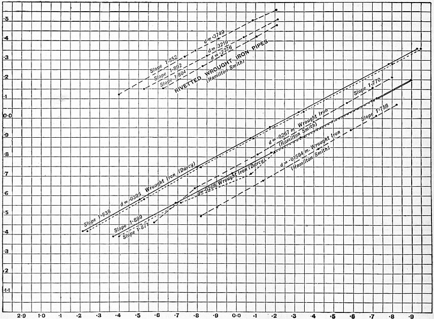
Fig. 83.
In 1886, Professor W. C. Unwin plotted logarithmically all the most trustworthy experiments on flow in pipes then available.5 Fig. 83 gives one such plotting. The results of measuring the slopes of the lines drawn through the plotted points are given in the table.
It will be seen that the values of the index n range from 1.72 for the smoothest and cleanest surface, to 2.00 for the roughest. The numbers after the brackets are rounded off numbers.
The value of n having been thus determined, values of m/dx were next found and averaged for each pipe. These were again plotted logarithmically in order to find a value for x. The lines were not very regular, but in all cases the slope was greater than 1 to 1, so that the value of x must be greater than unity. The following table gives the results and a comparison of the value of x and Reynolds’s value 3 − n.
Kind of Pipe. n 3 − n x
Tin plate 1.72 1.28 1.100
Wrought iron (Smith) 1.75 1.25 1.210
Asphalted pipes 1.85 1.15 1.127
Wrought iron (Darcy) 1.87 1.13 1.680
Riveted wrought iron 1.87 1.13 1.390
New cast iron 1.95 1.05 1.168
Cleaned cast iron 2.00 1.00 1.168
Incrusted cast iron 2.00 1.00 1.160
With the exception of the anomalous values for Darcy’s wrought-iron pipes, there is no great discrepancy between the values of x and 3 − n, but there is no appearance of relation in the two quantities. For the present it appears preferable to assume that x is independent of n.
It is now possible to obtain values of the third constant m, using the values found for n and x. The following table gives the results, the values of m being for metric measures.
Here, considering the great range of diameters and velocities in the experiments, the constancy of m is very satisfactorily close. The asphalted pipes give rather variable values. But, as some of these were new and some old, the variation is, perhaps, not surprising. The incrusted pipes give a value of m quite double that for new pipes but that is perfectly consistent with what is known of fluid friction in other cases.
Kind of Pipe. Diameter in Metres. Value of m. Mean Value of m. Authority.
Tin plate 0.036 .01697 .01686 Bossut
0.054 .01676
Wrought iron 0.016 .01302 .01310 Hamilton Smith
0.027 .01319
Asphalted pipes 0.027 .01749 .01831 Hamilton Smith
0.306 .02058 W. W. Bonn
0.306 .02107 W. W. Bonn
0.419 .01650 Lampe
1.219 .01317 Stearns
1.219 .02107 Gale
Riveted wrought iron 0.278 .01370 .01403 Hamilton Smith
0.322 .01440
0.375 .01390
0.432 .01368
0.657 .01448
New cast iron 0.082 .01725 .01658 Darcy
0.137 .01427
0.188 .01734
0.500 .01745
Cleaned cast iron 0.080 .01979 .01994 Darcy
0.245 .02091
0.297 .01913
Incrusted cast iron 0.036 .03693 .03643 Darcy
0.080 .03530
0.243 .03706
General Mean Values of Constants.
The general formula (Hagen’s)—h/l = mvn/dx·2g—can therefore be taken to fit the results with convenient closeness, if the following mean values of the coefficients are taken, the unit being a metre:—
Kind of Pipe. m x n
Tin plate .0169 1.10 1.72
Wrought iron .0131 1.21 1.75
Asphalted iron .0183 1.127 1.85
Riveted wrought iron .0140 1.390 1.87
New cast iron .0166 1.168 1.95
Cleaned cast iron .0199 1.168 2.0
Incrusted cast iron .0364 1.160 2.0
The variation of each of these coefficients is within a comparatively narrow range, and the selection of the proper coefficient for any given case presents no difficulty, if the character of the surface of the pipe is known.
It only remains to give the values of these coefficients when the quantities are expressed in English feet. For English measures the following are the values of the coefficients:—
Kind of Pipe. m x n
Tin plate .0265 1.10 1.72
Wrought iron .0226 1.21 1.75
Asphalted iron .0254 1.127 1.85
Riveted wrought iron .0260 1.390 1.87
New cast iron .0215 1.168 1.95
Cleaned cast iron .0243 1.168 2.0
Incrusted cast iron .0440 1.160 2.0
§ 78. Distribution of Velocity in the Cross Section of a Pipe.—Darcy made experiments with a Pitot tube in 1850 on the velocity at different points in the cross section of a pipe. He deduced the relation
V − v = 11.3 (r3/2/R) √i,
where V is the velocity at the centre and v the velocity at radius r in a pipe of radius R with a hydraulic gradient i. Later Bazin repeated the experiments and extended them (Mém. de l’Académie des Sciences, xxxii. No. 6). The most important result was the ratio of mean to central velocity. Let b = Ri/U2, where U is the mean velocity in the pipe; then V/U = 1 + 9.03 √b. A very useful result for practical purposes is that at 0.74 of the radius of the pipe the velocity is equal to the mean velocity. Fig. 84 gives the velocities at different radii as determined by Bazin.
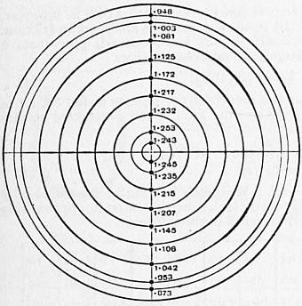
Fig. 84.
§ 79. Influence of Temperature on the Flow through Pipes.—Very careful experiments on the flow through a pipe 0.1236 ft. in diameter and 25 ft. long, with water at different temperatures, have been made by J. G. Mair (Proc. Inst. Civ. Eng. lxxxiv.). The loss of head was measured from a point 1 ft. from the inlet, so that the loss at entry was eliminated. The 11⁄2 in. pipe was made smooth inside and to gauge, by drawing a mandril through it. Plotting the results logarithmically, it was found that the resistance for all temperatures varied very exactly as v1.795, the index being less than 2 as in other experiments with very smooth surfaces. Taking the ordinary equation of flow h = ζ (4L/D) (v2/2g), then for heads varying from 1 ft. to nearly 4 ft., and velocities in the pipe varying from 4 ft. to 9 ft. per second, the values of ζ were as follows:—
Temp. F. ζ Temp. F. ζ
57 .0044 to .0052 100 .0039 to .0042
70 .0042 to .0045 110 .0037 to .0041
80 .0041 to .0045 120 .0037 to .0041
90 .0040 to .0045 130 .0035 to .0039
160 .0035 to .0038
This shows a marked decrease of resistance as the temperature rises. If Professor Osborne Reynolds’s equation is assumed h = mLVn/d3−n, and n is taken 1.795, then values of m at each temperature are practically constant—
Temp. F. m. Temp. F. m.
57 0.000276 100 0.000244
70 0.000263 110 0.000235
80 0.000257 120 0.000229
90 0.000250 130 0.000225
160 0.000206
where again a regular decrease of the coefficient occurs as the temperature rises. In experiments on the friction of disks at different temperatures Professor W. C. Unwin found that the resistance was proportional to constant × (1 − 0.0021t) and the values of m given above are expressed almost exactly by the relation
m = 0.000311 (1 − 0.00215 t).
In tank experiments on ship models for small ordinary variations of temperature, it is usual to allow a decrease of 3% of resistance for 10° F. increase of temperature.
§ 80. Influence of Deposits in Pipes on the Discharge. Scraping Water Mains.—The influence of the condition of the surface of a pipe on the friction is shown by various facts known to the engineers of waterworks. In pipes which convey certain kinds of water, oxidation proceeds rapidly and the discharge is considerably diminished. A main laid at Torquay in 1858, 14 m. in length, consists of 10-in., 9-in. and 8-in. pipes. It was not protected from corrosion by any coating. But it was found to the surprise of the engineer that in eight years the discharge had diminished to 51% of the original discharge. J. G. Appold suggested an apparatus for scraping the interior of the pipe, and this was constructed and used under the direction of William Froude (see “Incrustation of Iron Pipes,” by W. Ingham, Proc. Inst. Mech. Eng., 1899). It was found that by scraping the interior of the pipe the discharge was increased 56%. The scraping requires to be repeated at intervals. After each scraping the discharge diminishes rather rapidly to 10% and afterwards more slowly, the diminution in a year being about 25%.
Fig. 85 shows a scraper for water mains, similar to Appold’s but modified in details, as constructed by the Glenfield Company, at Kilmarnock. A is a longitudinal section of the pipe, showing the scraper in place; B is an end view of the plungers, and C, D sections of the boxes placed at intervals on the main for introducing or withdrawing the scraper. The apparatus consists of two plungers, packed with leather so as to fit the main pretty closely. On the spindle of these plungers are fixed eight steel scraping blades, with curved scraping edges fitting the surface of the main. The apparatus is placed in the main by removing the cover from one of the boxes shown at C, D. The cover is then replaced, water pressure is admitted behind the plungers, and the apparatus driven through the main. At Lancaster after twice scraping the discharge was increased 561⁄2%, at Oswestry 541⁄2%. The increased discharge is due to the diminution of the friction of the pipe by removing the roughnesses due to oxidation. The scraper can be easily followed when the mains are about 3 ft. deep by the noise it makes. The average speed of the scraper at Torquay is 21⁄3 m. per hour. At Torquay 49% of the deposit is iron rust, the rest being silica, lime and organic matter.
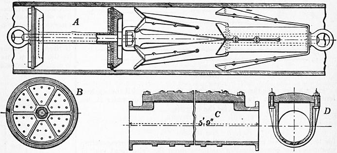
Fig. 85. Scale 1⁄25.
In the opinion of some engineers it is inadvisable to use the scraper. The incrustation is only temporarily removed, and if the use of the scraper is continued the life of the pipe is reduced. The only treatment effective in preventing or retarding the incrustation due to corrosion is to coat the pipes when hot with a smooth and perfect layer of pitch. With certain waters such as those derived from the chalk the incrustation is of a different character, consisting of nearly pure calcium carbonate. A deposit of another character which has led to trouble in some mains is a black slime containing a good deal of iron not derived from the pipes. It appears to be an organic growth. Filtration of the water appears to prevent the growth of the slime, and its temporary removal may be effected by a kind of brush scraper devised by G. F. Deacon (see “Deposits in Pipes,” by Professor J. C. Campbell Brown, Proc. Inst. Civ. Eng., 1903-1904).
§ 81. Flow of Water through Fire Hose.—The hose pipes used for fire purposes are of very varied character, and the roughness of the surface varies. Very careful experiments have been made by J. R. Freeman (Am. Soc. Civ. Eng. xxi., 1889). It was noted that under pressure the diameter of the hose increased sufficiently to have a marked influence on the discharge. In reducing the results the true diameter has been taken. Let v = mean velocity in ft. per sec.; r = hydraulic mean radius or one-fourth the diameter in feet; i = hydraulic gradient. Then v = n √(ri).
Diameter in Inches. Gallons (United States) per min. i v n
Solid rubber hose 2.65 215 .1863 12.50 123.3
” 344 .4714 20.00 124.0
Woven cotton, rubber lined 2.47 200 .2464 13.40 119.1
” 299 .5269 20.00 121.5
Woven cotton, rubber lined 2.49 200 .2427 13.20 117.7
” 319 .5708 21.00 122.1
Knit cotton, rubber lined 2.68 132 .0809 7.50 111.6
” 299 .3931 17.00 114.8
Knit cotton, rubber lined 2.69 204 .2357 11.50 100.1
” 319 .5165 18.00 105.8
Woven cotton, rubber lined 2.12 154 .3448 14.00 113.4
” 240 .7673 21.81 118.4
Woven cotton, rubber lined 2.53 54.8 .0261 3.50 94.3
” 298 .8264 19.00 91.0
Unlined linen hose 2.60 57.9 .0414 3.50 73.9
” 331 1.1624 20.00 79.6
§ 82. Reduction of a Long Pipe of Varying Diameter to an Equivalent Pipe of Uniform Diameter. Dupuit’s Equation.—Water mains for the supply of towns often consist of a series of lengths, the diameter being the same for each length, but differing from length to length. In approximate calculations of the head lost in such mains, it is generally accurate enough to neglect the smaller losses of head and to have regard to the pipe friction only, and then the calculations may be facilitated by reducing the main to a main of uniform diameter, in which there would be the same loss of head. Such a uniform main will be termed an equivalent main.
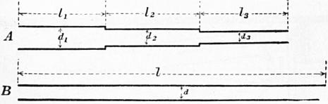
Fig. 86.
In fig. 86 let A be the main of variable diameter, and B the equivalent uniform main. In the given main of variable diameter A, let
l1, l2 be the lengths,
d1, d2 the diameters,
v1, v2 the velocities,
i1, i2 the slopes,
for the successive portions, and let l, d, v and i be corresponding quantities for the equivalent uniform main B. The total loss of head in A due to friction is
h = i1l1 + i2l2 + ... = ζ (v12 · 4l1/2gd1) + ζ (v22 · 4l2/2gd2) + ...
and in the uniform main
il = ζ (v2 · 4l/2gd).
If the mains are equivalent, as defined above,
ζ (v2 · 4l/2gd) = ζ (v12 · 4l1/2gd1) + ζ (v22 · 4l2/2gd2) + ...
But, since the discharge is the same for all portions,
1⁄4πd2v = 1⁄4πd12v1 = 1⁄4πd22v2 = ... v1 = vd2/d12; v2 = vd2/d22 ...
Also suppose that ζ may be treated as constant for all the pipes. Then
l/d = (d4/d14) (l1/d1) + (d4/d24) (l2/d2) + ... l = (d5/d15) l1 + (d5/d25) l2 + ...
which gives the length of the equivalent uniform main which would have the same total loss of head for any given discharge.
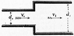
Fig. 87.
§ 83. Other Losses of Head in Pipes.—Most of the losses of head in pipes, other than that due to surface friction against the pipe, are due to abrupt changes in the velocity of the stream producing eddies. The kinetic energy of these is deducted from the general energy of translation, and practically wasted.
Sudden Enlargement of Section.—Suppose a pipe enlarges in section from an area ω0 to an area ω1 (fig. 87); then
v1/v0 = ω0/ω1;
or, if the section is circular,
v1/v0 = (d0/d1)2.
The head lost at the abrupt change of velocity has already been shown to be the head due to the relative velocity of the two parts of the stream. Hence head lost
ɧe = (v0 − v1)2/2g = (ω1/ω0 − 1)2 v12/2g = {(d1/d0)2 − 1}2 v12/2g
or
ɧe = ζev12/2g,
(1)
if ζe is put for the expression in brackets.
ω1/ω0 = 1.1 1.2 1.5 1.7 1.8 1.9 2.0 2.5 3.0 3.5 4.0 5.0 6.0 7.0 8.0
d1/d0 = 1.05 1.10 1.22 1.30 1.34 1.38 1.41 1.58 1.73 1.87 2.00 2.24 2.45 2.65 2.83
ζe = .01 .04 .25 .49 .64 .81 1.00 2.25 4.00 6.25 9.00 16.00 25.00 36.0 49.0
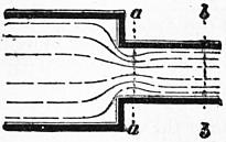
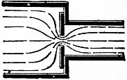
Fig. 88. Fig. 89.
Abrupt Contraction of Section.—When water passes from a larger to a smaller section, as in figs. 88, 89, a contraction is formed, and the contracted stream abruptly expands to fill the section of the pipe. Let ω be the section and v the velocity of the stream at bb. At aa the section will be ccω, and the velocity (ω/ccω) v = v/c1, where cc is the coefficient of contraction. Then the head lost is
ɧm = (v/cc − v)2 / 2g = (1/cc − 1)2 v2/2g;
and, if cc is taken 0.64,
ɧm = 0.316 v2/2g.
(2)
The value of the coefficient of contraction for this case is, however, not well ascertained, and the result is somewhat modified by friction. For water entering a cylindrical, not bell-mouthed, pipe from a reservoir of indefinitely large size, experiment gives
ɧa = 0.505 v2/2g.
(3)
If there is a diaphragm at the mouth of the pipe as in fig. 89, let ω1 be the area of this orifice. Then the area of the contracted stream is ccω1, and the head lost is
ɧc = {(ω/ccω1) − 1}2 v2/2g = ζcv2 / 2g
(4)
if ζ, is put for {(ω/ccω1) − 1}2. Weisbach has found experimentally the following values of the coefficient, when the stream approaching the orifice was considerably larger than the orifice:—
ω1/ω = 0.1 0.2 0.3 0.4 0.5 0.6 0.7 0.8 0.9 1.0
cc = .616 .614 .612 .610 .617 .605 .603 .601 .598 .596
ζc = 231.7 50.99 19.78 9.612 5.256 3.077 1.876 1.169 0.734 0.480

Fig. 90.
When a diaphragm was placed in a tube of uniform section (fig. 90) the following values were obtained, ω1 being the area of the orifice and ω that of the pipe:—
ω1/ω = 0.1 0.2 0.3 0.4 0.5 0.6 0.7 0.8 0.9 1.0
ce = .624 .632 .643 .659 .681 .712 .755 .813 .892 1.00
ξc = 225.9 47.77 30.83 7.801 1.753 1.796 .797 .290 .060 .000
Elbows.—Weisbach considers the loss of head at elbows (fig. 91) to be due to a contraction formed by the stream. From experiments with a pipe 11⁄4 in. diameter, he found the loss of head
ɧe = ζεv2 / 2g;
(5)
ζe = 0.9457 sin2 1⁄2φ + 2.047 sin4 1⁄2φ.
φ = 20° 40° 60° 80° 90° 100° 110° 120° 130° 140°
ζε = 0.046 0.139 0.364 0.740 0.984 1.260 1.556 1.861 2.158 2.431
Hence at a right-angled elbow the whole head due to the velocity very nearly is lost.
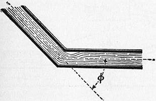
Fig. 91.
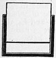
Fig. 92.
Bends.—Weisbach traces the loss of head at curved bends to a similar cause to that at elbows, but the coefficients for bends are not very satisfactorily ascertained. Weisbach obtained for the loss of head at a bend in a pipe of circular section
ɧb = ζbv2 / 2g;
(6)
ζb = 0.131 + 1.847 (d/2ρ)7/2,
where d is the diameter of the pipe and ρ the radius of curvature of the bend. The resistance at bends is small and at present very ill determined.
Valves, Cocks and Sluices.—These produce a contraction of the water-stream, similar to that for an abrupt diminution of section already discussed. The loss of head may be taken as before to be
ɧv = ζvv2 / 2g;
(7)
where v is the velocity in the pipe beyond the valve and ζv a coefficient determined by experiment. The following are Weisbach’s results.
Sluice in Pipe of Rectangular Section (fig. 92). Section at sluice = ω1 in pipe = ω.
ω1/ω = 1.0 0.9 0.8 0.7 0.6 0.5 0.4 0.3 0.2 0.1
ζv = 0.00 .09 .39 .95 2.08 4.02 8.12 17.8 44.5 193
Sluice in Cylindrical Pipe (fig. 93).
Ratio of height of opening to diameter of pipe 1.0 7⁄8 3⁄4 5⁄8 1⁄2 3⁄8 1⁄4 1⁄5
ω1/ω = 1.00 0.948 .856 .740 .609 .466 .315 .159
ζv = 0.00 0.07 0.26 0.81 2.06 5.52 17.0 97.8
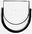
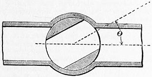
Fig. 93. Fig. 94.
Cock in a Cylindrical Pipe (fig. 94). Angle through which cock is turned = θ.
θ = 5° 10° 15° 20° 25° 30° 35°
Ratio of cross sections .926 .850 .772 .692 .613 .535 .458
ζv = .05 .29 .75 1.56 3.10 5.47 9.68
θ = 40° 45° 50° 55° 60° 65° 82°
Ratio of cross sections .385 .315 .250 .190 .137 .091 0
ζv = 17.3 31.2 52.6 106 206 486 ∞
Throttle Valve in a Cylindrical Pipe (fig. 95)
θ = 5° 10° 15° 20° 25° 30° 35° 40°
ζv = .24 .52 .90 1.54 2.51 3.91 6.22 10.8
θ = 45° 50° 55° 60° 65° 70° 90°
ζv = 18.7 32.6 58.8 118 256 751 ∞
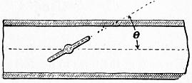
Fig. 95.
§ 84. Practical Calculations on the Flow of Water in Pipes.—In the following explanations it will be assumed that the pipe is of so great a length that only the loss of head in friction against the surface of the pipe needs to be considered. In general it is one of the four quantities d, i, v or Q which requires to be determined. For since the loss of head h is given by the relation h = il, this need not be separately considered.
There are then three equations (see eq. 4, § 72, and 9a, § 76) for the solution of such problems as arise:—
ζ = α (1 + 1/12d);
(1)
where α = 0.005 for new and = 0.01 for incrusted pipes.
ζv2 / 2g = 1⁄4di.
(2)
Q = 1⁄4πd2v.
(3)
Problem 1. Given the diameter of the pipe and its virtual slope, to find the discharge and velocity of flow. Here d and i are given, and Q and v are required. Find ζ from (1); then v from (2); lastly Q from (3). This case presents no difficulty.
By combining equations (1) and (2), v is obtained directly:—
v = √ (gdi/2ζ) = √ (g/2α) √ [di / {1 + 1/12d}].
(4)
For new pipes √ (g/2α) = 56.72
For incrusted pipes = 40.13
For pipes not less than 1, or more than 4 ft. in diameter, the mean values of ζ are
For new pipes 0.00526
For incrusted pipes 0.01052.
Using these values we get the very simple expressions—
v = 55.31 √ (di) for new pipes = 39.11 √ (di) for incrusted pipes.
(4a)
Within the limits stated, these are accurate enough for practical purposes, especially as the precise value of the coefficient ζ cannot be known for each special case.
Problem 2. Given the diameter of a pipe and the velocity of flow, to find the virtual slope and discharge. The discharge is given by (3); the proper value of ζ by (1); and the virtual slope by (2). This also presents no special difficulty.
Problem 3. Given the diameter of the pipe and the discharge, to find the virtual slope and velocity. Find v from (3); ζ from (1); lastly i from (2). If we combine (1) and (2) we get
i = ζ (v2/2g) (4/d) = 2a {1 + 1/12d} v2/gd;
(5)
and, taking the mean values of ζ for pipes from 1 to 4 ft. diameter, given above, the approximate formulae are
i = 0.0003268 v2/d for new pipes = 0.0006536 v2/d for incrusted pipes.
(5a)
Problem 4. Given the virtual slope and the velocity, to find the diameter of the pipe and the discharge. The diameter is obtained from equations (2) and (1), which give the quadratic expression
d2 − d (2αv2/gi) − αv2/6gi = 0.
∴ d = αv2/gi + √ {(αv2/gi) (αv2/gi + 1/6)}.
(6)
For practical purposes, the approximate equations
d = 2αv2/gi + 1/12 = 0.00031 v2/i + .083 for new pipes = 0.00062 v2/i + .083 for incrusted pipes
(6a)
are sufficiently accurate.
Problem 5. Given the virtual slope and the discharge, to find the diameter of the pipe and velocity of flow. This case, which often occurs in designing, is the one which is least easy of direct solution. From equations (2) and (3) we get—
d5 = 32ζQ2 / gπ2i.
(7)
If now the value of ζ in (1) is introduced, the equation becomes very cumbrous. Various approximate methods of meeting the difficulty may be used.
(a) Taking the mean values of ζ given above for pipes of 1 to 4 ft. diameter we get
d = 5√ (32ζ/gπ2) 5√ (Q2/i) = 0.2216 5√ (Q2/i) for new pipes = 0.2541 5√ (Q2/i) for incrusted pipes;
(8)
equations which are interesting as showing that when the value of ζ is doubled the diameter of pipe for a given discharge is only increased by 13%.
(b) A second method is to obtain a rough value of d by assuming ζ = α. This value is
d′ = 5√ (32Q2 / gπ2i) 5√ α = 0.6319 5√ (Q2/i) 5√ α.
Then a very approximate value of ζ is
ζ′ = α (1 + 1/12d′);
and a revised value of d, not sensibly differing from the exact value, is
d″ = 5√ (32Q2 / gπ2i) 5√ ζ′ = 0.6319 5√ (Q2/i) 5√ ζ′.
(c) Equation 7 may be put in the form
d = 5√ (32αQ2 / gπ2i) 5√ (1 + 1/12d).
(9)
Expanding the term in brackets,
5√ (1 + 1/12d) = 1 + 1/60d − 1/1800d2 ...
Neglecting the terms after the second,
d = 5√ (32α / gπ2) 5√ (Q2/i) · {1 + 1/60d} = 5√ (32α / gπ2) 5√ (Q2/i) + 0.01667;
(9a)
and
5√ (32α / gπ2) = 0.219 for new pipes = 0.252 for incrusted pipes.
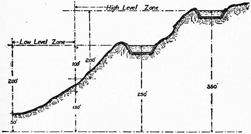
Fig. 96.
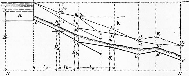
Fig. 97.
§ 85. Arrangement of Water Mains for Towns’ Supply.—Town mains are usually supplied oy gravitation from a service reservoir, which in turn is supplied by gravitation from a storage reservoir or by pumping from a lower level. The service reservoir should contain three days’ supply or in important cases much more. Its elevation should be such that water is delivered at a pressure of at least about 100 ft. to the highest parts of the district. The greatest pressure in the mains is usually about 200 ft., the pressure for which ordinary pipes and fittings are designed. Hence if the district supplied has great variations of level it must be divided into zones of higher and lower pressure. Fig. 96 shows a district of two zones each with its service reservoir and a range of pressure in the lower district from 100 to 200 ft. The total supply required is in England about 25 gallons per head per day. But in many towns, and especially in America, the supply is considerably greater, but also in many cases a good deal of the supply is lost by leakage of the mains. The supply through the branch mains of a distributing system is calculated from the population supplied. But in determining the capacity of the mains the fluctuation of the demand must be allowed for. It is usual to take the maximum demand at twice the average demand. Hence if the average demand is 25 gallons per head per day, the mains should be calculated for 50 gallons per head per day.
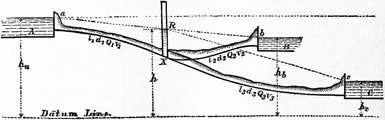
Fig. 98.
§ 86. Determination of the Diameters of Different Parts of a Water Main.—When the plan of the arrangement of mains is determined upon, and the supply to each locality and the pressure required is ascertained, it remains to determine the diameters of the pipes. Let fig. 97 show an elevation of a main ABCD ..., R being the reservoir from which the supply is derived. Let NN be the datum line of the levelling operations, and Ha, Hb ... the heights of the main above the datum line, Hr being the height of the water surface in the reservoir from the same datum. Set up next heights AA1, BB1, ... representing the minimum pressure height necessary for the adequate supply of each locality. Then A1B1C1D1 ... is a line which should form a lower limit to the line of virtual slope. Then if heights ɧa, ɧb, ɧc ... are taken representing the actual losses of head in each length la, lb, lc ... of the main, A0B0C0 will be the line of virtual slope, and it will be obvious at what points such as D0 and E0, the pressure is deficient, and a different choice of diameter of main is required. For any point z in the length of the main, we have
Pressure height = Hr − Hz − (ɧa + ɧb + ... ɧz).
Where no other circumstance limits the loss of head to be assigned to a given length of main, a consideration of the safety of the main from fracture by hydraulic shock leads to a limitation of the velocity of flow. Generally the velocity in water mains lies between 11⁄2 and 41⁄2 ft. per second. Occasionally the velocity in pipes reaches 10 ft. per second, and in hydraulic machinery working under enormous pressures even 20 ft. per second. Usually the velocity diminishes along the main as the discharge diminishes, so as to reduce somewhat the total loss of head which is liable to render the pressure insufficient at the end of the main.
J. T. Fanning gives the following velocities as suitable in pipes for towns’ supply:—
Diameter in inches 4 8 12 18 24 30 36
Velocity in feet per sec. 2.5 3.0 3.5 4.5 5.3 6.2 7.0
§ 87. Branched Pipe connecting Reservoirs at Different Levels.—Let A, B, C (fig. 98) be three reservoirs connected by the arrangement of pipes shown,—l1, d1, Q1, v1; l2, d2, Q2, v2; h3, d3, Q3, v3 being the length, diameter, discharge and velocity in the three portions of the main pipe. Suppose the dimensions and positions of the pipes known and the discharges required.
If a pressure column is introduced at X, the water will rise to a height XR, measuring the pressure at X, and aR, Rb, Rc will be the lines of virtual slope. If the free surface level at R is above b, the reservoir A supplies B and C, and if R is below b, A and B supply C. Consequently there are three cases:—
I. R above b; Q1 = Q2 + Q3.
II. R level with b; Q1 = Q3; Q2 = 0
III. R below b; Q1 + Q2 = Q3.
To determine which case has to be dealt with in the given conditions, suppose the pipe from X to B closed by a sluice. Then there is a simple main, and the height of free surface h′ at X can be determined. For this condition
ha − h′ = ζ (v12/2g) (4l1/d1) = 32ζQ′2l1 / gπ2d15;
h′ − hc = ζ (v32/2g) (4l3/d3) = 32ζQ′2l3 / gπ2d35;
where Q′ is the common discharge of the two portions of the pipe. Hence
(ha − h′) / (h′ − hc) = l1d35 / l3d15,
from which h′ is easily obtained. If then h′ is greater than hb, opening the sluice between X and B will allow flow towards B, and the case in hand is case I. If h′ is less than hb, opening the sluice will allow flow from B, and the case is case III. If h′ = hb, the case is case II., and is already completely solved.
The true value of h must lie between h′ and hb. Choose a new value of h, and recalculate Q1, Q2, Q3. Then if
Q1 > Q2 + Q3 in case I.,
or
Q1 + Q2 > Q3 in case III.,
the value chosen for h is too small, and a new value must be chosen.
If
Q1 < Q2 + Q3 in case I.,
or
Q1 + Q2 < Q3 in case III.,
the value of h is too great.
Since the limits between which h can vary are in practical cases not very distant, it is easy to approximate to values sufficiently accurate.
§ 88. Water Hammer.—If in a pipe through which water is flowing a sluice is suddenly closed so as to arrest the forward movement of the water, there is a rise of pressure which in some cases is serious enough to burst the pipe. This action is termed water hammer or water ram. The fluctuation of pressure is an oscillating one and gradually dies out. Care is usually taken that sluices should only be closed gradually and then the effect is inappreciable. Very careful experiments on water hammer were made by N. J. Joukowsky at Moscow in 1898 (Stoss in Wasserleitungen, St Petersburg, 1900), and the results are generally confirmed by experiments made by E. B. Weston and R. C. Carpenter in America. Joukowsky used pipes, 2, 4 and 6 in. diameter, from 1000 to 2500 ft. in length. The sluice closed in 0.03 second, and the fluctuations of pressure were automatically registered. The maximum excess pressure due to water-hammer action was as follows:—
Pipe 4-in. diameter. Pipe 6-in. diameter.
Velocity ft. per sec. Excess Pressure. ℔ per sq. in. Velocity ft. per sec. Excess Pressure. ℔ per sq. in.
0.5 31 0.6 43
2.9 168 3.0 173
4.1 232 5.6 369
9.2 519 7.5 426
In some cases, in fixing the thickness of water mains, 100 ℔ per sq. in. excess pressure is allowed to cover the effect of water hammer. With the velocities usual in water mains, especially as no valves can be quite suddenly closed, this appears to be a reasonable allowance (see also Carpenter, Am. Soc. Mech. Eng., 1893).
IX. FLOW OF COMPRESSIBLE FLUIDS IN PIPES
§ 89. Flow of Air in Long Pipes.—When air flows through a long pipe, by far the greater part of the work expended is used in overcoming frictional resistances due to the surface of the pipe. The work expended in friction generates heat, which for the most part must be developed in and given back to the air. Some heat may be transmitted through the sides of the pipe to surrounding materials, but in experiments hitherto made the amount so conducted away appears to be very small, and if no heat is transmitted the air in the tube must remain sensibly at the same temperature during expansion. In other words, the expansion may be regarded as isothermal expansion, the heat generated by friction exactly neutralizing the cooling due to the work done. Experiments on the pneumatic tubes used for the transmission of messages, by R. S. Culley and R. Sabine (Proc. Inst. Civ. Eng. xliii.), show that the change of temperature of the air flowing along the tube is much less than it would be in adiabatic expansion.
§ 90. Differential Equation of the Steady Motion of Air Flowing in a Long Pipe of Uniform Section.—When air expands at a constant absolute temperature τ, the relation between the pressure p in pounds per square foot and the density or weight per cubic foot G is given by the equation
p/G = cτ,
(1)
where c = 53.15. Taking τ = 521, corresponding to a temperature of 60° Fahr.,
cτ = 27690 foot-pounds.
(2)
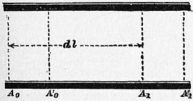
Fig. 99.
The equation of continuity, which expresses the condition that in steady motion the same weight of fluid, W, must pass through each cross section of the stream in the unit of time, is
GΩu = W = constant,
(3)
where Ω is the section of the pipe and u the velocity of the air. Combining (1) and (3),
Ωup/W = cτ = constant.
(3a)
Since the work done by gravity on the air during its flow through a pipe due to variations of its level is generally small compared with the work done by changes of pressure, the former may in many cases be neglected.
Consider a short length dl of the pipe limited by sections A0, A1 at a distance dl (fig. 99). Let p, u be the pressure and velocity at A0, p + dp and u + du those at A1. Further, suppose that in a very short time dt the mass of air between A0A1 comes to A′0A′1 so that A0A′0 = udt and A1A′1 = (u + du) dt1. Let Ω be the section, and m the hydraulic mean radius of the pipe, and W the weight of air flowing through the pipe per second.
From the steadiness of the motion the weight of air between the sections A0A′0, and A1A′1 is the same. That is,
W dt = GΩu dt = GΩ (u + du) dt.
By analogy with liquids the head lost in friction is, for the length dl (see § 72, eq. 3), ζ (u2/2g) (dl/m). Let H = u2/2g. Then the head lost is ζ(H/m)dl; and, since Wdt ℔ of air flow through the pipe in the time considered, the work expended in friction is −ζ (H/m)W dl dt. The change of kinetic energy in dt seconds is the difference of the kinetic energy of A0A′0 and A1A′1, that is,
(W/g) dt {(u + du)2 − u2} / 2 = (W/g) u du dt = W dH dt.
The work of expansion when Ωudt cub. ft. of air at a pressure p expand to Ω(u + du) dt cub. ft. is Ωp du dt. But from (3a) u = cτW/Ωp, and therefore
du / dp = −cτW / Ωp2.
And the work done by expansion is −(cτW/p) dp dt.
The work done by gravity on the mass between A0 and A1 is zero if the pipe is horizontal, and may in other cases be neglected without great error. The work of the pressures at the sections A0A1 is
pΩu dt − (p + dp) Ω (u + du) dt = −(p du + u dp) Ω dt
But from (3a)
pu = constant, p du + u dp = 0,
and the work of the pressures is zero. Adding together the quantities of work, and equating them to the change of kinetic energy,
W dH dt = −(cτW/p) dp dt − ζ (H/m) W dl dt dH + (cτ/p) dp + ζ (H/m) dl = 0, dH/H + (cτ/Hp) dp + ζdl / m = 0
(4)
But
u = cτW / Ωp,
and
H = u2/2g = c2τ2W2 / 2gΩ2p2,
∴ dH/H + (2gΩ2p / cτW2) dp + ζdl / m = 0.
(4a)
For tubes of uniform section m is constant; for steady motion W is constant; and for isothermal expansion τ is constant. Integrating,
log H + gΩ2p2 / W2cτ + ζ l / m = constant;
(5)
for
l = 0, let H = H0, and p = p0;
and for
l = l, let H = H1, and p = p1.
log (H1/H0) + (gΩ2 / W2cτ) (p12 − p02) + ζ l / m = 0.
(5a)
where p0 is the greater pressure and p1 the less, and the flow is from A0 towards A1.
By replacing W and H,
log (p0/p1) + (gcτ / u02p02) (p12 − p02 + ζ l/m = 0
(6)
Hence the initial velocity in the pipe is
u0 = √ [{gcτ (p02 − p12)} / {p02 (ζ l/m + log (p0 / p1) }].
(7)
When l is great, log p0/p1 is comparatively small, and then
u0 = √ [ (gcτm/ζ l) {(p02 − p12) / p02} ],
(7a)
a very simple and easily used expression. For pipes of circular section m = d/4, where d is the diameter:—
u0 = √ [ (gcτd / 4ζ l) {(p02 − p12) / p02} ];
(7b)
or approximately
u0 = (1.1319 − 0.7264 p1/p0) √ (gcτd / 4ζ l).
(7c)
§ 91. Coefficient of Friction for Air.—A discussion by Professor Unwin of the experiments by Culley and Sabine on the rate of transmission of light carriers through pneumatic tubes, in which there is steady flow of air not sensibly affected by any resistances other than surface friction, furnished the value ζ = .007. The pipes were lead pipes, slightly moist, 21⁄4 in. (0.187 ft.) in diameter, and in lengths of 2000 to nearly 6000 ft.
In some experiments on the flow of air through cast-iron pipes A. Arson found the coefficient of friction to vary with the velocity and diameter of the pipe. Putting
ζ = α/v + β,
(8)
he obtained the following values—
Diameter of Pipe in feet. α β ζ for 100 ft. per second.
1.64 .00129 .00483 .00484
1.07 .00972 .00640 .00650
.83 .01525 .00704 .00719
.338 .03604 .00941 .00977
.266 .03790 .00959 .00997
.164 .04518 .01167 .01212
It is worth while to try if these numbers can be expressed in the form proposed by Darcy for water. For a velocity of 100 ft. per second, and without much error for higher velocities, these numbers agree fairly with the formula
ζ = 0.005 (1 + 3/10d),
(9)
which only differs from Darcy’s value for water in that the second term, which is always small except for very small pipes, is larger.
Some later experiments on a very large scale, by E. Stockalper at the St Gotthard Tunnel, agree better with the value
ζ = 0.0028 (1 + 3/10d).
These pipes were probably less rough than Arson’s.
When the variation of pressure is very small, it is no longer safe to neglect the variation of level of the pipe. For that case we may neglect the work done by expansion, and then
z0 − z1 − p0/G0 − p1/G1 − ζ (v2/2g) (l/m) = 0,
(10)
precisely equivalent to the equation for the flow of water, z0 and z1 being the elevations of the two ends of the pipe above any datum, p0 and p1 the pressures, G0 and G1 the densities, and v the mean velocity in the pipe. This equation may be used for the flow of coal gas.
§ 92. Distribution of Pressure in a Pipe in which Air is Flowing.—From equation (7a) it results that the pressure p, at l ft. from that end of the pipe where the pressure is p0, is
p = p0 √ (1 − ζ lu02 / mgcτ);
(11)
which is of the form
p = √ (al + b)
for any given pipe with given end pressures. The curve of free surface level for the pipe is, therefore, a parabola with horizontal axis. Fig. 100 shows calculated curves of pressure for two of Sabine’s experiments, in one of which the pressure was greater than atmospheric pressure, and in the other less than atmospheric pressure. The observed pressures are given in brackets and the calculated pressures without brackets. The pipe was the pneumatic tube between Fenchurch Street and the Central Station, 2818 yds. in length. The pressures are given in inches of mercury.
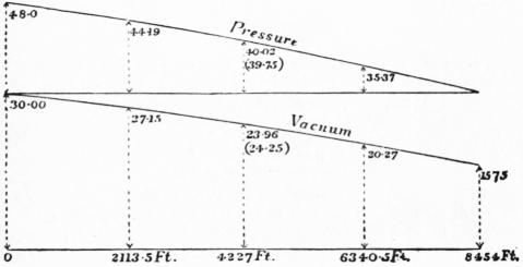
Fig. 100.
Variation of Velocity in the Pipe.—Let p0, u0 be the pressure and velocity at a given section of the pipe; p, u, the pressure and velocity at any other section. From equation (3a)
up = cτW / Ω = constant;
so that, for any given uniform pipe,
up = u0p0, u = u0p0 / p;
(12)
which gives the velocity at any section in terms of the pressure, which has already been determined. Fig. 101 gives the velocity curves for the two experiments of Culley and Sabine, for which the pressure curves have already been drawn. It will be seen that the velocity increases considerably towards that end of the pipe where the pressure is least.
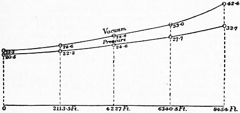
Fig. 101.
§ 93. Weight of Air Flowing per Second.—The weight of air discharged per second is (equation 3a)—
W = Ωu0p0 / cτ.
From equation (7b), for a pipe of circular section and diameter d,
W = 1⁄4π √ (gd5 (p02 − p12) / ζ lcτ), = .611 √ (d5 (p02 − p12) / ζ lτ).
(13)
Approximately
W = (.6916p0 − .4438p1) (d5 / ζ lτ)1/2.
(13a)
§ 94. Application to the Case of Pneumatic Tubes for the Transmission of Messages.—In Paris, Berlin, London, and other towns, it has been found cheaper to transmit messages in pneumatic tubes than to telegraph by electricity. The tubes are laid underground with easy curves; the messages are made into a roll and placed in a light felt carrier, the resistance of which in the tubes in London is only 3⁄4 oz. A current of air forced into the tube or drawn through it propels the carrier. In most systems the current of air is steady and continuous, and the carriers are introduced or removed without materially altering the flow of air.
Time of Transit through the Tube.—Putting t for the time of transit from 0 to l,
t = ∫l0 dl/u,
From (4a) neglecting dH/H, and putting m = d/4,
dl = gdΩ2p dp / 2ζW2cr.
From (1) and (3)
u = Wcτ / pΩ; dl/u = gdΩ3p2 dp / 2ζW3c2τ2;
t = ∫p0p1 g dΩ3 p2 dp / 2ζW3c2τ2, = g dΩ3 (p03 − p13) / 6ζW3c2τ2.
(14)
But
W = p0u0Ω / cτ;
∴ t = gdcτ (p03 − p13) / 6ζp03u03, = ζ1/2 l3/2 (p03 − p13) / 6(gcτd)1/2 (p02 − p12)3/2;
(15)
If τ = 521°, corresponding to 60° F.,
t = .001412 ζ1/2 l3/2 (p03 − p13) / d1/2 (p02 − p12)3/2;
(15a)
which gives the time of transmission in terms of the initial and final pressures and the dimensions of the tube.
Mean Velocity of Transmission.—The mean velocity is l/t; or, for τ = 521°,