VOLUME XIV SLICE I Husband to Hydrolysis (continued 5)
Reading edition
40 .6066 .6045 .6025 .6015 .6026 .6037 .6055 .6114
45 .6054 .6052 .6029 .6016 .6030 .6043 .6062 .6125
50 .6086 .6060 .6034 .6018 .6035 .6050 .6070 .6140
§ 21. Orifices with Edges of Sensible Thickness.—When the edges of the orifice are not bevelled outwards, but have a sensible thickness, the coefficient of discharge is somewhat altered. The following table gives values of the coefficient of discharge for the arrangements of the orifice shown in vertical section at P, Q, R (fig. 20). The plan of all the orifices is shown at S. The planks forming the orifice and sluice were each 2 in. thick, and the orifices were all 24 in. wide. The heads were measured immediately over the orifice. In this case,
Q = cb (H − h) √ { 2g(H + h)/2 }.
§ 22. Partially Suppressed Contraction.—Since the contraction of the jet is due to the convergence towards the orifice of the issuing streams, it will be diminished if for any portion of the edge of the orifice the convergence is prevented. Thus, if an internal rim or border is applied to part of the edge of the orifice (fig. 21), the convergence for so much of the edge is suppressed. For such cases G. Bidone found the following empirical formulae applicable:—
Table of Coefficients of Discharge for Rectangular Vertical Orifices in Fig. 20.
Head h above upper edge of Orifice in feet. Height of Orifice, H − h, in feet.
1.31 0.66 0.16 0.10
P Q R P Q R P Q R P Q R
0.328 0.598 0.644 0.648 0.634 0.665 0.668 0.691 0.664 0.666 0.710 0.694 0.696
.656 0.609 0.653 0.657 0.640 0.672 0.675 0.685 0.687 0.688 0.696 0.704 0.706
.787 0.612 0.655 0.659 0.641 0.674 0.677 0.684 0.690 0.692 0.694 0.706 0.708
.984 0.616 0.656 0.660 0.641 0.675 0.678 0.683 0.693 0.695 0.692 0.709 0.711
1.968 0.618 0.649 0.653 0.640 0.676 0.679 0.678 0.695 0.697 0.688 0.710 0.712
3.28 0.608 0.632 0.634 0.638 0.674 0.676 0.673 0.694 0.695 0.680 0.704 0.705
4.27 0.602 0.624 0.626 0.637 0.673 0.675 0.672 0.693 0.694 0.678 0.701 0.702
4.92 0.598 0.620 0.622 0.637 0.673 0.674 0.672 0.692 0.693 0.676 0.699 0.699
5.58 0.596 0.618 0.620 0.637 0.672 0.673 0.672 0.692 0.693 0.676 0.698 0.698
6.56 0.595 0.615 0.617 0.636 0.671 0.672 0.671 0.691 0.692 0.675 0.696 0.696
9.84 0.592 0.611 0.612 0.634 0.669 0.670 0.668 0.689 0.690 0.672 0.693 0.693
For rectangular orifices,
Cc = 0.62 (1 + 0.152 n/p);
and for circular orifices,
Cc = 0.62 (1 + 0.128 n/p);
when n is the length of the edge of the orifice over which the border extends, and p is the whole length of edge or perimeter of the orifice. The following are the values of cc, when the border extends over 1⁄4, 1⁄2, or 3⁄4 of the whole perimeter:—
n/p Cc Rectangular Orifices Cc Circular Orifices
0.25 0.643 .640
0.50 0.667 .660
0.75 0.691 .680
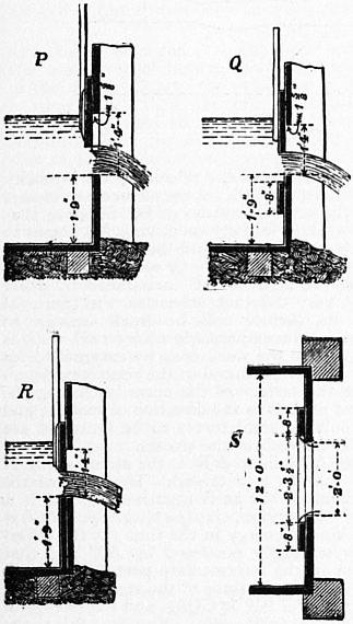
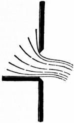
Fig. 20. Fig. 21.
For larger values of n/p the formulae are not applicable. C. R. Bornemann has shown, however, that these formulae for suppressed contraction are not reliable.
§ 23. Imperfect Contraction.—If the sides of the vessel approach near to the edge of the orifice, they interfere with the convergence of the streams to which the contraction is due, and the contraction is then modified. It is generally stated that the influence of the sides begins to be felt if their distance from the edge of the orifice is less than 2.7 times the corresponding width of the orifice. The coefficients of contraction for this case are imperfectly known.
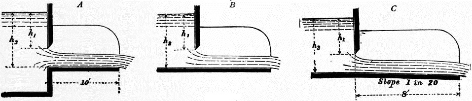
Fig. 22.
§ 24. Orifices Furnished with Channels of Discharge.—These external borders to an orifice also modify the contraction.
The following coefficients of discharge were obtained with openings 8 in. wide, and small in proportion to the channel of approach (fig. 22, A, B, C).
h2 − h1 in feet h1 in feet.
.0656 .164 .328 .656 1.640 3.28 4.92 6.56 9.84
A 0.656 .480 .511 .542 .574 .599 .601 .601 .601 .601
B .480 .510 .538 .506 .592 .600 .602 .602 .601
C .527 .553 .574 .592 .607 .610 .610 .609 .608
A 0.164 .488 .577 .624 .631 .625 .624 .619 .613 .606
B .487 .571 .606 .617 .626 .628 .627 .623 .618
C .585 .614 .633 .645 .652 .651 .650 .650 .649
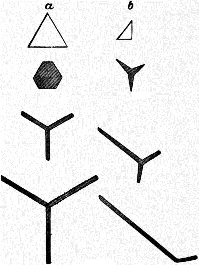
Fig. 23.
§ 25. Inversion of the Jet.—When a jet issues from a horizontal orifice, or is of small size compared with the head, it presents no marked peculiarity of form. But if the orifice is in a vertical surface, and if its dimensions are not small compared with the head, it undergoes a series of singular changes of form after leaving the orifice. These were first investigated by G. Bidone (1781-1839); subsequently H. G. Magnus (1802-1870) measured jets from different orifices; and later Lord Rayleigh (Proc. Roy. Soc. xxix. 71) investigated them anew.
Fig. 23 shows some forms, the upper figure giving the shape of the orifices, and the others sections of the jet. The jet first contracts as described above, in consequence of the convergence of the fluid streams within the vessel, retaining, however, a form similar to that of the orifice. Afterwards it expands into sheets in planes perpendicular to the sides of the orifice. Thus the jet from a triangular orifice expands into three sheets, in planes bisecting at right angles the three sides of the triangle. Generally a jet from an orifice, in the form of a regular polygon of n sides, forms n sheets in planes perpendicular to the sides of the polygon.
Bidone explains this by reference to the simpler case of meeting streams. If two equal streams having the same axis, but moving in opposite directions, meet, they spread out into a thin disk normal to the common axis of the streams. If the directions of two streams intersect obliquely they spread into a symmetrical sheet perpendicular to the plane of the streams.
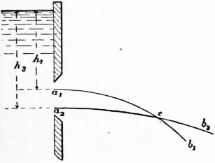
Fig. 24.
Let a1, a2 (fig. 24) be two points in an orifice at depths h1, h2 from the free surface. The filaments issuing at a1, a2 will have the different velocities √ 2gh1 and √ 2gh2. Consequently they will tend to describe parabolic paths a1cb1 and a2cb2 of different horizontal range, and intersecting in the point c. But since two filaments cannot simultaneously flow through the same point, they must exercise mutual pressure, and will be deflected out of the paths they tend to describe. It is this mutual pressure which causes the expansion of the jet into sheets.
Lord Rayleigh pointed out that, when the orifices are small and the head is not great, the expansion of the sheets in directions perpendicular to the direction of flow reaches a limit. Sections taken at greater distance from the orifice show a contraction of the sheets until a compact form is reached similar to that at the first contraction. Beyond this point, if the jet retains its coherence, sheets are thrown out again, but in directions bisecting the angles between the previous sheets. Lord Rayleigh accepts an explanation of this contraction first suggested by H. Buff (1805-1878), namely, that it is due to surface tension.
§ 26. Influence of Temperature on Discharge of Orifices.—Professor VV. C. Unwin found (Phil. Mag., October 1878, p. 281) that for sharp-edged orifices temperature has a very small influence on the discharge. For an orifice 1 cm. in diameter with heads of about 1 to 11⁄2 ft. the coefficients were:—
Temperature F. C.
205° .594
62° .598
For a conoidal or bell-mouthed orifice 1 cm. diameter the effect of temperature was greater:—
Temperature F. C.
190° 0.987
130° 0.974
60° 0.942
an increase in velocity of discharge of 4% when the temperature increased 130°.
J. G. Mair repeated these experiments on a much larger scale (Proc. Inst. Civ. Eng. lxxxiv.). For a sharp-edged orifice 21⁄2 in. diameter, with a head of 1.75 ft., the coefficient was 0.604 at 57° and 0.607 at 179° F., a very small difference. With a conoidal orifice the coefficient was 0.961 at 55° and 0.98l at 170° F. The corresponding coefficients of resistance are 0.0828 and 0.0391, showing that the resistance decreases to about half at the higher temperature.
§ 27. Fire Hose Nozzles.—Experiments have been made by J. R. Freeman on the coefficient of discharge from smooth cone nozzles used for fire purposes. The coefficient was found to be 0.983 for 3⁄4-in. nozzle; 0.982 for 7⁄8 in.; 0.972 for 1 in.; 0.976 for 11⁄8 in.; and 0.971 for 11⁄4 in. The nozzles were fixed on a taper play-pipe, and the coefficient includes the resistance of this pipe (Amer. Soc. Civ. Eng. xxi., 1889). Other forms of nozzle were tried such as ring nozzles for which the coefficient was smaller.
IV. THEORY OF THE STEADY MOTION OF FLUIDS.
§ 28. The general equation of the steady motion of a fluid given under Hydrodynamics furnishes immediately three results as to the distribution of pressure in a stream which may here be assumed.
(a) If the motion is rectilinear and uniform, the variation of pressure is the same as in a fluid at rest. In a stream flowing in an open channel, for instance, when the effect of eddies produced by the roughness of the sides is neglected, the pressure at each point is simply the hydrostatic pressure due to the depth below the free surface.
(b) If the velocity of the fluid is very small, the distribution of pressure is approximately the same as in a fluid at rest.
(c) If the fluid molecules take precisely the accelerations which they would have if independent and submitted only to the external forces, the pressure is uniform. Thus in a jet falling freely in the air the pressure throughout any cross section is uniform and equal to the atmospheric pressure.
(d) In any bounded plane section traversed normally by streams which are rectilinear for a certain distance on either side of the section, the distribution of pressure is the same as in a fluid at rest.
Distribution of Energy in Incompressible Fluids.
§ 29. Application of the Principle of the Conservation of Energy to Cases of Stream Line Motion.—The external and internal work done on a mass is equal to the change of kinetic energy produced. In many hydraulic questions this principle is difficult to apply, because from the complicated nature of the motion produced it is difficult to estimate the total kinetic energy generated, and because in some cases the internal work done in overcoming frictional or viscous resistances cannot be ascertained; but in the case of stream line motion it furnishes a simple and important result known as Bernoulli’s theorem.
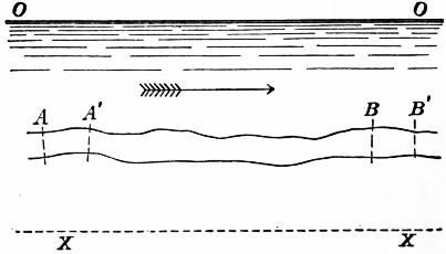
Fig. 25.
Let AB (fig. 25) be any one elementary stream, in a steadily moving fluid mass. Then, from the steadiness of the motion, AB is a fixed path in space through which a stream of fluid is constantly flowing. Let OO be the free surface and XX any horizontal datum line. Let ω be the area of a normal cross section, v the velocity, p the intensity of pressure, and z the elevation above XX, of the elementary stream AB at A, and ω1, p1, v1, z1 the same quantities at B. Suppose that in a short time t the mass of fluid initially occupying AB comes to A′B′. Then AA′, BB′ are equal to vt, v1t, and the volumes of fluid AA′, BB′ are the equal inflow and outflow = Qt = ωvt = ω1v1t, in the given time. If we suppose the filament AB surrounded by other filaments moving with not very different velocities, the frictional or viscous resistance on its surface will be small enough to be neglected, and if the fluid is incompressible no internal work is done in change of volume. Then the work done by external forces will be equal to the kinetic energy produced in the time considered.
The normal pressures on the surface of the mass (excluding the ends A, B) are at each point normal to the direction of motion, and do no work. Hence the only external forces to be reckoned are gravity and the pressures on the ends of the stream.
The work of gravity when AB falls to A′B′ is the same as that of transferring AA′ to BB′; that is, GQt (z − z1). The work of the pressures on the ends, reckoning that at B negative, because it is opposite to the direction of motion, is (pω × vt) − (p1ω1 × v1t) = Qt(p − p1). The change of kinetic energy in the time t is the difference of the kinetic energy originally possessed by AA′ and that finally acquired by BB′, for in the intermediate part A′B there is no change of kinetic energy, in consequence of the steadiness of the motion. But the mass of AA′ and BB′ is GQt/g, and the change of kinetic energy is therefore (GQt/g) (v12/2 − v2/2). Equating this to the work done on the mass AB,
GQt (z − z1) + Qt (p − p1) = (GQt/g) (v12/2 − v2/2).
Dividing by GQt and rearranging the terms,
v2/2g + p/G + z = v12/2g + p1/G + z1;
(1)
or, as A and B are any two points,
v2/2g + p/G + z = constant = H.
(2)
Now v2/2g is the head due to the velocity v, p/G is the head equivalent to the pressure, and z is the elevation above the datum (see § 16). Hence the terms on the left are the total head due to velocity, pressure, and elevation at a given cross section of the filament, z is easily seen to be the work in foot-pounds which would be done by 1 ℔ of fluid falling to the datum line, and similarly p/G and v2/2g are the quantities of work which would be done by 1 ℔ of fluid due to the pressure p and velocity v. The expression on the left of the equation is, therefore, the total energy of the stream at the section considered, per ℔ of fluid, estimated with reference to the datum line XX. Hence we see that in stream line motion, under the restrictions named above, the total energy per ℔ of fluid is uniformly distributed along the stream line. If the free surface of the fluid OO is taken as the datum, and −h, −h1 are the depths of A and B measured down from the free surface, the equation takes the form
v2/2g + p/G − h = v12/2g + p1/G − h1;
(3)
or generally
v2/2g + p/G − h = constant.
(3a)
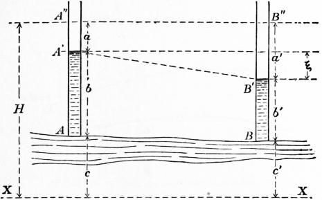
Fig. 26.
§ 30. Second Form of the Theorem of Bernoulli.—Suppose at the two sections A, B (fig. 26) of an elementary stream small vertical pipes are introduced, which may be termed pressure columns (§ 8), having their lower ends accurately parallel to the direction of flow. In such tubes the water will rise to heights corresponding to the pressures at A and B. Hence b = p/G, and b′ = p1/G. Consequently the tops of the pressure columns A′ and B′ will be at total heights b + c = p/G + z and b′ + c′ = p1/G + z1 above the datum line XX. The difference of level of the pressure column tops, or the fall of free surface level between A and B, is therefore
ξ = (p − p1) / G + (z − z1);
and this by equation (1), § 29 is (v12 − v2)/2g. That is, the fall of free, surface level between two sections is equal to the difference of the heights due to the velocities at the sections. The line A′B′ is sometimes called the line of hydraulic gradient, though this term is also used in cases where friction needs to be taken into account. It is the line the height of which above datum is the sum of the elevation and pressure head at that point, and it falls below a horizontal line A″B″ drawn at H ft. above XX by the quantities a = v2/2g and a′ = v12/2g, when friction is absent.
§ 31. Illustrations of the Theorem of Bernoulli. In a lecture to the mechanical section of the British Association in 1875, W. Froude gave some experimental illustrations of the principle of Bernoulli. He remarked that it was a common but erroneous impression that a fluid exercises in a contracting pipe A (fig. 27) an excess of pressure against the entire converging surface which it meets, and that, conversely, as it enters an enlargement B, a relief of pressure is experienced by the entire diverging surface of the pipe. Further it is commonly assumed that when passing through a contraction C, there is in the narrow neck an excess of pressure due to the squeezing together of the liquid at that point. These impressions are in no respect correct; the pressure is smaller as the section of the pipe is smaller and conversely.
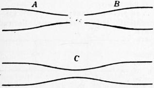
Fig. 27.
Fig. 28 shows a pipe so formed that a contraction is followed by an enlargement, and fig. 29 one in which an enlargement is followed by a contraction. The vertical pressure columns show the decrease of pressure at the contraction and increase of pressure at the enlargement. The line abc in both figures shows the variation of free surface level, supposing the pipe frictionless. In actual pipes, however, work is expended in friction against the pipe; the total head diminishes in proceeding along the pipe, and the free surface level is a line such as ab1c1, falling below abc.
Froude further pointed out that, if a pipe contracts and enlarges again to the same size, the resultant pressure on the converging part exactly balances the resultant pressure on the diverging part so that there is no tendency to move the pipe bodily when water flows through it. Thus the conical part AB (fig. 30) presents the same projected surface as HI, and the pressures parallel to the axis of the pipe, normal to these projected surfaces, balance each other. Similarly the pressures on BC, CD balance those on GH, EG. In the same way, in any combination of enlargements and contractions, a balance of pressures, due to the flow of liquid parallel to the axis of the pipe, will be found, provided the sectional area and direction of the ends are the same.
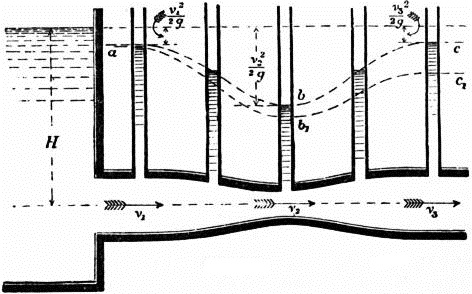
Fig. 28.
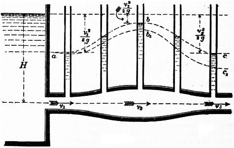
Fig. 29.
The following experiment is interesting. Two cisterns provided with converging pipes were placed so that the jet from one was exactly opposite the entrance to the other. The cisterns being filled very nearly to the same level, the jet from the left-hand cistern A entered the right-hand cistern B (fig. 31), shooting across the free space between them without any waste, except that due to indirectness of aim and want of exact correspondence in the form of the orifices. In the actual experiment there was 18 in. of head in the right and 201⁄2 in. of head in the left-hand cistern, so that about 21⁄2 in. were wasted in friction. It will be seen that in the open space between the orifices there was no pressure, except the atmospheric pressure acting uniformly throughout the system.

Fig. 30.
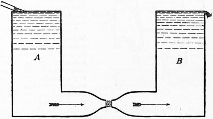
Fig. 31.
§ 32. Venturi Meter.—An ingenious application of the variation of pressure and velocity in a converging and diverging pipe has been made by Clemens Herschel in the construction of what he terms a Venturi Meter for measuring the flow in water mains. Suppose that, as in fig. 32, a contraction is made in a water main, the change of section being gradual to avoid the production of eddies. The ratio ρ of the cross sections at A and B, that is at inlet and throat, is in actual meters 5 to 1 to 20 to 1, and is very carefully determined by the maker of the meter. Then, if v and u are the velocities at A and B, u = ρv. Let pressure pipes be introduced at A, B and C, and let H1, H, H2 be the pressure heads at those points. Since the velocity at B is greater than at A the pressure will be less. Neglecting friction
H1 + v2/2g = H + u2/2g,
H1 − H = (u2 − v2) / 2g = (ρ2 − 1) v2 2g.
Let h = H1 − H be termed the Venturi head, then
u = √ { ρ2.2gh / (ρ2 − 1) },
from which the velocity through the throat and the discharge of the main can be calculated if the areas at A and B are known and h observed. Thus if the diameters at A and B are 4 and 12 in., the areas are 12.57 and 113.1 sq. in., and ρ = 9,
u = √ 81/80 √ (2gh) = 1.007 √ (2gh).
If the observed Venturi head is 12 ft.,
u = 28 ft. per sec.,
and the discharge of the main is
28 × 12.57 = 351 cub. ft. per sec.
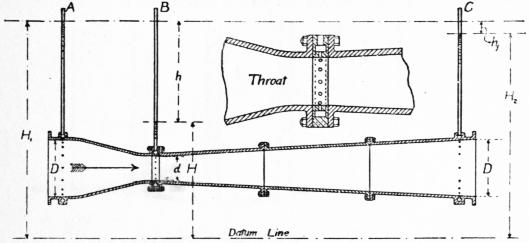
Fig. 32.
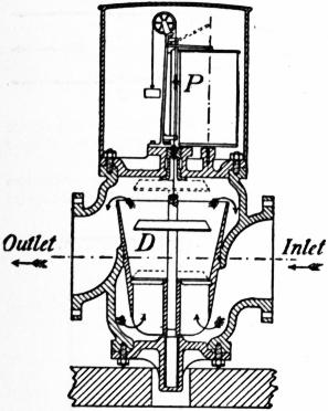
Fig. 33.
Hence by a simple observation of pressure difference, the flow in the main at any moment can be determined. Notice that the pressure height at C will be the same as at A except for a small loss hf due to friction and eddying between A and B. To get the pressure at the throat very exactly Herschel surrounds it by an annular passage communicating with the throat by several small holes, sometimes formed in vulcanite to prevent corrosion. Though constructed to prevent eddying as much as possible there is some eddy loss. The main effect of this is to cause a loss of head between A and C which may vary from a fraction of a foot to perhaps 5 ft. at the highest velocities at which a meter can be used. The eddying also affects a little the Venturi head h. Consequently an experimental coefficient must be determined for each meter by tank measurement. The range of this coefficient is, however, surprisingly small. If to allow for friction, u = k √ {ρ2/(ρ2 − 1)} √(2gh), then Herschel found values of k from 0.97 to 1.0 for throat velocities varying from 8 to 28 ft. per sec. The meter is extremely convenient. At Staines reservoirs there are two meters of this type on mains 94 in. in diameter. Herschel contrived a recording arrangement which records the variation of flow from hour to hour and also the total flow in any given time. In Great Britain the meter is constructed by G. Kent, who has made improvements in the recording arrangement.
In the Deacon Waste Water Meter (fig. 33) a different principle is used. A disk D, partly counter-balanced by a weight, is suspended in the water flowing through the main in a conical chamber. The unbalanced weight of the disk is supported by the impact of the water. If the discharge of the main increases the disk rises, but as it rises its position in the chamber is such that in consequence of the larger area the velocity is less. It finds, therefore, a new position of equilibrium. A pencil P records on a drum moved by clockwork the position of the disk, and from this the variation of flow is inferred.
§ 33. Pressure, Velocity and Energy in Different Stream Lines.—The equation of Bernoulli gives the variation of pressure and velocity from point to point along a stream line, and shows that the total energy of the flow across any two sections is the same. Two other directions may be defined, one normal to the stream line and in the plane containing its radius of curvature at any point, the other normal to the stream line and the radius of curvature. For the problems most practically useful it will be sufficient to consider the stream lines as parallel to a vertical or horizontal plane. If the motion is in a vertical plane, the action of gravity must be taken into the reckoning; if the motion is in a horizontal plane, the terms expressing variation of elevation of the filament will disappear.3
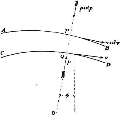
Fig. 34.
Let AB, CD (fig. 34) be two consecutive stream lines, at present assumed to be in a vertical plane, and PQ a normal to these lines making an angle φ with the vertical. Let P, Q be two particles moving along these lines at a distance PQ = ds, and let z be the height of Q above the horizontal plane with reference to which the energy is measured, v its velocity, and p its pressure. Then, if H is the total energy at Q per unit of weight of fluid,
H = z + p/G + v2/2g.
Differentiating, we get
dH = dz + dp/G + v dv/g,
(1)
for the increment of energy between Q and P. But
dz = PQ cos φ = ds cos φ;
∴ dH = dp/G + v dv/g + ds cos φ,
(1a)
where the last term disappears if the motion is in a horizontal plane.
Now imagine a small cylinder of section ω described round PQ as an axis. This will be in equilibrium under the action of its centrifugal force, its weight and the pressure on its ends. But its volume is ωds and its weight Gω ds. Hence, taking the components of the forces parallel to PQ—
ω dp = Gv2ω ds/gρ − Gω cos φ ds,
where ρ is the radius of curvature of the stream line at Q. Consequently, introducing these values in (1),
dH = v2 ds/gρ + v dv/g = (v/g) (v/ρ + dv/ds) ds.
(2)
Currents
§ 34. Rectilinear Current.—Suppose the motion is in parallel straight stream lines (fig. 35) in a vertical plane. Then ρ is infinite, and from eq. (2), § 33,
dH = v dv/g.
Comparing this with (1) we see that
dz + dp/G = 0;
∴ z + p/G = constant;
(3)
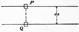
Fig. 35.
or the pressure varies hydrostatically as in a fluid at rest. For two stream lines in a horizontal plane, z is constant, and therefore p is constant.
Radiating Current.—Suppose water flowing radially between horizontal parallel planes, at a distance apart = δ. Conceive two cylindrical sections of the current at radii r1 and r2, where the velocities are v1 and v2, and the pressures p1 and p2. Since the flow across each cylindrical section of the current is the same,
Q = 2πr1 δv1 = 2πr2 δv2
r1v1 = r2v2
r1/r2 = v2/v1.
(4)
The velocity would be infinite at radius 0, if the current could be conceived to extend to the axis. Now, if the motion is steady,
H = p1/G + v12/2g = p2/G + v22/2g;
= p2/G + r12 + v12 / r222g;
(p2 − p1) / G = v12 (1 − r12/r22) / 2g;
(5)
p2/G = H − r12v12 / r222g.
(6)
Hence the pressure increases from the interior outwards, in a way indicated by the pressure columns in fig. 36, the curve through the free surfaces of the pressure columns being, in a radial section, the quasi-hyperbola of the form xy2 = c3. This curve is asymptotic to a horizontal line, H ft. above the line from which the pressures are measured, and to the axis of the current.
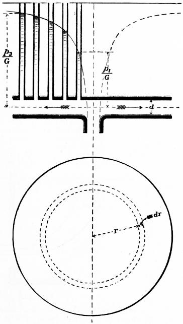
Fig. 36.
Free Circular Vortex.—A free circular vortex is a revolving mass of water, in which the stream lines are concentric circles, and in which the total head for each stream line is the same. Hence, if by any slow radial motion portions of the water strayed from one stream line to another, they would take freely the velocities proper to their new positions under the action of the existing fluid pressures only.
For such a current, the motion being horizontal, we have for all the circular elementary streams
H = p/G + v2/2g = constant;
∴ dH = dp/G + v dv/g = 0.
(7)
Consider two stream lines at radii r and r + dr (fig. 36). Then in (2), § 33, ρ = r and ds = dr,
v2 dr/gr + v dv/g = 0,
dv/v = −dr/r,
v ∞ 1/r,
(8)
precisely as in a radiating current; and hence the distribution of pressure is the same, and formulae 5 and 6 are applicable to this case.
Free Spiral Vortex.—As in a radiating and circular current the equations of motion are the same, they will also apply to a vortex in which the motion is compounded of these motions in any proportions, provided the radial component of the motion varies inversely as the radius as in a radial current, and the tangential component varies inversely as the radius as in a free vortex. Then the whole velocity at any point will be inversely proportional to the radius of the point, and the fluid will describe stream lines having a constant inclination to the radius drawn to the axis of the current. That is, the stream lines will be logarithmic spirals. When water is delivered from the circumference of a centrifugal pump or turbine into a chamber, it forms a free vortex of this kind. The water flows spirally outwards, its velocity diminishing and its pressure increasing according to the law stated above, and the head along each spiral stream line is constant.
§ 35. Forced Vortex.—If the law of motion in a rotating current is different from that in a free vortex, some force must be applied to cause the variation of velocity. The simplest case is that of a rotating current in which all the particles have equal angular velocity, as for instance when they are driven round by radiating paddles revolving uniformly. Then in equation (2), § 33, considering two circular stream lines of radii r and r + dr (fig. 37), we have ρ = r, ds = dr. If the angular velocity is α, then v = αr and dv = αdr. Hence
dH = α2r dr/g + α2r dr/g = 2α2r dr/g.
Comparing this with (1), § 33, and putting dz = 0, because the motion is horizontal,
dp/G + α2r dr/g = 2α2r dr/g,
dp/G = α2r dr/g,
p/G = α2/2g + constant.
(9)
Let p1, r1, v1 be the pressure, radius and velocity of one cylindrical section, p2, r2, v2 those of another; then
p1/G − α2r12 / 2g = p2/G − α2r22/2g;
(p2 − p1) / G = α2 (r22 − r12) / 2g = (v22 − v12) / 2g.
(10)
That is, the pressure increases from within outwards in a curve which in radial sections is a parabola, and surfaces of equal pressure are paraboloids of revolution (fig. 37).
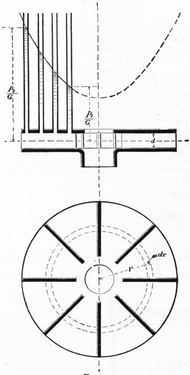
Fig. 37.
Dissipation of Head in Shock
§ 36. Relation of Pressure and Velocity in a Stream in Steady Motion when the Changes of Section of the Stream are Abrupt.—When a stream changes section abruptly, rotating eddies are formed which dissipate energy. The energy absorbed in producing rotation is at once abstracted from that effective in causing the flow, and sooner or later it is wasted by frictional resistances due to the rapid relative motion of the eddying parts of the fluid. In such cases the work thus expended internally in the fluid is too important to be neglected, and the energy thus lost is commonly termed energy lost in shock. Suppose fig. 38 to represent a stream having such an abrupt change of section. Let AB, CD be normal sections at points where ordinary stream line motion has not been disturbed and where it has been re-established. Let ω, p, v be the area of section, pressure and velocity at AB, and ω1, p1, v1 corresponding quantities at CD. Then if no work were expended internally, and assuming the stream horizontal, we should have
p/G + v2/2g = p1/G + v12/2g.
(1)
But if work is expended in producing irregular eddying motion, the head at the section CD will be diminished.
Suppose the mass ABCD comes in a short time t to A′B′C′D′. The resultant force parallel to the axis of the stream is
pω + p0 (ω1 − ω) − p1ω1,
where p0 is put for the unknown pressure on the annular space between AB and EF. The impulse of that force is
{ pω + p0 (ω1 − ω) − p1ω1 } t.
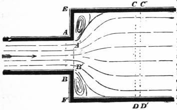
Fig. 38.
The horizontal change of momentum in the same time is the difference of the momenta of CDC′D′ and ABA′B′, because the amount of momentum between A′B′ and CD remains unchanged if the motion is steady. The volume of ABA′B′ or CDC′D′, being the inflow and outflow in the time t, is Qt = ωvt = ω1v1t, and the momentum of these masses is (G/g) Qvt and (G/g) Qv1t. The change of momentum is therefore (G/g) Qt (v1 − v). Equating this to the impulse,
{ pω + p0 (ω1 − ω) − p1ω1 } t = (G/g) Qt (v1 − v).
Assume that p0 = p, the pressure at AB extending unchanged through the portions of fluid in contact with AE, BF which lie out of the path of the stream. Then (since Q = ω1v1)
(p − p1) = (G/g) v1 (v1 − v);
p/G − p1/G = v1 (v1 − v) / g;
(2)
p/G + v2/2g = p1/G + v12/2g + (v − v1)2 / 2g.
(3)
This differs from the expression (1), § 29, obtained for cases where no sensible internal work is done, by the last term on the right. That is, (v − v1)2 / 2g has to be added to the total head at CD, which is p1/G + v12/2g, to make it equal to the total head at AB, or (v − v1)2 / 2g is the head lost in shock at the abrupt change of section. But (v − v1) is the relative velocity of the two parts of the stream. Hence, when an abrupt change of section occurs, the head due to the relative velocity is lost in shock, or (v − v1)2/2g foot-pounds of energy is wasted for each pound of fluid. Experiment verifies this result, so that the assumption that p0 = p appears to be admissible.
If there is no shock,
p1/G = p/G + (v2 − v12) / 2g.
If there is shock,
p1/G = p/G − v1 (v1 − v) / g.
Hence the pressure head at CD in the second case is less than in the former by the quantity (v − v1)2 / 2g, or, putting ω1v1 = ωv, by the quantity
(v2/2g) (1 − ω/ω1)2.
(4)
V. THEORY OF THE DISCHARGE FROM ORIFICES AND MOUTHPIECES
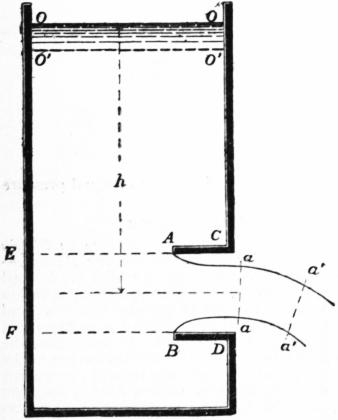
Fig. 39.
§ 37. Minimum Coefficient of Contraction. Re-entrant Mouthpiece of Borda.—In one special case the coefficient of contraction can be determined theoretically, and, as it is the case where the convergence of the streams approaching the orifice takes place through the greatest possible angle, the coefficient thus determined is the minimum coefficient.
Let fig. 39 represent a vessel with vertical sides, OO being the free water surface, at which the pressure is pa. Suppose the liquid issues by a horizontal mouthpiece, which is re-entrant and of the greatest length which permits the jet to spring clear from the inner end of the orifice, without adhering to its sides. With such an orifice the velocity near the points CD is negligible, and the pressure at those points may be taken equal to the hydrostatic pressure due to the depth from the free surface. Let Ω be the area of the mouthpiece AB, ω that of the contracted jet aa Suppose that in a short time t, the mass OOaa comes to the position O′O′ a′a′; the impulse of the horizontal external forces acting on the mass during that time is equal to the horizontal change of momentum.
The pressure on the side OC of the mass will be balanced by the pressure on the opposite side OE, and so for all other portions of the vertical surfaces of the mass, excepting the portion EF opposite the mouthpiece and the surface AaaB of the jet. On EF the pressure is simply the hydrostatic pressure due to the depth, that is, (pa + Gh). On the surface and section AaaB of the jet, the horizontal resultant of the pressure is equal to the atmospheric pressure pa acting on the vertical projection AB of the jet; that is, the resultant pressure is −paΩ. Hence the resultant horizontal force for the whole mass OOaa is (pa + Gh) Ω − paΩ = GhΩ. Its impulse in the time t is GhΩt. Since the motion is steady there is no change of momentum between O′O′ and aa. The change of horizontal momentum is, therefore, the difference of the horizontal momentum lost in the space OOO′O′ and gained in the space aaa′a′. In the former space there is no horizontal momentum.
The volume of the space aaa′a′ is ωvt; the mass of liquid in that space is (G/g)ωvt; its momentum is (G/g)ωv2t. Equating impulse to momentum gained,
GhΩt = (G/g) ωv2t;
∴ ω/Ω = gh/v2
But
v2 = 2gh, and ω/Ω = cc;
∴ ω/Ω = 1⁄2 = cc;
a result confirmed by experiment with mouthpieces of this kind. A similar theoretical investigation is not possible for orifices in plane surfaces, because the velocity along the sides of the vessel in the neighbourhood of the orifice is not so small that it can be neglected. The resultant horizontal pressure is therefore greater than GhΩ, and the contraction is less. The experimental values of the coefficient of discharge for a re-entrant mouthpiece are 0.5149 (Borda), 0.5547 (Bidone), 0.5324 (Weisbach), values which differ little from the theoretical value, 0.5, given above.
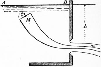
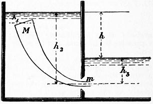
Fig. 40. Fig. 41.
§ 38. Velocity of Filaments issuing in a Jet.—A jet is composed of fluid filaments or elementary streams, which start into motion at some point in the interior of the vessel from which the fluid is discharged, and gradually acquire the velocity of the jet. Let Mm, fig. 40 be such a filament, the point M being taken where the velocity is insensibly small, and m at the most contracted section of the jet, where the filaments have become parallel and exercise uniform mutual pressure. Take the free surface AB for datum line, and let p1, v1, h1, be the pressure, velocity and depth below datum at M; p, v, h, the corresponding quantities at m. Then § 29, eq. (3a),
v12/2g + p1/G − h1 = v2/2g + p/G − h
(1)
But at M, since the velocity is insensible, the pressure is the hydrostatic pressure due to the depth; that is v1 = 0, p1 = pa + Gh1. At m, p = pa, the atmospheric pressure round the jet. Hence, inserting these values,
0 + pa/G + h1 − h1 = v2/2g + pa / G − h;
v2/2g = h;
(2)
or
v = √ (2gh) = 8.025V √ h.
(2a)
That is, neglecting the viscosity of the fluid, the velocity of filaments at the contracted section of the jet is simply the velocity due to the difference of level of the free surface in the reservoir and the orifice. If the orifice is small in dimensions compared with h, the filaments will all have nearly the same velocity, and if h is measured to the centre of the orifice, the equation above gives the mean velocity of the jet.
Case of a Submerged Orifice.—Let the orifice discharge below the level of the tail water. Then using the notation shown in fig. 41, we have at M, v1 = 0, p1 = Gh; + pa at m, p = Gh3 + pa. Inserting these values in (3), § 29,
0 + h1 + pa/G − h1 = v2/2g + h3 − h22 + pa/G;
v2/2g = h2 − h3 = h,
(3)
where h is the difference of level of the head and tail water, and may be termed the effective head producing flow.
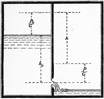
Fig. 42.
Case where the Pressures are different on the Free Surface and at the Orifice.—Let the fluid flow from a vessel in which the pressure is p0 into a vessel in which the pressure is p, fig. 42. The pressure p0 will produce the same effect as a layer of fluid of thickness p0/G added to the head water; and the pressure p, will produce the same effect as a layer of thickness p/G added to the tail water. Hence the effective difference of level, or effective head producing flow, will be
h = h0 + p0/G − p/G;
and the velocity of discharge will be
v = √ [ 2g { h0 + (p0 − p) / G } ].
(4)
We may express this result by saying that differences of pressure at the free surface and at the orifice are to be reckoned as part of the effective head.
Hence in all cases thus far treated the velocity of the jet is the velocity due to the effective head, and the discharge, allowing for contraction of the jet, is
Q = cωv = cω √ (2gh),
(5)
where ω is the area of the orifice, cω the area of the contracted section of the jet, and h the effective head measured to the centre of the orifice. If h and ω are taken in feet, Q is in cubic feet per second.
It is obvious, however, that this formula assumes that all the filaments have sensibly the same velocity. That will be true for horizontal orifices, and very approximately true in other cases, if the dimensions of the orifice are not large compared with the head h. In large orifices in say a vertical surface, the value of h is different for different filaments, and then the velocity of different filaments is not sensibly the same.
Simple Orifices—Head Constant
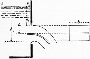
Fig. 43.
§ 39. Large Rectangular Jets from Orifices in Vertical Plane Surfaces.—Let an orifice in a vertical plane surface be so formed that it produces a jet having a rectangular contracted section with vertical and horizontal sides. Let b (fig. 43) be the breadth of the jet, h1 and h2 the depths below the free surface of its upper and lower surfaces. Consider a lamina of the jet between the depths h and h + dh. Its normal section is bdh, and the velocity of discharge √2gh. The discharge per second in this lamina is therefore b√2gh dh, and that of the whole jet is therefore
Q = ∫h2h1 b √ (2gh) dh
= 2⁄3 b √2g { h23/2 − h13/2 },
(6)
where the first factor on the right is a coefficient depending on the form of the orifice.
Now an orifice producing a rectangular jet must itself be very approximately rectangular. Let B be the breadth, H1, H2, the depths to the upper and lower edges of the orifice. Put
b (h23/2 − h13/2) / B (H23/2 − H13/2) = c.
(7)
Then the discharge, in terms of the dimensions of the orifice, instead of those of the jet, is
Q = 2⁄3 cB √2g (H23/2 − H13/2),
(8)
the formula commonly given for the discharge of rectangular orifices. The coefficient c is not, however, simply the coefficient of contraction, the value of which is
b (h2 − h1) / B (H2 − H1),
and not that given in (7). It cannot be assumed, therefore, that c in equation (8) is constant, and in fact it is found to vary for different values of B/H2 and B/H1, and must be ascertained experimentally.
Relation between the Expressions (5) and (8).—For a rectangular orifice the area of the orifice is ω = B(H2 − H1), and the depth measured to its centre is 1⁄2 (H2 + H1). Putting these values in (5),
Q1 = cB (H2 − H1) √ {g (H2 + H1) }.
From (8) the discharge is
Q2 = 2⁄3 cB √2g (H23/2 − H13/2).
Hence, for the same value of c in the two cases,
Q2/Q1 = 2⁄3 (H23/2 − H13/2) / [ (H2 − H1) √ { (H2 + H1)/2} ].
Let H1/H2 = σ, then
Q2/Q1 = 0.9427 (1 − σ3/2) / {1 − σ √ (1 + σ) }.
(9)
If H1 varies from 0 to ∞, σ( = H1/H2) varies from 0 to 1. The following table gives values of the two estimates of the discharge for different values of σ:—
H1/H2 = σ. Q2/Q1. H1/H2 = σ. Q2/Q1.
0.0 .943 0.8 .999
0.2 .979 0.9 .999
0.5 .995 1.0 1.000
0.7 .998
Hence it is obvious that, except for very small values of σ, the simpler equation (5) gives values sensibly identical with those of (8). When σ < 0.5 it is better to use equation (8) with values of c determined experimentally for the particular proportions of orifice which are in question.
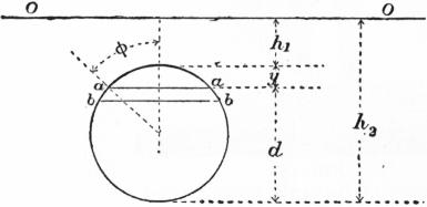
Fig. 44.
§ 40. Large Jets having a Circular Section from Orifices in a Vertical Plane Surface.—Let fig. 44 represent the section of the jet, OO being the free surface level in the reservoir. The discharge through the horizontal strip aabb, of breadth aa = b, between the depths h1 + y and h1 + y + dy, is
dQ = b √ {2g (h1 + y) } dy.
The whole discharge of the jet is
Q = ∫d0 b √ { 2g (h1 + y) } dy.
But b = d sin φ; y = 1⁄2d (1 − cos φ); dy = 1⁄2d sin φ dφ. Let ε = d/(2h1 + d), then
Q = 1⁄2d2 √ { 2g (h1 + d/2) } ∫π0 sin2 φ √1 − ε cos φ dφ.
From eq. (5), putting ω = πd2/4, h = h1 + d/2, c = 1 when d is the diameter of the jet and not that of the orifice,
Q1 = 1⁄4πd2 √ {2g (h1 + d/2) },
Q/Q1 = 2/π ∫π0 sin2 φ √ {1 − ε cos φ} dφ.
For
h1 = ∞, ε = 0 and Q/Q1 = 1;
and for
h1 = 0, ε = 1 and Q/Q1 = 0.96.
So that in this case also the difference between the simple formula (5) and the formula above, in which the variation of head at different parts of the orifice is taken into account, is very small.
Notches and Weirs
§ 41. Notches, Weirs and Byewashes.—A notch is an orifice extending up to the free surface level in the reservoir from which the discharge takes place. A weir is a structure over which the water flows, the discharge being in the same conditions as for a notch. The formula of discharge for an orifice of this kind is ordinarily deduced by putting H1 = 0 in the formula for the corresponding orifice, obtained as in the preceding section. Thus for a rectangular notch, put H1 = 0 in (8). Then
Q = 2⁄3 cB √(2g) H3/2,
(11)
where H is put for the depth to the crest of the weir or the bottom of the notch. Fig. 45 shows the mode in which the discharge occurs in the case of a rectangular notch or weir with a level crest. As, the free surface level falls very sensibly near the notch, the head H should be measured at some distance back from the notch, at a point where the velocity of the water is very small.
Since the area of the notch opening is BH, the above formula is of the form
Q = c × BH × k √(2gH),
where k is a factor depending on the form of the notch and expressing the ratio of the mean velocity of discharge to the velocity due to the depth H.
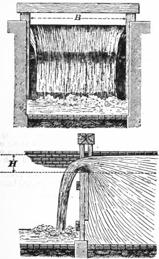
Fig. 45.
§ 42. Francis’s Formula for Rectangular Notches.—The jet discharged through a rectangular notch has a section smaller than BH, (a) because of the fall of the water surface from the point where H is measured towards the weir, (b) in consequence of the crest contraction, (c) in consequence of the end contractions. It may be pointed out that while the diminution of the section of the jet due to the surface fall and to the crest contraction is proportional to the length of the weir, the end contractions have nearly the same effect whether the weir is wide or narrow.
J. B. Francis’s experiments showed that a perfect end contraction, when the heads varied from 3 to 24 in., and the length of the weir was not less than three times the head, diminished the effective length of the weir by an amount approximately equal to one-tenth of the head. Hence, if l is the length of the notch or weir, and H the head measured behind the weir where the water is nearly still, then the width of the jet passing through the notch would be l − 0.2H, allowing for two end contractions. In a weir divided by posts there may be more than two end contractions. Hence, generally, the width of the jet is l − 0.1nH, where n is the number of end contractions of the stream. The contractions due to the fall of surface and to the crest contraction are proportional to the width of the jet. Hence, if cH is the thickness of the stream over the weir, measured at the contracted section, the section of the jet will be c(l − 0.1nH)H and (§ 41) the mean velocity will be 2⁄3 √(2gH). Consequently the discharge will be given by an equation of the form
Q = 2⁄3 c (l − 0.1nH) H √2gH
= 5.35c (l − 0.1nH) H3/2.
This is Francis’s formula, in which the coefficient of discharge c is much more nearly constant for different values of l and h than in the ordinary formula. Francis found for c the mean value 0.622, the weir being sharp-edged.
§ 43. Triangular Notch (fig. 46).—Consider a lamina issuing between the depths h and h + dh. Its area, neglecting contraction, will be bdh, and the velocity at that depth is √(2gh). Hence the discharge for this lamina is
b√2gh dh.
But
B/b = H / (H − h); b = B (H − h) / H.
Hence discharge of lamina
= B(H − h) √(2gh) dh/H;
and total discharge of notch
= Q = B √(2g) ∫H0 (H − h) h1/2 dh/H
= 4⁄15 B √(2g) H3/2.
or, introducing a coefficient to allow for contraction,
Q = 4⁄15 cB √(2g) H1/2,
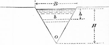
Fig. 46.
When a notch is used to gauge a stream of varying flow, the ratio B/H varies if the notch is rectangular, but is constant if the notch is triangular. This led Professor James Thomson to suspect that the coefficient of discharge, c, would be much more constant with different values of H in a triangular than in a rectangular notch, and this has been experimentally shown to be the case. Hence a triangular notch is more suitable for accurate gaugings than a rectangular notch. For a sharp-edged triangular notch Professor J. Thomson found c = 0.617. It will be seen, as in § 41, that since 1⁄2BH is the area of section of the stream through the notch, the formula is again of the form
Q = c × 1⁄2BH × k √(2gH),
where k = 8⁄15 is the ratio of the mean velocity in the notch to the velocity at the depth H. It may easily be shown that for all notches the discharge can be expressed in this form.
Coefficients for the Discharge over Weirs, derived from the Experiments of T. E. Blackwell. When more than one experiment was made with the same head, and the results were pretty uniform, the resulting coefficients are marked with an (*). The effect of the converging wing-boards is very strongly marked.
Heads in inches measured from still Water in Reservoir. Sharp Edge. Planks 2 in. thick, square on Crest. Crests 3 ft. wide.
3 ft. long. 10 ft. long. 3 ft. long. 6 ft. long. 10 ft. long. 10 ft. long, wing-boards making an angle of 60°. 3 ft. long. level. 3 ft. long, fall 1 in 18. 3 ft. long, fall 1 in 12. 6 ft. long. level. 10 ft. long. level. 10 ft. long, fall 1 in 18.
1 .677 .809 .467 .459 .4354 .754 .452 .545 .467 .. .381 .467
2 .675 .803 .509* .561 .585* .675 .482 .546 .533 .. .479* .495*
3 .630 .642* .563* .597* .569* .. .441 .537 .539 .492* .. ..
4 .617 .656 .549 .575 .602* .656 .419 .431 .455 .497* .. .515
5 .602 .650* .588 .601* .609* .671 .479 .516 .. .. .518 ..
6 .593 .. .593* .608* .576* .. .501* .. .531 .507 .513 .543
7 .. .. .617* .608* .576* .. .488 .513 .527 .497 .. ..
8 .. .581 .606* .590* .548* .. .470 .491 .. .. .468 .507
9 .. .530 .600 .569* .558* .. .476 .492* .498 .480* .486 ..
10 .. .. .614* .539 .534* .. .. .. .. .465* .455 ..
12 .. .. .. .525 .534* .. .. .. .. .467* .. ..
14 .. .. .. .549* .. .. .. .. .. .. .. ..
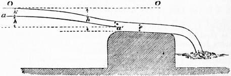
Fig. 47.
§ 44. Weir with a Broad Sloping Crest.—Suppose a weir formed with a broad crest so sloped that the streams flowing over it have a movement sensibly rectilinear and uniform (fig. 47). Let the inner edge be so rounded as to prevent a crest contraction. Consider a filament aa′, the point a being so far back from the weir that the velocity of approach is negligible. Let OO be the surface level in the reservoir, and let a be at a height h″ below OO, and h′ above a′. Let h be the distance from OO to the weir crest and e the thickness of the stream upon it. Neglecting atmospheric pressure, which has no influence, the pressure at a is Gh″; at a′ it is Gz. If v be the velocity at a′,
v2/2g = h′ + h″ − z = h − e;
Q = be √2g (h − e).
Theory does not furnish a value for e, but Q = 0 for e = 0 and for e = h. Q has therefore a maximum for a value of e between 0 and h, obtained by equating dQ/de to zero. This gives e = 2⁄3h, and, inserting this value,
Q = 0.385 bh √2gh,
as a maximum value of the discharge with the conditions assigned. Experiment shows that the actual discharge is very approximately equal to this maximum, and the formula is more legitimately applicable to the discharge over broad-crested weirs and to cases such as the discharge with free upper surface through large masonry sluice openings than the ordinary weir formula for sharp-edged weirs. It should be remembered, however, that the friction on the sides and crest of the weir has been neglected, and that this tends to reduce a little the discharge. The formula is equivalent to the ordinary weir formula with c = 0.577.
Special Cases of Discharge from Orifices
§ 45. Cases in which the Velocity of Approach needs to be taken into Account. Rectangular Orifices and Notches.—In finding the velocity at the orifice in the preceding investigations, it has been assumed that the head h has been measured from the free surface of still water above the orifice. In many cases which occur in practice the channel of approach to an orifice or notch is not so large, relatively to the stream through the orifice or notch, that the velocity in it can be disregarded.
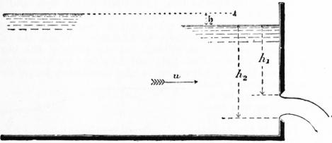
Fig. 48.
Let h1, h2 (fig. 48) be the heads measured from the free surface to the top and bottom edges of a rectangular orifice, at a point in the channel of approach where the velocity is u. It is obvious that a fall of the free surface,
ɧ = u2/2g
has been somewhere expended in producing the velocity u, and hence the true heads measured in still water would have been h1 + ɧ and h2 + ɧ. Consequently the discharge, allowing for the velocity of approach, is
Q = 2⁄3 cb √2g { (h2 + ɧ)3/2 − (h1 + ɧ)3/2 }.
(1)
And for a rectangular notch for which h1 = 0, the discharge is
Q = 2⁄3 cb √2g { (h2 + ɧ)3/2 − ɧ3/2 }.
(2)
In cases where u can be directly determined, these formulae give the discharge quite simply. When, however, u is only known as a function of the section of the stream in the channel of approach, they become complicated. Let Ω be the sectional area of the channel where h1 and h2 are measured. Then u = Q/Ω and ɧ = Q2/2g Ω2.
This value introduced in the equations above would render them excessively cumbrous. In cases therefore where Ω only is known, it is best to proceed by approximation. Calculate an approximate value Q′ of Q by the equation
Q′ = 2⁄3 cb √2g {h23/2 − h13/2 }.
Then ɧ = Q′2/2gΩ2 nearly. This value of ɧ introduced in the equations above will give a second and much more approximate value of Q.
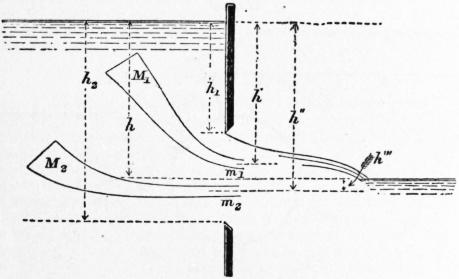
Fig. 49.
§ 46. Partially Submerged Rectangular Orifices and Notches.—When the tail water is above the lower but below the upper edge of the orifice, the flow in the two parts of the orifice, into which it is divided by the surface of the tail water, takes place under different conditions. A filament M1m1 (fig. 49) in the upper part of the orifice issues with a head h′ which may have any value between h1 and h. But a filament M2m2 issuing in the lower part of the orifice has a velocity due to h″ − h″′, or h, simply. In the upper part of the orifice the head is variable, in the lower constant. If Q1, Q2 are the discharges from the upper and lower parts of the orifice, b the width of the orifice, then
Q1 = 2⁄3 cb √2g { h3/2 − h13/2 }
Q2 = cb (h2 − h) √2gh.
(3)
In the case of a rectangular notch or weir, h1 = 0. Inserting this value, and adding the two portions of the discharge together, we get for a drowned weir
Q = cb √2gh (h2 − h/3),
(4)
where h is the difference of level of the head and tail water, and h2 is the head from the free surface above the weir to the weir crest (fig. 50).
From some experiments by Messrs A. Fteley and F.P. Stearns (Trans. Am. Soc. C.E., 1883, p. 102) some values of the coefficient c can be reduced
h3/h2 c h3/h2 c
0.1 0.629 0.7 0.578
0.2 0.614 0.8 0.583
0.3 0.600 0.9 0.596
0.4 0.590 0.95 0.607
0.5 0.582 1.00 0.628
0.6 0.578
If velocity of approach is taken into account, let ɧ be the head due to that velocity; then, adding ɧ to each of the heads in the equations (3), and reducing, we get for a weir
Q = cb √2g [ (h2 + ɧ) (h + ɧ)1/2 − 1⁄3 (h + ɧ)3/2 − 2⁄3 ɧ3/2 ];
(5)
an equation which may be useful in estimating flood discharges.
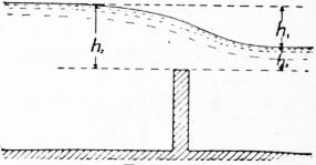
Fig. 50.
Bridge Piers and other Obstructions in Streams.—When the piers of a bridge are erected in a stream they create an obstruction to the flow of the stream, which causes a difference of surface-level above and below the pier (fig. 51). If it is necessary to estimate this difference of level, the flow between the piers may be treated as if it occurred over a drowned weir. But the value of c in this case is imperfectly known.
§ 47. Bazin’s Researches on Weirs.—H. Bazin has executed a long series of researches on the flow over weirs, so systematic and complete that they almost supersede other observations. The account of them is contained in a series of papers in the Annales des Ponts et Chaussées (October 1888, January 1890, November 1891, February 1894, December 1896, 2nd trimestre 1898). Only a very abbreviated account can be given here. The general plan of the experiments was to establish first the coefficients of discharge for a standard weir without end contractions; next to establish weirs of other types in series with the standard weir on a channel with steady flow, to compare the observed heads on the different weirs and to determine their coefficients from the discharge computed at the standard weir. A channel was constructed parallel to the Canal de Bourgogne, taking water from it through three sluices 0.3 × 1.0 metres. The water enters a masonry chamber 15 metres long by 4 metres wide where it is stilled and passes into the canal at the end of which is the standard weir. The canal has a length of 15 metres, a width of 2 metres and a depth of 0.6 metres. From this extends a channel 200 metres in length with a slope of 1 mm. per metre. The channel is 2 metres wide with vertical sides. The channels were constructed of concrete rendered with cement. The water levels were taken in chambers constructed near the canal, by floats actuating an index on a dial. Hook gauges were used in determining the heads on the weirs.
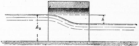
Fig. 51.
Standard Weir.—The weir crest was 3.72 ft. above the bottom of the canal and formed by a plate 1⁄4 in. thick. It was sharp-edged with free overfall. It was as wide as the canal so that end contractions were suppressed, and enlargements were formed below the crest to admit air under the water sheet. The channel below the weir was used as a gauging tank. Gaugings were made with the weir 2 metres in length and afterwards with the weir reduced to 1 metre and 0.5 metre in length, the end contractions being suppressed in all cases. Assuming the general formula
Q = mlh √(2gh),
(1)
Bazin arrives at the following values of m:—
Coefficients of Discharge of Standard Weir.
Head h metres. Head h feet. m
0.05 .164 0.4485
0.10 .328 0.4336
0.15 .492 0.4284
0.20 .656 0.4262
0.25 .820 0.4259
0.30 .984 0.4266
0.35 1.148 0.4275
0.40 1.312 0.4286
0.45 1.476 0.4299
0.50 1.640 0.4313
0.55 1.804 0.4327
0.60 1.968 0.4341
Bazin compares his results with those of Fteley and Stearns in 1877 and 1879, correcting for a different velocity of approach, and finds a close agreement.
Influence of Velocity of Approach.—To take account of the velocity of approach u it is usual to replace h in the formula by h + au2/2g where α is a coefficient not very well ascertained. Then
Q = μl (h + αu2/2g) √ { 2g (h + αu2/2g) }
= μlh √(2gh) (1 + αu2/2gh)3/2.
(2)
The original simple equation can be used if
m = μ (1 + αu2/2gh)3/2
or very approximately, since u2/2gh is small,
m = μ (1 + 3⁄2αu2/2gh).
(3)
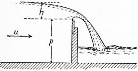
Fig. 52.
Now if p is the height of the weir crest above the bottom of the canal (fig. 52), u = Q/l(p + h). Replacing Q by its value in (1)
u2/2gh = Q2 / {2ghl2(p + h)2} = m2 {h/(p + h) }2,
(4)
so that (3) may be written
m = μ [1 + k {h/(p + h)}2 ].
(5)
Gaugings were made with weirs of 0.75, 0.50, 0.35, and 0.24 metres height above the canal bottom and the results compared with those of the standard weir taken at the same time. The discussion of the results leads to the following values of m in the general equation (1):—
m = μ (1 + 2.5u2/2gh)
= μ [1 + 0.55 {h/(p + h)}2 ].
Values of μ—
Head h metres. Head h feet. μ
0.05 .164 0.4481
0.10 .328 0.4322
0.20 .656 0.4215
0.30 .984 0.4174
0.40 1.312 0.4144
0.50 1.640 0.4118
0.60 1.968 0.4092
An approximate formula for μ is:
μ = 0.405 + 0.003/h (h in metres)
μ = 0.405 + 0.01/h (h in feet).
Inclined Weirs.—-Experiments were made in which the plank weir was inclined up or down stream, the crest being sharp and the end contraction suppressed. The following are coefficients by which the discharge of a vertical weir should be multiplied to obtain the discharge of the inclined weir.
Coefficient.
Inclination up stream 1 to 1 0.93
” ” 3 to 2 0.94
” ” 3 to 1 0.96
Vertical weir .. 1.00
Inclination down stream 3 to 1 1.04
” ” 3 to 2 1.07
” ” 1 to 1 1.10
” ” 1 to 2 1.12
” ” 1 to 4 1.09
The coefficient varies appreciably, if h/p approaches unity, which case should be avoided.
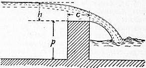
Fig. 53.
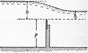
Fig. 54.
In all the preceding cases the sheet passing over the weir is detached completely from the weir and its under-surface is subject to atmospheric pressure. These conditions permit the most exact determination of the coefficient of discharge. If the sides of the canal below the weir are not so arranged as to permit the access of air under the sheet, the phenomena are more complicated. So long as the head does not exceed a certain limit the sheet is detached from the weir, but encloses a volume of air which is at less than atmospheric pressure, and the tail water rises under the sheet. The discharge is a little greater than for free overfall. At greater head the air disappears from below the sheet and the sheet is said to be “drowned.” The drowned sheet may be independent of the tail water level or influenced by it. In the former case the fall is followed by a rapid, terminating in a standing wave. In the latter case when the foot of the sheet is drowned the level of the tail water influences the discharge even if it is below the weir crest.
Weirs with Flat Crests.—The water sheet may spring clear from the upstream edge or may adhere to the flat crest falling free beyond the down-stream edge. In the former case the condition is that of a sharp-edged weir and it is realized when the head is at least double the width of crest. It may arise if the head is at least 11⁄2 the width of crest. Between these limits the condition of the sheet is unstable. When the sheet is adherent the coefficient m depends on the ratio of the head h to the width of crest c (fig. 53), and is given by the equation m = m1 [0.70 + 0.185h/c], where m1 is the coefficient for a sharp-edged weir in similar conditions. Rounding the upstream edge even to a small extent modifies the discharge. If R is the radius of the rounding the coefficient m is increased in the ratio 1 to 1 + R/h nearly. The results are limited to R less than 1⁄2 in.
Drowned Weirs.—Let h (fig. 54) be the height of head water and h1 that of tail water above the weir crest. Then Bazin obtains as the approximate formula for the coefficient of discharge
m = 1.05m1 [1 + 1⁄5 h1/p] 3√ { (h − h1) / h },
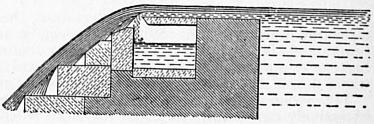
Fig. 55.
where as before m1 is the coefficient for a sharp-edged weir in similar conditions, that is, when the sheet is free and the weir of the same height.
§ 48. Separating Weirs.—Many towns derive their water-supply from streams in high moorland districts, in which the flow is extremely variable. The water is collected in large storage reservoirs, from which an uniform supply can be sent to the town. In such cases it is desirable to separate the coloured water which comes down the streams in high floods from the purer water of ordinary flow. The latter is sent into the reservoirs; the former is allowed to flow away down the original stream channel, or is stored in separate reservoirs and used as compensation water. To accomplish the separation of the flood and ordinary water, advantage is taken of the different horizontal range of the parabolic path of the water falling over a weir, as the depth on the weir and, consequently, the velocity change. Fig. 55 shows one of these separating weirs in the form in which they were first introduced on the Manchester Waterworks; fig. 56 a more modern weir of the same kind designed by Sir A. Binnie for the Bradford Waterworks. When the quantity of water coming down the stream is not excessive, it drops over the weir into a transverse channel leading to the reservoirs. In flood, the water springs over the mouth of this channel and is led into a waste channel.
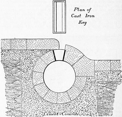
Fig. 56.
It may be assumed, probably with accuracy enough for practical purposes, that the particles describe the parabolas due to the mean velocity of the water passing over the weir, that is, to a velocity
2⁄3 √(2gh),
where h is the head above the crest of the weir.
Let cb = x be the width of the orifice and ac = y the difference of level of its edges (fig. 57). Then, if a particle passes from a to b in t seconds,
y = 1⁄2 gt2, x = 2⁄3 √(2gh)t;
∴ y = 9⁄16 x2/h,
which gives the width x for any given difference of level y and head h, which the jet will just pass over the orifice. Set off ad vertically and equal to 1⁄2g on any scale; af horizontally and equal to 2⁄3 √(gh). Divide af, fe into an equal number of equal parts. Join a with the divisions on ef. The intersections of these lines with verticals from the divisions on af give the parabolic path of the jet.
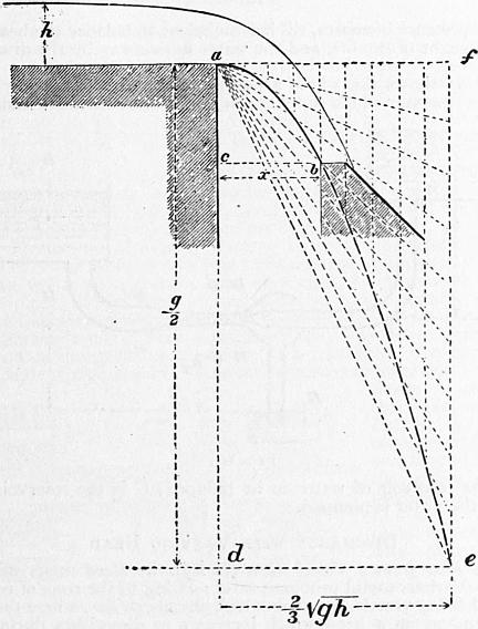
Fig. 57.
Mouthpieces—Head Constant
§ 49. Cylindrical Mouthpieces.—When water issues from a short cylindrical pipe or mouthpiece of a length at least equal to l1⁄2 times its smallest transverse dimension, the stream, after contraction within the mouthpiece, expands to fill it and issues full bore, or without contraction, at the point of discharge. The discharge is found to be about one-third greater than that from a simple orifice of the same size. On the other hand, the energy of the fluid per unit of weight is less than that of the stream from a simple orifice with the same head, because part of the energy is wasted in eddies produced at the point where the stream expands to fill the mouthpiece, the action being something like that which occurs at an abrupt change of section.
Let fig. 58 represent a vessel discharging through a cylindrical mouthpiece at the depth h from the free surface, and let the axis of the jet XX be taken as the datum with reference to which the head is estimated. Let Ω be the area of the mouthpiece, ω the area of the stream at the contracted section EF. Let v, p be the velocity and pressure at EF, and v1, p1 the same quantities at GH. If the discharge is into the air, p1 is equal to the atmospheric pressure pa.
The total head of any filament which goes to form the jet, taken at a point where its velocity is sensibly zero, is h + pa/G; at EF the total head is v2/2g + p/G; at GH it is v12/2g + p1/G.
Between EF and GH there is a loss of head due to abrupt change of velocity, which from eq. (3), § 36, may have the value
(v − v1)2/2g.
Adding this head lost to the head at GH, before equating it to the heads at EF and at the point where the filaments start into motion,—
h + pa/G = v2/2g + p/G = v12/2g + p1/G + (v − v1)2/2g.
But ωv = Ωv1, and ω = ccΩ, if cc is the coefficient of contraction within the mouthpiece. Hence
v = Ωv1/ω = v1/cc.
Supposing the discharge into the air, so that p1 = pa,
h + pa/G = v12/2g + pa/G + (v12/2g) (1/cc − 1)2;
(v1/2g) {1 + (1/cc − 1)2} = h;
∴ v1 = √(2gh) / √ {1 + (1/cc − 1)2 };
(1)
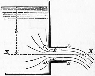
Fig. 58.
where the coefficient on the right is evidently the coefficient of velocity for the cylindrical mouthpiece in terms of the coefficient of contraction at EF. Let cc = 0.64, the value for simple orifices, then the coefficient of velocity is
cv = 1/√ {1 + (1/cc − 1)2 } = 0.87
(2)
The actual value of cv, found by experiment is 0.82, which does not differ more from the theoretical value than might be expected if the friction of the mouthpiece is allowed for. Hence, for mouthpieces of this kind, and for the section at GH,
cv = 0.82 cc = 1.00 c = 0.82,
Q = 0.82Ω √(2gh).
It is easy to see from the equations that the pressure p at EF is less than atmospheric pressure. Eliminating v1, we get
(pa − p)/G = 3⁄4 h nearly;
(3)
or
p = pa − 3⁄4 Gh ℔ per sq. ft.
If a pipe connected with a reservoir on a lower level is introduced into the mouthpiece at the part where the contraction is formed (fig. 59), the water will rise in this pipe to a height
KL = (pa − p) / G = 3⁄4 h nearly.
If the distance X is less than this, the water from the lower reservoir will be forced continuously into the jet by the atmospheric pressure, and discharged with it. This is the crudest form of a kind of pump known as the jet pump.
§ 50. Convergent Mouthpieces.—With convergent mouthpieces there is a contraction within the mouthpiece causing a loss of head, and a diminution of the velocity of discharge, as with cylindrical mouthpieces. There is also a second contraction of the stream outside the mouthpiece. Hence the discharge is given by an equation of the form
Q = cvccΩ √(2gh),
(4)
where Ω is the area of the external end of the mouthpiece, and ccΩ the section of the contracted jet beyond the mouthpiece.
Convergent Mouthpieces (Castel’s Experiments).—Smallest diameter of orifice = 0.05085 ft. Length of mouthpiece = 2.6 Diameters.
Angle of Convergence. Coefficient of Contraction, cc Coefficient of Velocity, cv Coefficient of Discharge, c
0° 0′ .999 .830 .829
1° 36′ 1.000 .866 .866
3° 10′ 1.001 .894 .895
4° 10′ 1.002 .910 .912
5° 26′ 1.004 .920 .924
7° 52′ .998 .931 .929
8° 58′ .992 .942 .934
10° 20′ .987 .950 .938
12° 4′ .986 .955 .942
13° 24′ .983 .962 .946
14° 28′ .979 .966 .941
16° 36′ .969 .971 .938
19° 28′ .953 .970 .924
21° 0′ .945 .971 .918
23° 0′ .937 .974 .913
29° 58′ .919 .975 .896
40° 20′ .887 .980 .869
48° 50′ .861 .984 .847
The maximum coefficient of discharge is that for a mouthpiece with a convergence of 13°24′.
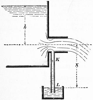
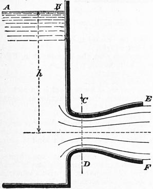
Fig. 59. Fig. 60.
The values of cv and cc must here be determined by experiment. The above table gives values sufficient for practical purposes. Since the contraction beyond the mouthpiece increases with the convergence, or, what is the same thing, cc diminishes, and on the other hand the loss of energy diminishes, so that cv increases with the convergence, there is an angle for which the product cc cv, and consequently the discharge, is a maximum.
§ 51. Divergent Conoidal Mouthpiece.—Suppose a mouthpiece so designed that there is no abrupt change in the section or velocity of the stream passing through it. It may have a form at the inner end approximately the same as that of a simple contracted vein, and may then enlarge gradually, as shown in fig. 60. Suppose that at EF it becomes cylindrical, so that the jet may be taken to be of the diameter EF. Let ω, v, p be the section, velocity and pressure at CD, and Ω, v1, p1 the same quantities at EF, pa being as usual the atmospheric pressure, or pressure on the free surface AB. Then, since there is no loss of energy, except the small frictional resistance of the surface of the mouthpiece,
h + pa/G = v2/2g + p/G = v12/2g + p1/G.
If the jet discharges into the air, p1 = pa; and
v12/2g = h;
v1 = √(2gh);
or, if a coefficient is introduced to allow for friction,
v1 = cv √(2gh);
where cv is about 0.97 if the mouthpiece is smooth and well formed.
Q = Ω v1 = cv Ω √(2gh).
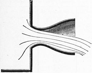
Fig. 61.
Hence the discharge depends on the area of the stream at EF, and not at all on that at CD, and the latter may be made as small as we please without affecting the amount of water discharged.
There is, however, a limit to this. As the velocity at CD is greater than at EF the pressure is less, and therefore less than atmospheric pressure, if the discharge is into the air. If CD is so contracted that p = 0, the continuity of flow is impossible. In fact the stream disengages itself from the mouthpiece for some value of p greater than 0 (fig. 61).
From the equations,
p/G = pa/G − (v2 − v12) / 2g.
Let Ω/ω = m. Then
v = v1m;
p/G = pa/G − v12 (m2 − 1) / 2g
= pa/G − (m2 − 1) h;
whence we find that p/G will become zero or negative if
Ω/ω ≥ √ {(h + pa/G) / h } = √ {1 + pa/Gh};
or, putting pa/G = 34 ft., if
Ω/ω ≥ √ { (h + 34)/h}.
In practice there will be an interruption of the full bore flow with a less ratio of Ω/ω, because of the disengagement of air from the water. But, supposing this does not occur, the maximum discharge of a mouthpiece of this kind is
Q = ω √ {2g (h + pa/G) };
that is, the discharge is the same as for a well-bell-mouthed mouthpiece of area ω, and without the expanding part, discharging into a vacuum.
§ 52. Jet Pump.—A divergent mouthpiece may be arranged to act as a pump, as shown in fig. 62. The water which supplies the energy required for pumping enters at A. The water to be pumped enters at B. The streams combine at DD where the velocity is greatest and the pressure least. Beyond DD the stream enlarges in section, and its pressure increases, till it is sufficient to balance the head due to the height of the lift, and the water flows away by the discharge pipe C.
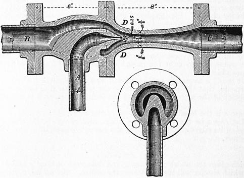
Fig. 62.
Fig. 63 shows the whole arrangement in a diagrammatic way. A is the reservoir which supplies the water that effects the pumping; B is the reservoir of water to be pumped; C is the reservoir into which the water is pumped.
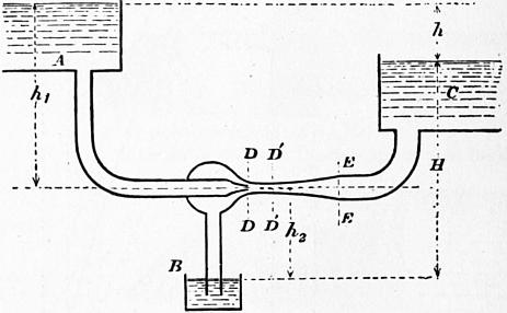
Fig. 63.
Discharge with Varying Head
§ 53. Flow from a Vessel when the Effective Head varies with the Time.—Various useful problems arise relating to the time of emptying and filling vessels, reservoirs, lock chambers, &c., where the flow is dependent on a head which increases or diminishes during the operation. The simplest of these problems is the case of filling or emptying a vessel of constant horizontal section.
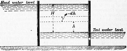
Fig. 64.
Time of Emptying or Filling a Vertical-sided Lock Chamber.—Suppose the lock chamber, which has a water surface of Ω square ft., is emptied through a sluice in the tail gates, of area ω, placed below the tail-water level. Then the effective head producing flow through the sluice is the difference of level in the chamber and tail bay. Let H (fig. 64) be the initial difference of level, h the difference of level after t seconds. Let −dh be the fall of level in the chamber during an interval dt. Then in the time dt the volume in the chamber is altered by the amount −Ωdh, and the outflow from the sluice in the same time is cω √(2gh) dt. Hence the differential equation connecting h and t is
cω √(2gh) dt + Ωh = 0.
For the time t, during which the initial head H diminishes to any other value h,
−{Ω/(cω √2g) } ∫hH dh/√h = ∫0t dt.
∴ t = 2Ω (√H − √h) / {cω √(2g)}
= (Ω/cω) {√(2H/g) − √(2h/g) }.
For the whole time of emptying, during which h diminishes from H to 0,
T = (Ω/cω) √(2H/g).
Comparing this with the equation for flow under a constant head, it will be seen that the time is double that required for the discharge of an equal volume under a constant head.
The time of filling the lock through a sluice in the head gates is exactly the same, if the sluice is below the tail-water level. But if the sluice is above the tail-water level, then the head is constant till the level of the sluice is reached, and afterwards it diminishes with the time.
Practical Use of Orifices in Gauging Water
§ 54. If the water to be measured is passed through a known orifice under an arrangement by which the constancy of the head is ensured, the amount which passes in a given time can be ascertained by the formulae already given. It will obviously be best to make the orifices of the forms for which the coefficients are most accurately determined; hence sharp-edged orifices or notches are most commonly used.
Water Inch.—For measuring small quantities of water circular sharp-edged orifices have been used. The discharge from a circular orifice one French inch in diameter, with a head of one line above the top edge, was termed by the older hydraulic writers a water-inch. A common estimate of its value was 14 pints per minute, or 677 English cub. ft. in 24 hours. An experiment by C. Bossut gave 634 cub. ft. in 24 hours (see Navier’s edition of Belidor’s Arch. Hydr., p. 212).
L. J. Weisbach points out that measurements of this kind would be made more accurately with a greater head over the orifice, and he proposes that the head should be equal to the diameter of the orifice. Several equal orifices may be used for larger discharges.
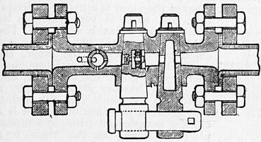
Fig. 65.
Pin Ferrules or Measuring Cocks.—To give a tolerably definite supply of water to houses, without the expense of a meter, a ferrule with an orifice of a definite size, or a cock, is introduced in the service-pipe. If the head in the water main is constant, then a definite quantity of water would be delivered in a given time. The arrangement is not a very satisfactory one, and acts chiefly as a check on extravagant use of water. It is interesting here chiefly as an example of regulation of discharge by means of an orifice. Fig. 65 shows a cock of this kind used at Zurich. It consists of three cocks, the middle one having the orifice of the predetermined size in a small circular plate, protected by wire gauze from stoppage by impurities in the water. The cock on the right hand can be used by the consumer for emptying the pipes. The one on the left and the measuring cock are connected by a key which can be locked by a padlock, which is under the control of the water company.
§ 55. Measurement of the Flow in Streams.—To determine the quantity of water flowing off the ground in small streams, which is available for water supply or for obtaining water power, small temporary weirs are often used. These may be formed of planks supported by piles and puddled to prevent leakage. The measurement of the head may be made by a thin-edged scale at a short distance behind the weir, where the water surface has not begun to slope down to the weir and where the velocity of approach is not high. The measurements are conveniently made from a short pile driven into the bed of the river, accurately level with the crest of the weir (fig. 66). Then if at any moment the head is h, the discharge is, for a rectangular notch of breadth b,
Q = 2⁄3 cbh √2gh
where c = 0.62; or, better, the formula in § 42 may be used.
Gauging weirs are most commonly in the form of rectangular notches; and care should be taken that the crest is accurately horizontal, and that the weir is normal to the direction of flow of the stream. If the planks are thick, they should be bevelled (fig. 67), and then the edge may be protected by a metal plate about 1⁄10th in. thick to secure the requisite accuracy of form and sharpness of edge. In permanent gauging weirs, a cast steel plate is sometimes used to form the edge of the weir crest. The weir should be large enough to discharge the maximum volume flowing in the stream, and at the same time it is desirable that the minimum head should not be too small (say half a foot) to decrease the effects of errors of measurement. The section of the jet over the weir should not exceed one-fifth the section of the stream behind the weir, or the velocity of approach will need to be taken into account. A triangular notch is very suitable for measurements of this kind.
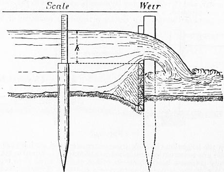
Fig. 66.
If the flow is variable, the head h must be recorded at equidistant intervals of time, say twice daily, and then for each 12-hour period the discharge must be calculated for the mean of the heads at the beginning and end of the time. As this involves a good deal of troublesome calculation, E. Sang proposed to use a scale so graduated as to read off the discharge in cubic feet per second. The lengths of the principal graduations of such a scale are easily calculated by putting Q = 1, 2, 3 ... in the ordinary formulae for notches; the intermediate graduations may be taken accurately enough by subdividing equally the distances between the principal graduations.
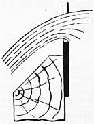
Fig. 67.
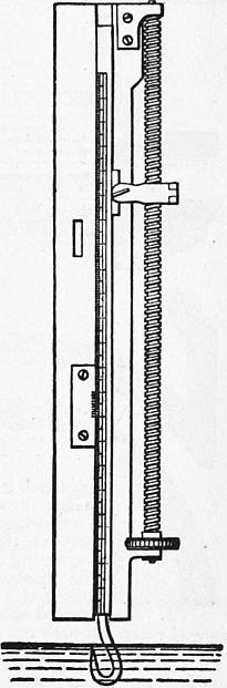
Fig. 68.
The accurate measurement of the discharge of a stream by means of a weir is, however, in practice, rather more difficult than might be inferred from the simplicity of the principle of the operation. Apart from the difficulty of selecting a suitable coefficient of discharge, which need not be serious if the form of the weir and the nature of its crest are properly attended to, other difficulties of measurement arise. The length of the weir should be very accurately determined, and if the weir is rectangular its deviations from exactness of level should be tested. Then the agitation of the water, the ripple on its surface, and the adhesion of the water to the scale on which the head is measured, are liable to introduce errors. Upon a weir 10 ft. long, with 1 ft. depth of water flowing over, an error of 1-1000th of a foot in measuring the head, or an error of 1-100th of a foot in measuring the length of the weir, would cause an error in computing the discharge of 2 cub. ft. per minute.
Hook Gauge.—For the determination of the surface level of water, the most accurate instrument is the hook gauge used first by U. Boyden of Boston, in 1840. It consists of a fixed frame with scale and vernier. In the instrument in fig. 68 the vernier is fixed to the frame, and the scale slides vertically. The scale carries at its lower end a hook with a fine point, and the scale can be raised or lowered by a fine pitched screw. If the hook is depressed below the water surface and then raised by the screw, the moment of its reaching the water surface will be very distinctly marked, by the reflection from a small capillary elevation of the water surface over the point of the hook. In ordinary light, differences of level of the water of .001 of a foot are easily detected by the hook gauge. If such a gauge is used to determine the heads at a weir, the hook should first be set accurately level with the weir crest, and a reading taken. Then the difference of the reading at the water surface and that for the weir crest will be the head at the weir.
§ 56. Modules used in Irrigation.—In distributing water for irrigation, the charge for the water may be simply assessed on the area of the land irrigated for each consumer, a method followed in India; or a regulated quantity of water may be given to each consumer, and the charge may be made proportional to the quantity of water supplied, a method employed for a long time in Italy and other parts of Europe. To deliver a regulated quantity of water from the irrigation channel, arrangements termed modules are used. These are constructions intended to maintain a constant or approximately constant head above an orifice of fixed size, or to regulate the size of the orifice so as to give a constant discharge, notwithstanding the variation of level in the irrigating channel.
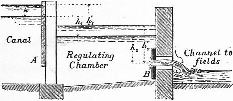
Fig. 69.
§ 57. Italian Module.—The Italian modules are masonry constructions, consisting of a regulating chamber, to which water is admitted by an adjustable sluice from the canal. At the other end of the chamber is an orifice in a thin flagstone of fixed size. By means of the adjustable sluice a tolerably constant head above the fixed orifice is maintained, and therefore there is a nearly constant discharge of ascertainable amount through the orifice, into the channel leading to the fields which are to be irrigated.
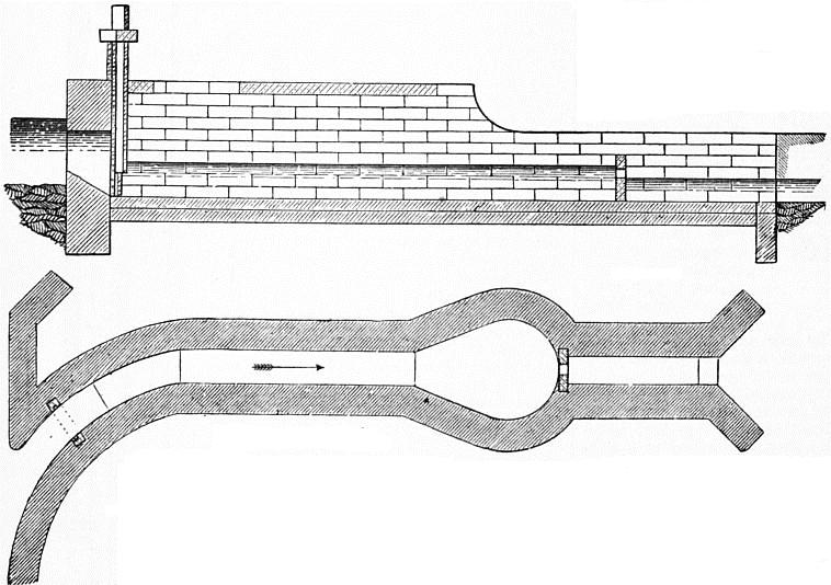
Fig. 70.—Scale 1⁄100.
In fig. 69, A is the adjustable sluice by which water is admitted to the regulating chamber, B is the fixed orifice through which the water is discharged. The sluice A is adjusted from time to time by the canal officers, so as to bring the level of the water in the regulating chamber to a fixed level marked on the wall of the chamber. When adjusted it is locked. Let ω1 be the area of the orifice through the sluice at A, and ω2 that of the fixed orifice at B; let h1 be the difference of level between the surface of the water in the canal and regulating chamber; h2 the head above the centre of the discharging orifice, when the sluice has been adjusted and the flow has become steady; Q the normal discharge in cubic feet per second. Then, since the flow through the orifices at A and B is the same,
Q = c1ω1 √(2gh1) = c2ω2 √(2gh2),
where c1 and c2 are the coefficients of discharge suitable for the two orifices. Hence
c1ω1 / c2ω2 = √(h2/h1).
If the orifice at B opened directly into the canal without any intermediate regulating chamber, the discharge would increase for a given change of level in the canal in exactly the same ratio. Consequently the Italian module in no way moderates the fluctuations of discharge, except so far as it affords means of easy adjustment from time to time. It has further the advantage that the cultivator, by observing the level of the water in the chamber, can always see whether or not he is receiving the proper quantity of water.
On each canal the orifices are of the same height, and intended to work with the same normal head, the width of the orifices being varied to suit the demand for water. The unit of discharge varies on different canals, being fixed in each case by legal arrangements. Thus on the Canal Lodi the unit of discharge or one module of water is the discharge through an orifice 1.12 ft. high, 0.12416 ft. wide, with a head of 0.32 ft. above the top edge of the orifice, or .88 ft. above the centre. This corresponds to a discharge of about 0.6165 cub. ft. per second.
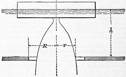
Fig. 71.
In the most elaborate Italian modules the regulating chamber is arched over, and its dimensions are very exactly prescribed. Thus in the modules of the Naviglio Grande of Milan, shown in fig. 70, the measuring orifice is cut in a thin stone slab, and so placed that the discharge is into the air with free contraction on all sides. The adjusting sluice is placed with its sill flush with the bottom of the canal, and is provided with a rack and lever and locking arrangement. The covered regulating chamber is about 20 ft. long, with a breadth 1.64 ft. greater than that of the discharging orifice. At precisely the normal level of the water in the regulating chamber, there is a ceiling of planks intended to still the agitation of the water. A block of stone serves to indicate the normal level of the water in the chamber. The water is discharged into an open channel 0.655 ft. wider than the orifice, splaying out till it is 1.637 ft. wider than the orifice, and about 18 ft. in length.
§ 58. Spanish Module.—On the canal of Isabella II., which supplies water to Madrid, a module much more perfect in principle than the Italian module is employed. Part of the water is supplied for irrigation, and as it is very valuable its strict measurement is essential. The module (fig. 72) consists of two chambers one above the other, the upper chamber being in free communication with the irrigation canal, and the lower chamber discharging by a culvert to the fields. In the arched roof between the chambers there is a circular sharp-edged orifice in a bronze plate. Hanging in this there is a bronze plug of variable diameter suspended from a hollow brass float. If the water level in the canal lowers, the plug descends and gives an enlarged opening, and conversely. Thus a perfectly constant discharge with a varying head can be obtained, provided no clogging or silting of the chambers prevents the free discharge of the water or the rise and fall of the float. The theory of the module is very simple. Let R (fig. 71) be the radius of the fixed opening, r the radius of the plug at a distance h from the plane of flotation of the float, and Q the required discharge of the module. Then
Q = cπ (R2 − r2) √(2gh).
Taking c = 0.63,
Q = 15.88 (R2 − r2) √h;
r = √ {R2 − Q/15.88 √h}.
Choosing a value for R, successive values of r can be found for different values of h, and from these the curve of the plug can be drawn. The module shown in fig. 72 will discharge 1 cubic metre per second. The fixed opening is 0.2 metre diameter, and the greatest head above the fixed orifice is 1 metre. The use of this module involves a great sacrifice of level between the canal and the fields. The module is described in Sir C. Scott-Moncrieff’s Irrigation in Southern Europe.
§ 59. Reservoir Gauging Basins.—In obtaining the power to store the water of streams in reservoirs, it is usual to concede to riparian owners below the reservoirs a right to a regulated supply throughout the year. This compensation water requires to be measured in such a way that the millowners and others interested in the matter can assure themselves that they are receiving a proper quantity, and they are generally allowed a certain amount of control as to the times during which the daily supply is discharged into the stream.
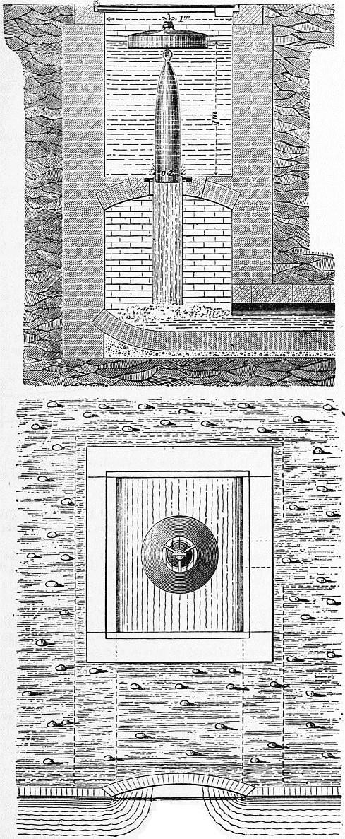
Fig. 72.
Fig. 74 shows an arrangement designed for the Manchester water works. The water enters from the reservoir at chamber A, the object of which is to still the irregular motion of the water. The admission is regulated by sluices at b, b, b. The water is discharged by orifices or notches at a, a, over which a tolerably constant head is maintained by adjusting the sluices at b, b, b. At any time the millowners can see whether the discharge is given and whether the proper head is maintained over the orifices. To test at any time the discharge of the orifices, a gauging basin B is provided. The water ordinarily flows over this, without entering it, on a floor of cast-iron plates. If the discharge is to be tested, the water is turned for a definite time into the gauging basin, by suddenly opening and closing a sluice at c. The volume of flow can be ascertained from the depth in the gauging chamber. A mechanical arrangement (fig. 73) was designed for securing an absolutely constant head over the orifices at a, a. The orifices were formed in a cast-iron plate capable of sliding up and down, without sensible leakage, on the face of the wall of the chamber. The orifice plate was attached by a link to a lever, one end of which rested on the wall and the other on floats f in the chamber A. The floats rose and fell with the changes of level in the chamber, and raised and lowered the orifice plate at the same time. This mechanical arrangement was not finally adopted, careful watching of the sluices at b, b, b, being sufficient to secure a regular discharge. The arrangement is then equivalent to an Italian module, but on a large scale.