VOLUME XII SLICE VII Gyantse to Hallel (continued 3)
Reading edition
CRμ sin θ = CR2 sin 23½° /26000 × 365,
(5)
one 12 millionth part of ½CR2, the rotation energy of the earth.
5. If the preponderance is absent, by making the C·G coincide with O, and if Aμ is insensible compared with G′,
N = −G′μ sin θ,
(1)
the formula which suffices to explain most gyroscopic action.
Thus a carriage running round a curve experiences, in consequence Gyroscopic action of railway wheels. of the rotation of the wheels, an increase of pressure Z on the outer track, and a diminution Z on the inner, giving a couple, if a is the gauge,
Za = G′μ,
(2)
tending to help the centrifugal force to upset the train; and if c is the radius of the curve, b of the wheels, C their moment of inertia, and v the velocity of the train,
μ = v/c, G′ = Cv/b,
(3)
Z = Cv2/abc (dynes),
(4)
so that Z is the fraction C/Mab of the centrifugal force Mv2/c, or the fraction C/Mh of its transference of weight, with h the height of the centre of gravity of the carriage above the road. A Brennan carriage on a monorail would lean over to the inside of the curve at an angle α, given by
tan α = G′μ/gMh = G′v/gMhc.
(6)
The gyroscopic action of a dynamo, turbine, and other rotating machinery on a steamer, paddle or screw, due to its rolling and pitching, can be evaluated in a similar elementary manner (Worthington, Dynamics of Rotation), and Schlick’s gyroscopic apparatus is intended to mitigate the oscillation.
6. If the axis OC in fig. 4 is inclined at an angle α to the vertical, the equation (2) § 4 becomes
N = sin θ (Aμ2 cos θ − G′μ) + gMh sin (α − θ).
(1)
Suppose, for instance, that OC is parallel to the earth’s axis, and that the frame is fixed in the meridian; then α is the co-latitude, and μ is the angular velocity of the earth, the square of which may be neglected; so that, putting N = 0, α − θ = E,
gMh sin E − G′μ sin (α − E) = 0,
(2)
tan E = G′μ sin α ≈ G′μ sin α.
gMh + G′μ cos α gMh
(3)
This is the theory of Gilbert’s barogyroscope, described in Appell’s Mécanique rationnelle, ii. 387: it consists essentially of a rapidly The barogyroscope. rotated fly-wheel, mounted on knife-edges by an axis perpendicular to its axis of rotation and pointing east and west; spun with considerable angular momentum G′, and provided with a slight preponderance Mh, it should tilt to an angle E with the vertical, and thus demonstrate experimentally the rotation of the earth.
In Foucault’s gyroscope (Comptes rendus, 1852; Perry, p. 105) Foucault’s gyroscope. the preponderance is made zero, and the axis points to the pole, when free to move in the meridian.
Generally, if constrained to move in any other plane, the axis seeks the position nearest to the polar axis, like a dipping needle with respect to the magnetic pole. (A gyrostatic working model of the magnetic compass, by Sir W. Thomson. British Association Report, Montreal, 1884. A. S. Chessin, St Louis Academy of Science, January 1902.)
A spinning top with a polished upper plane surface will provide an artificial horizon at sea, when the real horizon is obscured. The first instrument of this kind was constructed by Serson, and is described in the Gentleman’s Magazine, Gyroscopic horizon. vol. xxiv., 1754; also by Segner in his Specimen theoriae turbinum (Halae, 1755). The inventor was sent to sea by the Admiralty to test his instrument, but he was lost in the wreck of the “Victory,” 1744. A copy of the Serson top, from the royal collection, is now in the Museum of King’s College, London. Troughton’s Nautical Top (1819) is intended for the same purpose.
The instrument is in favour with French navigators, perfected by Admiral Fleuriais (fig. 9); but it must be noticed that the horizon given by the top is inclined to the true horizon at the angle E given by equation (3) above; and if μ1 is the precessional angular velocity as given by (3) § 4, and T = 2π/μ, its period in seconds,
tan E = μ cos lat = T cos lat , or E = T cos lat ,
μ1 86400 8π
(4)
if E is expressed in minutes, taking μ = 2π/86400; thus making the true latitude E nautical miles to the south of that given by the top (Revue maritime, 1890; Comptes rendus, 1896).
This can be seen by elementary consideration of the theory above, for the velocity of the vector OC′ of the top due to the rotation of the earth is
μ·OC′ cos lat = gMh sin E = μ1·OC′ sin E,
sin E = μ cos lat, E = T cos lat ,
μ1 8π
(5)
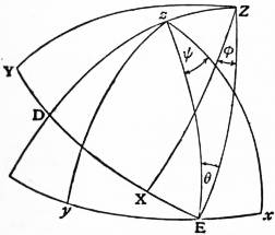
Fig. 11.
in which 8π can be replaced by 25, in practice; so that the Fleuriais gyroscopic horizon is an illustration of the influence of the rotation of the earth and of the need for its allowance.
7. In the ordinary treatment of the general theory of the gyroscope, the motion is referred to two sets of rectangular axes; the Euler’s coordinate angles. one Ox, Oy, Oz fixed in space, with Oz vertically upward and the other OX, OY, OZ fixed in the rotating wheel with OZ in the axis of figure OC.
The relative position of the two sets of axes is given by means of Euler’s unsymmetrical angles θ, φ, ψ, such that the successive turning of the axes Ox, Oy, Oz through the angles (i.) ψ about Oz, (ii.) θ about OE, (iii.) φ about OZ, brings them into coincidence with OX, OY, OZ, as shown in fig. 11, representing the concave side of a spherical surface.
The component angular velocities about OD, OE, OZ are
ψ sin θ, θ, φ + ψ cos θ;
(1)
so that, denoting the components about OX, OY, OZ by P, Q, R,
P = θ cos φ + ψ sin θ sin φ,
Q = −θ sin φ + ψ sin θ cos φ,
R = φ + ψ cos θ.
(2)
Consider, for instance, the motion of a fly-wheel of preponderance Mh, and equatoreal moment of inertia A, of which the axis OC is held in a light ring ZCX at a constant angle γ with OZ, while OZ is held by another ring zZ, which constrains it to move round the vertical Oz at a constant inclination θ with constant angular velocity μ, so that
θ = 0, ψ = μ;
(3)
P = μ sin θ sin φ, Q = μ sin θ cos φ, R = φ + μ cos θ.
(4)
With CXF a quadrant, the components of angular velocity and momentum about OF, OY, are
P cos γ − R sin γ, Q, and A (P cos γ − R sin γ), AQ,
(5)
so that, denoting the components of angular momentum of the fly-wheel about OC, OX, OY, OZ by K or G′, h1, h2, h3,
h1 = A (P cos γ − R sin γ) cos γ + K sin γ,
(6)
h2 = AQ,
(7)
h3 = −A (P cos γ − R sin γ) sin γ + K cos γ;
(8)
and the dynamical equation
dh3 − h1Q + h2P = N,
dt
(9)
with K constant, and with preponderance downward
N = gMh cos zY sin γ = gMh sin γ sin θ cos φ,
(10)
reduces to
A d2φ sin γ + Aμ2 sin γ sin2 θ sin φ cos φ
dt2
+ Aμ2 cos γ sin θ cos θ cos φ − (Kμ + gMh) sin θ cos φ = 0.
(11)
The position of relative equilibrium is given by
cos φ = 0, and sin φ = Kμ + gMh − Aμ2 cos γ cos θ .
Aμ2 sin γ sin θ
(12)
For small values of μ the equation becomes
A d2φ sin γ − (Kμ + gMh) sin θ cos φ = 0,
dt2
(13)
so that φ = ½π gives the position of stable equilibrium, and the period of a small oscillation is 2π √{A sin γ/(Kμ + gMh) sin θ}.
In the general case, denoting the periods of vibration about φ = ½π, −½π, and the sidelong position of equilibrium by 2π/(n1, n2, or n3), we shall find
n12 = sin θ { gMh + Kμ − Aμ2 cos (γ − θ) },
A sin γ
(14)
n22 = sin θ { −gMh − Kμ + Aμ2 cos (γ + θ) },
A sin γ
(15)
n3 = n1 n2/μ sin θ.
(16)
The first integral of (11) gives
½A ( dφ ) 2 sin γ + ½Aμ2 sin γ sin2 θ sin2 φ
dt
− Aμ2 cos γ sin θ cos θ sin φ + (Kμ + gMh) sin θ sin φ − H = 0,
(17)
and putting tan (¼π + ½φ) = z, this reduces to
dz n √Z
dt
(18)
where Z is a quadratic in z2, so that z is a Jacobian elliptic function of t, and we have
tan (¼π + ½φ) = C (tn, dn, nc, or cn) nt,
(19)
according as the ring ZC performs complete revolutions, or oscillates about a sidelong position of equilibrium, or oscillates about the stable position of equilibrium φ = ±½π.
Suppose Oz is parallel to the earth’s axis, and μ is the diurnal rotation, the square of which may be neglected, then if Gilbert’s barogyroscope of § 6 has the knife-edges turned in azimuth to make an angle β with E. and W., so that OZ lies in the horizon at an angle E·β·N., we must put γ = ½π, cos θ = sin α sin β; and putting φ = ½π − δ + E, where δ denotes the angle between Zz and the vertical plane Zζ through the zenith ζ,
sin θ cos δ = cos α, sin θ sin δ = sin α cos β;
(20)
so that equations (9) and (10) for relative equilibrium reduce to
gMh sin E = KQ = Kμ sin θ cos φ = Kμ sin θ sin (δ − E),
(21)
and will change (3) § 6 into
tan E = Kμ sin α cos β ,
gMh + Kμ cos α
(22)
a multiplication of (3) § 6 by cos β (Gilbert, Comptes rendus, 1882).
Changing the sign of K or h and E and denoting the revolutions/second of the gyroscope wheel by F, then in the preceding notation, T denoting the period of vibration as a simple pendulum,
tan E = Kμ sin α cos β = F sin α cos β ,
gMh − Kμ cos α 86400 A/T2C − F cos α
(23)
so that the gyroscope would reverse if it were possible to make F cos α > 86400 A/T2C (Föppl, Münch. Ber, 1904).
A gyroscopic pendulum is made by the addition to it of a fly-wheel, balanced and mounted, as in Gilbert’s barogyroscope, in a ring movable about an axis fixed in the pendulum, in the vertical plane of motion.
As the pendulum falls away to an angle θ with the upward vertical, and the axis of the fly-wheel makes an angle φ with the vertical plane of motion, the three components of angular momentum are
h1 = K cos φ, h2 = Aθ + K sin φ, h3 = Aφ,
(24)
where h3 is the component about the axis of the ring and K of the fly-wheel about its axis; and if L, M′, N denote the components of the couple of reaction of the ring, L may be ignored, while N is zero, with P = 0, Q = θ, R = 0, so that
M′ = h2 = Aθ + Kφ cos φ,
(25)
0 = h3 − h1θ = Aφ − Kθ cos φ.
(26)
For the motion of the pendulum, including the fly-wheel,
MK2θ = gMH sin θ − M′ = gMH sin θ − Aθ − Kφ cos φ.
(27)
If θ and φ remain small,
Aφ = Kθ, Aφ = K(θ − α),
(28)
(MK2 + A) θ + (K2/A) (θ − α) − gMHθ = 0;
(29)
so that the upright position will be stable if K2 > gMHA, or the rotation energy of the wheel greater than ½A/C times the energy acquired by the pendulum in falling between the vertical and horizontal position; and the vibration will synchronize with a simple pendulum of length
(MK2 + A) / [(K2/gA) − MH].
(30)
This gyroscopic pendulum may be supposed to represent a ship among waves, or a carriage on a monorail, and so affords an explanation of the gyroscopic action essential in the apparatus of Schlick and Brennan.
8. Careful scrutiny shows that the steady motion of a top is not steady absolutely; it reveals a small nutation General motion of the top. superposed, so that a complete investigation requires a return to the equations of unsteady motion, and for the small oscillation to consider them in a penultimate form.
In the general motion of the top the vector OH of resultant angular momentum is no longer compelled to lie in the vertical plane COC′ (fig. 4), but since the axis Oh of the gravity couple is always horizontal, H will describe a curve in a fixed horizontal plane through C. The vector OC′ of angular momentum about the axis will be constant in length, but vary in direction; and OK will be the component angular momentum in the vertical plane COC′, if the planes through C and C′ perpendicular to the lines OC and OC′ intersect in the line KH; and if KH is the component angular momentum perpendicular to the plane COC′, the resultant angular momentum OH has the three components OC′, C′K, KH, represented in Euler’s angles by
KH = A dθ/dt, C′K = A sin θd ψ/dt, OC′ = G′.
(1)
Drawing KM vertical and KN parallel to OC′, then
KM = A dψ/dt, KN = CR − A cos θ dψ/dt = (C − A) R + A dφ/dt
(2)
so that in the spherical top, with C = A, KN = A dφ/dt.
The velocity of H is in the direction KH perpendicular to the plane COC′, and equal to gMh sin θ or An2 sin θ, so that if a point in the axis OC′ at a distance An2 from O is projected on the horizontal plane through C in the point P on CK, the curve described by P, turned forwards through a right angle, will be the hodograph of H; this is expressed by
An2 sin θ e(ψ + 1/2π)i = iAn2 sin θ eψi = d (ρeῶi)
dt
(3)
where ρeῶi is the vector CH; and so the curve described by P and the motion of the axis of the top is derived from the curve described by H by a differentiation.
Resolving the velocity of H in the direction CH,
d·CH/dt = An2 sin θ sin KCH = An2 sin θ KH/CH,
(4)
d·½CH2/dt = A2n2sin θ dθ/dt.
(5)
and integrating
½CH2 = A2n2 (E − cos θ),
(6)
½OH2 = A2n2 (F − cos θ),
(7)
½C′H2 = A2n2 (D − cos θ),
(8)
where D, E, F are constants, connected by
F = E + G2/2A2n2 = D + G′2/2A2n2.
(9)
Then
KH2 = OH2 − OK2,
(10)
OK2 sin2 θ = CC′2 = G2 − 2GG′ cos θ + G′2,
(11)
A2 sin2 θ (dθ/dt)2 = 2A2n2 (F − cos θ) sin2 θ − G2 + 2GG′ cos θ − G′2;
(12)
and putting cos θ = z,
( dz ) = 2n2 (F − z) (1 − z2) − (G2 − 2GG′z + G′2) /A2
dt
(13)
= 2n2 (E − z) (1 − z2) − (G′ − Gz)2 /A2 = 2n2 (D − z) (1 − z2) − (G − G′z)2 /A2 = 2n2 Z suppose.
Denoting the roots of Z = 0 by z1, z2, z3, we shall have them arranged in the order
z1 > 1 > z2 > z > z3 > −1.
(14)
(dz/dt)2 = 2n2 (z1 − z) (z2 − z) (z − z3).
(15)
nt = ∫ zz3 dz/ √(2Z),
(16)
an elliptic integral of the first kind, which with
m = n √ z1 − z3 , κ2 = z2 − z3 ,
2 z1 − z2
(17)
can be expressed, when normalized by the factor √(z1 − z3)/2, by the inverse elliptic function in the form
mt = ∫ zz3 √ (z1 − z3) dz
√ [4 (z1 − z) (z2 − z) (z − z3)]
= sn−1 √ z − z3 = cn−1 √ z2 − z = dn−1 √ z1 − z .
z2 − z3 z2 − z3 z1 − z3
(18)
z − z3 = (z2 − z3) sn2mt, z2 − z = (z2 − z3) cn2mt, z1 − z = (z1 − z3) dn2mt.
(19)
z = z2sn2mt + z3cn2mt.
(20)
Interpreted dynamically, the axis of the top keeps time with the beats of a simple pendulum of length
L = l/½ (z1 − z3),
(21)
suspended from a point at a height ½ (z1 + z3)l above O, in such a manner that a point on the pendulum at a distance
½ (z1 − z3) l = l2/L
(22)
from the point of suspension moves so as to be always at the same level as the centre of oscillation of the top.
The polar co-ordinates of H are denoted by ρ, ῶ in the horizontal plane through C; and, resolving the velocity of H perpendicular to CH,
ρdῶ/dt = An2 sin θ cos KCH.
(23)
ρ2dῶ/dt = An2 sin θ·CK = An2 (G′ − G cos θ)
(24)
ῶ = ½ ∫ G′ − Gz dt = ∫ z3 (G′ − Gz) / 2An dz ,
E − z A E − z √ (2Z)
(25)
an elliptic integral, of the third kind, with pole at z = E; and then
ῶ − ψ = KCH = tan−1 KH/CH
= tan−1 A sin θ dθ/dt = tan−1 √ (2Z) ,
G′ − G cos θ (G′ − Gz) / An
(26)
which determines ψ.
Otherwise, from the geometry of fig. 4,
C′K sin θ = OC − OC′ cos θ,
(27)
A sin2 θ dψ/dt = G − G′ cos θ,
(28)
ψ = ∫ G − G′z dt = ½ ∫ G − G′ dt + ½ ∫ G + G′ dt ,
1 − z2 A 1 − z A 1 + z A
(29)
the sum of two elliptic integrals of the third kind, with pole at z = ±1; and the relation in (25) (26) shows the addition of these two integrals into a single integral, with pole at z = E.
The motion of a sphere, rolling and spinning in the interior of a spherical bowl, or on the top of a sphere, is found to be of the same character as the motion of the axis of a spinning top about a fixed point.
The curve described by H can be identified as a Poinsot herpolhode, that is, the curve traced out by rolling a quadric surface with centre fixed at O on the horizontal plane through C; and Darboux has shown also that a deformable hyperboloid made of the generating lines, with O and H at opposite ends of a diameter and one generator fixed in OC, can be moved so as to describe the curve H; the tangent plane of the hyperboloid at H being normal to the curve of H; and then the other generator through O will coincide in the movement with OC′, the axis of the top; thus the Poinsot herpolhode curve H is also the trace made by rolling a line of curvature on an ellipsoid confocal to the hyperboloid of one sheet, on the plane through C.
Kirchhoff’s Kinetic Analogue asserts also that the curve of H is the projection of a tortuous elastica, and that the spherical curve of C′ is a hodograph of the elastica described with constant velocity.
Writing the equation of the focal ellipse of the Darboux hyperboloid through H, enlarged to double scale so that O is the centre,
x2/α2 + y2/β2 + z2/O = 1,
(30)
with α2 + λ, β2 + λ, λ denoting the squares of the semiaxes of a confocal ellipsoid, and λ changed into μ and ν for a confocal hyperboloid of one sheet and of two sheets.
λ > 0 > μ > −β2 > ν > −α2,
(31)
then in the deformation of the hyperboloid, λ and ν remain constant at H; and utilizing the theorems of solid geometry on confocal quadrics, the magnitudes may be chosen so that
α2 + λ + β2 + μ + ν = OH2 = ½k2 (F − z) = ρ2 + OC2.
(32)
α2 + μ = ½k2 (z1 − z) = ρ2 − ρ12,
(33)
β2 + μ = ½k2 (z2 − z) = ρ2 − ρ22,
(34)
μ = ½k2 (z3 − z) = ρ2 − ρ32,
(35)
ρ12 < 0 < ρ22 < ρ2 < ρ32,
(36)
F = z1 + z2 + z3,
(37)
λ − 2μ + ν = k2z, λ − ν = k2,
(38)
λ − μ = 1 + z , μ − ν = 1 − z
λ − ν 2 λ − ν 2
(39)
with z = cos θ, θ denoting the angle between the generating lines through H; and with OC = δ, OC′ = δ′, the length k has been chosen so that in the preceding equations
δ/k = G/2An, δ′/k = G′/2An;
(40)
and δ, δ′, k may replace G, G′, 2An; then
2Z = 1 ( dθ ) 2 = 4KH2 ,
1 − z2 n2 dt k2
(41)
while from (33-39)
2Z = 4 (α2 + μ) (β2 + μ) μ ,
1 − z2 k2 (μ − λ) (μ − ν)
(42)
which verifies that KH is the perpendicular from O on the tangent plane of the hyperboloid at H, and so proves Darboux’s theorem.
Planes through O perpendicular to the generating lines cut off a constant length HQ = δ, HQ′ = δ′, so the line of curvature described by H in the deformation of the hyperboloid, the intersection of the fixed confocal ellipsoid λ and hyperboloid of two sheets ν, rolls on a horizontal plane through C and at the same time on a plane through C′ perpendicular to OC′.
Produce the generating line HQ to meet the principal planes of the confocal system in V, T, P; these will also be fixed points on the generator; and putting
(HV, HT, HP,)/HQ = D/(A, B, C,),
(43)
then
Ax2 + By2 + Cz2 = Dδ2
(44)
is a quadric surface with the squares of the semiaxes given by HV·HQ, HT·HQ, HP·HQ, and with HQ the normal line at H, and so touching the horizontal plane through C; and the direction cosines of the normal being
x/HV, y/HT, z/HP,
(45)
A2x2 + B2y2 + C2z2 = D2δ2,
(46)
the line of curvature, called the polhode curve by Poinsot, being the intersection of the quadric surface (44) with the ellipsoid (46).
There is a second surface associated with (44), which rolls on the plane through C′, corresponding to the other generating line HQ′ through H, so that the same line of curvature rolls on two planes at a constant distance from O, δ and δ′; and the motion of the top is made up of the combination. This completes the statement of Jacobi’s theorem (Werke, ii. 480) that the motion of a top can be resolved into two movements of a body under no force.
Conversely, starting with Poinsot’s polhode and herpolhode given in (44) (46), the normal plane is drawn at H, cutting the principal axes of the rolling quadric in X, Y, Z; and then
α2 + μ = x·OX, β2 + μ = y·OY, μ = z·OZ,
(47)
this determines the deformable hyperboloid of which one generator through H is a normal to the plane through C; and the other generator is inclined at an angle θ, the inclination of the axis of the top, while the normal plane or the parallel plane through O revolves with angular velocity dψ/dt.
The curvature is useful in drawing a curve of H; the diameter of curvature D is given by
D = dp2 = ½k2 sin3 θ , ½D = ¼k2 .
dp δ − δ′ p KM·KN
(48)
The curvature is zero and H passes through a point of inflexion when C′ comes into the horizontal plane through C; ψ will then be stationary and the curve described by C′ will be looped.
In a state of steady motion, z oscillates between two limits z2 and z3 which are close together; so putting z2 = z3 the coefficient of z in Z is
2Z1z3 + z23 = −1 + GG′ = −1 + (OM cos θ + ON) (OM + ON cos θ) ,
A2n2 OM·ON
(49)
2z1z3 = OM2 + ON2 cos θ, z1 = OM2 + ON2 ,
OM·ON 2OM·ON
(50)
2 (z1 − z3) = OM2 − 2OM·ON cos θ + ON2 = MN2 .
OM·ON OM·ON
(51)
With z2 = z3, κ = 0, K = ½π; and the number of beats per second of the axis is
m = n √ z1 − z3 = MN n ,
π π 2 √ (OM·ON) 2π
(52)
beating time with a pendulum of length
L = l = 4OM·ON l.
½ (z1 − z3) MN2
(53)
The wheel making R/2π revolutions per second,
beats/second = MN n = C · MN ,
revolutions/second √ (OM·ON) R A OC′
(54)
from (8) (9) § 3; and the apsidal angle is
μ ½π = Aμ · n ·½π = ON · 2√ (OM·ON) ·½π = ON π,
m An m √ (OM·ON) MN MN
(55)
and the height of the equivalent conical pendulum λ is given by
λ = g = n2 = OM = KC = OL ,
l lμ2 μ2 ON KC′ OC′
(56)
if OR drawn at right angles to OK cuts KC′ in R, and RL is drawn horizontal to cut the vertical CO in L; thus if OC2 represents l to scale, then OL will represent λ.
9. The gyroscope motion in fig. 4 comes to a stop when the rim of the wheel touches the ground; and to realize the motion when the axis is inclined at a greater angle with the upward vertical, the stalk is pivoted in fig. 8 in a lug screwed to the axle of a bicycle hub, fastened vertically in a bracket bolted to a beam. The wheel can now be spun by hand, and projected in any manner so as to produce a desired gyroscopic motion, undulating, looped, or with cusps if the stalk of the wheel is dropped from rest.
As the principal part of the motion takes place now in the neighbourhood of the lowest position, it is convenient to measure the angle θ from the downward vertical, and to change the sign of z and G.
Equation (18) § 8 must be changed to
mt = nt √ z3 − z1 = ∫ z3z √ (z3 − z1) dz ,
2 √ (4Z)
(1)
Z = (z − F) (1 − z2) − (G2 − 2GG′z + G′2) / 2A2n2 = (z − D) (1 − z2) − (G − G′z)2 / 2A2n2 = (z − E) (1 − z2) − (G′ − Gz)2 / 2A2n2 = (z3 − z) (z − z2) (z − z1),
(2)
1 > z3 > z > z2 > −1, D, E > z1,
(3)
z1 + z2 + z3 = F = D − G′2 / 2A2n2 = E − G2 / 2A2n2,
(4)
and expressed by the inverse elliptic function
mt = sn−1 √ z3 − z = cn−1 √ z − z2 = dn−1 √ z − z1 ,
z3 − z2 z3 − z2 z3 − z1
(5)
z = z2sn2mt + z3cn2mt, κ2 = (z3 − z2) / (z3 − z1).
(6)
Equation (25) and (29) § 8 is changed to
ῶ = ½ ∫ G′ − Gz dt = ½ ∫ G′ − GE dt − Gt ,
z − E A z − E A 2A
(7)
ψ = ∫ G′z − G dt = ½ ∫ G′ + G dt − ½ ∫ G′ − G dt ,
1 − z2 A 1 − z A 1 + z A
(8)
while ψ and ῶ change places in (26).
The Jacobian elliptic parameter of the third elliptic integral in (7) can be given by ν, where
v = ∫ z3E √ (z3 − z1) dz = ∫ z3z2 + ∫ z2E = K + (1 − f) Ki′,
√ (4Z)
(9)
where f is a real fraction,
(1 − f) K′ = ∫ z2E √ (z3 − z1) dz,
√ (−4Z)
(10)
fK′ = ∫ Ez1 √ (z3 − z1) dz,
√ (−4Z)
= sn−1 √ E − z1 = cn−1 √ z2 − E = dn−1 √ z3 − E ,
z2 − z1 z2 − z1 z3 − z1
(11)
with respect to the comodulus κ′.
Then, with z = E, and
2ZE = −{ (G′ − GE) / An}2,
(12)
if II denotes the apsidal angle of ῶ, and T the time of a single beat of the axle, up or down,
II + GT = ∫ z3z2 √ (−2ZE) dz ,
2A z − E √ (2Z)
= ½πf + Kznf K′,
(13)
in accordance with the theory of the complete elliptic integral of the third kind.
Interpreted geometrically on the deformable hyperboloid, flattened in the plane of the focal ellipse, if OQ is the perpendicular from the centre on the tangent HP, AOQ = amfK′, and the eccentric angle of P, measured from the minor axis, is am(1 − f) K′, the eccentricity of the focal ellipse being the comodulus κ′.
A point L is taken in QP such that
QL/OA = znfK′,
(14)
QV, QT, QP = OA (zs, zc, zd) fK′;
(15)
and with
mT = K, m/n = √ (z3 − z1) /2 = OA/k,
(16)
GT = G · k K = QH K,
2A 2An OA OA
(17)
II = ½πf + QL + QH K = ½πf + HL K.
OA OA
(18)
By choosing for f a simple rational fraction, such as ½, 1⁄3, ¼, 1⁄5, ... an algebraical case of motion can be constructed (Annals of Mathematics, 1904).
Thus with G′ − GE = 0, we have E = z1 or z2, never z3; f = 0 or 1; and P is at A or B on the focal ellipse; and then
ῶ = −pt, p = G/2A,
(19)
ψ + pt = tan−1 n√ (2Z) ,
2p (z − E)
(20)
sin θ exp (ψ + pt) i = i√ [(−z2 − z3) (z − z1)] + √ [(z3 − z) (z − z2)],
z1 = 1 + z2 z3 , √ −z2 − z3 = G = p = G′ , or
z2 + z3 2 2An n 2Anz1
(21)
sin θ exp (ψ + pt)i = i√ [(−z1 − z3) (z − z2)] + √ [(z3 − z) (z − z1)],
z2 = 1 + z1 z3 , √ −z1 − z3 = G = p = G′ .
z1 + z3 2 2An n 2Anz1
(22)
Thus z2 = 0 in (22) makes G′ = 0; so that if the stalk is held out horizontally and projected with angular velocity 2p about the vertical axis OC without giving any spin to the wheel, the resulting motion of the stalk is like that of a spherical pendulum, and given by
sin θ exp (ψ + pt)i = i √ ( 2p2 cos θ ) + √ ( sin2 θ − 2 p2 cos θ ),
n2 n2
= i sin α √ (sec α cos θ) + √ [(sec α + cos θ) (cos α − cos θ)],
(23)
if the axis falls in the lowest position to an angle α with the downward vertical.
With z3 = 0 in (21) and z2 = −cos β, and changing to the upward vertical measurement, the motion is given by
sin θ eψi = eint √ ½ cos β [√ (1 − cos β cos θ) + i√ (cos β cos θ − cos2 θ)],
(24)
and the axis rises from the horizontal position to a series of cusps; and the mean precessional motion is the same as in steady motion with the same rotation and the axis horizontal.
The special case of f = ½ may be stated here; it is found that
p exp (ῶ − pt) i = √ (1 + x) (κ − x) + i √ (1 − x) (κ + x) ,
a 2 2
(25)
ρ2 = a2 (κ − x2),
(26)
½λ2 sin θ exp (ψ − pt) i = (L − 1 + κ − x) √ (1 − x) (κ + x
2
+ i (L − 1 + κ + x) √ (1 + x) (κ − x) ,
2
(27)
L = ½ (1 − κ) + λp/n,
(28)
so that p = 0 and the motion is made algebraical by taking L = ½ (1 − κ).
The stereoscopic diagram of fig. 12 drawn by T. I. Dewar shows these curves for κ = 15⁄17, 3⁄5, and 1⁄3 (cusps).
10. So far the motion of the axis OC’ of the top has alone been considered; for the specification of any point of the body, Euler’s third angle φ must be introduced, representing the angular displacement of the wheel with respect to the stalk. This is given by
dφ + cos θ dψ = R,
dt dt
(1)
d(φ + ψ) = ( 1 − C ) R + G′ + G ,
dt A A (1 + cos θ)
d(φ − ψ) = ( 1 − C ) R + G′ − G .
dt A A (1 − cos θ)
(2)
It will simplify the formulas by cancelling a secular term if we make C = A, and the top is then called a spherical top; OH becomes the axis of instantaneous angular velocity, as well as of resultant angular momentum.
When this secular term is restored in the general case, the axis OI of angular velocity is obtained by producing Q′H to I, making
HI = A − C , HI = A − C ,
Q′H C Q′I A
(3)
and then the four vector components OC′, C′K, KH, HI give a resultant vector OI, representing the angular velocity ω, such that
OI/Q′I = ω/R.
(4)
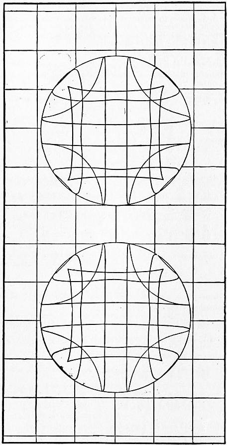
Fig. 12.
The point I is then fixed on the generating line Q′H of the deformable hyperboloid, and the other generator through I will cut the fixed generator OC of the opposite system in a fixed point O′, such that IO′ is of constant length, and may be joined up by a link, which constrains I to move on a sphere.
In the spherical top then,
½ (φ + ψ)= ∫ G′ + G dt , ½ (φ − ψ)= ∫ G′ − G dt
1 + z 2A 1 − z 2A
(5)
depending on the two elliptic integrals of the third kind, with pole at z = ±1; and measuring θ from the downward vertical, their elliptic parameters are:—
v1 = ∫ ∞1 √ (z3 − z1) dz = f1K′i,
√ (4Z)
(6)
v2 = ∫ −1−∞ √ (z3 − z1) dz K + (1 − f2) K′i,
√ (4Z)
(7)
f1K′ = ∫ ∞1 √ (z3 − z1) dz
√ ( −4Z)
= sn−1 √ z3 − z1 = cn−1 √ 1 − z3 = dn−1 √ 1 − z2 ,
1 − z1 1 − z1 1 − z1
(8)
(1 − f2) K′ = ∫ −1z1 √ (z3 − z1) dz
√ ( −4Z)
= sn−1 √ −1 − z1 = cn−1 √ 1 + z2 = dn−1 √ 1 + z3 .
z2 − z1 z2 − z1 z3 − z1
(9)
Then if v′ = K + (1 − f′)K′i is the parameter corresponding to z = D, we find
f = f2 − f1, f′ = f2 + f1,
(10)
v = v1 + v2, v′ = v1 − v2.
(11)
The most symmetrical treatment of the motion of any point fixed in the top will be found in Klein and Sommerfeld, Theorie des Kreisels, to which the reader is referred for details; four new functions, α, β, γ, δ, are introduced, defined in terms of Euler’s angles, θ, ψ, φ, by
α = cos ½θ exp ½ (φ + ψ) i,
(12)
β = i sin ½θ exp ½ (−φ + ψ) i,
(13)
γ = i sin ½θ exp ½ (φ − ψ) i,
(14)
δ = cos ½θ exp ½ (−φ − ψ) i.
(15)
Next Klein takes two functions or co-ordinates λ and Λ, defined by
λ = x + yi = r + z ,
r − z x − yi
(16)
and Λ the same function of X, Y, Z, so that λ, Λ play the part of stereographic representations of the same point (x, y, z) or (X, Y, Z) on a sphere of radius r, with respect to poles in which the sphere is intersected by Oz and OZ.
These new functions are shown to be connected by the bilinear relation
λ = αΛ + β , αδ − βγ = 1,
γΛ + δ
(17)
in accordance with the annexed scheme of transformation of co-ordinates—
Ξ Η Ζ
ξ α2 β2 2αβ
η γ2 δ2 2γδ
ζ αγ βδ αδ + βγ
where
ξ = x + yi, η = −x + yi, ζ = −z, Ξ = X + Yi, Η = −X + Yi, Ζ = −Z;
(18)
and thus the motion in space of any point fixed in the body defined by Λ is determined completely by means of α, β, γ, δ; and in the case of the symmetrical top these functions are elliptic transcendants, to which Klein has given the name of multiplicative elliptic functions; and
αδ = cos2 ½θ, βγ = −sin2 ½θ, αδ − βγ = 1, αδ + βγ = cos θ, √ ( −4αβγδ) = sin θ;
(19)
while, for the motion of a point on the axis, putting Λ = 0, or ∞,
λ = β/δ = i tan ½θeψi, or λ = α/γ = −i cot ½θeψi,
(20)
and
αβ = ½i sin θeψi, αγ = ½i sin θeψi,
(21)
giving orthogonal projections on the planes GKH, CHK; and
α dβ − dα β = n ρ eῶi,
dt dt k
(22)
the vectorial equation in the plane GKH of the herpolhode of H for a spherical top.
When f1 and f2 in (9) are rational fractions, these multiplicative elliptic functions can be replaced by algebraical functions, qualified by factors which are exponential functions of the time t; a series of quasi-algebraical cases of motion can thus be constructed, which become purely algebraical when the exponential factors are cancelled by a suitable arrangement of the constants.
Thus, for example, with f = 0, f′ = 1, f1 = ½, f2 = ½, as in (24) § 9, where P and P′ are at A and B on the focal ellipse, we have for the spherical top
(1 + cos θ) exp (φ + ψ − qt) i = √ (sec β − cos θ) √ (cos β − cos θ) + i (√ sec β + √ cos β) √ cos θ,
(23)
(1 − cos θ) exp (φ − ψ − q′t) i = √ (sec β − cos θ) √ (cos β − cos θ) + i (√sec β − √ cos β) √ cos θ,
(24)
q, q′ = n√ (2 sec β) ± n√ (2 cos β);
(25)
and thence α, β, γ, δ can be inferred.
The physical constants of a given symmetrical top have been denoted in § 1 by M, h, A, C, and l, n, T; to specify a given state of general motion we have G, G′ or CR, D, E, or F, which may be called the dynamical constants; or κ, v, w, v1, v2, or f, f′, f1, f2, the analytical constants; or the geometrical constants, such as α, β, δ, δ′, k of a given articulated hyperboloid.
There is thus a triply infinite series of a state of motion; the choice of a typical state can be made geometrically on the hyperboloid, flattened in the plane of the local ellipse, of which κ is the ratio of the semiaxes α and β, and am(1 − f) K′ is the eccentric angle from the minor axis of the point of contact P of the generator HQ, so that two analytical constants are settled thereby; and the point H may be taken arbitrarily on the tangent line PQ, and HQ′ is then the other tangent of the focal ellipse; in which case θ3 and θ2 are the angles between the tangents HQ, HQ′, and between the focal distances HS, HS′, and k2 will be HS·HS′, while HQ, HQ′ are δ, δ′. As H is moved along the tangent line HQ, a series of states of motion can be determined, and drawn with accuracy.
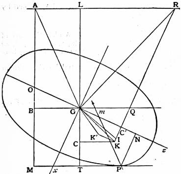
Fig. 13.
11. Equation (5) § 3 with slight modification will serve with the same notation for the steady rolling motion at a constant inclination α to the vertical of a body of revolution, such as a disk, hoop, wheel, cask, wine-glass, plate, dish, bowl, spinning top, gyrostat, or bicycle, on a horizontal plane, or a surface of revolution, as a coin in a conical lamp-shade.
The point O is now the intersection of the axis GC′ with the vertical through the centre B of the horizontal circle described by the centre of gravity, and through the centre M of the horizontal circle described by P, the point of contact (fig. 13). Collected into a particle at G, the body swings round the vertical OB as a conical pendulum, of height AB or GL equal to g/μ2 = λ, and GA would be the direction of the thread, of tension gM(GA/GL) dynes. The reaction with the plane at P will be an equal parallel force; and its moment round G will provide the couple which causes the velocity of the vector of angular momentum appropriate to the steady motion; and this moment will be gM·Gm dyne-cm. or ergs, if the reaction at P cuts GB in m.
Draw GR perpendicular to GK to meet the horizontal AL in R, and draw RQC′K perpendicular to the axis Gz, and KC perpendicular to LG.
The velocity of the vector GK of angular momentum is μ times the horizontal component, and
horizontal component /Aμ sin α = KC/KC′,
(1)
so that
gM·Gm = Aμ2 sin α(KC/KC′),
(2)
A = KC′ g Gm = GQ·Gm.
M KC μ2 sin α
(3)
The instantaneous axis of rotation of the case of a gyrostat would be OP; drawing GI parallel to OP, and KK′ parallel to OG, making tan K′GC′ = (A/C) tan IGC’1; then if GK represents the resultant angular momentum, K′K will represent the part of it due to the rotation of the fly-wheel. Thus in the figure for the body rolling as a solid, with the fly-wheel clamped, the points m and Q move to the other side of G. The gyrostat may be supposed swung round the vertical at the end of a thread PA′ fastened at A′ where Pm produced cuts the vertical AB, and again at the point where it crosses the axis GO. The discussion of the small oscillation superposed on the state of steady motion requisite for stability is given in the next paragraph.
12. In the theoretical discussion of the general motion General motion of a gyrostat rolling on a plane. of a gyrostat rolling on a horizontal plane the safe and shortest plan apparently is to write down the most general equations of motion, and afterwards to introduce any special condition.
Drawing through G the centre of gravity any three rectangular axes Gx, Gy, Gz, the notation employed is
u, v, w, the components of linear velocity of G;
p, q, r, the components of angular velocity about the axes;
h1, h2, h3, the components of angular momentum;
θ1, θ2, θ3, the components of angular velocity of the coordinate axes;
x, y, z, the co-ordinates of the point of contact with the horizontal plane;
X, Y, Z, the components of the reaction of the plane;
α, β, γ, the direction cosines of the downward vertical.
The geometrical equations, expressing that the point of contact is at rest on the plane, are
u − ry + qz = 0,
(1)
v − pz + rx = 0,
(2)
w − qx + py = 0.
(3)
The dynamical equations are
du/dt − θ3v + θ2w = gα + X/M,
(4)
dv/dt − θ1w + θ2u = gβ + Y/M,
(5)
dw/dt − θ2u + θ1v = gγ + Z/M,
(6)
and
dh1/dt − θ3h2 + θ2h3 = yZ − zY,
(7)
dh2/dt − θ1h3 + θ3h1 = zX − xZ,
(8)
dh3/dt − θ2h1 + θ1h2 = xY − yX.
(9)
In the special case of the gyrostat where the surface is of revolution round Gz, and the body is kinetically symmetrical about Gz, we take Gy horizontal and Gzx through the point of contact so that y = 0; and denoting the angle between Gz and the downward vertical by θ (fig. 13)
α = sin θ, β = 0, γ = cos θ.
(10)
The components of angular momentum are
h1 = Ap, h2 = Aq, h3 = Cr + K,
(11)
where A, C denote the moment of inertia about Gx, Gz, and K is the angular momentum of a fly-wheel fixed in the interior with its axis parallel to Gz; K is taken as constant during the motion.
The axis Gz being fixed in the body,
θ1 = p, θ2 = q = −dθ/dt, θ3 = p cot θ.
(12)
With y = 0, (1), (2), (3) reduce to
u = −qz, v = pz − rx, w = qx;
(13)
and, denoting the radius of curvature of the meridian curve of the rolling surface by ρ,
dx = ρ cos θ dθ = −q ρ cos θ, dz = −ρ sin θ dθ = q ρ sin θ;
dt dt dt dt
(14)
so that
du = − dq z − q2ρ sin θ,
dt dt
(15)
dv = dp z − dr x + pqρ sin θ + qrρ sin θ,
dt dt dt
(16)
dw = dq x − q2ρ cos θ.
dt dt
(17)
The dynamical equations (4)...(9) can now be reduced to
X = − dq z − p2z cotθ + q2 (x − ρ sin θ) + prx cot θ − g sin θ,
M dt
(18)
Y = dp z − dr x − pq (x + z cot θ − ρ sin θ) + qrp cos θ,
M dt dt
(19)
Z = dq x + q2 (z − ρ cos θ) + p2z − prx − g cos θ,
M dt
(20)
−zY = A dp − Apq cot θ + qh3,
dt
(21)
−zX − xZ = A dq + Ap2 cot θ − ph3,
dt
xY = dh3 = C dr = −Cq d .
dt dt dθ
(23)
Eliminating Y between (19) and (23),
( C + x2 ) dr − xz dp + pqx (x + z cot θ − ρ sin θ) − qrxρ cos θ = 0,
M dt dt
(24)
( C + x2 ) dr − xz dp − px (x + z cot θ − ρ sin θ) + rxρ cos θ = 0.
M dθ dθ
(A)
Eliminating Y between (19) and (21)
( A + z2 ) dp − xz dr − A pq cot θ + q h3
M dt dt M M
− pqz (x + z cot θ − ρ sin θ) + qrzρ cos θ = 0,
(25)
−xz dr + ( A + z2 ) dp + A p cot θ − h3
dθ M dθ M M
+ pz (x + z cot θ − ρ sin θ) + rzρ cos θ = 0.
(B)
In the special case of a gyrostat rolling on the sharp edge of a circle passing through G, z = 0, ρ = 0, (A) and (B) reduce to
p = ( C + 1 ) dr = ( 1 + 1 ) dh3 ,
Mx2 dθ Mx2 C dθ
(26)
dp + p cot θ = h3 , d·p sin θ = h3 sin θ ;
dθ A dθ A
(27)
d2h3 + dh3 cot θ = CMx2 h3,
dθ2 dθ A (Mx2 + C)
(28)
a differential equation of a hypergeometric series, of the form of Legendre’s zonal harmonic of fractional order n, given by
n (n + 1) = CMx2 / A (Mx2 + C).
(29)
For a sharp point, x = 0, ρ = 0, and the previous equations are obtained of a spinning top.
The elimination of X and Z between (18) (20) (22), expressed symbolically as
(22) − z(18) + x(20) = 0,
(30)
gives
( A + x2 + z2 ) dq − p h3 + ( A + z2 ) p2 cot θ + p2xz
M dt M M
+ q2ρ (x cos θ − z sin θ) − prx (x + z cot θ) − g (x cos θ − z sin θ) = 0,
(C)
and this combined with (A) and (B) will lead to an equation the integral of which is the equation of energy.
13. The equations (A) (B) (C) are intractable in this general form; but the restricted case may be considered when the axis moves in steady motion at a constant inclination α to the vertical; and the stability is secured if a small nutation of the axis can be superposed.
It is convenient to put p = Ω sin θ, so that Ω is the angular velocity of the plane Gzx about the vertical; (A) (B) (C) become
( C + x2 ) dr − xz sin θ dΩ
M dθ dθ
− Ωx (x sin θ − 2z cos θ − ρ sin2 θ) + rxρ cos θ = 0,
(A*)
−xz dr + ( A + z2 ) sin θ dΩ − h3 + 2Ω ( A + z2 ) cos θ
dθ M dθ M M
+ Ωz sin θ (x − ρ sin θ) − rzρ cos θ = 0,
(B*)
( A + x2 + z2 ) dq + q2p (x cos θ − z sin θ) − Ω h3 sin θ
M dt M
+ Ω2 ( A + z2 ) sin θ cos θ + Ω2xz sin2 θ
M
− Ωrx (x sin θ + z cos θ) − g (x cos θ − z sin θ) = 0.
(C*)
The steady motion and nutation superposed may be expressed by
θ = α + L, sin θ = sin α + L cos α, cos θ = cos α − L sin α, Ω = μ + N, r = R + Q,
(1)
where L, N, Q are small terms, involving a factor enti, to express the periodic nature of the nutation; and then if a, c denote the mean value of x, z, at the point of contact
x = a + Lρ cos α, z = c − Lρ sin α,
(2)
x sin θ + z cos θ = a sin α + c cos α + L (a cos α − c sin α),
(3)
x cos θ − z sin θ = a cos α − c sin α − L (a sin α + c cos α − ρ).
(4)
Substituting these values in (C*) with dq/dt = −d2θ/dt2 = n2L, and ignoring products of the small terms, such as L2, LN, ...
( A + a2 + c2 ) Ln2 − (μ + N) ( CR + K + CQ ) (sin α + L cos α)
M M M
+ (μ2 + 2μN) (A/M + c2 − 2Lρc sin α) (sin α cos α + L cos α) + (μ2 + 2μN) [ac − Lρ (a sin α − c sin α)] (sin2 α + L sin 2α) − (μ + N) (R + Q) (a + Lρcos α) [a sin α + c cos α + L (a cos α − c sin α)] − g (a cos α − c sin α) + gL (a sin α + c cos α − ρ) = 0,
(C**)
which is equivalent to
−μ CR + K sin α + μ2 ( A + c2 ) sin αcos α
M M
+ μ2 ac sin2 α − μRa (a sin α + c cos α) − g (a cos α − c sin α) = 0,
(5)
the condition of steady motion; and
DL + EQ + FN = 0,
(6)
where
D = ( A + a2 + c2 ) n2 − μ CK + K cos α − 2μ2ρc sin2 α cos α
M M
+ μ2 (A/M + c2) cos α − μ2ρ (a sin α − c cos α) sin2 α + μ2ac sin 2α − μRρ cos α (a sin α + c cos α) − μRa (a cos α − c sin α) + g (a sin α + c cos α − ρ),
(7)
E = −μ C sin α − μa (a sin α + c cos α),
M
(8)
F = − CR + K sin α + 2μ ( A + c2 ) sin α cos α
M M
+ 2μac sin2 α − Ra (a sin α + c cos α).
(9)
With the same approximation (A*) and (B*) are equivalent to
( C + a2 ) Q − ac sin α N − μa (a sin α + 2c cos α − ρ sin2 α) + Raρ cos α = 0,
M L L
(A**)
−ac Q + ( A + c2 ) sin α N − CR + K + 2μ ( A + c2 ) cos α
L M L M M
+ μc sin α (a − ρ sin α) − Rcρ cos α = 0.
(B**)
The elimination of L, Q, N will lead to an equation for the determination of n2, and n2 must be positive for the motion to be stable.
If b is the radius of the horizontal circle described by G in steady motion round the centre B,
b = v/μ = (cP − aR) / μ = c sin α − aR / μ,
(10)
and drawing GL vertically upward of length λ = g/μ2, the height of the equivalent conical pendulum, the steady motion condition may be written
(CR + K) μ sin α − μ2 sin α cos α = −gM (a cos α − c sin α)
+ M (μ2c sin α − μRa) (a sin α + c cos α)
= gM [bλ−1 (a sin α + c cos α) − a cos α + c sin α] = gM·PT,
(11)
LG produced cuts the plane in T.
Interpreted dynamically, the left-hand side of this equation represents the velocity of the vector of angular momentum about G, so that the right-hand side represents the moment of the applied force about G, in this case the reaction of the plane, which is parallel to GA, and equal to gM·GA/GL; and so the angle AGL must be less than the angle of friction, or slipping will take place.
Spinning upright, with α = 0, a = 0, we find F = 0, Q = 0, and
− CR + K + 2μ ( A + c2 ) − Rcp = 0,
M M
(12)
( A + c2 ) n2 = μ CR + K − μ2 ( A + c2 ) + μRρc − g (c − ρ),
M M M
(13)
( A + c2 ) 2 n2 = ¼ ( CK + R + Rcρ ) 2 − g ( A + c2 ) (c − ρ).
M M M
(14)
Thus for a top spinning upright on a rounded point, with K = 0, the stability requires that
R > 2k′√ {g (c − ρ)} / (k2 + cρ),
(15)
where k, k′ are the radii of gyration about the axis Gz, and a perpendicular axis at a distance c from G; this reduces to the preceding case of § 3 (7) when ρ = 0.
Generally, with α = 0, but a ± 0, the condition (A) and (B) becomes
( C + a2 ) Q = 2μac − Raρ,
M L
−ac Q = CR + K + Rcρ − 2μ ( A + a2 ),
L M M
(16)
so that, eliminating Q/L,
2 [( A + c2 )( C + a2 ) − a2c2 ] μ = ( C + a2 )( CR + K ) + C Rcρ,
M M M M M
(17)
the condition when a coin or platter is rolling nearly flat on the table.
Rolling along in a straight path, with α = ½π, c = 0, μ = 0, E = 0; and
N/L = (CR + K)/A,
(18)
D = ( A + a2 ) n2 + g (a − ρ),
M
F = − CR + K − Ra2,
M
(19)
N = − D = ( A + a2 ) n2 + g (a − ρ) M ,
L F ( C + a2 ) R + K M M
(20)
( A + a2 ) n2 = (CR + K) [( C + a2 ) R + K ] − g (a − ρ).
M A M M
(21)
Thus with K = 0, and rolling with velocity V = Ra, stability requires
V2 > a − ρ > ½ A a − ρ ,
2g 2C/A (C/Ma2 + 1) C C/Ma2 + 1
(22)
or the body must have acquired velocity greater than attained by rolling down a plane through a vertical height ½ (a − ρ) A/C.
On a sharp edge, with ρ = 0, a thin uniform disk or a thin ring requires
V2/2g > a/6 or a/8.
(23)
The gyrostat can hold itself upright on the plane without advance when R = 0, provided
K2/AM − g (a − ρ) is positive.
(24)
For the stability of the monorail carriage of § 5 (6), ignoring the rotary inertia of the wheels by putting C = 0, and replacing K by G′ the theory above would require
G′ ( aV + G′ ) > gh.
A A
For further theory and experiments consult Routh, Advanced Rigid Dynamics, chap. v., and Thomson and Tait, Natural Philosophy, § 345; also Bourlet, Traité des bicycles (analysed in Appell, Mécanique rationnelle, ii. 297, and Carvallo, Journal de l’école polytechnique, 1900); Whipple, Quarterly Journal of Mathematics, vol. xxx., for mathematical theories of the bicycle, and other bodies.
14. Lord Kelvin has studied theoretically and experimentally the vibration of a chain of stretched gyrostats (Proc. London Math. Soc., 1875; J. Perry, Spinning Tops, Gyrostatic chain. for a diagram). Suppose each gyrostat to be equivalent dynamically to a fly-wheel of axial length 2a, and that each connecting link is a light cord or steel wire of length 2l, stretched to a tension T.
Denote by x, y the components of the slight displacement from the central straight line of the centre of a fly-wheel; and let p, q, 1 denote the direction cosines of the axis of a fly-wheel, and r, s, 1 the direction cosines of a link, distinguishing the different bodies by a suffix.
Then with the previous notation and to the order of approximation required,
θ1 = −dq/dt, θ2 = dp/dt,
(1)
h1 = Aθ1, h2 = Aθ2, h3 = K,
(2)
to be employed in the dynamical equations
dh1 − θ3h2 + θ2h3 = L, ...
dt
(3)
in which θ3h1 and θ3h2 can be omitted.
For the kth fly-wheel
−Aqk + Kpk = Ta (qk − sk) + Ta (qk − sk+1),
(4)
Apk + Kqk = −Ta (pk − rk) − Ta (pk − rk+1);
(5)
and for the motion of translation
Mxk = T (rk+1 − rk), Myk = T (sk+1 − sk);
(6)
while the geometrical relations are
xk+1 − xk = a (pk+1 + pk) + 2lrk+1,
(7)
yk+1 − yk = a (qk+1 + qk) + 2lsk+1.
(8)
Putting
x + yi = w, p + qi = ω, r + si = σ,
(9)
these three pairs of equations may be replaced by the three equations
Aῶk − Kῶki + 2Taῶk − Ta (σk+1 + σk) = 0,
(10)
Mῶk − T (σk+1 − σk) = 0,
(11)
ωk+1 − ωk − a(ῶk+1 + ῶk − 2lσk+1) = 0.
(12)
For a vibration of circular polarization assume a solution
ωk, ῶk, σk = (L, P, Q) exp (nt + kc) i,
(13)
so that c/n is the time-lag between the vibration of one fly-wheel and the next; and the wave velocity is
U = 2 (a + l) n/c.
(14)
Then
P (−An2 + Kn + 2Ta) − QTa (eci + 1) = 0,
(15)
−LMn2 − QT (eci − 1) = 0,
(16)
L (eci − 1) − Pa (eci + 1) − 2Qleci = 0,
(17)
leading, on elimination of L, P, Q, to
cos c = (2 Ta + Kn − An2) (1 − Mn2l/T) − Mna2 ,
2Ta + Kn − An2 + Mna2
(18)
2 sin2 ½c = Mn2 2Ta (a + l) + KNl − An2l .
T 2Ta + Kn − An2 + Mn2a2
(19)
With K = 0, A = 0, this reduces to Lagrange’s condition in the vibration of a string of beads.
Putting
ρ = M/2 (a + l), the mass per unit length of the chain,
(20)
κ = K/2 (a + l), the gyrostatic angular momentum per unit length,
(21)
α = A/2 (a + l), the transverse moment of inertia per unit length,
(22)
1/2c = (a + l) n/U,
(23)
equation (19) can be written
{sin (a + l) n/U}2
= (a + l)2n2 ρ · Ta + κnl − αn2l ,
T Ta + κn (a + l) − αn2 (a + l) + ρn2a2 (a + l)
(24)
{ (a + l) n } 2
sin (a + l) n/U
= T · T + (κn − αn2) (1 + l/a) + ρn2a (a + l) .
ρ T + (κn − an2) l/a
(25)
In a continuous chain of such gyrostatic links, with a and l infinitesimal,
U2 = T { 1 + κn − αn2 }
ρ T + (κn − αn2 l/a)
(26)
for the vibration of helical nature like circular polarization.
Changing the sign of n for circular polarization in the opposite direction
U′2 = T { 1 − κn + αn2 }
ρ T − (κn + αn2 l/a)
(27)
In this way a mechanical model is obtained of the action of a magnetized medium on polarized light, κ representing the equivalent of the magnetic field, while α may be ignored as insensible (J. Larmor, Proc. Lond. Math. Soc., 1890; Aether and Matter, Appendix E).
We notice that U2 in (26) can be positive, and the gyrostatic chain stable, even when T is negative, and the chain is supporting a thrust, provided κn is large enough, and the thrust does not exceed
(κn − an2) (1 + l/a);
(28)
while U′2 in (27) will not be positive and the straight chain will be unstable unless the tension exceeds
(κn + αn2) (1 + l/a).
(29)
15. Gyrostat suspended by a Thread.—In the discussion of the small vibration of a single gyrostat fly-wheel about the vertical position when suspended by a single thread of length 2l = b, the suffix k can be omitted in the preceding equations of § 14, and we can write
Aῶ − Kῶi + Taῶ − Taσ = 0,
(1)
Mw + Tσ = 0, with T = gM,
(2)
w − aῶ − bσ = 0.
(3)
Assuming a periodic solution of these equations
w, ῶ, σ, = (L, P, Q) exp nti,
(4)
and eliminating L, P, Q, we obtain
(−An2 + Kn + gMa) (g − n2b) − gMn2a2 = 0,
(5)
and the frequency of a vibration in double beats per second is n/2π, where n is a root of this quartic equation.
For upright spinning on a smooth horizontal plane, take b = ∞ and change the sign of a, then
An2 − Kn + gMa = 0,
(6)
so that the stability requires
K2 > 4gAMa.
(7)
Here A denotes the moment of inertia about a diametral axis through the centre of gravity; when the point of the fly-wheel is held in a small smooth cup, b = 0, and the condition becomes
(A + Ma2) n2 − Kn + gMa = 0,
(8)
requiring for stability, as before in § 3,
K2 > 4g (A + M2) Ma.
(9)
For upright spinning inside a spherical surface of radius b, the sign of a must be changed to obtain the condition at the lowest point, as in the gyroscopic horizon of Fleuriais.
For a gyrostat spinning upright on the summit of a sphere of radius b, the signs of a and b must be changed in (5), or else the sign of g, which amounts to the same thing.
Denoting the components of horizontal displacement of the point of the fly-wheel by ξ, η, then
br = ξ, bs = η, bσ = ξ + ηi = λ (suppose),
(10)
ω = αῶ + λ.
(11)
If the point is forced to take the motion (ξ, η, ζ) by components of force X, Y, Z, the equations of motion become
−Aq + Kp = Ya − Zaq,
(12)
Ap + Kq = −Xa + Zap,
(13)
Mῶ = X + Yi, M (ζ − g) = Z;
(14)
so that
Aῶ − Kῶi + gMaῶ + Maw = Maῶζ,
(15)
or
(A + Ma2)ῶ − Kῶi + gMaῶ + Maλ = Maῶζ.
(16)
Thus if the point of the gyrostat is made to take the periodic motion given by λ = R exp nti, ζ = 0, the forced vibration of the axis is given by ῶ = P exp nti, where
P { −(A + Ma2) n2 + Kn + gMa} − RMn2a = 0;
(17)
and so the effect may be investigated on the Fleuriais gyroscopic horizon of the motion of the ship.
Suppose the motion λ is due to the suspension of the gyrostat from a point on the axis of a second gyrostat suspended from a fixed point.
Distinguishing the second gyrostat by a suffix, then λ = bῶ1, if b denotes the distance between the points of suspension of the two gyrostats; and the motion of the second gyrostat influenced by the reaction of the first, is given by
(A1 + M1h12)ῶ1 − K1ῶ1i
= −g (M1h1 + Mb) ῶ1 − b (X + Yi) = −g (M1h1 + Mb) ῶ1 − Mb(aῶ + λ);
(18)
so that, in the small vibration,
R { −(A1 + M1h12) n2 + K1n + g (M1h1 + Mb) } = Mn2b (aP + R),
b
(19)
R { −(A1 + M1h12 + Mb2) n2 + K1n + g (M1h1 + Mb)} − PMn2ab2 = 0.
(20)
Eliminating the ratio of P to R, we obtain
{ −(A + Ma2) n2 + Kn + gMa} × { −(A1 + M1h12 + Mb2) n2 + K1n + g (M1h1 + Mb)} − M2n4a2b2 = 0,
(21)
a quartic for n, giving the frequency n/2π of a fundamental vibration.
Change the sign of g for the case of the gyrostats spinning upright, one on the top of the other, and so realize the gyrostat on the top of a gyrostat described by Maxwell.
In the gyrostatic chain of § 14, the tension T may change to a limited pressure, and U2 may still be positive, and the motion stable; and so a motion is realized of a number of spinning tops, superposed in a column.
16. The Flexure Joint.—In Lord Kelvin’s experiment the gyrostats are joined up by equal light rods and short lengths of elastic wire with rigid attachment to the rod and case of a gyrostat, so as to keep the system still, and free from entanglement and twisting due to pivot friction of the fly-wheels.
When this gyrostatic chain is made to revolve with angular velocity n in relative equilibrium as a plane polygon passing through Oz the axis of rotation, each gyrostatic case moves as if its axis produced was attached to Oz by a flexure joint. The instantaneous axis of resultant angular velocity bisects the angle π − θ, if the axis of the case makes an angle θ with Oz, and, the components of angular velocity being n about Oz, and −n about the axis, the resultant angular velocity is 2n cos½ (π − θ) =2n sin½θ; and the components of this angular velocity are
(1) −2n sin ½θ sin ½θ = −n (1 − cos θ), along the axis, and
(2) −2n sin ½θ cos ½θ = −n sin θ, perpendicular to the axis of the case. The flexure joint behaves like a pair of equal bevel wheels engaging.
The component angular momentum in the direction Ox is therefore
L = −An sin θ cos θ − Cn (1 − cos θ) sin θ + K sin θ,
(3)
and Ln is therefore the couple acting on the gyrostat.
If α denotes the angle which a connecting link makes with Oz, and T denotes the constant component of the tension of a link parallel to Oz, the couple acting is
Ta cos θk (tan αk+1 + tan αk) − 2Tα sin θk,
(4)
which is to be equated to Ln, so that
−An2 sin θk cos θk − Cn (1 − cos θk) sin θk + Kn sin θk −Ta cos θk (tan αk+1 + tan αk) + 2Tα sin θk = 0.
(5)
In addition
Mn2xk + T (tan αk+1 − tan αk) = 0,
(6)
with the geometrical relation
xk+1 − xk − a (sin θk+1 + sin θk) − 2l sin αk+1 = 0.
(7)
When the polygon is nearly coincident with Oz, these equations can be replaced by
(−An2 + Kn + 2Ta) θk − Ta (αk+1 + αk) = 0,
(8)
Mn2xk + T (αk+1 − αk) = 0,
(9)
xk+1 − xk − a (θk+1 + θk) − 2lak = 0,
(10)
and the rest of the solution proceeds as before in § 14, putting
xk, θk, αk = (L, P, Q) exp cki.
(11)
A half wave length of the curve of gyrostats is covered when ck = π, so that π/c is the number of gyrostats in a half wave, which is therefore of wave length 2π (a + l)/c.
A plane polarized wave is given when exp cki is replaced by exp (nt + ck) i, and a wave circularly polarized when w, ῶ, σ of § 14 replace this x, θ, α.
Gyroscopic Pendulum.—The elastic flexure joint is useful for supporting a rod, carrying a fly-wheel, like a gyroscopic pendulum.
Expressed by Euler’s angles, θ, φ, ψ, the kinetic energy is
T = ½A (θ2 + sin2 θψ2) + ½C′ (1 − cos θ)2ψ2 + ½C (φ + ψ cos θ)2,
(12)
where A refers to rod and gyroscope about the transverse axis at the point of support, C′ refers to rod about its axis of length, and C refers to the revolving fly-wheel.
The elimination of ψ between the equation of conservation of angular momentum about the vertical, viz.
(13) A sin2 θψ − C′ (1 − cos θ) cos θψ + C(φ + ψ cos θ) cos θ = G, a constant, and the equation of energy, viz.
(14) T − gMh cos θ = H, a constant, with θ measured from the downward vertical, and
(15) φ + ψ cos θ = R, a constant, will lead to an equation for dθ/dt, or dz/dt, in terms of cos θ or z, the integral of which is of hyperelliptic character, except when A = C′.
In the suspension of fig. 8, the motion given by φ is suppressed in the stalk, and for the fly-wheel φ gives the rubbing angular velocity of the wheel on the stalk; the equations are now
T = ½A (θ2 + sin2 θψ2) + ½C′ cos2 θψ2 + ½CR2 = H + gMh cos θ,
(16)
A sin2 θψ + C′ cos2 θψ + CR cos θ = G,
(17)
and the motion is again of hyperelliptic character, except when A = C′, or C′ = 0. To realize a motion given completely by the elliptic function, the suspension of the stalk must be made by a smooth ball and socket, or else a Hooke universal joint.
Finally, there is the case of the general motion of a top with a spherical rounded point on a smooth plane, in which the centre of gravity may be supposed to rise and fall in a vertical line. Here
T = ½ (A + Mh2 sin2 θ) θ2 + ½A sin2 θψ2 + ½CR2 = H − gMh cos θ,
(18)
with θ measured from the upward vertical, and
A sin2 θψ + CR cos θ = G,
(19)
where A now refers to a transverse axis through the centre of gravity. The elimination of ψ leads to an equation for z, = cos θ, of the form
( dz ) 2 = 2 g Z = 2 g (z1 − z) (z2 − z) (z3 − z) ,
dt h 1 − z2 + A/Mh2 h (z4 − z) (z − z5)
(20)
with the arrangement
z1, z4 > / > z2 > z > z3 > − / > z5;
(21)
so that the motion is hyperelliptic.
Authorities.—In addition to the references in the text the following will be found useful:—Ast. Notices, vol. i.; Comptes rendus, Sept. 1852; Paper by Professor Magnus translated in Taylor’s Foreign Scientific Memoirs, n.s., pt. 3, p. 210; Ast. Notices, xiii. 221-248; Theory of Foucault’s Gyroscope Experiments, by the Rev. Baden Powell, F.R.S.; Ast. Notices, vol. xv.; articles by Major J. G. Barnard in Silliman’s Journal, 2nd ser., vols. xxiv. and xxv.; E. Hunt on “Rotatory Motion,” Proc. Phil. Soc. Glasgow, vol. iv.; J. Clerk Maxwell, “On a Dynamical Top,” Trans. R.S.E. vol. xxi.; Phil. Mag. 4th ser. vols. 7, 13, 14; Proc. Royal Irish Academy, vol. viii.; Sir William Thomson on “Gyrostat,” Nature, xv. 297; G. T. Walker, “The Motion of a Celt,” Quar. Jour. Math., 1896; G. T. Walker, Math. Ency. iv. 1, xi. 1; Gallop, Proc. Camb. Phil. Soc. xii. 82, pt. 2, 1903, “Rise of a Top”; Price’s Infinitesimal Calculus, vol. iv.; Worms, The Earth and its Mechanism; Routh, Rigid Dynamics; A. G. Webster, Dynamics (1904); H. Crabtree, Spinning Tops and Gyroscopic Motion (1909). For a complete list of the mathematical works on the subject of the Gyroscope and Gyrostat from the outset, Professor Cayley’s Report to the British Association (1862) on the Progress of Dynamics should be consulted. Modern authors will be found cited in Klein and Sommerfeld, Theorie des Kreisels (1897), and in the Encyclopädie der mathematischen Wissenschaften.
(G. G.)
GYTHIUM, the harbour and arsenal of Sparta, from which it was some 30 m. distant. The town lay at the N.W. extremity of the Laconian Gulf, in a small but fertile plain at the mouth of the Gythius. Its reputed founders were Heracles and Apollo, who frequently appear on its coins: the former of these names may point to the influence of Phoenician traders, who, we know, visited the Laconian shores at a very early period. In classical times it was a community of perioeci, politically dependent on Sparta, though doubtless with a municipal life of its own. In 455 B.C., during the first Peloponnesian War, it was burned by the Athenian admiral Tolmides. In 370 B.C. Epaminondas besieged it unsuccessfully for three days. Its fortifications were strengthened by the tyrant Nabis, but in 195 B.C. it was invested and taken by Titus and Lucius Quintius Flamininus, and, though recovered by Nabis two or three years later, was recaptured immediately after his murder (192 B.C.) by Philopoemen and Aulus Atilius and remained in the Achaean League until its dissolution in 146 B.C. Subsequently it formed the most important of the Eleutherolaconian towns, a group of twenty-four, later eighteen, communities leagued together to maintain their autonomy against Sparta and declared free by Augustus. The highest officer of the confederacy was the general (στρατηγός), who was assisted by a treasurer (ταμίας), while the chief magistrates of the several communities bore the title of ephors (ἔφοροι).
Pausanias (iii. 21 f.) has left us a description of the town as it existed in the reign of Marcus Aurelius, the agora, the Acropolis, the island of Cranae (Marathonisi) where Paris celebrated his nuptials with Helen, the Migonium or precinct of Aphrodite Migonitis (occupied by the modern town of Marathonisi or Gythium), and the hill Larysium (Koumaro) rising above it. The numerous remains extant, of which the theatre and the buildings partially submerged by the sea are the most noteworthy, all belong to the Roman period.
The modern town is a busy and flourishing port with a good harbour protected by Cranae, now connected by a mole with the mainland: it is the capital of the prefecture (νομός) of Λακωνική with a population in 1907 of 61,522.
See G. Weber, De Gytheo et Lacedaemoniorum rebus navalibus (Heidelberg, 1833); W. M. Leake, Travels in the Morea, i. 244 foll.; E. Curtius, Peloponnesos, ii. 267 foll. Inscriptions: Le Bas-Foucart, Voyage archéologique, ii. Nos. 238-248 f.; Collitz-Bechtel, Sammlung d. griech. Dialekt-Inschriften, iii. Nos. 4562-4573; British School Annual, x. 179 foll. Excavations: Ἀ. Σκιᾶς, Πρακτικὰ τῆς Ἀρχ. Ἑταιρείας, 1891, 69 foll.
(M. N. T.)
GYULA-FEHÉRVÁR (Ger. Karlsburg), a town of Hungary, in Transylvania, in the county of Alsó-Feliér, 73 m. S. of Kolozsvár by rail. Pop. (1900) 11,507. It is situated on the right bank of the Maros, on the outskirts of the Transylvanian Erzgebirge or Ore Mountains, and consists of the upper town, or citadel, and the lower town. Gyula-Fehérvár is the seat of a Roman Catholic bishop, and has a fine Roman Catholic cathedral, built in the 11th century in Romanesque style, and rebuilt in 1443 by John Hunyady in Gothic style. It contains among other tombs that of John Hunyady. Near the cathedral is the episcopal palace, and in the same part of the town is the Batthyaneum, founded by Bishop Count Batthyány in 1794. It contains a valuable library with many incunabula and old manuscripts, amongst which is one of the Nibelungenlied, an astronomical observatory, a collection of antiquities, and a mineral collection. Gyula-Fehérvár carries on an active trade in cereals, wine and cattle.
Gyula-Fehérvár occupies the site of the Roman colony Apulum. Many Roman relics found here, and in the vicinity, are preserved in the museum of the town. The bishopric was founded in the 11th century by King Ladislaus I. (1078-1095). In the 16th century, when Transylvania separated from Hungary, the town became the residence of the Transylvanian princes. From this period dates the castle, and also the buildings of the university, founded by Gabriel Bethlen, and now used as barracks. After the reversion of Transylvania in 1713 to the Habsburg monarchy the actual strong fortress was built in 1716-1735 by the emperor Charles VI., whence the German name of the town.
H The eighth symbol in the Phoenician alphabet, as in its descendants, has altered less in the course of ages than most alphabetic symbols. From the beginning of Phoenician records it has consisted of two uprights connected by transverse bars, at first either two or three in number. The uprights are rarely perpendicular and the cross bars are not so precisely arranged as they are in early Greek and Latin inscriptions. In these the symbol takes the form of two rectangles out of which the ordinary develops by the omission of the cross bars at top and bottom. It is very exceptional for this letter to have more than three cross bars, though as many as five are occasionally found in N.W. Greece. Within the same inscription the appearance of the letter often varies considerably as regards the space between and the length of the uprights. When only one bar is found it regularly crosses the uprights about the middle. In a few cases the rectangle is closed at top and bottom but has no middle cross bar . The Phoenician name for the letter was Heth (Hēt). According to Semitic scholars it had two values, (1) a glottal spirant, a very strong h, (2) an unvoiced velar spirant like the German ch in ach. The Greeks borrowed it with the value of the ordinary aspirate and with the name ἧτα. Very early in their history, however, most of the Greeks of Asia Minor lost the aspirate altogether, and having then no further use for the symbol with this value they adopted it to represent the long e-sound, which was not originally distinguished by a different symbol from the short sound (see ). With this value its name has always been ἧτα in Greek. The alphabet of the Asiatic Greeks was gradually adopted elsewhere. In official documents at Athens H represented the rough breathing or aspirate ‘ till 403 B.C.; henceforth it was used for η. The Western Greeks, however, from whom the Romans obtained their alphabet, retained their aspirate longer than those of Asia Minor, and hence the symbol came to the Romans with the value not of a long vowel but of the aspirate, which it still preserves. The Greek aspirate was itself the first or left-hand half of this letter , while the smooth breathing ’ was the right-hand portion . At Tarentum is found for in inscriptions. The Roman aspirate was, however, a very slight sound which in some words where it was etymologically correct disappeared at an early date. Thus the cognate words of kindred languages show that the Lat. anser “goose” ought to begin with h, but nowhere is it so found. In none of the Romance languages is there any trace of initial or medial h, which shows that vulgar Latin had ceased to have the aspirate by 240 B.C. The Roman grammarians were guided to its presence by the Sabine forms where f occurred; as the Sabines said fasena (sand), it was recognised that the Roman form ought to be harena, and so for haedus (goat), hordeum (barley), &c. Between vowels h was lost very early, for ne-hemo (no man) is throughout the literature nēmo, bi-himus (two winters old) bīmus. In the Ciceronian age greater attention was paid to reproducing the Greek aspirates in borrowed words, and this led to absurd mistakes in Latin words, mistakes which were satirized by Catullus in his epigram (84) upon Arrius, who said chommoda for commoda and hinsidias for insidias. In Umbrian h was often lost, and also used without etymological value to mark length, as in comohota (= Lat. commota), a practice to which there are some doubtful parallels in Latin.


In English the history of h is very similar to that in Latin. While the parts above the glottis are in position to produce a vowel, an aspirate is produced without vibration of the vocal chords, sometimes, like the pronunciation of Arrius, with considerable effort as a reaction against the tendency to “drop the h’s.” Though h survives in Scotland, Ireland and America as well as in the speech of cultivated persons, the sound in most of the vulgar dialects is entirely lost. Where it is not ordinarily lost, it disappears in unaccented syllables, as “Give it ’im” and the like. Where it is lost, conscious attempts to restore it on the part of uneducated speakers lead to absurd misplacements of h and to its restoration in Romance words when it never was pronounced, as humble (now recognized as standard English), humour and even honour.
(P. Gi.)
HAAG, CARL (1820- ), a naturalized British painter, court painter to the duke of Saxe-Coburg and Gotha, was born in Bavaria, and was trained in the academies at Nuremburg and Munich. He practised first as an illustrator and as a painter, in oil, of portraits and architectural subjects; but after he settled in England, in 1847, he devoted himself to water colours, and was elected associate of the Royal Society of Painters in Water Colours in 1850 and member in 1853. He travelled much, especially in the East, and made a considerable reputation by his firmly drawn and carefully elaborated paintings of Eastern subjects. Towards the end of his professional career Carl Haag quitted England and returned to Germany.
See A History of the “Old Water-Colour” Society, now the Royal Society of Painters in Water Colours, by John Lewis Roget (2 vols., London, 1891).
HAAKON (Old Norse Hákon), the name of several kings of Norway, of whom the most important are the following:—
Haakon I., surnamed “the Good” (d. 961), was the youngest son of Harald Haarfager. He was fostered by King Aethelstan of England, who brought him up in the Christian religion, and on the news of his father’s death in 933 provided him with ships and men for an expedition against his half-brother Erik, who had been proclaimed king. On his arrival in Norway Haakon gained the support of the landowners by promising to give up the rights of taxation claimed by his father over inherited real property. Erik fled, and was killed a few years later in England. His sons allied themselves with the Danes, but were invariably defeated by Haakon, who was successful in everything he undertook except in his attempt to introduce Christianity, which aroused an opposition he did not feel strong enough to face. He was killed at the battle of Fitje in 961, after a final victory over Erik’s sons. So entirely did even his immediate circle ignore his religion that a court skald composed a poem on his death representing his welcome by the heathen gods into Valhalla.
Haakon IV., surnamed “the Old” (1204-1263), was declared to be the son of Haakon III., who died shortly before the former’s birth in 1204. A year later the child was placed under the protection of King Inge, after whose death in 1217 he was chosen king; though until 1223 the church refused to recognize him, on the ground of illegitimacy, and the Pope’s dispensation for his coronation was not gained until much later. In the earlier part of his reign much of the royal power was in the hands of Earl Skule, who intrigued against the king until 1239, when he proceeded to open hostility and was put to death. From this time onward Haakon’s reign was marked by more peace and prosperity than Norway had known for many years, until in 1263 a dispute with the Scottish king concerning the Hebrides, a Norwegian possession, induced Haakon to undertake an expedition to the west of Scotland. A division of his army seems to have repulsed a large Scottish force at Largs (though the later Scottish accounts claim this battle as a victory), and, having won back the Norwegian possessions in Scotland, Haakon was wintering in the Orkneys, when he was taken ill and died on the 15th of December 1263. A great part of his fleet had been scattered and destroyed by storms. The most important event in his reign was the voluntary submission of the Icelandic commonwealth. Worn out by internal strife fostered by Haakon’s emissaries, the Icelandic chiefs acknowledged the Norwegian king as overlord in 1262. Their example was followed by the colony of Greenland.
Haakon VII. (1872- ), the second son of Frederick VIII., king of Denmark, was born on the 3rd of August 1872, and was usually known as Prince Charles of Denmark. When in 1905 Norway decided to separate herself from Sweden the Norwegians offered their crown to Charles, who accepted it and took the name of Haakon VII., being crowned at Trondhjem in June 1906. The king married Maud, youngest daughter of Edward VII., king of Great Britain, their son, Prince Olav, being born in 1903.
HAARLEM, a town of Holland in the province of North Holland, on the Spaarne, having a junction station 11 m. by rail W. of Amsterdam. It is connected by electric and steam tramways with Zandvoort, Leiden, Amsterdam and Alkmaar. Pop. (1900) 65,189. Haarlem is the seat of the governor of the province of North Holland, and of a Roman Catholic and a Jansenist bishopric. In appearance it is a typical Dutch town, with numerous narrow canals and quaintly gabled houses. Of the ancient city gates the Spaarnewouder or Amsterdam gate alone remains. Gardens and promenades have taken the place of the old ramparts, and on the south the city is bounded by the Frederiks and the Flora parks, between which runs the fine avenue called the Dreef, leading to the Haarlemmer Hout or wood. In the Frederiks Park is a pump-room supplied with a powerful chalybeate water from a spring, the Wilhelminabron, in the Haarlemmer Polder not far distant, and in connexion with this there is an orthopaedic institution adjoining. In the great market place in the centre of the city are gathered together the larger number of the most interesting buildings, including the quaint old Fleshers’ Hall, built by Lieven de Key in 1603, and now containing the archives; the town hall; the old Stadsdoelen, where the burgesses met in arms; the Groote Kerk, or Great Church; and the statue erected in 1856 to Laurenz Janszoon Koster, the printer. The Great Church, dedicated to St Bavo, with a lofty tower (255 ft.), is one of the most famous in Holland, and dates from the end of the 15th and the beginning of the 16th centuries. Its great length (460 ft.) and the height and steepness of its vaulted cedar-wood roof (1538) are very impressive. The choir-stalls and screen (1510) are finely carved, and of further interest are the ancient pulpit sounding-board (1432), some old stained glass, and the small models of ships, copies dating from 1638 of yet earlier models originally presented by the Dutch-Swedish Trading Company. The church organ was long considered the largest and finest in existence. It was constructed by Christian Müller in 1738, and has 4 keyboards, 64 registers and 5000 pipes, the largest of which is 15 in. in diameter and 32 ft. long. Among the monuments in the church are those of the poet Willem Bilderdyk (d. 1831) and the engineer Frederik Willem Conrad (d. 1808), who designed the sea-sluices at Katwyk. In the belfry are the damiaatjes, small bells presented to the town, according to tradition, by William I., count of Holland (d. 1222), the crusader. The town hall was originally a palace of the counts of Holland, begun in the 12th century, and some old 13th-century beams still remain; but the building was remodelled in the beginning of the 17th century. It contains a collection of antiquities (including some beautiful goblets) and a picture gallery which, though small, is celebrated for its fine collection of paintings by Frans Hals. The town library contains several incunabula and an interesting collection of early Dutch literature. At the head of the scientific institutions of Haarlem may be placed the Dutch Society of Sciences (Hollandsche Maatschappij van Wetenschappen), founded in 1752, which possesses valuable collections in botany, natural history and geology. Teyler’s Stichting (i.e. foundation), enlarged in modern times, was instituted by the will of Pieter Teyler van der Hulst (d. 1778), a wealthy merchant, for the study of theology, natural science and art, and has lecture-theatres, a large library, and a museum containing a physical and a geological cabinet, as well as a collection of paintings, including many modern pictures, and a valuable collection of drawings and engravings by old masters. The Dutch Society for the Promotion of Industry (Nederlaandsche Maatschappij ter Bevordering van Nijverheid), founded in 1777, has its seat in the Pavilion Welgelegen, a villa on the south side of the Frederiks Park, built by the Amsterdam banker John Hope in 1778, and afterwards acquired by Louis Bonaparte, king of Holland. The colonial museum and the museum of industrial art were established in this villa by the society in 1871 and 1877 respectively. Besides these there are a museum of ecclesiastical antiquities, chiefly relating to the bishopric of Haarlem; the old weigh-house (1598) and the orphanage for girls (1608), originally an almshouse for old men, both built by the architect Lieven de Key of Ghent.
The staple industries of Haarlem have been greatly modified in the course of time. Cloth weaving and brewing, which once flourished exceedingly, declined in the beginning of the 16th century. A century later, silk, lace and damask weaving were introduced by French refugees, and became very important industries. But about the close of the 18th century this remarkable prosperity had also come to an end, and it was not till after the Belgian revolution of 1830-1831 that Haarlem began to develop the manufactures in which it is now chiefly engaged. Cotton manufacture, dyeing, printing, bleaching, brewing, type-founding, and the manufacture of tram and railway carriages are among the more important of its industries. One of the printing establishments has the reputation of being the oldest in the Netherlands, and publishes the oldest Dutch paper, De Opragte Haarlemmer Courant. Market-gardening, especially horticulture, is extensively practised in the vicinity, so that Haarlem is the seat of a large trade in Dutch bulbs, especially hyacinths, tulips, fritillaries, spiraeas and japonicas.
Haarlem, which was a prosperous place in the middle of the 12th century, received its first town charter from William II., count of Holland and king of the Romans, in 1245. It played a considerable part in the wars of Holland with the Frisians. In 1492 it was captured by the insurgent peasants of North Holland, was re-taken by the duke of Saxony, the imperial stadholder, and deprived of its privileges. In 1572 Haarlem joined the revolt of the Netherlands against Spain, but on the 13th of July 1573, after a seven months’ siege, was forced to surrender to Alva’s son Frederick, who exacted terrible vengeance. In 1577 it was again captured by William of Orange and permanently incorporated in the United Netherlands.
See Karl Hegel, Städte und Gilden (Leipzig, 1891); Allan, Geschiedenis en beschrijving van Haarlem (Haarlem, 1871-1888).
HAARLEM LAKE (Dutch Harlemmer Meer), a commune of the province of North Holland, constituted by the law of the 16th of July 1855. It has an area of about 46,000 acres, and its population increased from 7237 in 1860 to 16,621 in 1900. As its name indicates, the commune was formerly a lake, which is said to have been a relic of a northern arm of the Rhine which passed through the district in the time of the Romans. In 1531 the Haarlemmer Meer had an area of 6430 acres, and in its vicinity were three smaller sheets of water—the Leidsche Meer or Leiden Lake, the Spiering Meer, and the Oude Meer or Old Lake, with a united area of about 7600 acres. The four lakes were formed into one by successive inundations, whole villages disappearing in the process, and by 1647 the new Haarlem Lake had an area of about 37,000 acres, which a century later had increased to over 42,000 acres. As early as 1643 Jan Adriaanszoon Leeghwater proposed to endike and drain the lake; and similar schemes, among which those of Nikolaas Samuel Cruquius in 1742 and of Baron van Lijnden van Hemmen in 1820 are worthy of special mention, were brought forward from time to time. But it was not till a furious hurricane in November 1836 drove the waters as far as the gates of Amsterdam, and another on Christmas Day sent them in the opposite direction to submerge the streets of Leiden, that the mind of the nation was seriously turned to the matter. In August 1837 the king appointed a royal commission of inquiry; the scheme proposed by the commission received the sanction of the Second Chamber in March 1839, and in the following May the work was begun. A canal was first dug round the lake for the reception of the water and the accommodation of the great traffic which had previously been carried on. This canal was 38 m. in length, 123-146 ft. wide, and 8 ft. deep, and the earth which was taken out of it was used to build a dike from 30 to 54 yds. broad containing the lake. The area enclosed by the canal was rather more than 70 sq. m., and the average depth of the lake 13 ft. 1½ in., and as the water had no natural outfall it was calculated that probably 1000 million tons would have to be raised by mechanical means. This amount was 200 million tons in excess of that actually discharged. Pumping by steam-engines began in 1848, and the lake was dry by the 1st of July 1852. At the first sale of the highest lands along the banks on the 16th of August 1853, about £28 per acre was paid; but the average price afterwards was less. The whole area of 42,096 acres recovered from the waters brought in 9,400,000 florins, or about £780,000, exactly covering the cost of the enterprise; so that the actual cost to the nation was only the amount of the interest on the capital, or about £368,000. The soil is of various kinds, loam, clay, sand and peat; most of it is sufficiently fertile, though in the lower portions there are barren patches where the scanty vegetation is covered with an ochreous deposit. Mineral springs occur containing a very high percentage (3.245 grams per litre) of common salt; and in 1893 a company was formed for working them. Corn, seeds, cattle, butter and cheese are the principal produce. The roads which traverse the commune are bordered by pleasant-looking farm-houses built after the various styles of Holland, Friesland or Brabant. Hoofddorp, Venneperdorp or Nieuw Vennep, Abbenes and the vicinities of the pumping-stations are the spots where the population has clustered most thickly. The first church was built in 1855; in 1877 there were seven. In 1854 the city of Leiden laid claim to the possession of the new territory, but the courts decided in favour of the nation.