VOLUME XI SLICE VI Geodesy to Geometry (continued 11)
Reading edition
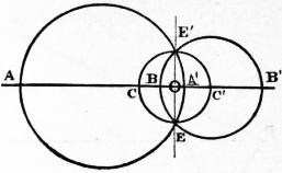
Fig. 32.
Every elliptical involution has the property that there are two definite points in the plane from which any two conjugate points are seen under a right angle.
At the same time the following problem has been solved:
To determine the centre and also the point corresponding to any given point in an elliptical involution of which two pairs of conjugate points are given.
§ 81. Involution Range on a Conic.—By the aid of § 53, the points on a conic may be made to correspond to those on a line, so that the row of points on the conic is projective to a row of points on a line. We may also have two projective rows on the same conic, and these will be in involution as soon as one point on the conic has the same point corresponding to it all the same to whatever row it belongs. An involution of points on a conic will have the property (as follows from its definition, and from § 53) that the lines which join conjugate points of the involution to any point on the conic are conjugate lines of an involution in a pencil, and that a fixed tangent is cut by the tangents at conjugate points on the conic in points which are again conjugate points of an involution on the fixed tangent. For such involution on a conic the following theorem holds:
The lines which join corresponding points in an involution on a conic all pass through a fixed point; and reciprocally, the points of intersection of conjugate lines in an involution among tangents to a conic lie on a line.
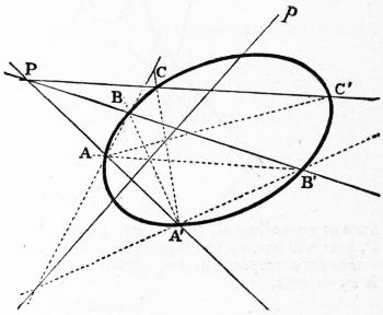
Fig. 33
We prove the first part only. The involution is determined by two pairs of conjugate points, say by A, A′ and B, B′ (fig. 33). Let AA′ and BB′ meet in P. If we join the points in involution to any point on the conic, and the conjugate points to another point on the conic, we obtain two projective pencils. We take A and A′ as centres of these pencils, so that the pencils A(A′BB′) and A′(AB′B) are projective, and in perspective position, because AA′ corresponds to A′A. Hence corresponding rays meet in a line, of which two points are found by joining AB′ to A′B and AB to A′B′. It follows that the axis of perspective is the polar of the point P, where AA′ and BB′ meet. If we now wish to construct to any other point C on the conic the corresponding point C′, we join C to A′ and the point where this line cuts p to A. The latter line cuts the conic again in C′. But we know from the theory of pole and polar that the line CC′ passes through P. The point of concurrence is called the “pole of the involution,” and the line of collinearity of the meets is called the “axis of the involution.”
Involution Determined by a Conic on a Line.—Foci
§ 82. The polars, with regard to a conic, of points in a row p form a pencil P projective to the row (§ 66). This pencil cuts the base of the row p in a projective row.
If A is a point in the given row, A′ the point where the polar of A cuts p, then A and A′ will be corresponding points. If we take A′ a point in the first row, then the polar of A′ will pass through A, so that A corresponds to A′—in other words, the rows are in involution. The conjugate points in this involution are conjugate points with regard to the conic. Conjugate points coincide only if the polar of a point A passes through A—that is, if A lies on the conic. Hence—
A conic determines on every line in its plane an involution, in which those points are conjugate which are also conjugate with regard to the conic.
If the line cuts the conic the involution is hyperbolic, the points of intersection being the foci.
If the line touches the conic the involution is parabolic, the two foci coinciding at the point of contact.
If the line does not cut the conic the involution is elliptic, having no foci.
If, on the other hand, we take a point P in the plane of a conic, we get to each line a through P one conjugate line which joins P to the pole of a. These pairs of conjugate lines through P form an involution in the pencil at P. The focal rays of this involution are the tangents drawn from P to the conic. This gives the theorem reciprocal to the last, viz:—
A conic determines in every pencil in its plane an involution, corresponding lines being conjugate lines with regard to the conic.
If the point is without the conic the involution is hyperbolic, the tangents from the points being the focal rays.
If the point lies on the conic the involution is parabolic, the tangent at the point counting for coincident focal rays.
If the point is within the conic the involution is elliptic, having no focal rays.
It will further be seen that the involution determined by a conic on any line p is a section of the involution, which is determined by the conic at the pole P of p.
§ 83. Foci.—The centre of a pencil in which the conic determines a circular involution is called a “focus” of the conic.
In other words, a focus is such a point that every line through it is perpendicular to its conjugate line. The polar to a focus is called a directrix of the conic.
From the definition it follows that every focus lies on an axis, for the line joining a focus to the centre of the conic is a diameter to which the conjugate lines are perpendicular; and every line joining two foci is an axis, for the perpendiculars to this line through the foci are conjugate to it. These conjugate lines pass through the pole of the line, the pole lies therefore at infinity, and the line is a diameter, hence by the last property an axis.
It follows that all foci lie on one axis, for no line joining a point in one axis to a point in the other can be an axis.
As the conic determines in the pencil which has its centre at a focus a circular involution, no tangents can be drawn from the focus to the conic. Hence each focus lies within a conic; and a directrix does not cut the conic.
Further properties are found by the following considerations:
§ 84. Through a point P one line p can be drawn, which is with regard to a given conic conjugate to a given line q, viz. that line which joins the point P to the pole of the line q. If the line q is made to describe a pencil about a point Q, then the line p will describe a pencil about P. These two pencils will be projective, for the line p passes through the pole of q, and whilst q describes the pencil Q, its pole describes a projective row, and this row is perspective to the pencil P.
We now take the point P on an axis of the conic, draw any line p through it, and from the pole of p draw a perpendicular q to p. Let q cut the axis in Q. Then, in the pencils of conjugate lines, which have their centres at P and Q, the lines p and q are conjugate lines at right angles to one another. Besides, to the axis as a ray in either pencil will correspond in the other the perpendicular to the axis (§ 72). The conic generated by the intersection of corresponding lines in the two pencils is therefore the circle on PQ as diameter, so that every line in P is perpendicular to its corresponding line in Q.
To every point P on an axis of a conic corresponds thus a point Q, such that conjugate lines through P and Q are perpendicular.
We shall show that these point-pairs P, Q form an involution. To do this let us move P along the axis, and with it the line p, keeping the latter parallel to itself. Then P describes a row, p a perspective pencil (of parallels), and the pole of p a projective row. At the same time the line q describes a pencil of parallels perpendicular to p, and perspective to the row formed by the pole of p. The point Q, therefore, where q cuts the axis, describes a row projective to the row of points P. The two points P and Q describe thus two projective rows on the axis; and not only does P as a point in the first row correspond to Q, but also Q as a point in the first corresponds to P. The two rows therefore form an involution. The centre of this involution, it is easily seen, is the centre of the conic.
A focus of this involution has the property that any two conjugate lines through it are perpendicular; hence, it is a focus to the conic.
Such involution exists on each axis. But only one of these can have foci, because all foci lie on the same axis. The involution on one of the axes is elliptic, and appears (§ 80) therefore as the section of two circular involutions in two pencils whose centres lie in the other axis. These centres are foci, hence the one axis contains two foci, the other axis none; or every central conic has two foci which lie on one axis equidistant from the centre.
The axis which contains the foci is called the principal axis; in case of an hyperbola it is the axis which cuts the curve, because the foci lie within the conic.
In case of the parabola there is but one axis. The involution on this axis has its centre at infinity. One focus is therefore at infinity, the one focus only is finite. A parabola has only one focus.
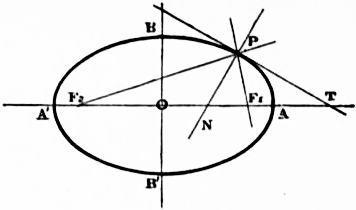
Fig. 34.
§ 85. If through any point P (fig. 34) on a conic the tangent PT and the normal PN (i.e. the perpendicular to the tangent through the point of contact) be drawn, these will be conjugate lines with regard to the conic, and at right angles to each other. They will therefore cut the principal axis in two points, which are conjugate in the involution considered in § 84; hence they are harmonic conjugates with regard to the foci. If therefore the two foci F1 and F2 be joined to P, these lines will be harmonic with regard to the tangent and normal. As the latter are perpendicular, they will bisect the angles between the other pair. Hence—
The lines joining any point on a conic to the two foci are equally inclined to the tangent and normal at that point.
In case of the parabola this becomes—
The line joining any point on a parabola to the focus and the diameter through the point, are equally inclined to the tangent and normal at that point.
From the definition of a focus it follows that—
The segment of a tangent between the directrix and the point of contact is seen from the focus belonging to the directrix under a right angle, because the lines joining the focus to the ends of this segment are conjugate with regard to the conic, and therefore perpendicular.
With equal ease the following theorem is proved:
The two lines which join the points of contact of two tangents each to one focus, but not both to the same, are seen from the intersection of the tangents under equal angles.
§ 86. Other focal properties of a conic are obtained by the following considerations:
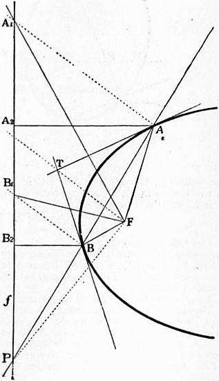
Fig. 35.
Let F (fig. 35) be a focus to a conic, f the corresponding directrix, A and B the points of contact of two tangents meeting at T, and P the point where the line AB cuts the directrix. Then TF will be the polar of P (because polars of F and T meet at P). Hence TF and PF are conjugate lines through a focus, and therefore perpendicular. They are further harmonic conjugates with regard to FA and FB (§§ 64 and 13), so that they bisect the angles formed by these lines. This by the way proves—
The segments between the point of intersection of two tangents to a conic and their points of contact are seen from a focus under equal angles.
If we next draw through A and B lines parallel to TF, then the points A1, B1 where these cut the directrix will be harmonic conjugates with regard to P and the point where FT cuts the directrix. The lines FT and FP bisect therefore also the angles between FA1 and FB1. From this it follows easily that the triangles FAA1 and FBB1 are equiangular, and therefore similar, so that FA : AA1 = FB : BB1.
The triangles AA1A2 and BB1B2 formed by drawing perpendiculars from A and B to the directrix are also similar, so that AA1 : AA2 = = BB1 : BB2. This, combined with the above proportion, gives FA : AA2 = FB : BB2. Hence the theorem:
The ratio of the distances of any point on a conic from a focus and the corresponding directrix is constant.
To determine this ratio we consider its value for a vertex on the principal axis. In an ellipse the focus lies between the two vertices on this axis, hence the focus is nearer to a vertex than to the corresponding directrix. Similarly, in an hyperbola a vertex is nearer to the directrix than to the focus. In a parabola the vertex lies halfway between directrix and focus.
It follows in an ellipse the ratio between the distance of a point from the focus to that from the directrix is less than unity, in the parabola it equals unity, and in the hyperbola it is greater than unity.
It is here the same which focus we take, because the two foci lie symmetrical to the axis of the conic. If now P is any point on the conic having the distances r1 and r2 from the foci and the distances d1 and d2 from the corresponding directrices, then r1/d1 = r2/d2 = e, where e is constant. Hence also (r1 ± r2) / (d1 ± d2) = e.
In the ellipse, which lies between the directrices, d1 + d2 is constant, therefore also r1 + r2. In the hyperbola on the other hand d1 − d2 is constant, equal to the distance between the directrices, therefore in this case r1 − r2 is constant.
If we call the distances of a point on a conic from the focus its focal distances we have the theorem:
In an ellipse the sum of the focal distances is constant; and in an hyperbola the difference of the focal distances is constant.
This constant sum or difference equals in both cases the length of the principal axis.
Pencil of Conics
§ 87. Through four points A, B, C, D in a plane, of which no three lie in a line, an infinite number of conics may be drawn, viz. through these four points and any fifth one single conic. This system of conics is called a pencil of conics. Similarly, all conics touching four fixed lines form a system such that any fifth tangent determines one and only one conic. We have here the theorems:
The pairs of points in which any line is cut by a system of conics through four fixed points are in involution. The pairs of tangents which can be drawn from a point to a system of conics touching four fixed lines are in involution.
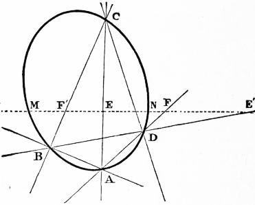
Fig. 36.
We prove the first theorem only. Let ABCD (fig. 36) be the four-point, then any line t will cut two opposite sides AC, BD in the points E, E′, the pair AD, BC in points F, F′, and any conic of the system in M, N, and we have A(CD, MN) = B(CD, MN).
If we cut these pencils by t we get
(EF, MN) = (F′E′, MN)
or
(EF, MN) = (E′F′, NM).
But this is, according to § 77 (7), the condition that M, N are corresponding points in the involution determined by the point pairs E, E′, F, F′ in which the line t cuts pairs of opposite sides of the four-point ABCD. This involution is independent of the particular conic chosen.
§ 88. There follow several important theorems:
Through four points two, one, or no conics may be drawn which touch any given line, according as the involution determined by the given four-point on the line has real, coincident or imaginary foci.
Two, one, or no conics may be drawn which touch four given lines and pass through a given point, according as the involution determined by the given four-side at the point has real, coincident or imaginary focal rays.
For the conic through four points which touches a given line has its point of contact at a focus of the involution determined by the four-point on the line.
As a special case we get, by taking the line at infinity:
Through four points of which none is at infinity either two or no parabolas may be drawn.
The problem of drawing a conic through four points and touching a given line is solved by determining the points of contact on the line, that is, by determining the foci of the involution in which the line cuts the sides of the four-point. The corresponding remark holds for the problem of drawing the conics which touch four lines and pass through a given point.
Ruled Quadric Surfaces
§ 89. We have considered hitherto projective rows which lie in the same plane, in which case lines joining corresponding points envelop a conic. We shall now consider projective rows whose bases do not meet. In this case, corresponding points will be joined by lines which do not lie in a plane, but on some surface, which like every surface generated by lines is called a ruled surface. This surface clearly contains the bases of the two rows.
If the points in either row be joined to the base of the other, we obtain two axial pencils which are also projective, those planes being corresponding which pass through corresponding points in the given rows. If A′, A be two corresponding points, α, α′ the planes in the axial pencils passing through them, then AA′ will be the line of intersection of the corresponding planes α, α′ and also the line joining corresponding points in the rows.
If we cut the whole figure by a plane this will cut the axial pencils in two projective flat pencils, and the curve of the second order generated by these will be the curve in which the plane cuts the surface. Hence
The locus of lines joining corresponding points in two projective rows which do not lie in the same plane is a surface which contains the bases of the rows, and which can also be generated by the lines of intersection of corresponding planes in two projective axial pencils. This surface is cut by every plane in a curve of the second order, hence either in a conic or in a line-pair. No line which does not lie altogether on the surface can have more than two points in common with the surface, which is therefore said to be of the second order or is called a ruled quadric surface.
That no line which does not lie on the surface can cut the surface in more than two points is seen at once if a plane be drawn through the line, for this will cut the surface in a conic. It follows also that a line which contains more than two points of the surface lies altogether on the surface.
§ 90. Through any point in space one line can always be drawn cutting two given lines which do not themselves meet.
If therefore three lines in space be given of which no two meet, then through every point in either one line may be drawn cutting the other two.
If a line moves so that it always cuts three given lines of which no two meet, then it generates a ruled quadric surface.
Let a, b, c be the given lines, and p, q, r ... lines cutting them in the points A, A′, A″ ...; B, B′, B″ ...; C, C′, C″ ... respectively; then the planes through a containing p, q, r, and the planes through b containing the same lines, may be taken as corresponding planes in two axial pencils which are projective, because both pencils cut the line c in the same row, C, C′, C″ ...; the surface can therefore be generated by projective axial pencils.
Of the lines p, q, r ... no two can meet, for otherwise the lines a, b, c which cut them would also lie in their plane. There is a single infinite number of them, for one passes through each point of a. These lines are said to form a set of lines on the surface.
If now three of the lines p, q, r be taken, then every line d cutting them will have three points in common with the surface, and will therefore lie altogether on it. This gives rise to a second set of lines on the surface. From what has been said the theorem follows:
A ruled quadric surface contains two sets of straight lines. Every line of one set cuts every line of the other, but no two lines of the same set meet.
Any two lines of the same set may be taken as bases of two projective rows, or of two projective pencils which generate the surface. They are cut by the lines of the other set in two projective rows.
The plane at infinity like every other plane cuts the surface either in a conic proper or in a line-pair. In the first case the surface is called an Hyperboloid of one sheet, in the second an Hyperbolic Paraboloid.
The latter may be generated by a line cutting three lines of which one lies at infinity, that is, cutting two lines and remaining parallel to a given plane.
Quadric Surfaces
§ 91. The conics, the cones of the second order, and the ruled quadric surfaces complete the figures which can be generated by projective rows or flat and axial pencils, that is, by those aggregates of elements which are of one dimension (§§ 5, 6). We shall now consider the simpler figures which are generated by aggregates of two dimensions. The space at our disposal will not, however, allow us to do more than indicate a few of the results.
§ 92. We establish a correspondence between the lines and planes in pencils in space, or reciprocally between the points and lines in two or more planes, but consider principally pencils.
In two pencils we may either make planes correspond to planes and lines to lines, or else planes to lines and lines to planes. If hereby the condition be satisfied that to a flat, or axial, pencil corresponds in the first case a projective flat, or axial, pencil, and in the second a projective axial, or flat, pencil, the pencils are said to be projective in the first case and reciprocal in the second.
For instance, two pencils which join two points S1 and S2 to the different points and lines in a given plane π are projective (and in perspective position), if those lines and planes be taken as corresponding which meet the plane π in the same point or in the same line. In this case every plane through both centres S1 and S2 of the two pencils will correspond to itself. If these pencils are brought into any other position they will be projective (but not perspective).
The correspondence between two projective pencils is uniquely determined, if to four rays (or planes) in the one the corresponding rays (or planes) in the other are given, provided that no three rays of either set lie in a plane.
Let a, b, c, d be four rays in the one, a′, b′, c′, d′ the corresponding rays in the other pencil. We shall show that we can find for every ray e in the first a single corresponding ray e′ in the second. To the axial pencil a (b, c, d ...) formed by the planes which join a to b, c, d ..., respectively corresponds the axial pencil a′ (b′, c′, d′ ... ), and this correspondence is determined. Hence, the plane a′e′ which corresponds to the plane ae is determined. Similarly the plane b′e′ may be found and both together determine the ray e′.
Similarly the correspondence between two reciprocal pencils is determined if for four rays in the one the corresponding planes in the other are given.
§ 93. We may now combine—
1. Two reciprocal pencils.
Each ray cuts its corresponding plane in a point, the locus of these points is a quadric surface.
2. Two projective pencils.
Each plane cuts its corresponding plane in a line, but a ray as a rule does not cut its corresponding ray. The locus of points where a ray cuts its corresponding ray is a twisted cubic. The lines where a plane cuts its corresponding plane are secants.
3. Three projective pencils.
The locus of intersection of corresponding planes is a cubic surface.
Of these we consider only the first two cases.
§ 94. If two pencils are reciprocal, then to a plane in either corresponds a line in the other, to a flat pencil an axial pencil, and so on. Every line cuts its corresponding plane in a point. If S1 and S2 be the centres of the two pencils, and P be a point where a line a1 in the first cuts its corresponding plane α2, then the line b2 in the pencil S2 which passes through P will meet its corresponding plane β1 in P. For b2 is a line in the plane α2. The corresponding plane β1 must therefore pass through the line a1, hence through P.
The points in which the lines in S1 cut the planes corresponding to them in S2 are therefore the same as the points in which the lines in S2 cut the planes corresponding to them in S1.
The locus of these points is a surface which is cut by a plane in a conic or in a line-pair and by a line in not more than two points unless it lies altogether on the surface. The surface itself is therefore called a quadric surface, or a surface of the second order.
To prove this we consider any line p in space.
The flat pencil in S1 which lies in the plane drawn through p and the corresponding axial pencil in S2 determine on p two projective rows, and those points in these which coincide with their corresponding points lie on the surface. But there exist only two, or one, or no such points, unless every point coincides with its corresponding point. In the latter case the line lies altogether on the surface.
This proves also that a plane cuts the surface in a curve of the second order, as no line can have more than two points in common with it. To show that this is a curve of the same kind as those considered before, we have to show that it can be generated by projective flat pencils. We prove first that this is true for any plane through the centre of one of the pencils, and afterwards that every point on the surface may be taken as the centre of such pencil. Let then α1 be a plane through S1. To the flat pencil in S1 which it contains corresponds in S2 a projective axial pencil with axis a2 and this cuts α1 in a second flat pencil. These two flat pencils in α1 are projective, and, in general, neither concentric nor perspective. They generate therefore a conic. But if the line a2 passes through S1 the pencils will have S1 as common centre, and may therefore have two, or one, or no lines united with their corresponding lines. The section of the surface by the plane α1 will be accordingly a line-pair or a single line, or else the plane α1 will have only the point S1 in common with the surface.
Every line l1 through S1 cuts the surface in two points, viz. first in S1 and then at the point where it cuts its corresponding plane. If now the corresponding plane passes through S1, as in the case just considered, then the two points where l1 cuts the surface coincide at S1, and the line is called a tangent to the surface with S1 as point of contact. Hence if l1 be a tangent, it lies in that plane τ1 which corresponds to the line S2S1 as a line in the pencil S2. The section of this plane has just been considered. It follows that—
All tangents to quadric surface at the centre of one of the reciprocal pencils lie in a plane which is called the tangent plane to the surface at that point as point of contact.
To the line joining the centres of the two pencils as a line in one corresponds in the other the tangent plane at its centre.
The tangent plane to a quadric surface either cuts the surface in two lines, or it has only a single line, or else only a single point in common with the surface.
In the first case the point of contact is said to be hyperbolic, in the second parabolic, in the third elliptic.
§ 95. It remains to be proved that every point S on the surface may be taken as centre of one of the pencils which generate the surface. Let S be any point on the surface Φ′ generated by the reciprocal pencils S1 and S2. We have to establish a reciprocal correspondence between the pencils S and S1, so that the surface generated by them is identical with Φ. To do this we draw two planes α1 and β1 through S1, cutting the surface Φ in two conics which we also denote by α1 and β1. These conics meet at S1, and at some other point T where the line of intersection of α1 and β1 cuts the surface.
In the pencil S we draw some plane σ which passes through T, but not through S1 or S2. It will cut the two conics first at T, and therefore each at some other point which we call A and B respectively. These we join to S by lines a and b, and now establish the required correspondence between the pencils S1 and S as follows:—To S1T shall correspond the plane σ, to the plane α1 the line a, and to β1 the line b, hence to the flat pencil in α1 the axial pencil a. These pencils are made projective by aid of the conic in α1.
In the same manner the flat pencil in β1 is made projective to the axial pencil b by aid of the conic in β1, corresponding elements being those which meet on the conic. This determines the correspondence, for we know for more than four rays in S1 the corresponding planes in S. The two pencils S and S1 thus made reciprocal generate a quadric surface Φ′, which passes through the point S and through the two conics α1 and β1.
The two surfaces Φ and Φ′ have therefore the points S and S1 and the conics α1 and β1 in common. To show that they are identical, we draw a plane through S and S2, cutting each of the conics α1 and β1 in two points, which will always be possible. This plane cuts Φ and Φ′ in two conics which have the point S and the points where it cuts α1 and β1 in common, that is five points in all. The conics therefore coincide.
This proves that all those points P on Φ′ lie on Φ which have the property that the plane SS2P cuts the conics α1, β1 in two points each. If the plane SS2P has not this property, then we draw a plane SS1P. This cuts each surface in a conic, and these conics have in common the points S, S1, one point on each of the conics α1, β1, and one point on one of the conics through S and S2 which lie on both surfaces, hence five points. They are therefore coincident, and our theorem is proved.
§ 96. The following propositions follow:—
A quadric surface has at every point a tangent plane.
Every plane section of a quadric surface is a conic or a line-pair.
Every line which has three points in common with a quadric surface lies on the surface.
Every conic which has five points in common with a quadric surface lies on the surface.
Through two conics which lie in different planes, but have two points in common, and through one external point always one quadric surface may be drawn.
§ 97. Every plane which cuts a quadric surface in a line-pair is a tangent plane. For every line in this plane through the centre of the line-pair (the point of intersection of the two lines) cuts the surface in two coincident points and is therefore a tangent to the surface, the centre of the line-pair being the point of contact.
If a quadric surface contains a line, then every plane through this line cuts the surface in a line-pair (or in two coincident lines). For this plane cannot cut the surface in a conic. Hence:—
If a quadric surface contains one line p then it contains an infinite number of lines, and through every point Q on the surface, one line q can be drawn which cuts p. For the plane through the point Q and the line p cuts the surface in a line-pair which must pass through Q and of which p is one line.
No two such lines q on the surface can meet. For as both meet p their plane would contain p and therefore cut the surface in a triangle.
Every line which cuts three lines q will be on the surface; for it has three points in common with it.
Hence the quadric surfaces which contain lines are the same as the ruled quadric surfaces considered in §§ 89-93, but with one important exception. In the last investigation we have left out of consideration the possibility of a plane having only one line (two coincident lines) in common with a quadric surface.
§ 98. To investigate this case we suppose first that there is one point A on the surface through which two different lines a, b can be drawn, which lie altogether on the surface.
If P is any other point on the surface which lies neither on a nor b, then the plane through P and a will cut the surface in a second line a′ which passes through P and which cuts a. Similarly there is a line b′ through P which cuts b. These two lines a′ and b′ may coincide, but then they must coincide with PA.
If this happens for one point P, it happens for every other point Q. For if two different lines could be drawn through Q, then by the same reasoning the line PQ would be altogether on the surface, hence two lines would be drawn through P against the assumption. From this follows:—
If there is one point on a quadric surface through which one, but only one, line can be drawn on the surface, then through every point one line can be drawn, and all these lines meet in a point. The surface is a cone of the second order.
If through one point on a quadric surface, two, and only two, lines can be drawn on the surface, then through every point two lines may be drawn, and the surface is ruled quadric surface.
If through one point on a quadric surface no line on the surface can be drawn, then the surface contains no lines.
Using the definitions at the end of § 95, we may also say:—
On a quadric surface the points are all hyperbolic, or all parabolic, or all elliptic.
As an example of a quadric surface with elliptical points, we mention the sphere which may be generated by two reciprocal pencils, where to each line in one corresponds the plane perpendicular to it in the other.
§ 99. Poles and Polar Planes.—The theory of poles and polars with regard to a conic is easily extended to quadric surfaces.
Let P be a point in space not on the surface, which we suppose not to be a cone. On every line through P which cuts the surface in two points we determine the harmonic conjugate Q of P with regard to the points of intersection. Through one of these lines we draw two planes α and β. The locus of the points Q in α is a line a, the polar of P with regard to the conic in which α cuts the surface. Similarly the locus of points Q in β is a line b. This cuts a, because the line of intersection of α and β contains but one point Q. The locus of all points Q therefore is a plane. This plane is called the polar plane of the point P, with regard to the quadric surface. If P lies on the surface we take the tangent plane of P as its polar.
The following propositions hold:—
1. Every point has a polar plane, which is constructed by drawing the polars of the point with regard to the conics in which two planes through the point cut the surface.
2. If Q is a point in the polar of P, then P is a point in the polar of Q, because this is true with regard to the conic in which a plane through PQ cuts the surface.
3. Every plane is the polar plane of one point, which is called the Pole of the plane.
The pole to a plane is found by constructing the polar planes of three points in the plane. Their intersection will be the pole.
4. The points in which the polar plane of P cuts the surface are points of contact of tangents drawn from P to the surface, as is easily seen. Hence:—
5. The tangents drawn from a point P to a quadric surface form a cone of the second order, for the polar plane of P cuts it in a conic.
6. If the pole describes a line a, its polar plane will turn about another line a′, as follows from 2. These lines a and a′ are said to be conjugate with regard to the surface.
§ 100. The pole of the line at infinity is called the centre of the surface. If it lies at the infinity, the plane at infinity is a tangent plane, and the surface is called a paraboloid.
The polar plane to any point at infinity passes through the centre, and is called a diametrical plane.
A line through the centre is called a diameter. It is bisected at the centre. The line conjugate to it lies at infinity.
If a point moves along a diameter its polar plane turns about the conjugate line at infinity; that is, it moves parallel to itself, its centre moving on the first line.
The middle points of parallel chords lie in a plane, viz. in the polar plane of the point at infinity through which the chords are drawn.
The centres of parallel sections lie in a diameter which is a line conjugate to the line at infinity in which the planes meet.
Twisted Cubics
§ 101. If two pencils with centres S1 and S2 are made projective, then to a ray in one corresponds a ray in the other, to a plane a plane, to a flat or axial pencil a projective flat or axial pencil, and so on.
There is a double infinite number of lines in a pencil. We shall see that a single infinite number of lines in one pencil meets its corresponding ray, and that the points of intersection form a curve in space.
Of the double infinite number of planes in the pencils each will meet its corresponding plane. This gives a system of a double infinite number of lines in space. We know (§ 5) that there is a quadruple infinite number of lines in space. From among these we may select those which satisfy one or more given conditions. The systems of lines thus obtained were first systematically investigated and classified by Plücker, in his Geometrie des Raumes. He uses the following names:—
A treble infinite number of lines, that is, all lines which satisfy one condition, are said to form a complex of lines; e.g. all lines cutting a given line, or all lines touching a surface.
A double infinite number of lines, that is, all lines which satisfy two conditions, or which are common to two complexes, are said to form a congruence of lines; e.g. all lines in a plane, or all lines cutting two curves, or all lines cutting a given curve twice.
A single infinite number of lines, that is, all lines which satisfy three conditions, or which belong to three complexes, form a ruled surface; e.g. one set of lines on a ruled quadric surface, or developable surfaces which are formed by the tangents to a curve.
It follows that all lines in which corresponding planes in two projective pencils meet form a congruence. We shall see this congruence consists of all lines which cut a twisted cubic twice, or of all secants to a twisted cubic.
§ 102. Let l1 be the line S1S2 as a line in the pencil S1. To it corresponds a line l2 in S2. At each of the centres two corresponding lines meet. The two axial pencils with l1 and l2 as axes are projective, and, as, their axes meet at S2, the intersections of corresponding planes form a cone of the second order (§ 58), with S2 as centre. If π1 and π2 be corresponding planes, then their intersection will be a line p2 which passes through S2. Corresponding to it in S1 will be a line p1 which lies in the plane π1, and which therefore meets p2 at some point P. Conversely, if p2 be any line in S2 which meets its corresponding line p1 at a point P, then to the plane l2p2 will correspond the plane l1p1, that is, the plane S1S2P. These planes intersect in p2, so that p2 is a line on the quadric cone generated by the axial pencils l1 and l2. Hence:—
All lines in one pencil which meet their corresponding lines in the other form a cone of the second order which has its centre at the centre of the first pencil, and passes through the centre of the second.
From this follows that the points in which corresponding rays meet lie on two cones of the second order which have the ray joining their centres in common, and form therefore, together with the line S1S2 or l1, the intersection of these cones. Any plane cuts each of the cones in a conic. These two conics have necessarily that point in common in which it cuts the line l1, and therefore besides either one or three other points. It follows that the curve is of the third order as a plane may cut it in three, but not in more than three, points. Hence:—
The locus of points in which corresponding lines on two projective pencils meet is a curve of the third order or a “twisted cubic” k, which passes through the centres of the pencils, and which appears as the intersection of two cones of the second order, which have one line in common.
A line belonging to the congruence determined by the pencils is a secant of the cubic; it has two, or one, or no points in common with this cubic, and is called accordingly a secant proper, a tangent, or a secant improper of the cubic. A secant improper may be considered, to use the language of coordinate geometry, as a secant with imaginary points of intersection.
§ 103. If a1 and a2 be any two corresponding lines in the two pencils, then corresponding planes in the axial pencils having a1 and a2 as axes generate a ruled quadric surface. If P be any point on the cubic k, and if p1, p2 be the corresponding rays in S1 and S2 which meet at P, then to the plane a1p1 in S1 corresponds a2p2 in S2. These therefore meet in a line through P.
This may be stated thus:—
Those secants of the cubic which cut a ray a1, drawn through the centre S1 of one pencil, form a ruled quadric surface which passes through both centres, and which contains the twisted cubic k. Of such surfaces an infinite number exists. Every ray through S1 or S2 which is not a secant determines one of them.
If, however, the rays a1 and a2 are secants meeting at A, then the ruled quadric surface becomes a cone of the second order, having A as centre. Or all lines of the congruence which pass through a point on the twisted cubic k form a cone of the second order. In other words, the projection of a twisted cubic from any point in the curve on to any plane is a conic.
If a1 is not a secant, but made to pass through any point Q in space, the ruled quadric surface determined by a1 will pass through Q. There will therefore be one line of the congruence passing through Q, and only one. For if two such lines pass through Q, then the lines S1Q and S2Q will be corresponding lines; hence Q will be a point on the cubic k, and an infinite number of secants will pass through it. Hence:—
Through every point in space not on the twisted cubic one and only one secant to the cubic can be drawn.
§ 104. The fact that all the secants through a point on the cubic form a quadric cone shows that the centres of the projective pencils generating the cubic are not distinguished from any other points on the cubic. If we take any two points S, S′ on the cubic, and draw the secants through each of them, we obtain two quadric cones, which have the line SS′ in common, and which intersect besides along the cubic. If we make these two pencils having S and S′ as centres projective by taking four rays on the one cone as corresponding to the four rays on the other which meet the first on the cubic, the correspondence is determined. These two pencils will generate a cubic, and the two cones of secants having S and S′ as centres will be identical with the above cones, for each has five rays in common with one of the first, viz. the line SS′ and the four lines determined for the correspondence; therefore these two cones intersect in the original cubic. This gives the theorem:—
On a twisted cubic any two points may be taken as centres of projective pencils which generate the cubic, corresponding planes being those which meet on the same secant.
Of the two projective pencils at S and S′ we may keep the first fixed, and move the centre of the other along the curve. The pencils will hereby remain projective, and a plane α in S will be cut by its corresponding plane α′ always in the same secant a. Whilst S′ moves along the curve the plane α′ will turn about a, describing an axial pencil.
Authorities.—In this article we have given a purely geometrical theory of conics, cones of the second order, quadric surfaces, &c. In doing so we have followed, to a great extent, Reye’s Geometrie der Lage, and to this excellent work those readers are referred who wish for a more exhaustive treatment of the subject. Other works especially valuable as showing the development of the subject are: Monge, Géométrie descriptive: Carnot, Géométrie de position (1803), containing a theory of transversals; Poncelet’s great work Traité des propriétés projectives des figures (1822); Möbins, Barycentrischer Calcul (1826); Steiner, Abhängigkeit geometrischer Gestalten (1832), containing the first full discussion of the projective relations between rows, pencils, &c.; Von Staudt, Geometrie der Lage (1847) and Beiträge zur Geometrie der Lage (1856-1860), in which a system of geometry is built up from the beginning without any reference to number, so that ultimately a number itself gets a geometrical definition, and in which imaginary elements are systematically introduced into pure geometry; Chasles, Aperçu historique (1837), in which the author gives a brilliant account of the progress of modern geometrical methods, pointing out the advantages of the different purely geometrical methods as compared with the analytical ones, but without taking as much account of the German as of the French authors; Id., Rapport sur les progrès de la géométrie (1870), a continuation of the Aperçu; Id., Traité de géométrie supérieure (1852); Cremona, Introduzione ad una teoria geometrica delle curve piane (1862) and its continuation Preliminari di una teoria geometrica delle superficie (German translations by Curtze). As more elementary books, we mention: Cremona, Elements of Projective Geometry, translated from the Italian by C. Leudesdorf (2nd ed., 1894); J.W. Russell, Pure Geometry (2nd ed., 1905).
(O. H.)
III. Descriptive Geometry
This branch of geometry is concerned with the methods for representing solids and other figures in three dimensions by drawings in one plane. The most important method is that which was invented by Monge towards the end of the 18th century. It is based on parallel projections to a plane by rays perpendicular to the plane. Such a projection is called orthographic (see Projection, § 18). If the plane is horizontal the projection is called the plan of the figure, and if the plane is vertical the elevation. In Monge’s method a figure is represented by its plan and elevation. It is therefore often called drawing in plan and elevation, and sometimes simply orthographic projection.
§ 1. We suppose then that we have two planes, one horizontal, the other vertical, and these we call the planes of plan and of elevation respectively, or the horizontal and the vertical plane, and denote them by the letters π1 and π2. Their line of intersection is called the axis, and will be denoted by xy.
If the surface of the drawing paper is taken as the plane of the plan, then the vertical plane will be the plane perpendicular to it through the axis xy. To bring this also into the plane of the drawing paper we turn it about the axis till it coincides with the horizontal plane. This process of turning one plane down till it coincides with another is called rabatting one to the other. Of course there is no necessity to have one of the two planes horizontal, but even when this is not the case it is convenient to retain the above names.
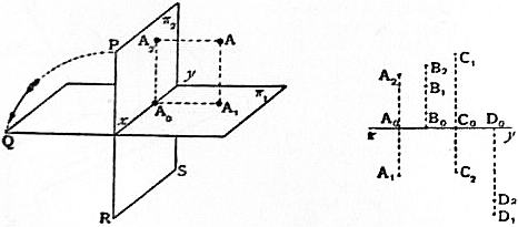
Fig. 37. Fig. 38.
The whole arrangement will be better understood by referring to fig. 37. A point A in space is there projected by the perpendicular AA1 and AA2 to the planes π1 and π2 so that A1 and A2 are the horizontal and vertical projections of A.
If we remember that a line is perpendicular to a plane that is perpendicular to every line in the plane if only it is perpendicular to any two intersecting lines in the plane, we see that the axis which is perpendicular both to AA1 and to AA2 is also perpendicular to A1A0 and to A2A0 because these four lines are all in the same plane. Hence, if the plane π2 be turned about the axis till it coincides with the plane π1, then A2A0 will be the continuation of A1A0. This position of the planes is represented in fig. 38, in which the line A1A2 is perpendicular to the axis x.
Conversely any two points A1, A2 in a line perpendicular to the axis will be the projections of some point in space when the plane π2 is turned about the axis till it is perpendicular to the plane π1, because in this position the two perpendiculars to the planes π1 and π2 through the points A1 and A2 will be in a plane and therefore meet at some point A.
Representation of Points.—We have thus the following method of representing in a single plane the position of points in space:—we take in the plane a line xy as the axis, and then any pair of points A1, A2 in the plane on a line perpendicular to the axis represent a point A in space. If the line A1A2 cuts the axis at A0, and if at A1 a perpendicular be erected to the plane, then the point A will be in it at a height A1A = A0A2 above the plane. This gives the position of the point A relative to the plane π1. In the same way, if in a perpendicular to π2 through A2 a point A be taken such that A2A = A0A1, then this will give the point A relative to the plane π2.
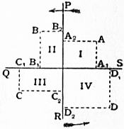
Fig. 39.
§ 2. The two planes π1, π2 in their original position divide space into four parts. These are called the four quadrants. We suppose that the plane π2 is turned as indicated in fig. 37, so that the point P comes to Q and R to S, then the quadrant in which the point A lies is called the first, and we say that in the first quadrant a point lies above the horizontal and in front of the vertical plane. Now we go round the axis in the sense in which the plane π2 is turned and come in succession to the second, third and fourth quadrant. In the second a point lies above the plane of the plan and behind the plane of elevation, and so on. In fig. 39, which represents a side view of the planes in fig. 37 the quadrants are marked, and in each a point with its projection is taken. Fig. 38 shows how these are represented when the plane π2 is turned down. We see that
A point lies in the first quadrant if the plan lies below, the elevation above the axis; in the second if plan and elevation both lie above; in the third if the plan lies above, the elevation below; in the fourth if plan and elevation both lie below the axis.
If a point lies in the horizontal plane, its elevation lies in the axis and the plan coincides with the point itself. If a point lies in the vertical plane, its plan lies in the axis and the elevation coincides with the point itself. If a point lies in the axis, both its plan and elevation lie in the axis and coincide with it.
Of each of these propositions, which will easily be seen to be true, the converse holds also.
§ 3. Representation of a Plane.—As we are thus enabled to represent points in a plane, we can represent any finite figure by representing its separate points. It is, however, not possible to represent a plane in this way, for the projections of its points completely cover the planes π1 and π2, and no plane would appear different from any other. But any plane α cuts each of the planes π1, π2 in a line. These are called the traces of the plane. They cut each other in the axis at the point where the latter cuts the plane α.
A plane is determined by its two traces, which are two lines that meet on the axis, and, conversely, any two lines which meet on the axis determine a plane.
If the plane is parallel to the axis its traces are parallel to the axis. Of these one may be at infinity; then the plane will cut one of the planes of projection at infinity and will be parallel to it. Thus a plane parallel to the horizontal plane of the plan has only one finite trace, viz. that with the plane of elevation.
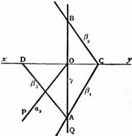
Fig. 40.
If the plane passes through the axis both its traces coincide with the axis. This is the only case in which the representation of the plane by its two traces fails. A third plane of projection is therefore introduced, which is best taken perpendicular to the other two. We call it simply the third plane and denote it by π3. As it is perpendicular to π1, it may be taken as the plane of elevation, its line of intersection γ with π1 being the axis, and be turned down to coincide with π1. This is represented in fig. 40. OC is the axis xy whilst OA and OB are the traces of the third plane. They lie in one line γ. The plane is rabatted about γ to the horizontal plane. A plane α through the axis xy will then show in it a trace α3. In fig. 40 the lines OC and OP will thus be the traces of a plane through the axis xy, which makes an angle POQ with the horizontal plane.
We can also find the trace which any other plane makes with π3. In rabatting the plane π3 its trace OB with the plane π2 will come to the position OD. Hence a plane β having the traces CA and CB will have with the third plane the trace β3, or AD if OD = OB.
It also follows immediately that—
If a plane α is perpendicular to the horizontal plane, then every point in it has its horizontal projection in the horizontal trace of the plane, as all the rays projecting these points lie in the plane itself.
Any plane which is perpendicular to the horizontal plane has its vertical trace perpendicular to the axis.
Any plane which is perpendicular to the vertical plane has its horizontal trace perpendicular to the axis and the vertical projections of all points in the plane lie in this trace.
§ 4. Representation of a Line.—A line is determined either by two points in it or by two planes through it. We get accordingly two representations of it either by projections or by traces.
First.—A line a is represented by its projections a1 and a2 on the two planes π1 and π2. These may be any two lines, for, bringing the planes π1, π2 into their original position, the planes through these lines perpendicular to π1 and π2 respectively will intersect in some line a which has a1, a2 as its projections.
Secondly.—A line a is represented by its traces—that is, by the points in which it cuts the two planes π1, π2. Any two points may be taken as the traces of a line in space, for it is determined when the planes are in their original position as the line joining the two traces. This representation becomes undetermined if the two traces coincide in the axis. In this case we again use a third plane, or else the projections of the line.
The fact that there are different methods of representing points and planes, and hence two methods of representing lines, suggests the principle of duality (section ii., Projective Geometry, § 41). It is worth while to keep this in mind. It is also worth remembering that traces of planes or lines always lie in the planes or lines which they represent. Projections do not as a rule do this excepting when the point or line projected lies in one of the planes of projection.
Having now shown how to represent points, planes and lines, we have to state the conditions which must hold in order that these elements may lie one in the other, or else that the figure formed by them may possess certain metrical properties. It will be found that the former are very much simpler than the latter.
Before we do this, however, we shall explain the notation used; for it is of great importance to have a systematic notation. We shall denote points in space by capitals A, B, C; planes in space by Greek letters α, β, γ; lines in space by small letters a, b, c; horizontal projections by suffixes 1, like A1, a1; vertical projections by suffixes 2, like A2, a2; traces by single and double dashes α′ α″, a′, a″. Hence P1 will be the horizontal projection of a point P in space; a line a will have the projections a1, a2 and the traces a′ and a″; a plane α has the traces α′ and α″.
§ 5. If a point lies in a line, the projections of the point lie in the projections of the line.
If a line lies in a plane, the traces of the line lie in the traces of the plane.
These propositions follow at once from the definitions of the projections and of the traces.
If a point lies in two lines its projections must lie in the projections of both. Hence
If two lines, given by their projections, intersect, the intersection of their planes and the intersection of their elevations must lie in a line perpendicular to the axis, because they must be the projections of the point common to the two lines.
Similarly—If two lines given by their traces lie in the same plane or intersect, then the lines joining their horizontal and vertical traces respectively must meet on the axis, because they must be the traces of the plane through them.
§ 6. To find the projections of a line which joins two points A, B given by their projections A1, A2 and B1, B2, we join A1, B1 and A2, B2; these will be the projections required. For example, the traces of a line are two points in the line whose projections are known or at all events easily found. They are the traces themselves and the feet of the perpendiculars from them to the axis.
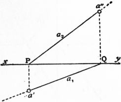
Fig. 41.
Hence if a′ a″ (fig. 41) are the traces of a line a, and if the perpendiculars from them cut the axis in P and Q respectively, then the line a′Q will be the horizontal and a″P the vertical projection of the line.
Conversely, if the projections a1, a2 of a line are given, and if these cut the axis in Q and P respectively, then the perpendiculars Pa′ and Qa″ to the axis drawn through these points cut the projections a1 and a2 in the traces a′ and a″.
To find the line of intersection of two planes, we observe that this line lies in both planes; its traces must therefore lie in the traces of both. Hence the points where the horizontal traces of the given planes meet will be the horizontal, and the point where the vertical traces meet the vertical trace of the line required.
§ 7. To decide whether a point A, given by its projections, lies in a plane α, given by its traces, we draw a line p by joining A to some point in the plane α and determine its traces. If these lie in the traces of the plane, then the line, and therefore the point A, lies in the plane; otherwise not. This is conveniently done by joining A1 to some point p′ in the trace α′; this gives p1; and the point where the perpendicular from p′ to the axis cuts the latter we join to A2; this gives p2. If the vertical trace of this line lies in the vertical trace of the plane, then, and then only, does the line p, and with it the point A, lie in the plane α.
§ 8. Parallel planes have parallel traces, because parallel planes are cut by any plane, hence also by π1 and by π2, in parallel lines.
Parallel lines have parallel projections, because points at infinity are projected to infinity.
If a line is parallel to a plane, then lines through the traces of the line and parallel to the traces of the plane must meet on the axis, because these lines are the traces of a plane parallel to the given plane.
§ 9. To draw a plane through two intersecting lines or through two parallel lines, we determine the traces of the lines; the lines joining their horizontal and vertical traces respectively will be the horizontal and vertical traces of the plane. They will meet, at a finite point or at infinity, on the axis if the lines do intersect.
To draw a plane through a line and a point without the line, we join the given point to any point in the line and determine the plane through this and the given line.
To draw a plane through three points which are not in a line, we draw two of the lines which each join two of the given points and draw the plane through them. If the traces of all three lines AB, BC, CA be found, these must lie in two lines which meet on the axis.
§ 10. We have in the last example got more points, or can easily get more points, than are necessary for the determination of the figure required—in this case the traces of the plane. This will happen in a great many constructions and is of considerable importance. It may happen that some of the points or lines obtained are not convenient in the actual construction. The horizontal traces of the lines AB and AC may, for instance, fall very near together, in which case the line joining them is not well defined. Or, one or both of them may fall beyond the drawing paper, so that they are practically non-existent for the construction. In this case the traces of the line BC may be used. Or, if the vertical traces of AB and AC are both in convenient position, so that the vertical trace of the required plane is found and one of the horizontal traces is got, then we may join the latter to the point where the vertical trace cuts the axis.
The draughtsman must remember that the lines which he draws are not mathematical lines without thickness, and therefore every drawing is affected by some errors. It is therefore very desirable to be able constantly to check the latter. Such checks always present themselves when the same result can be obtained by different constructions, or when, as in the above case, some lines must meet on the axis, or if three points must lie in a line. A careful draughtsman will always avail himself of these checks.
§ 11. To draw a plane through a given point parallel to a given plane α, we draw through the point two lines which are parallel to the plane α, and determine the plane through them; or, as we know that the traces of the required plane are parallel to those of the given one (§ 8), we need only draw one line l through the point parallel to the plane and find one of its traces, say the vertical trace l″; a line through this parallel to the vertical trace of α will be the vertical trace β″ of the required plane β, and a line parallel to the horizontal trace of α meeting β″ on the axis will be the horizontal trace β′.
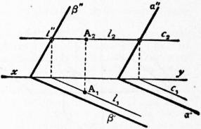
Fig. 42.
Let A1 A2 (fig. 42) be the given point, α′ α″ the given plane, a line l1 through A1, parallel to α′ and a horizontal line l2 through A2 will be the projections of a line l through A parallel to the plane, because the horizontal plane through this line will cut the plane α in a line c which has its horizontal projection c1 parallel to α′.
§ 12. We now come to the metrical properties of figures.
A line is perpendicular to a plane if the projections of the line are perpendicular to the traces of the plane. We prove it for the horizontal projection. If a line p is perpendicular to a plane α, every plane through p is perpendicular to α; hence also the vertical plane which projects the line p to p1. As this plane is perpendicular both to the horizontal plane and to the plane α, it is also perpendicular to their intersection—that is, to the horizontal trace of α. It follows that every line in this projecting plane, therefore also p1, the plan of p, is perpendicular to the horizontal trace of α.
To draw a plane through a given point A perpendicular to a given line p, we first draw through some point O in the axis lines γ′, γ″ perpendicular respectively to the projections p1 and p2 of the given line. These will be the traces of a plane γ which is perpendicular to the given line. We next draw through the given point A a plane parallel to the plane γ; this will be the plane required.
Other metrical properties depend on the determination of the real size or shape of a figure.
In general the projection of a figure differs both in size and shape from the figure itself. But figures in a plane parallel to a plane of projection will be identical with their projections, and will thus be given in their true dimensions. In other cases there is the problem, constantly recurring, either to find the true shape and size of a plane figure when plan and elevation are given, or, conversely, to find the latter from the known true shape of the figure itself. To do this, the plane is turned about one of its traces till it is laid down into that plane of projection to which the trace belongs. This is technically called rabatting the plane respectively into the plane of the plan or the elevation. As there is no difference in the treatment of the two cases, we shall consider only the case of rabatting a plane α into the plane of the plan. The plan of the figure is a parallel (orthographic) projection of the figure itself. The results of parallel projection (see Projection, §§ 17 and 18) may therefore now be used. The trace α′ will hereby take the place of what formerly was called the axis of projection. Hence we see that corresponding points in the plan and in the rabatted plane are joined by lines which are perpendicular to the trace α′ and that corresponding lines meet on this trace. We also see that the correspondence is completely determined if we know for one point or one line in the plan the corresponding point or line in the rabatted plane.
Before, however, we treat of this we consider some special cases.
§ 13. To determine the distance between two points A, B given by their projections A1, B1 and A2, B2, or, in other words, to determine the true length of a line the plan and elevation of which are given.
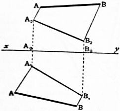
Fig. 43.
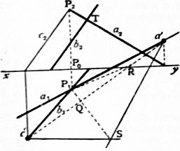
Fig. 44.
Solution.—The two points A, B in space lie vertically above their plans A1, B1 (fig. 43) and A1A = A0A2, B1B = B0B2. The four points A, B, A1, B1 therefore form a plane quadrilateral on the base A1B1 and having right angles at the base. This plane we rabatt about A1B1 by drawing A1A and B1B perpendicular to A1B1 and making A1A = A0A2, B1B = B0B2. Then AB will give the length required.
The construction might have been performed in the elevation by making A2A = A0A1 and B2B = B0B1 on lines perpendicular to A2B2. Of course AB must have the same length in both cases.
This figure may be turned into a model. Cut the paper along A1A, AB and BB1, and fold the piece A1ABB1 over along A1B1 till it stands upright at right angles to the horizontal plane. The points A, B will then be in their true position in space relative to π1. Similarly if B2BAA2 be cut out and turned along A2B2 through a right angle we shall get AB in its true position relative to the plane π2. Lastly we fold the whole plane of the paper along the axis x till the plane π2 is at right angles to π1. In this position the two sets of points AB will coincide if the drawing has been accurate.
Models of this kind can be made in many cases and their construction cannot be too highly recommended in order to realize orthographic projection.
§ 14. To find the angle between two given lines a, b of which the projections a1, b1 and a2, b2 are given.
Solution.—Let a1, b1 (fig. 44) meet in P1, a2, b2 in T, then if the line P1T is not perpendicular to the axis the two lines will not meet. In this case we draw a line parallel to b to meet the line a. This is easiest done by drawing first the line P1P2 perpendicular to the axis to meet a2 in P2, and then drawing through P2 a line c2 parallel to b2; then b1, c2 will be the projections of a line c which is parallel to b and meets a in P. The plane α which these two lines determine we rabatt to the plan. We determine the traces a′ and c′ of the lines a and c; then a′c′ is the trace α′ of their plane. On rabatting the point P comes to a point S on the line P1Q perpendicular to a′c′, so that QS = QP. But QP is the hypotenuse of a triangle PP1Q with a right angle P1. This we construct by making QR = P0P2; then P1R = PQ. The lines a′S and c′S will therefore include angles equal to those made by the given lines. It is to be remembered that two lines include two angles which are supplementary. Which of these is to be taken in any special case depends upon the circumstances.
To determine the angle between a line and a plane, we draw through any point in the line a perpendicular to the plane (§ 12) and determine the angle between it and the given line. The complement of this angle is the required one.
To determine the angle between two planes, we draw through any point two lines perpendicular to the two planes and determine the angle between the latter as above.
In special cases it is simpler to determine at once the angle between the two planes by taking a plane section perpendicular to the intersection of the two planes and rabatt this. This is especially the case if one of the planes is the horizontal or vertical plane of projection.
Thus in fig. 45 the angle P1QR is the angle which the plane α makes with the horizontal plane.
§ 15. We return to the general case of rabatting a plane α of which the traces α′ α″ are given.
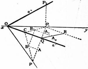
Fig. 45.
Here it will be convenient to determine first the position which the trace α″—which is a line in α—assumes when rabatted. Points in this line coincide with their elevations. Hence it is given in its true dimension, and we can measure off along it the true distance between two points in it. If therefore (fig. 45) P is any point in α″ originally coincident with its elevation P2, and if O is the point where α″ cuts the axis xy, so that O is also in α′, then the point P will after rabatting the plane assume such a position that OP = OP2. At the same time the plan is an orthographic projection of the plane α. Hence the line joining P to the plan P1 will after rabatting be perpendicular to α′. But P1 is known; it is the foot of the perpendicular from P2 to the axis xy. We draw therefore, to find P, from P1 a perpendicular P1Q to α′ and find on it a point P such that OP = OP2. Then the line OP will be the position of α″ when rabatted. This line corresponds therefore to the plan of α″—that is, to the axis xy, corresponding points on these lines being those which lie on a perpendicular to α′.
We have thus one pair of corresponding lines and can now find for any point B1 in the plan the corresponding point B in the rabatted plane. We draw a line through B1, say B1P1, cutting α′ in C. To it corresponds the line CP, and the point where this is cut by the projecting ray through B1, perpendicular to α′, is the required point B.
Similarly any figure in the rabatted plane can be found when the plan is known; but this is usually found in a different manner without any reference to the general theory of parallel projection. As this method and the reasoning employed for it have their peculiar advantages, we give it also.
Supposing the planes π1 and π2 to be in their positions in space perpendicular to each other, we take a section of the whole figure by a plane perpendicular to the trace α′ about which we are going to rabatt the plane α. Let this section pass through the point Q in α′. Its traces will then be the lines QP1 and P1P2 (fig. 9). These will be at right angles, and will therefore, together with the section QP2 of the plane α, form a right-angled triangle QP1P2 with the right angle at P1, and having the sides P1Q and P1P2 which both are given in their true lengths. This triangle we rabatt about its base P1Q, making P1R = P1P2. The line QR will then give the true length of the line QP in space. If now the plane α be turned about α′ the point P will describe a circle about Q as centre with radius QP = QR, in a plane perpendicular to the trace α′. Hence when the plane α has been rabatted into the horizontal plane the point P will lie in the perpendicular P1Q to α′, so that QP = QR.
If A1 is the plan of a point A in the plane α, and if A1 lies in QP1, then the point A will lie vertically above A1 in the line QP. On turning down the triangle QP1P2, the point A will come to A0, the line A1A0 being perpendicular to QP1. Hence A will be a point in QP such that QA = QA0.
If B1 is the plan of another point, but such that A1B1 is parallel to α′, then the corresponding line AB will also be parallel to α′. Hence, if through A a line AB be drawn parallel to α′, and B1B perpendicular to α′, then their intersection gives the point B. Thus of any point given in plan the real position in the plane α, when rabatted, can be found by this second method. This is the one most generally given in books on geometrical drawing. The first method explained is, however, in most cases preferable as it gives the draughtsman a greater variety of constructions. It requires a somewhat greater amount of theoretical knowledge.
If instead of our knowing the plan of a figure the latter is itself given, then the process of finding the plan is the reverse of the above and needs little explanation. We give an example.
§ 16. It is required to draw the plan and elevation of a polygon of which the real shape and position in a given plane α are known.
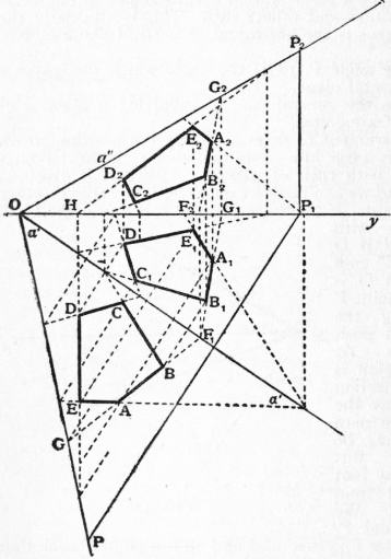
Fig. 46.
We first rabatt the plane α (fig. 46) as before so that P1 comes to P, hence OP1 to OP. Let the given polygon in α be the figure ABCDE. We project, not the vertices, but the sides. To project the line AB, we produce it to cut α′ in F and OP in G, and draw GG1 perpendicular to α′; then G1 corresponds to G, therefore FG1 to FG. In the same manner we might project all the other sides, at least those which cut OF and OP in convenient points. It will be best, however, first to produce all the sides to cut OP and α′ and then to draw all the projecting rays through A, B, C ... perpendicular to α′, and in the same direction the lines G, G1, &c. By drawing FG we get the points A1, B1 on the projecting ray through A and B. We then join B to the point M where BC produced meets the trace α′. This gives C1. So we go on till we have found E1. The line A1 E1 must then meet AE in α′, and this gives a check. If one of the sides cuts α′ or OP beyond the drawing paper this method fails, but then we may easily find the projection of some other line, say of a diagonal, or directly the projection of a point, by the former methods. The diagonals may also serve to check the drawing, for two corresponding diagonals must meet in the trace α′.
Having got the plan we easily find the elevation. The elevation of G is above G1 in α″, and that of F is at F2 in the axis. This gives the elevation F2G2 of FG and in it we get A2B2 in the verticals through A1 and B1. As a check we have OG = OG2. Similarly the elevation of the other sides and vertices are found.
§ 17. We proceed to give some applications of the above principles to the representation of solids and of the solution of problems connected with them.
Of a pyramid are given its base, the length of the perpendicular from the vertex to the base, and the point where this perpendicular cuts the base; it is required first to develop the whole surface of the pyramid into one plane, and second to determine its section by a plane which cuts the plane of the base in a given line and makes a given angle with it.
1. As the planes of projection are not given we can take them as we like, and we select them in such a manner that the solution becomes as simple as possible. We take the plane of the base as the horizontal plane and the vertical plane perpendicular to the plane of the section. Let then (fig. 47) ABCD be the base of the pyramid, V1 the plan of the vertex, then the elevations of A, B, C, D will be in the axis at A2, B2, C2, D2, and the vertex at some point V2 above V1 at a known distance from the axis. The lines V1A, V1B, &c., will be the plans and the lines V2A2, V2B2, &c., the elevations of the edges of the pyramid, of which thus plan and elevation are known.
We develop the surface into the plane of the base by turning each lateral face about its lower edge into the horizontal plane by the method used in § 14. If one face has been turned down, say ABV to ABP, then the point Q to which the vertex of the next face BCV comes can be got more simply by finding on the line V1Q perpendicular to BC the point Q such that BQ = BP, for these lines represent the same edge BV of the pyramid. Next R is found by making CR = CQ, and so on till we have got the last vertex—in this case S. The fact that AS must equal AP gives a convenient check.
2. The plane α whose section we have to determine has its horizontal trace given perpendicular to the axis, and its vertical trace makes the given angle with the axis. This determines it. To find the section of the pyramid by this plane there are two methods applicable: we find the sections of the plane either with the faces or with the edges of the pyramid. We use the latter.
As the plane α is perpendicular to the vertical plane, the trace α″ contains the projection of every figure in it; the points E2, F2, G2, H2 where this trace cuts the elevations of the edges will therefore be the elevations of the points where the edges cut α. From these we find the plans E1, F1, G1, H1, and by joining them the plan of the section. If from E1, F1 lines be drawn perpendicular to AB, these will determine the points E, F on the developed face in which the plane α cuts it; hence also the line EF. Similarly on the other faces. Of course BF must be the same length on BP and on BQ. If the plane α be rabatted to the plan, we get the real shape of the section as shown in the figure in EFGH. This is done easily by making F0F = OF2, &c. If the figure representing the development of the pyramid, or better a copy of it, is cut out, and if the lateral faces be bent along the lines AB, BC, &c., we get a model of the pyramid with the section marked on its faces. This may be placed on its plan ABCD and the plane of elevation bent about the axis x. The pyramid stands then in front of its elevations. If next the plane α with a hole cut out representing the true section be bent along the trace α′ till its edge coincides with α″, the edges of the hole ought to coincide with the lines EF, FG, &c., on the faces.
§ 18. Polyhedra like the pyramid in § 17 are represented by the projections of their edges and vertices. But solids bounded by curved surfaces, or surfaces themselves, cannot be thus represented.
For a surface we may use, as in case of the plane, its traces—that is, the curves in which it cuts the planes of projection. We may also project points and curves on the surface. A ray cuts the surface generally in more than one point; hence it will happen that some of the rays touch the surface, if two of these points coincide. The points of contact of these rays will form some curve on the surface, and this will appear from the centre of projection as the boundary of the surface or of part of the surface. The outlines of all surfaces of solids which we see about us are formed by the points at which rays through our eye touch the surface. The projections of these contours are therefore best adapted to give an idea of the shape of a surface.
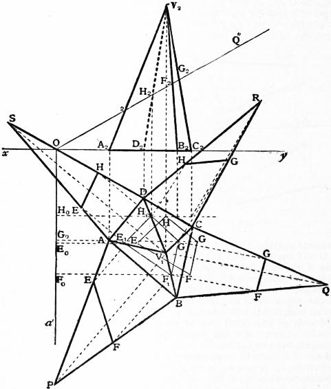
Fig. 47.
Thus the tangents drawn from any finite centre to a sphere form a right circular cone, and this will be cut by any plane in a conic. It is often called the projection of a sphere, but it is better called the contour-line of the sphere, as it is the boundary of the projections of all points on the sphere.
If the centre is at infinity the tangent cone becomes a right circular cylinder touching the sphere along a great circle, and if the projection is, as in our case, orthographic, then the section of this cone by a plane of projection will be a circle equal to the great circle of the sphere. We get such a circle in the plan and another in the elevation, their centres being plan and elevation of the centre of the sphere.
Similarly the rays touching a cone of the second order will lie in two planes which pass through the vertex of the cone, the contour-line of the projection of the cone consists therefore of two lines meeting in the projection of the vertex. These may, however, be invisible if no real tangent rays can be drawn from the centre of projection; and this happens when the ray projecting the centre of the vertex lies within the cone. In this case the traces of the cone are of importance. Thus in representing a cone of revolution with a vertical axis we get in the plan a circular trace of the surface whose centre is the plan of the vertex of the cone, and in the elevation the contour, consisting of a pair of lines intersecting in the elevation of the vertex of the cone. The circle in the plan and the pair of lines in the elevation do not determine the surface, for an infinite number of surfaces might be conceived which pass through the circular trace and touch two planes through the contour lines in the vertical plane. The surface becomes only completely defined if we write down to the figure that it shall represent a cone. The same holds for all surfaces. Even a plane is fully represented by its traces only under the silent understanding that the traces are those of a plane.
§ 19. Some of the simpler problems connected with the representation of surfaces are the determination of plane sections and of the curves of intersection of two such surfaces. The former is constantly used in nearly all problems concerning surfaces. Its solution depends of course on the nature of the surface.
To determine the curve of intersection of two surfaces, we take a plane and determine its section with each of the two surfaces, rabatting this plane if necessary. This gives two curves which lie in the same plane and whose intersections will give us points on both surfaces. It must here be remembered that two curves in space do not necessarily intersect, hence that the points in which their projections intersect are not necessarily the projections of points common to the two curves. This will, however, be the case if the two curves lie in a common plane. By taking then a number of plane sections of the surfaces we can get as many points on their curve of intersection as we like. These planes have, of course, to be selected in such a way that the sections are curves as simple as the case permits of, and such that they can be easily and accurately drawn. Thus when possible the sections should be straight lines or circles. This not only saves time in drawing but determines all points on the sections, and therefore also the points where the two curves meet, with equal accuracy.
§ 20. We give a few examples how these sections have to be selected. A cone is cut by every plane through the vertex in lines, and if it is a cone of revolution by planes perpendicular to the axis in circles.
A cylinder is cut by every plane parallel to the axis in lines, and if it is a cylinder of revolution by planes perpendicular to the axis in circles.
A sphere is cut by every plane in a circle.
Hence in case of two cones situated anywhere in space we take sections through both vertices. These will cut both cones in lines. Similarly in case of two cylinders we may take sections parallel to the axis of both. In case of a sphere and a cone of revolution with vertical axis, horizontal sections will cut both surfaces in circles whose plans are circles and whose elevations are lines, whilst vertical sections through the vertex of the cone cut the latter in lines and the sphere in circles. To avoid drawing the projections of these circles, which would in general be ellipses, we rabatt the plane and then draw the circles in their real shape. And so on in other cases.
Special attention should in all cases be paid to those points in which the tangents to the projection of the curve of intersection are parallel or perpendicular to the axis x, or where these projections touch the contour of one of the surfaces.
(O. H.)
IV. Analytical Geometry
1. In the name geometry there is a lasting record that the science had its origin in the knowledge that two distances may be compared by measurement, and in the idea that measurement must be effectual in the dissociation of different directions as well as in the comparison of distances in the same direction. The distance from an observer’s eye of an object seen would be specified as soon as it was ascertained that a rod, straight to the eye and of length taken as known, could be given the direction of the line of vision, and had to be moved along it a certain number of times through lengths equal to its own in order to reach the object from the eye. Moreover, if a field had for two of its boundaries lines straight to the eye, one running from south to north and the other from west to east, the position of a point in the field would be specified if the rod, when directed west, had to be shifted from the point one observed number of times westward to meet the former boundary, and also, when directed south, had to be shifted another observed number of times southward to meet the latter. Comparison by measurement, the beginning of geometry, involved counting, the basis of arithmetic; and the science of number was marked out from the first as of geometrical importance.
But the arithmetic of the ancients was inadequate as a science of number. Though a length might be recognized as known when measurement certified that it was so many times a standard length, it was not every length which could be thus specified in terms of the same standard length, even by an arithmetic enriched with the notion of fractional number. The idea of possible incommensurability of lengths was introduced into Europe by Pythagoras; and the corresponding idea of irrationality of number was absent from a crude arithmetic, while there were great practical difficulties in the way of its introduction. Hence perhaps it arose that, till comparatively modern times, appeal to arithmetical aid in geometrical reasoning was in all possible ways restrained. Geometry figured rather as the helper of the more difficult science of arithmetic.
2. It was reserved for algebra to remove the disabilities of arithmetic, and to restore the earliest ideas of the land-measurer to the position of controlling ideas in geometrical investigation. This unified science of pure number made comparatively little headway in the hands of the ancients, but began to receive due attention shortly after the revival of learning. It expresses whole classes of arithmetical facts in single statements, gives to arithmetical laws the form of equations involving symbols which may mean any known or sought numbers, and provides processes which enable us to analyse the information given by an equation and derive from that equation other equations, which express laws that are in effect consequences or causes of a law started from, but differ greatly from it in form. Above all, for present purposes, it deals not only with integral and fractional number, but with number regarded as capable of continuous growth, just as distance is capable of continuous growth. The difficulty of the arithmetical expression of irrational number, a difficulty considered by the modern school of analysts to have been at length surmounted (see Function), is not vital to it. It can call the ratio of the diagonal of a square to a side, for instance, or that of the circumference of a circle to a diameter, a number, and let a or x denote that number, just as properly as it may allow either letter to denote any rational number which may be greater or less than the ratio in question by a difference less than any minute one we choose to assign.