VOLUME IX SLICE II Ehud to Electroscope (continued 9)
Reading edition
The affinities of acids have been compared in several ways. W. Ostwald (Lehrbuch der allg. Chemie, vol. ii., Leipzig, 1893) investigated the relative affinities of acids for potash, soda and ammonia, and proved them to be independent of the base used. The method employed was to measure the changes in volume caused by the action. His results are given in column I. of the following table, the affinity of hydrochloric acid being taken as one hundred. Another method is to allow an acid to act on an insoluble salt, and to measure the quantity which goes into solution. Determinations have been made with calcium oxalate, CaC2O4 + H2O, which is easily decomposed by acids, oxalic acid and a soluble calcium salt being formed. The affinities of acids relative to that of oxalic acid are thus found, so that the acids can be compared among themselves (column II.). If an aqueous solution of methyl acetate be allowed to stand, a slow decomposition goes on. This is much quickened by the presence of a little dilute acid, though the acid itself remains unchanged. It is found that the influence of different acids on this action is proportional to their specific coefficients of affinity. The results of this method are given in column III. Finally, in column IV. the electrical conductivities of normal solutions of the acids have been tabulated. A better basis of comparison would be the ratio of the actual to the limiting conductivity, but since the conductivity of acids is chiefly due to the mobility of the hydrogen ions, its limiting value is nearly the same for all, and the general result of the comparison would be unchanged.
Acid. I. II. III. IV.
Hydrochloric 100 100 100 100
Nitric 102 110 92 99.6
Sulphuric 68 67 74 65.1
Formic 4.0 2.5 1.3 1.7
Acetic 1.2 1.0 0.3 0.4
Propionic 1.1 · · 0.3 0.3
Monochloracetic 7.2 5.1 4.3 4.9
Dichloracetic 34 18 23.0 25.3
Trichloracetic 82 63 68.2 62.3
Malic 3.0 5.0 1.2 1.3
Tartaric 5.3 6.3 2.3 2.3
Succinic 0.1 0.2 0.5 0.6
It must be remembered that, the solutions not being of quite the same strength, these numbers are not strictly comparable, and that the experimental difficulties involved in the chemical measurements are considerable. Nevertheless, the remarkable general agreement of the numbers in the four columns is quite enough to show the intimate connexion between chemical activity and electrical conductivity. We may take it, then, that only that portion of these bodies is chemically active which is electrolytically active—that ionization is necessary for such chemical activity as we are dealing with here, just as it is necessary for electrolytic conductivity.
The ordinary laws of chemical equilibrium have been applied to the case of the dissociation of a substance into its ions. Let x be the number of molecules which dissociate per second when the number of undissociated molecules in unit volume is unity, then in a dilute solution where the molecules do not interfere with each other, xp is the number when the concentration is p. Recombination can only occur when two ions meet, and since the frequency with which this will happen is, in dilute solution, proportional to the square of the ionic concentration, we shall get for the number of molecules re-formed in one second yq² where q is the number of dissociated molecules in one cubic centimetre. When there is equilibrium, xp = yq². If μ be the molecular conductivity, and μ ∞ its value at infinite dilution, the fractional number of molecules dissociated is μ / μ ∞, which we may write as α. The number of undissociated molecules is then 1 − α, so that if V be the volume of the solution containing 1 gramme-molecule of the dissolved substance, we get
q = α / V and p = (1 − α) / V,
hence
x (1 − α) V = ya² / V²,
and
α² = x = constant = k.
V (1 − α) y
This constant k gives a numerical value for the chemical affinity, and the equation should represent the effect of dilution on the molecular conductivity of binary electrolytes.
In the case of substances like ammonia and acetic acid, where the dissociation is very small, 1 − α is nearly equal to unity, and only varies slowly with dilution. The equation then becomes α²/V = k, or α = √(Vk), so that the molecular conductivity is proportional to the square root of the dilution. Ostwald has confirmed the equation by observation on an enormous number of weak acids (Zeits. physikal. Chemie, 1888, ii. p. 278; 1889, iii. pp. 170, 241, 369). Thus in the case of cyanacetic acid, while the volume V changed by doubling from 16 to 1024 litres, the values of k were 0.00 (376, 373, 374, 361, 362, 361, 368). The mean values of k for other common acids were—formic, 0.0000214; acetic, 0.0000180; monochloracetic, 0.00155; dichloracetic, 0.051; trichloracetic, 1.21; propionic, 0.0000134. From these numbers we can, by help of the equation, calculate the conductivity of the acids for any dilution. The value of k, however, does not keep constant so satisfactorily in the case of highly dissociated substances, and empirical formulae have been constructed to represent the effect of dilution on them. Thus the values of the expressions α² / (1 − α√V) (Rudolphi, Zeits. physikal. Chemie, 1895, vol. xvii. p. 385) and α³ / (1 − α)²V (van ’t Hoff, ibid., 1895, vol. xviii. p. 300) are found to keep constant as V changes. Van ’t Hoff’s formula is equivalent to taking the frequency of dissociation as proportional to the square of the concentration of the molecules, and the frequency of recombination as proportional to the cube of the concentration of the ions. An explanation of the failure of the usual dilution law in these cases may be given if we remember that, while the electric forces between bodies like undissociated molecules, each associated with equal and opposite charges, will vary inversely as the fourth power of the distance, the forces between dissociated ions, each carrying one charge only, will be inversely proportional to the square of the distance. The forces between the ions of a strongly dissociated solution will thus be considerable at a dilution which makes forces between undissociated molecules quite insensible, and at the concentrations necessary to test Ostwald’s formula an electrolyte will be far from dilute in the thermodynamic sense of the term, which implies no appreciable intermolecular or interionic forces.
When the solutions of two substances are mixed, similar considerations to those given above enable us to calculate the resultant changes in dissociation. (See Arrhenius, loc. cit.) The simplest and most important case is that of two electrolytes having one ion in common, such as two acids. It is evident that the undissociated part of each acid must eventually be in equilibrium with the free hydrogen ions, and, if the concentrations are not such as to secure this condition, readjustment must occur. In order that there should be no change in the states of dissociation on mixing, it is necessary, therefore, that the concentration of the hydrogen ions should be the same in each separate solution. Such solutions were called by Arrhenius “isohydric.” The two solutions, then, will so act on each other when mixed that they become isohydric. Let us suppose that we have one very active acid like hydrochloric, in which dissociation is nearly complete, another like acetic, in which it is very small. In order that the solutions of these should be isohydric and the concentrations of the hydrogen ions the same, we must have a very large quantity of the feebly dissociated acetic acid, and a very small quantity of the strongly dissociated hydrochloric, and in such proportions alone will equilibrium be possible. This explains the action of a strong acid on the salt of a weak acid. Let us allow dilute sodium acetate to react with dilute hydrochloric acid. Some acetic acid is formed, and this process will go on till the solutions of the two acids are isohydric: that is, till the dissociated hydrogen ions are in equilibrium with both. In order that this should hold, we have seen that a considerable quantity of acetic acid must be present, so that a corresponding amount of the salt will be decomposed, the quantity being greater the less the acid is dissociated. This “replacement” of a “weak” acid by a “strong” one is a matter of common observation in the chemical laboratory. Similar investigations applied to the general case of chemical equilibrium lead to an expression of exactly the same form as that given by C.M. Guldberg and P. Waage, which is universally accepted as an accurate representation of the facts.
The temperature coefficient of conductivity has approximately the same value for most aqueous salt solutions. It decreases both as the temperature is raised and as the concentration is increased, ranging from about 3.5% per degree for extremely dilute solutions (i.e. practically pure water) at 0° to about 1.5 for concentrated solutions at 18°. For acids its value is usually rather less than for salts at equivalent concentrations. The influence of temperature on the conductivity of solutions depends on (1) the ionization, and (2) the frictional resistance of the liquid to the passage of the ions, the reciprocal of which is called the ionic fluidity. At extreme dilution, when the ionization is complete, a variation in temperature cannot change its amount. The rise of conductivity with temperature, therefore, shows that the fluidity becomes greater when the solution is heated. As the concentration is increased and un-ionized molecules are formed, a change in temperature begins to affect the ionization as well as the fluidity. But the temperature coefficient of conductivity is now generally less than before; thus the effect of temperature on ionization must be of opposite sign to its effect on fluidity. The ionization of a solution, then, is usually diminished by raising the temperature, the rise in conductivity being due to the greater increase in fluidity. Nevertheless, in certain cases, the temperature coefficient of conductivity becomes negative at high temperatures, a solution of phosphoric acid, for example, reaching a maximum conductivity at 75° C.
The dissociation theory gives an immediate explanation of the fact that, in general, no heat-change occurs when two neutral salt solutions are mixed. Since the salts, both before and after mixture, exist mainly as dissociated ions, it is obvious that large thermal effects can only appear when the state of dissociation of the products is very different from that of the reagents. Let us consider the case of the neutralization of a base by an acid in the light of the dissociation theory. In dilute solution such substances as hydrochloric acid and potash are almost completely dissociated, so that, instead of representing the reaction as
HCl + KOH = KCl + H2O,
we must write
+ − + − + − H + Cl + K + OH = K + Cl + H2O.
The ions K and Cl suffer no change, but the hydrogen of the acid and the hydroxyl (OH) of the potash unite to form water, which is only very slightly dissociated. The heat liberated, then, is almost exclusively that produced by the formation of water from its ions. An exactly similar process occurs when any strongly dissociated acid acts on any strongly dissociated base, so that in all such cases the heat evolution should be approximately the same. This is fully borne out by the experiments of Julius Thomsen, who found that the heat of neutralization of one gramme-molecule of a strong base by an equivalent quantity of a strong acid was nearly constant, and equal to 13,700 or 13,800 calories. In the case of weaker acids, the dissociation of which is less complete, divergences from this constant value will occur, for some of the molecules have to be separated into their ions. For instance, sulphuric acid, which in the fairly strong solutions used by Thomsen is only about half dissociated, gives a higher value for the heat of neutralization, so that heat must be evolved when it is ionized. The heat of formation of a substance from its ions is, of course, very different from that evolved when it is formed from its elements in the usual way, since the energy associated with an ion is different from that possessed by the atoms of the element in their normal state. We can calculate the heat of formation from its ions for any substance dissolved in a given liquid, from a knowledge of the temperature coefficient of ionization, by means of an application of the well-known thermodynamical process, which also gives the latent heat of evaporation of a liquid when the temperature coefficient of its vapour pressure is known. The heats of formation thus obtained may be either positive or negative, and by using them to supplement the heat of formation of water, Arrhenius calculated the total heats of neutralization of soda by different acids, some of them only slightly dissociated, and found values agreeing well with observation (Zeits. physikal. Chemie, 1889, 4, p. 96; and 1892, 9, p. 339).
Voltaic Cells.—When two metallic conductors are placed in an electrolyte, a current will flow through a wire connecting them provided that a difference of any kind exists between the two conductors in the nature either of the metals or of the portions of the electrolyte which surround them. A current can be obtained by the combination of two metals in the same electrolyte, of two metals in different electrolytes, of the same metal in different electrolytes, or of the same metal in solutions of the same electrolyte at different concentrations. In accordance with the principles of energetics (q.v.), any change which involves a decrease in the total available energy of the system will tend to occur, and thus the necessary and sufficient condition for the production of electromotive force is that the available energy of the system should decrease when the current flows.
In order that the current should be maintained, and the electromotive force of the cell remain constant during action, it is necessary to ensure that the changes in the cell, chemical or other, which produce the current, should neither destroy the difference between the electrodes, nor coat either electrode with a non-conducting layer through which the current cannot pass. As an example of a fairly constant cell we may take that of Daniell, which consists of the electrical arrangement—zinc | zinc sulphate solution | copper sulphate solution | copper,—the two solutions being usually separated by a pot of porous earthenware. When the zinc and copper plates are connected through a wire, a current flows, the conventionally positive electricity passing from copper to zinc in the wire and from zinc to copper in the cell. Zinc dissolves at the anode, an equal amount of zinc replaces an equivalent amount of copper on the other side of the porous partition, and the same amount of copper is deposited on the cathode. This process involves a decrease in the available energy of the system, for the dissolution of zinc gives out more energy than the separation of copper absorbs. But the internal rearrangements which accompany the production of a current do not cause any change in the original nature of the electrodes, fresh zinc being exposed at the anode, and copper being deposited on copper at the cathode. Thus as long as a moderate current flows, the only variation in the cell is the appearance of zinc sulphate in the liquid on the copper side of the porous wall. In spite of this appearance, however, while the supply of copper is maintained, copper, being more easily separated from the solution than zinc, is deposited alone at the cathode, and the cell remains constant.
It is necessary to observe that the condition for change in a system is that the total available energy of the whole system should be decreased by the change. We must consider what change is allowed by the mechanism of the system, and deal with the sum of all the alterations in energy. Thus in the Daniell cell the dissolution of copper as well as of zinc would increase the loss in available energy. But when zinc dissolves, the zinc ions carry their electric charges with them, and the liquid tends to become positively electrified. The electric forces then soon stop further action unless an equivalent quantity of positive ions are removed from the solution. Hence zinc can only dissolve when some more easily separable substance is present in solution to be removed pari passu with the dissolution of zinc. The mechanism of such systems is well illustrated by an experiment devised by W. Ostwald. Plates of platinum and pure or amalgamated zinc are separated by a porous pot, and each surrounded by some of the same solution of a salt of a metal more oxidizable than zinc, such as potassium. When the plates are connected together by means of a wire, no current flows, and no appreciable amount of zinc dissolves, for the dissolution of zinc would involve the separation of potassium and a gain in available energy. If sulphuric acid be added to the vessel containing the zinc, these conditions are unaltered and still no zinc is dissolved. But, on the other hand, if a few drops of acid be placed in the vessel with the platinum, bubbles of hydrogen appear, and a current flows, zinc dissolving at the anode, and hydrogen being liberated at the cathode. In order that positively electrified ions may enter a solution, an equivalent amount of other positive ions must be removed or negative ions be added, and, for the process to occur spontaneously, the possible action at the two electrodes must involve a decrease in the total available energy of the system.
Considered thermodynamically, voltaic cells must be divided into reversible and non-reversible systems. If the slow processes of diffusion be ignored, the Daniell cell already described may be taken as a type of a reversible cell. Let an electromotive force exactly equal to that of the cell be applied to it in the reverse direction. When the applied electromotive force is diminished by an infinitesimal amount, the cell produces a current in the usual direction, and the ordinary chemical changes occur. If the external electromotive force exceed that of the cell by ever so little, a current flows in the opposite direction, and all the former chemical changes are reversed, copper dissolving from the copper plate, while zinc is deposited on the zinc plate. The cell, together with this balancing electromotive force, is thus a reversible system in true equilibrium, and the thermodynamical reasoning applicable to such systems can be used to examine its properties.
Now a well-known relation connects the available energy of a reversible system with the corresponding change in its total internal energy.
The available energy A is the amount of external work obtainable by an infinitesimal, reversible change in the system which occurs at a constant temperature T. If I be the change in the internal energy, the relation referred to gives us the equation
A = I + T (dA/dT),
where dA/dT denotes the rate of change of the available energy of the system per degree change in temperature. During a small electric transfer through the cell, the external work done is Ee, where E is the electromotive force. If the chemical changes which occur in the cell were allowed to take place in a closed vessel without the performance of electrical or other work, the change in energy would be measured by the heat evolved. Since the final state of the system would be the same as in the actual processes of the cell, the same amount of heat must give a measure of the change in internal energy when the cell is in action. Thus, if L denote the heat corresponding with the chemical changes associated with unit electric transfer, Le will be the heat corresponding with an electric transfer e, and will also be equal to the change in internal energy of the cell. Hence we get the equation
Ee = Le + Te (dE/dT) or E = L + T (dE/dT),
as a particular case of the general thermodynamic equation of available energy. This equation was obtained in different ways by J. Willard Gibbs and H. von Helmholtz.
It will be noticed that when dE/dT is zero, that is, when the electromotive force of the cell does not change with temperature, the electromotive force is measured by the heat of reaction per unit of electrochemical change. The earliest formulation of the subject, due to Lord Kelvin, assumed that this relation was true in all cases, and, calculated in this way, the electromotive force of Daniell’s cell, which happens to possess a very small temperature coefficient, was found to agree with observation.
When one gramme of zinc is dissolved in dilute sulphuric acid, 1670 thermal units or calories are evolved. Hence for the electrochemical unit of zinc or 0.003388 gramme, the thermal evolution is 5.66 calories. Similarly, the heat which accompanies the dissolution of one electrochemical unit of copper is 3.00 calories. Thus, the thermal equivalent of the unit of resultant electrochemical change in Daniell’s cell is 5.66 − 3.00 = 2.66 calories. The dynamical equivalent of the calorie is 4.18 × 10⁷ ergs or C.G.S. units of work, and therefore the electromotive force of the cell should be 1.112 × 10⁸ C.G.S. units or 1.112 volts—a close agreement with the experimental result of about 1.08 volts. For cells in which the electromotive force varies with temperature, the full equation given by Gibbs and Helmholtz has also been confirmed experimentally.
As stated above, an electromotive force is set up whenever there is a difference of any kind at two electrodes immersed in electrolytes. In ordinary cells the difference is secured by using two dissimilar metals, but an electromotive force exists if two plates of the same metal are placed in solutions of different substances, or of the same substance at different concentrations. In the latter case, the tendency of the metal to dissolve in the more dilute solution is greater than its tendency to dissolve in the more concentrated solution, and thus there is a decrease in available energy when metal dissolves in the dilute solution and separates in equivalent quantity from the concentrated solution. An electromotive force is therefore set up in this direction, and, if we can calculate the change in available energy due to the processes of the cell, we can foretell the value of the electromotive force. Now the effective change produced by the action of the current is the concentration of the more dilute solution by the dissolution of metal in it, and the dilution of the originally stronger solution by the separation of metal from it. We may imagine these changes reversed in two ways. We may evaporate some of the solvent from the solution which has become weaker and thus reconcentrate it, condensing the vapour on the solution which had become stronger. By this reasoning Helmholtz showed how to obtain an expression for the work done. On the other hand, we may imagine the processes due to the electrical transfer to be reversed by an osmotic operation. Solvent may be supposed to be squeezed out from the solution which has become more dilute through a semi-permeable wall, and through another such wall allowed to mix with the solution which in the electrical operation had become more concentrated. Again, we may calculate the osmotic work done, and, if the whole cycle of operations be supposed to occur at the same temperature, the osmotic work must be equal and opposite to the electrical work of the first operation.
The result of the investigation shows that the electrical work Ee is given by the equation
Ee = ∫p2p1 vdp,
where v is the volume of the solution used and p its osmotic pressure. When the solutions may be taken as effectively dilute, so that the gas laws apply to the osmotic pressure, this relation reduces to
E = nrRT logε c1
ey c2
where n is the number of ions given by one molecule of the salt, r the transport ratio of the anion, R the gas constant, T the absolute temperature, y the total valency of the anions obtained from one molecule, and c1 and c2 the concentrations of the two solutions.
If we take as an example a concentration cell in which silver plates are placed in solutions of silver nitrate, one of which is ten times as strong as the other, this equation gives
E = 0.060 × 10⁸ C.G.S. units = 0.060 volts.
W. Nernst, to whom this theory is due, determined the electromotive force of this cell experimentally, and found the value 0.055 volt.
The logarithmic formulae for these concentration cells indicate that theoretically their electromotive force can be increased to any extent by diminishing without limit the concentration of the more dilute solution, log c1/c2 then becoming very great. This condition may be realized to some extent in a manner that throws light on the general theory of the voltaic cell. Let us consider the arrangement—silver | silver chloride with potassium chloride solution | potassium nitrate solution | silver nitrate solution | silver. Silver chloride is a very insoluble substance, and here the amount in solution is still further reduced by the presence of excess of chlorine ions of the potassium salt. Thus silver, at one end of the cell in contact with many silver ions of the silver nitrate solution, at the other end is in contact with a liquid in which the concentration of those ions is very small indeed. The result is that a high electromotive force is set up, which has been calculated as 0.52 volt, and observed as 0.51 volt. Again, Hittorf has shown that the effect of a cyanide round a copper electrode is to combine with the copper ions. The concentration of the simple copper ions is then so much diminished that the copper plate becomes an anode with regard to zinc. Thus the cell—copper | potassium cyanide solution | potassium sulphate solution—zinc sulphate solution | zinc—gives a current which carries copper into solution and deposits zinc. In a similar way silver could be made to act as anode with respect to cadmium.
It is now evident that the electromotive force of an ordinary chemical cell such as that of Daniell depends on the concentration of the solutions as well as on the nature of the metals. In ordinary cases possible changes in the concentrations only affect the electromotive force by a few parts in a hundred, but, by means such as those indicated above, it is possible to produce such immense differences in the concentrations that the electromotive force of the cell is not only changed appreciably but even reversed in direction. Once more we see that it is the total impending change in the available energy of the system which controls the electromotive force.
Any reversible cell can theoretically be employed as an accumulator, though, in practice, conditions of general convenience are more sought after than thermodynamic efficiency. The effective electromotive force of the common lead accumulator (q.v.) is less than that required to charge it. This drop in the electromotive force has led to the belief that the cell is not reversible. F. Dolezalek, however, has attributed the difference to mechanical hindrances, which prevent the equalization of acid concentration in the neighbourhood of the electrodes, rather than to any essentially irreversible chemical action. The fact that the Gibbs-Helmholtz equation is found to apply also indicates that the lead accumulator is approximately reversible in the thermodynamic sense of the term.
Polarization and Contact Difference of Potential.—If we connect together in series a single Daniell’s cell, a galvanometer, and two platinum electrodes dipping into acidulated water, no visible chemical decomposition ensues. At first a considerable current is indicated by the galvanometer; the deflexion soon diminishes, however, and finally becomes very small. If, instead of using a single Daniell’s cell, we employ some source of electromotive force which can be varied as we please, and gradually raise its intensity, we shall find that, when it exceeds a certain value, about 1.7 volt, a permanent current of considerable strength flows through the solution, and, after the initial period, shows no signs of decrease. This current is accompanied by chemical decomposition. Now let us disconnect the platinum plates from the battery and join them directly with the galvanometer. A current will flow for a while in the reverse direction; the system of plates and acidulated water through which a current has been passed, acts as an accumulator, and will itself yield a current in return. These phenomena are explained by the existence of a reverse electromotive force at the surface of the platinum plates. Only when the applied electromotive force exceeds this reverse force of polarization, will a permanent steady current pass through the liquid, and visible chemical decomposition proceed. It seems that this reverse electromotive force of polarization is due to the deposit on the electrodes of minute quantities of the products of chemical decomposition. Differences between the two electrodes are thus set up, and, as we have seen above, an electromotive force will therefore exist between them. To pass a steady current in the direction opposite to this electromotive force of polarization, the applied electromotive force E must exceed that of polarization E′, and the excess E − E′ is the effective electromotive force of the circuit, the current being, in accordance with Ohm’s law, proportional to the applied electromotive force and represented by (E − E′) / R, where R is a constant called the resistance of the circuit.
When we use platinum electrodes in acidulated water, hydrogen and oxygen are evolved. The opposing force of polarization is about 1.7 volt, but, when the plates are disconnected and used as a source of current, the electromotive force they give is only about 1.07 volt. This irreversibility is due to the work required to evolve bubbles of gas at the surface of bright platinum plates. If the plates be covered with a deposit of platinum black, in which the gases are absorbed as fast as they are produced, the minimum decomposition point is 1.07 volt, and the process is reversible. If secondary effects are eliminated, the deposition of metals also is a reversible process; the decomposition voltage is equal to the electromotive force which the metal itself gives when going into solution. The phenomena of polarization are thus seen to be due to the changes of surface produced, and are correlated with the differences of potential which exist at any surface of separation between a metal and an electrolyte.
Many experiments have been made with a view of separating the two potential-differences which must exist in any cell made of two metals and a liquid, and of determining each one individually. If we regard the thermal effect at each junction as a measure of the potential-difference there, as the total thermal effect in the cell undoubtedly is of the sum of its potential-differences, in cases where the temperature coefficient is negligible, the heat evolved on solution of a metal should give the electrical potential-difference at its surface. Hence, if we assume that, in the Daniell’s cell, the temperature coefficients are negligible at the individual contacts as well as in the cell as a whole, the sign of the potential-difference ought to be the same at the surface of the zinc as it is at the surface of the copper. Since zinc goes into solution and copper comes out, the electromotive force of the cell will be the difference between the two effects. On the other hand, it is commonly thought that the single potential-differences at the surface of metals and electrolytes have been determined by methods based on the use of the capillary electrometer and on others depending on what is called a dropping electrode, that is, mercury dropping rapidly into an electrolyte and forming a cell with the mercury at rest in the bottom of the vessel. By both these methods the single potential-differences found at the surfaces of the zinc and copper have opposite signs, and the effective electromotive force of a Daniell’s cell is the sum of the two effects. Which of these conflicting views represents the truth still remains uncertain.
Diffusion of Electrolytes and Contact Difference of Potential between Liquids.—An application of the theory of ionic velocity due to W. Nernst7 and M. Planck8 enables us to calculate the diffusion constant of dissolved electrolytes. According to the molecular theory, diffusion is due to the motion of the molecules of the dissolved substance through the liquid. When the dissolved molecules are uniformly distributed, the osmotic pressure will be the same everywhere throughout the solution, but, if the concentration vary from point to point, the pressure will vary also. There must, then, be a relation between the rate of change of the concentration and the osmotic pressure gradient, and thus we may consider the osmotic pressure gradient as a force driving the solute through a viscous medium. In the case of non-electrolytes and of all non-ionized molecules this analogy completely represents the facts, and the phenomena of diffusion can be deduced from it alone. But the ions of an electrolytic solution can move independently through the liquid, even when no current flows, as the consequences of Ohm’s law indicate. The ions will therefore diffuse independently, and the faster ion will travel quicker into pure water in contact with a solution. The ions carry their charges with them, and, as a matter of fact, it is found that water in contact with a solution takes with respect to it a positive or negative potential, according as the positive or negative ion travels the faster. This process will go on until the simultaneous separation of electric charges produces an electrostatic force strong enough to prevent further separation of ions. We can therefore calculate the rate at which the salt as a whole will diffuse by examining the conditions for a steady transfer, in which the ions diffuse at an equal rate, the faster one being restrained and the slower one urged forward by the electric forces. In this manner the diffusion constant can be calculated in absolute units (HCl = 2.49, HNO3 = 2.27, NaCl = 1.12), the unit of time being the day. By experiments on diffusion this constant has been found by Scheffer, and the numbers observed agree with those calculated (HCl = 2.30, HNO3 = 2.22, NaCl = 1.11).
As we have seen above, when a solution is placed in contact with water the water will take a positive or negative potential with regard to the solution, according as the cation or anion has the greater specific velocity, and therefore the greater initial rate of diffusion. The difference of potential between two solutions of a substance at different concentrations can be calculated from the equations used to give the diffusion constants. The results give equations of the same logarithmic form as those obtained in a somewhat different manner in the theory of concentration cells described above, and have been verified by experiment.
The contact differences of potential at the interfaces of metals and electrolytes have been co-ordinated by Nernst with those at the surfaces of separation between different liquids. In contact with a solvent a metal is supposed to possess a definite solution pressure, analogous to the vapour pressure of a liquid. Metal goes into solution in the form of electrified ions. The liquid thus acquires a positive charge, and the metal a negative charge. The electric forces set up tend to prevent further separation, and finally a state of equilibrium is reached, when no more ions can go into solution unless an equivalent number are removed by voltaic action. On the analogy between this case and that of the interface between two solutions, Nernst has arrived at similar logarithmic expressions for the difference of potential, which becomes proportional to log (P1/P2) where P2 is taken to mean the osmotic pressure of the cations in the solution, and P1 the osmotic pressure of the cations in the substance of the metal itself. On these lines the equations of concentration cells, deduced above on less hypothetical grounds, may be regained.
Theory of Electrons.—Our views of the nature of the ions of electrolytes have been extended by the application of the ideas of the relations between matter and electricity obtained by the study of electric conduction through gases. The interpretation of the phenomena of gaseous conduction was rendered possible by the knowledge previously acquired of conduction through liquids; the newer subject is now reaching a position whence it can repay its debt to the older.
Sir J.J. Thomson has shown (see Conduction, Electric, § III.) that the negative ions in certain cases of gaseous conduction are much more mobile than the corresponding positive ions, and possess a mass of about the one-thousandth part of that of a hydrogen atom. These negative particles or corpuscles seem to be the ultimate units of negative electricity, and may be identified with the electrons required by the theories of H.A. Lorentz and Sir J. Larmor. A body containing an excess of these particles is negatively electrified, and is positively electrified if it has parted with some of its normal number. An electric current consists of a moving stream of electrons. In gases the electrons sometimes travel alone, but in liquids they are always attached to matter, and their motion involves the movement of chemical atoms or groups of atoms. An atom with an extra corpuscle is a univalent negative ion, an atom with one corpuscle detached is a univalent positive ion. In metals the electrons can slip from one atom to the next, since a current can pass without chemical action. When a current passes from an electrolyte to a metal, the electron must be detached from the atom it was accompanying and chemical action be manifested at the electrode.
Bibliography.—Michael Faraday, Experimental Researches in Electricity (London, 1844 and 1855); W. Ostwald, Lehrbuch der allgemeinen Chemie, 2te Aufl. (Leipzig, 1891); Elektrochemie (Leipzig, 1896); W Nernst, Theoretische Chemie, 3te Aufl. (Stuttgart, 1900; English translation, London, 1904); F. Kohlrausch and L. Holborn, Das Leitvermögen der Elektrolyte (Leipzig, 1898); W.C.D. Whetham, The Theory of Solution and Electrolysis (Cambridge, 1902); M. Le Blanc, Elements of Electrochemistry (Eng. trans., London, 1896); S. Arrhenius, Text-Book of Electrochemistry (Eng. trans., London, 1902); H.C. Jones, The Theory of Electrolytic Dissociation (New York, 1900); N. Munroe Hopkins, Experimental Electrochemistry (London, 1905); Lüphe, Grundzüge der Elektrochemie (Berlin, 1896).
Some of the more important papers on the subject have been reprinted for Harper’s Series of Scientific Memoirs in Electrolytic Conduction (1899) and the Modern Theory of Solution (1899). Several journals are published specially to deal with physical chemistry, of which electrochemistry forms an important part. Among them may be mentioned the Zeitschrift für physikalische Chemie (Leipzig); and the Journal of Physical Chemistry (Cornell University). In these periodicals will be found new work on the subject and abstracts of papers which appear in other physical and chemical publications.
(W. C. D. W.)
1 See Hittorf, Pogg. Ann. cvi. 517 (1859).
2 Grundriss der Elektrochemie (1895), p. 292; see also F. Kaufler and C. Herzog, Ber., 1909, 42, p. 3858.
3 Brit. Ass. Rep., 1906, Section A, Presidential Address.
4 See Theory of Solution, by W.C.D. Whetham (1902), p. 328.
5 W. Ostwald, Zeits. physikal. Chemie, 1892, vol. IX. p. 579; T. Ewan, Phil. Mag. (5), 1892, vol. xxxiii. p. 317; G.D. Liveing, Cambridge Phil. Trans., 1900, vol. xviii. p. 298.
6 See W.B. Hardy, Journal of Physiology, 1899, vol. xxiv. p. 288; and W.C.D. Whetham, Phil. Mag., November 1899.
7 Zeits. physikal. Chem. 2, p. 613.
8 Wied. Ann., 1890, 40, p. 561.
ELECTROMAGNETISM, that branch of physical science which is concerned with the interconnexion of electricity and magnetism, and with the production of magnetism by means of electric currents by devices called electromagnets.
History.—The foundation was laid by the observation first made by Hans Christian Oersted (1777-1851), professor of natural philosophy in Copenhagen, who discovered in 1820 that a wire uniting the poles or terminal plates of a voltaic pile has the property of affecting a magnetic needle1 (see Electricity). Oersted carefully ascertained that the nature of the wire itself did not influence the result but saw that it was due to the electric conflict, as he called it, round the wire; or in modern language, to the magnetic force or magnetic flux round the conductor. If a straight wire through which an electric current is flowing is placed above and parallel to a magnetic compass needle, it is found that if the current is flowing in the conductor in a direction from south to north, the north pole of the needle under the conductor deviates to the left hand, whereas if the conductor is placed under the needle, the north pole deviates to the right hand; if the conductor is doubled back over the needle, the effects of the two sides of the loop are added together and the deflection is increased. These results are summed up in the mnemonic rule: Imagine yourself swimming in the conductor with the current, that is, moving in the direction of the positive electricity, with your face towards the magnetic needle; the north pole will then deviate to your left hand. The deflection of the magnetic needle can therefore reveal the existence of an electric current in a neighbouring circuit, and this fact was soon utilized in the construction of instruments called galvanometers (q.v.).
Immediately after Oersted’s discovery was announced, D.F.J. Arago and A.M. Ampère began investigations on the subject of electromagnetism. On the 18th of September 1820, Ampère read a paper before the Academy of Sciences in Paris, in which he announced that the voltaic pile itself affected a magnetic needle as did the uniting wire, and he showed that the effects in both cases were consistent with the theory that electric current was a circulation round a circuit, and equivalent in magnetic effect to a very short magnet with axis placed at right angles to the plane of the circuit. He then propounded his brilliant hypothesis that the magnetization of iron was due to molecular electric currents. This suggested to Arago that wire wound into a helix carrying electric current should magnetize a steel needle placed in the interior. In the Ann. Chim. (1820, 15, p. 94), Arago published a paper entitled “Expériences relatives à l’aimantation du fer et de l’acier par l’action du courant voltaïque,” announcing that the wire conveying the current, even though of copper, could magnetize steel needles placed across it, and if plunged into iron filings it attracted them. About the same time Sir Humphry Davy sent a communication to Dr W.H. Wollaston, read at the Royal Society on the 16th of November 1820 (reproduced in the Annals of Philosophy for August 1821, p. 81), “On the Magnetic Phenomena produced by Electricity,” in which he announced his independent discovery of the same fact. With a large battery of 100 pairs of plates at the Royal Institution, he found in October 1820 that the uniting wire became strongly magnetic and that iron filings clung to it; also that steel needles placed across the wire were permanently magnetized. He placed a sheet of glass over the wire and sprinkling iron filings on it saw that they arranged themselves in straight lines at right angles to the wire. He then proved that Leyden jar discharges could produce the same effects. Ampère and Arago then seem to have experimented together and magnetized a steel needle wrapped in paper which was enclosed in a helical wire conveying a current. All these facts were rendered intelligible when it was seen that a wire when conveying an electric current becomes surrounded by a magnetic field. If the wire is a long straight one, the lines of magnetic force are circular and concentric with centres on the wire axis, and if the wire is bent into a circle the lines of magnetic force are endless loops surrounding and linked with the electric circuit. Since a magnetic pole tends to move along a line of magnetic force it was obvious that it should revolve round a wire conveying a current. To exhibit this fact involved, however, much ingenuity. It was first accomplished by Faraday in October 1821 (Exper. Res. ii. p. 127). Since the action is reciprocal a current free to move tends to revolve round a magnetic pole. The fact is most easily shown by a small piece of apparatus made as follows: In a glass cylinder (see fig. 1) like a lamp chimney are fitted two corks. Through the bottom one is passed the north end of a bar magnet which projects up above a little mercury lying in the cork. Through the top cork is passed one end of a wire from a battery, and a piece of wire in the cylinder is flexibly connected to it, the lower end of this last piece just touching the mercury. When a current is passed in at the top wire and out at the lower end of the bar magnet, the loose wire revolves round the magnet pole. All text-books on physics contain in their chapters on electromagnetism full accounts of various forms of this experiment.
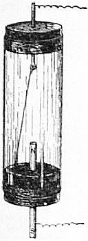
Fig. 1.
In 1825 another important step forward was taken when William Sturgeon (1783-1850) of London produced the electromagnet. It consisted of a horseshoe-shaped bar of soft iron, coated with varnish, on which was wrapped a spiral coil of bare copper wire, the turns not touching each other. When a voltaic current was passed through the wire the iron became a powerful magnet, but on severing the connexion with the battery, the soft iron lost immediately nearly all its magnetism.2
At that date Ohm had not announced his law of the electric circuit, and it was a matter of some surprise to investigators to find that Sturgeon’s electromagnet could not be operated at a distance through a long circuit of wire with such good results as when close to the battery. Peter Barlow, in January 1825, published in the Edinburgh Philosophical Journal, a description of such an experiment made with a view of applying Sturgeon’s electromagnet to telegraphy, with results which were unfavourable. Sturgeon’s experiments, however, stimulated Joseph Henry (q.v.) in the United States, and in 1831 he gave a description of a method of winding electromagnets which at once put a new face upon matters (Silliman’s Journal, 1831, 19, p. 400). Instead of insulating the iron core, he wrapped the copper wire round with silk and wound in numerous turns and many layers upon the iron horseshoe in such fashion that the current went round the iron always in the same direction. He then found that such an electromagnet wound with a long fine wire, if worked with a battery consisting of a large number of cells in series, could be operated at a considerable distance, and he thus produced what were called at that time intensity electromagnets, and which subsequently rendered the electric telegraph a possibility. In fact, Henry established in 1831, in Albany, U.S.A., an electromagnetic telegraph, and in 1835 at Princeton even used an earth return, thereby anticipating the discovery (1838) of C.A. Steinheil (1801-1870) of Munich.
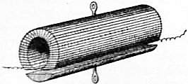
Fig. 2.
Inventors were then incited to construct powerful electromagnets as tested by the weight they could carry from their armatures. Joseph Henry made a magnet for Yale College, U.S.A., which lifted 3000 ℔ (Silliman’s Journal, 1831, 20, p. 201), and one for Princeton which lifted 3000 with a very small battery. Amongst others J.P. Joule, ever memorable for his investigations on the mechanical equivalent of heat, gave much attention about 1838-1840 to the construction of electromagnets and succeeded in devising some forms remarkable for their lifting power. One form was constructed by cutting a thick soft iron tube longitudinally into two equal parts. Insulated copper wire was then wound longitudinally over one of both parts (see fig. 2) and a current sent through the wire. In another form two iron disks with teeth at right angles to the disk had insulated wire wound zigzag between the teeth; when a current was sent through the wire, the teeth were so magnetized that they were alternately N. and S. poles. If two such similar disks were placed with teeth of opposite polarity in contact, a very large force was required to detach them, and with a magnet and armature weighing in all 11.575 ℔ Joule found that a weight of 2718 was supported. Joule’s papers on this subject will be found in his Collected Papers published by the Physical Society of London, and in Sturgeon’s Annals of Electricity, 1838-1841, vols. 2-6.
The Magnetic Circuit.—The phenomena presented by the electromagnet are interpreted by the aid of the notion of the magnetic circuit. Let us consider a thin circular sectioned ring of iron wire wound over with a solenoid or spiral of insulated copper wire through which a current of electricity can be passed. If the solenoid or wire windings existed alone, a current having a strength A amperes passed through it would create in the interior of the solenoid a magnetic force H, numerically equal to 4π/10 multiplied by the number of windings N on the solenoid, and by the current in amperes A, and divided by the mean length of the solenoid l, or H = 4πAN/10l. The product AN is called the “ampere-turns” on the solenoid. The product Hl of the magnetic force H and the length l of the magnetic circuit is called the “magnetomotive force” in the magnetic circuit, and from the above formula it is seen that the magnetomotive force denoted by (M.M.F.) is equal to 4π/10 (= 1.25 nearly) times the ampere-turns (A.N.) on the exciting coil or solenoid. Otherwise (A.N.) = 0.8(M.M.F.). The magnetomotive force is regarded as creating an effect called magnetic flux (Z) in the magnetic circuit, just as electromotive force E.M.F. produces electric current (A) in the electric circuit, and as by Ohm’s law (see Electrokinetics) the current varies as the E.M.F. and inversely as a quality of the electric circuit called its “resistance,” so in the magnetic circuit the magnetic flux varies as the magnetomotive force and inversely as a quality of the magnetic circuit called its “reluctance.” The great difference between the electric circuit and the magnetic circuit lies in the fact that whereas the electric resistance of a solid or liquid conductor is independent of the current and affected only by the temperature, the magnetic reluctance varies with the magnetic flux and cannot be defined except by means of a curve which shows its value for different flux densities. The quotient of the total magnetic flux, Z, in a circuit by the cross section, S, of the circuit is called the mean “flux density,” and the reluctance of a magnetic circuit one centimetre long and one square centimetre in cross section is called the “reluctivity” of the material. The relation between reluctivity ρ = 1/μ magnetic force H, and flux density B, is defined by the equation H = ρB, from which we have Hl = Z (ρl/S) = M.M.F. acting on the circuit. Again, since the ampere-turns (AN) on the circuit are equal to 0.8 times the M.M.F., we have finally AN/l = 0.8(Z/μS). This equation tells us the exciting force reckoned in ampere-turns, AN, which must be put on the ring core to create a total magnetic flux Z in it, the ring core having a mean perimeter l and cross section S and reluctivity ρ = 1/μ corresponding to a flux density Z/S. Hence before we can make use of the equation for practical purposes we need to possess a curve for the particular material showing us the value of the reluctivity corresponding to various values of the possible flux density. The reciprocal of ρ is usually called the “permeability” of the material and denoted by μ. Curves showing the relation of 1/ρ and ZS or μ and B, are called “permeability curves.” For air and all other non-magnetic matter the permeability has the same value, taken arbitrarily as unity. On the other hand, for iron, nickel and cobalt the permeability may in some cases reach a value of 2000 or 2500 for a value of B = 5000 in C.G.S. measure (see Units, Physical). The process of taking these curves consists in sending a current of known strength through a solenoid of known number of turns wound on a circular iron ring of known dimensions, and observing the time-integral of the secondary current produced in a secondary circuit of known turns and resistance R wound over the iron core N times. The secondary electromotive force is by Faraday’s law (see Electrokinetics) equal to the time rate of change of the total flux, or E = NdZ/dt. But by Ohm’s law E = Rdq/dt, where q is the quantity of electricity set flowing in the secondary circuit by a change dZ in the co-linked total flux. Hence if 2Q represents this total quantity of electricity set flowing in the secondary circuit by suddenly reversing the direction of the magnetic flux Z in the iron core we must have
RQ = NZ or Z = RQ/N.
The measurement of the total quantity of electricity Q can be made by means of a ballistic galvanometer (q.v.), and the resistance R of the secondary circuit includes that of the coil wound on the iron core and the galvanometer as well. In this manner the value of the total flux Z and therefore of Z/S = B or the flux density, can be found for a given magnetizing force H, and this last quantity is determined when we know the magnetizing current in the solenoid and its turns and dimensions. The curve which delineates the relation of H and B is called the magnetization curve for the material in question. For examples of these curves see Magnetism.
The fundamental law of the non-homogeneous magnetic circuit traversed by one and the same total magnetic flux Z is that the sum of all the magnetomotive forces acting in the circuit is numerically equal to the product of the factor 0.8, the total flux in the circuit, and the sum of all the reluctances of the various parts of the circuit. If then the circuit consists of materials of different permeability and it is desired to know the ampere-turns required to produce a given total of flux round the circuit, we have to calculate from the magnetization curves of the material of each part the necessary magnetomotive forces and add these forces together. The practical application of this principle to the predetermination of the field windings of dynamo magnets was first made by Drs J. and E. Hopkinson (Phil. Trans., 1886, 177, p. 331).
We may illustrate the principles of this predetermination by a simple example. Suppose a ring of iron has a mean diameter of 10 cms. and a cross section of 2 sq. cms., and a transverse cut on air gap made in it 1 mm. wide. Let us inquire the ampere-turns to be put upon the ring to create in it a total flux of 24,000 C.G.S. units. The total length of the iron part of the circuit is (10π − 0.1) cms., and its section is 2 sq. cms., and the flux density in it is to be 12,000. From Table II. below we see that the permeability of pure iron corresponding to a flux density of 12,000 is 2760. Hence the reluctance of the iron circuits is equal to
10π − 0.1 = 220 C.G.S. units.
2760 × 2 38640
The length of the air gap is 0.1 cm., its section 2 sq. cms., and its permeability is unity. Hence the reluctance of the air gap is
0.1 = 1 C.G.S. unit.
1 × 2 20
Accordingly the magnetomotive force in ampere-turns required to produce the required flux is equal to
0.8 (24,000) ( 1 + 220 ) = 1070 nearly.
20 38640
It follows that the part of the magnetomotive force required to overcome the reluctance of the narrow air gap is about nine times that required for the iron alone.
In the above example we have for simplicity assumed that the flux in passing across the air gap does not spread out at all. In dealing with electromagnet design in dynamo construction we have, however, to take into consideration the spreading as well as the leakage of flux across the circuit (see Dynamo). It will be seen, therefore, that in order that we may predict the effect of a certain kind of iron or steel when used as the core of an electromagnet, we must be provided with tables or curves showing the reluctivity or permeability corresponding to various flux densities or—which comes to the same thing—with (B, H) curves for the sample.
Iron and Steel for Electromagnetic Machinery.—In connexion with the technical application of electromagnets such as those used in the field magnets of dynamos (q.v.), the testing of different kinds of iron and steel for magnetic permeability has therefore become very important. Various instruments called permeameters and hysteresis meters have been designed for this purpose, but much of the work has been done by means of a ballistic galvanometer and test ring as above described. The “hysteresis” of an iron or steel is that quality of it in virtue of which energy is dissipated as heat when the magnetization is reversed or carried through a cycle (see Magnetism), and it is generally measured either in ergs per cubic centimetre of metal per cycle of magnetization, or in watts per ℔ per 50 or 100 cycles per second at or corresponding to a certain maximum flux density, say 2500 or 600 C.G.S. units. For the details of various forms of permeameter and hysteresis meter technical books must be consulted.3
An immense number of observations have been carried out on the magnetic permeability of different kinds of iron and steel, and in the following tables are given some typical results, mostly from experiments made by J.A. Ewing (see Proc. Inst. C.E., 1896, 126, p. 185) in which the ballistic method was employed to determine the flux density corresponding to various magnetizing forces acting upon samples of iron and steel in the form of rings.
The figures under heading I. are values given in a paper by A.W.S. Pocklington and F. Lydall (Proc. Roy. Soc., 1892-1893, 52, pp. 164 and 228) as the results of a magnetic test of an exceptionally pure iron supplied for the purpose of experiment by Colonel Dyer, of the Elswick Works. The substances other than iron in this sample were stated to be: carbon, trace; silicon, trace; phosphorus, none; sulphur, 0.013%; manganese, 0.1%. The other five specimens, II. to VI., are samples of commercial iron or steel. No. II. is a sample of Low Moor bar iron forged into a ring, annealed and turned. No. III. is a steel forging furnished by Mr R. Jenkins as a sample of forged ingot-metal for dynamo magnets. No. IV. is a steel casting for dynamo magnets, unforged, made by Messrs Edgar Allen & Company by a special pneumatic process under the patents of Mr A. Tropenas. No. V. is also an unforged steel casting for dynamo magnets, made by Messrs Samuel Osborne & Company by the Siemens process. No. VI. is also an unforged steel casting for dynamo magnets, made by Messrs Fried. Krupp, of Essen.
Table I.—Magnetic Flux Density corresponding to various Magnetizing Forces in the case of certain Samples of Iron and Steel (Ewing).
Magnetizing Force H (C.G.S. Units). Magnetic Flux Density B (C.G.S. Units).
I. II. III. IV. V. VI.
5 12,700 10,900 12,300 4,700 9,600 10,900
10 14,980 13,120 14,920 12,250 13,050 13,320
15 15,800 14,010 15,800 14,000 14,600 14,350
20 16,300 14,580 16,280 15,050 15,310 14,950
30 16,950 15,280 16,810 16,200 16,000 15,660
40 17,350 15,760 17,190 16,800 16,510 16,150
50 · · 16,060 17,500 17,140 16,900 16,480
60 · · 16,340 17,750 17,450 17,180 16,780
70 · · 16,580 17,970 17,750 17,400 17,000
80 · · 16,800 18,180 18,040 17,620 17,200
90 · · 17,000 18,390 18,230 17,830 17,400
100 · · 17,200 18,600 18,420 18,030 17,600
It will be seen from the figures and the description of the materials that the steel forgings and castings have a remarkably high permeability under small magnetizing force.
Table II. shows the magnetic qualities of some of these materials as found by Ewing when tested with small magnetizing forces.
Table II.—Magnetic Permeability of Samples of Iron and Steel under Weak Magnetizing Forces.
Magnetic Flux Density B (C.G.S. Units). I. Pure Iron. III. Steel Forging. VI. Steel Casting.
H μ H μ H μ
2,000 0.90 2220 1.38 1450 1.18 1690
4,000 1.40 2850 1.91 2090 1.66 2410
6,000 1.85 3240 2.38 2520 2.15 2790
8,000 2.30 3480 2.92 2740 2.83 2830
10,000 3.10 3220 3.62 2760 4.05 2470
12,000 4.40 2760 4.80 2500 6.65 1810
The numbers I., III. and VI. in the above table refer to the samples mentioned in connexion with Table I.
It is a remarkable fact that certain varieties of low carbon steel (commonly called mild steel) have a higher permeability than even annealed Swedish wrought iron under large magnetizing forces. The term steel, however, here used has reference rather to the mode of production than the final chemical nature of the material. In some of the mild-steel castings used for dynamo electromagnets it appears that the total foreign matter, including carbon, manganese and silicon, is not more than 0.3% of the whole, the material being 99.7% pure iron. This valuable magnetic property of steel capable of being cast is, however, of great utility in modern dynamo building, as it enables field magnets of very high permeability to be constructed, which can be fashioned into shape by casting instead of being built up as formerly out of masses of forged wrought iron. The curves in fig. 3 illustrate the manner in which the flux density or, as it is usually called, the magnetization curve of this mild cast steel crosses that of Swedish wrought iron, and enables us to obtain a higher flux density corresponding to a given magnetizing force with the steel than with the iron.
From the same paper by Ewing we extract a number of results relating to permeability tests of thin sheet iron and sheet steel, such as is used in the construction of dynamo armatures and transformer cores.
No. VII. is a specimen of good transformer-plate, 0.301 millimetre thick, rolled from Swedish iron by Messrs Sankey of Bilston. No. VIII. is a specimen of specially thin transformer-plate rolled from scrap iron. No. IX. is a specimen of transformer-plate rolled from ingot-steel. No. X. is a specimen of the wire which was used by J. Swinburne to form the core of his “hedgehog” transformers. Its diameter was 0.602 millimetre. All these samples were tested in the form of rings by the ballistic method, the rings of sheet-metal being stamped or turned in the flat. The wire ring No. X. was coiled and annealed after coiling.
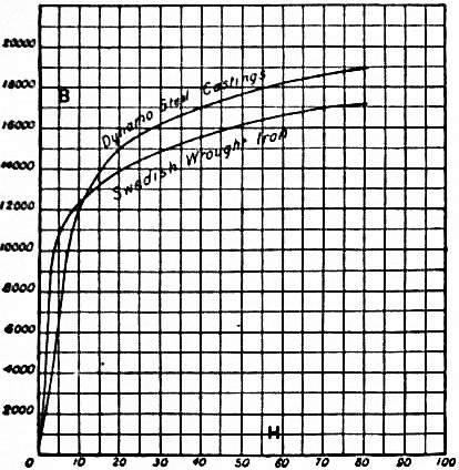
Fig. 3.
Table III.—Permeability Tests of Transformer Plate and Wire.
Magnetic Flux Density B (C.G.S. Units). VII. Transformer- plate of Swedish Iron. VIII. Transformer- plate of Scrap Iron. IX. Transformer- plate of of Steel. X. Transformer- wire.
H μ H μ H μ H μ
1,000 0.81 1230 1.08 920 0.60 1470 1.71 590
2,000 1.05 1900 1.46 1370 0.90 2230 2.10 950
3,000 1.26 2320 1.77 1690 1.04 2880 2.30 1300
4,000 1.54 2600 2.10 1900 1.19 3360 2.50 1600
5,000 1.82 2750 2.53 1980 1.38 3620 2.70 1850
6,000 2.14 2800 3.04 1970 1.59 3770 2.92 2070
7,000 2.54 2760 3.62 1930 1.89 3700 3.16 2210
8,000 3.09 2590 4.37 1830 2.25 3600 3.43 2330
9,000 3.77 2390 5.3 1700 2.72 3310 3.77 2390
10,000 4.6 2170 6.5 1540 3.33 3000 4.17 2400
11,000 5.7 1930 7.9 1390 4.15 2650 4.70 2340
12,000 7.0 1710 9.8 1220 5.40 2220 5.45 2200
13,000 8.5 1530 11.9 1190 7.1 1830 6.5 2000
14,000 11.0 1270 15.0 930 10.0 1400 8.4 1670
15,000 15.1 990 19.5 770 · · · · 11.9 1260
16,000 21.4 750 27.5 580 · · · · 21.0 760
Some typical flux-density curves of iron and steel as used in dynamo and transformer building are given in fig. 4.
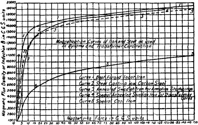
Fig. 4.
The numbers in Table III. well illustrate the fact that the permeability, μ = B/H has a maximum value corresponding to a certain flux density. The tables are also explanatory of the fact that mild steel has gradually replaced iron in the manufacture of dynamo electromagnets and transformer-cores.
Broadly speaking, the materials which are now employed in the manufacture of the cores of electromagnets for technical purposes of various kinds may be said to fall into three classes, namely, forgings, castings and stampings. In some cases the iron or steel core which is to be magnetized is simply a mass of iron hammered or pressed into shape by hydraulic pressure; in other cases it has to be fused and cast; and for certain other purposes it must be rolled first into thin sheets, which are subsequently stamped out into the required forms.
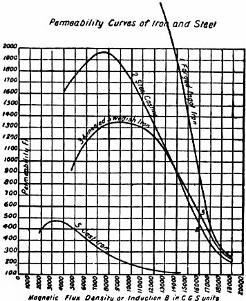
Fig. 5.
For particular purposes it is necessary to obtain the highest possible magnetic permeability corresponding to a high, or the highest attainable flux density. This is generally the case in the electromagnets which are employed as the field magnets in dynamo machines. It may generally be said that whilst the best wrought iron, such as annealed Low Moor or Swedish iron, is more permeable for low flux densities than steel castings, the cast steel may surpass the wrought metal for high flux density. For most electro-technical purposes the best magnetic results are given by the employment of forged ingot-iron. This material is probably the most permeable throughout the whole scale of attainable flux densities. It is slightly superior to wrought iron, and it only becomes inferior to the highest class of cast steel when the flux density is pressed above 18,000 C.G.S. units (see fig. 5). For flux densities above 13,000 the forged ingot-iron has now practically replaced for electric engineering purposes the Low Moor or Swedish iron. Owing to the method of its production, it might in truth be called a soft steel with a very small percentage of combined carbon. The best description of this material is conveyed by the German term “Flusseisen,” but its nearest British equivalent is “ingot-iron.” Chemically speaking, the material is for all practical purposes very nearly pure iron. The same may be said of the cast steels now much employed for the production of dynamo magnet cores. The cast steel which is in demand for this purpose has a slightly lower permeability than the ingot-iron for low flux densities, but for flux densities above 16,000 the required result may be more cheaply obtained with a steel casting than with a forging. When high tensile strength is required in addition to considerable magnetic permeability, it has been found advantageous to employ a steel containing 5% of nickel. The rolled sheet iron and sheet steel which is in request for the construction of magnet cores, especially those in which the exciting current is an alternating current, are, generally speaking, produced from Swedish iron. Owing to the mechanical treatment necessary to reduce the material to a thin sheet, the permeability at low flux densities is rather higher than, although at high flux densities it is inferior to, the same iron and steel when tested in bulk. For most purposes, however, where a laminated iron magnet core is required, the flux density is not pressed up above 6000 units, and it is then more important to secure small hysteresis loss than high permeability. The magnetic permeability of cast iron is much inferior to that of wrought or ingot-iron, or the mild steels taken at the same flux densities.
The following Table IV. gives the flux density and permeability of a typical cast iron taken by J.A. Fleming by the ballistic method:—
Table IV.—Magnetic Permeability and Magnetization Curve of Cast Iron.
H B μ H B μ H B μ
.19 27 139 8.84 4030 456 44.65 8,071 181
.41 62 150 10.60 4491 424 56.57 8,548 151
1.11 206 176 12.33 4884 396 71.98 9,097 126
2.53 768 303 13.95 5276 378 88.99 9,600 108
3.41 1251 367 15.61 5504 353 106.35 10,066 95
4.45 1898 427 18.21 5829 320 120.60 10,375 86
5.67 2589 456 26.37 6814 258 140.37 10,725 76
7.16 3350 468 36.54 7580 207 152.73 10,985 72
The metal of which the tests are given in Table IV. contained 2% of silicon, 2.85% of total carbon, and 0.5% of manganese. It will be seen that a magnetizing force of about 5 C.G.S. units is sufficient to impart to a wrought-iron ring a flux density of 18,000 C.G.S. units, but the same force hardly produces more than one-tenth of this flux density in cast iron.
The testing of sheet iron and steel for magnetic hysteresis loss has developed into an important factory process, giving as it does a means of ascertaining the suitability of the metal for use in the manufacture of transformers and cores of alternating-current electromagnets.
In Table V. are given the results of hysteresis tests by Ewing on samples of commercial sheet iron and steel. The numbers VII., VIII., IX. and X. refer to the same samples as those for which permeability results are given in Table III.
Table V.—Hysteresis Loss in Transformer-iron.
Maximum Flux Density B. Ergs per Cubic Centimetre per Cycle. Watts per ℔ at a Frequency of 100.
VII. Swedish Iron. VIII. Forged Scrap- iron. IX. Ingot- steel. X. Soft Iron Wire. VII. VIII. IX. X.
2000 240 400 215 600 0.141 0.236 0.127 0.356
3000 520 790 430 1150 0.306 0.465 0.253 0.630
4000 830 1220 700 1780 0.490 0.720 0.410 1.050
5000 1190 1710 1000 2640 0.700 1.010 0.590 1.550
6000 1600 2260 1350 3360 0.940 1.330 0.790 1.980
7000 2020 2940 1730 4300 1.200 1.730 1.020 2.530
8000 2510 3710 2150 5300 1.480 2.180 1.270 3.120
9000 3050 4560 2620 6380 1.800 2.680 1.540 3.750
In Table VI. are given the results of a magnetic test of some exceedingly good transformer-sheet rolled from Swedish iron.
Table VI.—Hysteresis Loss in Strip of Transformer-plate rolled Swedish Iron.
Maximum Flux Density B. Ergs per Cubic Centimetre per Cycle. Watts per ℔ at a Frequency of 100.
2000 220 0.129
3000 410 0.242
4000 640 0.376
5000 910 0.535
6000 1200 0.710
7000 1520 0.890
8000 1900 1.120
9000 2310 1.360
In Table VII. are given some values obtained by Fleming for the hysteresis loss in the sample of cast iron, the permeability test of which is recorded in Table IV.
Table VII.—Observations on the Magnetic Hysteresis of Cast Iron.
Loop. B (max.) Hysteresis Loss.
Ergs per cc. per Cycle. Watts per ℔ per. 100 Cycles per sec.
I. 1475 466 .300
II. 2545 1,288 .829
III. 3865 2,997 1.934
IV. 5972 7,397 4.765
V. 8930 13,423 8.658
For most practical purposes the constructor of electromagnetic machinery requires his iron or steel to have some one of the following characteristics. If for dynamo or magnet making, it should have the highest possible permeability at a flux density corresponding to practically maximum magnetization. If for transformer or alternating-current magnet building, it should have the smallest possible hysteresis loss at a maximum flux density of 2500 C.G.S. units during the cycle. If required for permanent magnet making, it should have the highest possible coercivity combined with a high retentivity. Manufacturers of iron and steel are now able to meet these demands in a very remarkable manner by the commercial production of material of a quality which at one time would have been considered a scientific curiosity.
It is usual to specify iron and steel for the first purpose by naming the minimum permeability it should possess corresponding to a flux density of 18,000 C.G.S. units; for the second, by stating the hysteresis loss in watts per ℔ per 100 cycles per second, corresponding to a maximum flux density of 2500 C.G.S. units during the cycle; and for the third, by mentioning the coercive force required to reduce to zero magnetization a sample of the metal in the form of a long bar magnetized to a stated magnetization. In the cyclical reversal of magnetization of iron we have two modes to consider. In the first case, which is that of the core of the alternating transformer, the magnetic force passes through a cycle of values, the iron remaining stationary, and the direction of the magnetic force being always the same. In the other case, that of the dynamo armature core, the direction of the magnetic force in the iron is constantly changing, and at the same time undergoing a change in magnitude.
It has been shown by F.G. Baily (Proc. Roy. Soc., 1896) that if a mass of laminated iron is rotating in a magnetic field which remains constant in direction and magnitude in any one experiment, the hysteresis loss rises to a maximum as the magnitude of the flux density in the iron is increased and then falls away again to nearly zero value. These observations have been confirmed by other observers. The question has been much debated whether the values of the hysteresis loss obtained by these two different methods are identical for magnetic cycles in which the flux density reaches the same maximum value. This question is also connected with another one, namely, whether the hysteresis loss per cycle is or is not a function of the speed with which the cycle is traversed. Early experiments by C.P. Steinmetz and others seemed to show that there was a difference between slow-speed and high-speed hysteresis cycles, but later experiments by J. Hopkinson and by A. Tanakadaté, though not absolutely exhaustive, tend to prove that up to 400 cycles per second the hysteresis loss per cycle is practically unchanged.
Experiments made in 1896 by R. Beattie and R.C. Clinker on magnetic hysteresis in rotating fields were partly directed to determine whether the hysteresis loss at moderate flux densities, such as are employed in transformer work, was the same as that found by measurements made with alternating-current fields on the same iron and steel specimens (see The Electrician, 1896, 37, p. 723). These experiments showed that over moderate ranges of induction, such as may be expected in electro-technical work, the hysteresis loss per cycle per cubic centimetre was practically the same when the iron was tested in an alternating field with a periodicity of 100, the field remaining constant in direction, and when the iron was tested in a rotating field giving the same maximum flux density.
With respect to the variation of hysteresis loss in magnetic cycles having different maximum values for the flux density, Steinmetz found that the hysteresis loss (W), as measured by the area of the complete (B, H) cycle and expressed in ergs per centimetre-cube per cycle, varies proportionately to a constant called the hysteretic constant, and to the 1.6th power of the maximum flux density (B), or W = ηB1.6.
The hysteretic constants (η) for various kinds of iron and steel are given in the table below:—
Metal. Hysteretic Constant.
Swedish wrought iron, well annealed .0010 to .0017
Annealed cast steel of good quality; small
percentage of carbon .0017 to .0029
Cast Siemens-Martin steel .0019 to .0028
Cast ingot-iron .0021 to .0026
Cast steel, with higher percentages of carbon,
or inferior qualities of wrought iron .0031 to .0054
Steinmetz’s law, though not strictly true for very low or very high maximum flux densities, is yet a convenient empirical rule for obtaining approximately the hysteresis loss at any one maximum flux density and knowing it at another, provided these values fall within a range varying say from 1 to 9000 C.G.S. units. (See Magnetism.)
The standard maximum flux density which is adopted in electro-technical work is 2500, hence in the construction of the cores of alternating-current electromagnets and transformers iron has to be employed having a known hysteretic constant at the standard flux density. It is generally expressed by stating the number of watts per ℔ of metal which would be dissipated for a frequency of 100 cycles, and a maximum flux density (B max.) during the cycle of 2500. In the case of good iron or steel for transformer-core making, it should not exceed 1.25 watt per ℔ per 100 cycles per 2500 B (maximum value).
It has been found that if the sheet iron employed for cores of alternating electromagnets or transformers is heated to a temperature somewhere in the neighbourhood of 200° C. the hysteresis loss is very greatly increased. It was noticed in 1894 by G.W. Partridge that alternating-current transformers which had been in use some time had a very considerably augmented core loss when compared with their initial condition. O.T. Bláthy and W.M. Mordey in 1895 showed that this augmentation in hysteresis loss in iron was due to heating. H.F. Parshall investigated the effect up to moderate temperatures, such as 140° C., and an extensive series of experiments was made in 1898 by S.R. Roget (Proc. Roy. Soc., 1898, 63, p. 258, and 64, p. 150). Roget found that below 40° C. a rise in temperature did not produce any augmentation in the hysteresis loss in iron, but if it is heated to between 40° C. and 135° C. the hysteresis loss increases continuously with time, and this increase is now called “ageing” of the iron. It proceeds more slowly as the temperature is higher. If heated to above 135° C., the hysteresis loss soon attains a maximum, but then begins to decrease. Certain specimens heated to 160° C. were found to have their hysteresis loss doubled in a few days. The effect seems to come to a maximum at about 180° C. or 200° C. Mere lapse of time does not remove the increase, but if the iron is reannealed the augmentation in hysteresis disappears. If the iron is heated to a higher temperature, say between 300° C. and 700° C., Roget found the initial rise of hysteresis happens more quickly, but that the metal soon settles down into a state in which the hysteresis loss has a small but still augmented constant value. The augmentation in value, however, becomes more nearly zero as the temperature approaches 700° C. Brands of steel are now obtainable which do not age in this manner, but these non-ageing varieties of steel have not generally such low initial hysteresis values as the “Swedish Iron,” commonly considered best for the cores of transformers and alternating-current magnets.
The following conclusions have been reached in the matter:—(1) Iron and mild steel in the annealed state are more liable to change their hysteresis value by heating than when in the harder condition; (2) all changes are removed by re-annealing; (3) the changes thus produced by heating affect not only the amount of the hysteresis loss, but also the form of the lower part of the (B, H) curve.
Forms of Electromagnet.—The form which an electromagnet must take will greatly depend upon the purposes for which it is to be used. A design or form of electromagnet which will be very suitable for some purposes will be useless for others. Supposing it is desired to make an electromagnet which shall be capable of undergoing very rapid changes of strength, it must have such a form that the coercivity of the material is overcome by a self-demagnetizing force. This can be achieved by making the magnet in the form of a short and stout bar rather than a long thin one. It has already been explained that the ends or poles of a polar magnet exert a demagnetizing power upon the mass of the metal in the interior of the bar. If then the electromagnet has the form of a long thin bar, the length of which is several hundred times its diameter, the poles are very far removed from the centre of the bar, and the demagnetizing action will be very feeble; such a long thin electromagnet, although made of very soft iron, retains a considerable amount of magnetism after the magnetizing force is withdrawn. On the other hand, a very thick bar very quickly demagnetizes itself, because no part of the metal is far removed from the action of the free poles. Hence when, as in many telegraphic instruments, a piece of soft iron, called an armature, has to be attracted to the poles of a horseshoe-shaped electromagnet, this armature should be prevented from quite touching the polar surfaces of the magnet. If a soft iron mass does quite touch the poles, then it completes the magnetic circuit and abolishes the free poles, and the magnet is to a very large extent deprived of its self-demagnetizing power. This is the explanation of the well-known fact that after exciting the electromagnet and then stopping the current, it still requires a good pull to detach the “keeper”; but when once the keeper has been detached, the magnetism is found to have nearly disappeared. An excellent form of electromagnet for the production of very powerful fields has been designed by H. du Bois (fig. 6).
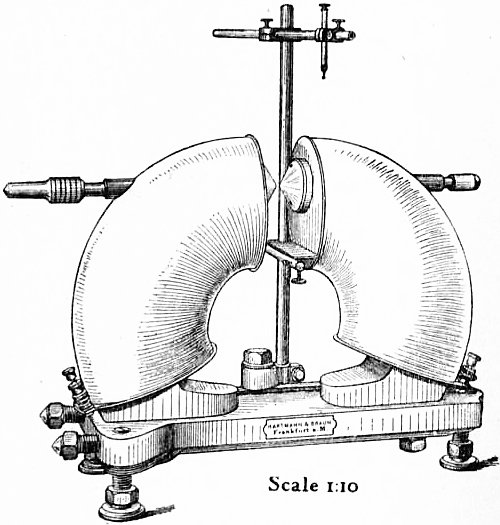
Fig. 6.—Du Bois’s Electromagnet.
Various forms of electromagnets used in connexion with dynamo machines are considered in the article Dynamo, and there is, therefore, no necessity to refer particularly to the numerous different shapes and types employed in electrotechnics.
Bibliography.—For additional information on the above subject the reader may be referred to the following works and original papers:—
H. du Bois, The Magnetic Circuit in Theory and Practice; S.P. Thompson, The Electromagnet; J.A. Fleming, Magnets and Electric Currents; J.A. Ewing, Magnetic Induction in Iron and other Metals; J.A. Fleming, “The Ferromagnetic Properties of Iron and Steel,” Proceedings of Sheffield Society of Engineers and Metallurgists (Oct. 1897); J.A. Ewing, “The Magnetic Testing of Iron and Steel,” Proc. Inst. Civ. Eng., 1896, 126, p. 185; H.F. Parshall, “The Magnetic Data of Iron and Steel,” Proc. Inst. Civ. Eng., 1896, 126, p. 220; J.A. Ewing, “The Molecular Theory of Induced Magnetism,” Phil. Mag., Sept. 1890; W.M. Mordey, “Slow Changes in the Permeability of Iron,” Proc. Roy. Soc. 57, p. 224; J.A. Ewing, “Magnetism,” James Forrest Lecture, Proc. Inst. Civ. Eng. 138; S.P. Thompson, “Electromagnetic Mechanism,” Electrician, 26, pp. 238, 269, 293; J.A. Ewing, “Experimental Researches in Magnetism,” Phil. Trans., 1885, part ii.; Ewing and Klassen, “Magnetic Qualities of Iron,” Proc. Roy. Soc., 1893.
(J. A. F.)
1 In the Annals of Philosophy for November 1821 is a long article entitled “Electromagnetism” by Oersted, in which he gives a detailed account of his discovery. He had his thoughts turned to it as far back as 1813, but not until the 20th of July 1820 had he actually made his discovery. He seems to have been arranging a compass needle to observe any deflections during a storm, and placed near it a platinum wire through which a galvanic current was passed.
2 See Trans. Soc. Arts, 1825, 43, p. 38, in which a figure of Sturgeon’s electromagnet is given as well as of other pieces of apparatus for which the Society granted him a premium and a silver medal.
3 See S.P. Thompson, The Electromagnet (London, 1891); J.A. Fleming, A Handbook for the Electrical Laboratory and Testing Room, vol. 2 (London, 1903); J.A. Ewing, Magnetic Induction in Iron and other Metals (London, 1903, 3rd ed.).
ELECTROMETALLURGY. The present article, as explained under Electrochemistry, treats only of those processes in which electricity is applied to the production of chemical reactions or molecular changes at furnace temperatures. In many of these the application of heat is necessary to bring the substances used into the liquid state for the purpose of electrolysis, aqueous solutions being unsuitable. Among the earliest experiments in this branch of the subject were those of Sir H. Davy, who in 1807 (Phil. Trans., 1808, p. 1), produced the alkali metals by passing an intense current of electricity from a platinum wire to a platinum dish, through a mass of fused caustic alkali. The action was started in the cold, the alkali being slightly moistened to render it a conductor; then, as the current passed, heat was produced and the alkali fused, the metal being deposited in the liquid condition. Later, A. Matthiessen (Quarterly Journ. Chem. Soc. viii. 30) obtained potassium by the electrolysis of a mixture of potassium and calcium chlorides fused over a lamp. There are here foreshadowed two types of electrolytic furnace-operations: (a) those in which external heating maintains the electrolyte in the fused condition, and (b) those in which a current-density is applied sufficiently high to develop the heat necessary to effect this object unaided. Much of the earlier electro-metallurgical work was done with furnaces of the (a) type, while nearly all the later developments have been with those of class (b). There is a third class of operations, exemplified by the manufacture of calcium carbide, in which electricity is employed solely as a heating agent; these are termed electrothermal, as distinguished from electrolytic. In certain electrothermal processes (e.g. calcium carbide production) the heat from the current is employed in raising mixtures of substances to the temperature at which a desired chemical reaction will take place between them, while in others (e.g. the production of graphite from coke or gas-carbon) the heat is applied solely to the production of molecular or physical changes. In ordinary electrolytic work only the continuous current may of course be used, but in electrothermal work an alternating current is equally available.
Electric Furnaces.—Independently of the question of the application of external heating, the furnaces used in electrometallurgy may be broadly classified into (i.) arc furnaces, in which the intense heat of the electric arc is utilized, and (ii.) resistance and incandescence furnaces, in which the heat is generated by an electric current overcoming the resistance of an inferior conductor.
Excepting such experimental arrangements as that of C.M. Despretz (C.R., 1849, 29) for use on a small scale in the laboratory, Pichou in France and J.H. Johnson in England appear, in 1853, to have introduced the earliest Arc furnaces. practical form of furnace. In these arrangements, which were similar if not identical, the furnace charge was crushed to a fine powder and passed through two or more electric arcs in succession. When used for ore smelting, the reduced metal and the accompanying slag were to be caught, after leaving the arc and while still liquid, in a hearth fired with ordinary fuel. Although this primitive furnace could be made to act, its efficiency was low, and the use of a separate fire was disadvantageous. In 1878 Sir William Siemens patented a form of furnace1 which is the type of a very large number of those designed by later inventors.
In the best-known form a plumbago crucible was used with a hole cut in the bottom to receive a carbon rod, which was ground in so as to make a tight joint. This rod was connected with the positive pole of the dynamo or electric generator. The crucible was fitted with a cover in which were two holes; one at the side to serve at once as sight-hole and charging door, the other in the centre to allow a second carbon rod to pass freely (without touching) into the interior. This rod was connected with the negative pole of the generator, and was suspended from one arm of a balance-beam, while from the other end of the beam was suspended a vertical hollow iron cylinder, which could be moved into or out of a wire coil or solenoid joined as a shunt across the two carbon rods of the furnace. The solenoid was above the iron cylinder, the supporting rod of which passed through it as a core. When the furnace with this well-known regulating device was to be used, say, for the melting of metals or other conductors of electricity, the fragments of metal were placed in the crucible and the positive electrode was brought near them. Immediately the current passed through the solenoid it caused the iron cylinder to rise, and, by means of its supporting rod, forced the end of the balance beam upwards, so depressing the other end that the negative carbon rod was forced downwards into contact with the metal in the crucible. This action completed the furnace-circuit, and current passed freely from the positive carbon through the fragments of metal to the negative carbon, thereby reducing the current through the shunt. At once the attractive force of the solenoid on the iron cylinder was automatically reduced, and the falling of the latter caused the negative carbon to rise, starting an arc between it and the metal in the crucible. A counterpoise was placed on the solenoid end of the balance beam to act against the attraction of the solenoid, the position of the counterpoise determining the length of the arc in the crucible. Any change in the resistance of the arc, either by lengthening, due to the sinking of the charge in the crucible, or by the burning of the carbon, affected the proportion of current flowing in the two shunt circuits, and so altered the position of the iron cylinder in the solenoid that the length of arc was, within limits, automatically regulated. Were it not for the use of some such device the arc would be liable to constant fluctuation and to frequent extinction. The crucible was surrounded with a bad conductor of heat to minimize loss by radiation. The positive carbon was in some cases replaced by a water-cooled metal tube, or ferrule, closed, of course, at the end inserted in the crucible. Several modifications were proposed, in one of which, intended for the heating of non-conducting substances, the electrodes were passed horizontally through perforations in the upper part of the crucible walls, and the charge in the lower part of the crucible was heated by radiation.
The furnace used by Henri Moissan in his experiments on reactions at high temperatures, on the fusion and volatilization of refractory materials, and on the formation of carbides, silicides and borides of various metals, consisted, in its simplest form, of two superposed blocks of lime or of limestone with a central cavity cut in the lower block, and with a corresponding but much shallower inverted cavity in the upper block, which thus formed the lid of the furnace. Horizontal channels were cut on opposite walls, through which the carbon poles or electrodes were passed into the upper part of the cavity. Such a furnace, to take a current of 4 H.P. (say, of 60 amperes and 50 volts), measured externally about 6 by 6 by 7 in., and the electrodes were about 0.4 in. in diameter, while for a current of 100 H.P. (say, of 746 amperes and 100 volts) it measured about 14 by 12 by 14 in., and the electrodes were about 1.5 in. in diameter. In the latter case the crucible, which was placed in the cavity immediately beneath the arc, was about 3 in. in diameter (internally), and about 3½ in. in height. The fact that energy is being used at so high a rate as 100 H.P. on so small a charge of material sufficiently indicates that the furnace is only used for experimental work, or for the fusion of metals which, like tungsten or chromium, can only be melted at temperatures attainable by electrical means. Moissan succeeded in fusing about ¾ ℔ of either of these metals in 5 or 6 minutes in a furnace similar to that last described. He also arranged an experimental tube-furnace by passing a carbon tube horizontally beneath the arc in the cavity of the lime blocks. When prolonged heating is required at very high temperatures it is found necessary to line the furnace-cavity with alternate layers of magnesia and carbon, taking care that the lamina next to the lime is of magnesia; if this were not done the lime in contact with the carbon crucible would form calcium carbide and would slag down, but magnesia does not yield a carbide in this way. Chaplet has patented a muffle or tube furnace, similar in principle, for use on a larger scale, with a number of electrodes placed above and below the muffle-tube. The arc furnaces now widely used in the manufacture of calcium carbide on a large scale are chiefly developments of the Siemens furnace. But whereas, from its construction, the Siemens furnace was intermittent in operation, necessitating stoppage of the current while the contents of the crucible were poured out, many of the newer forms are specially designed either to minimize the time required in effecting the withdrawal of one charge and the introduction of the next, or to ensure absolute continuity of action, raw material being constantly charged in at the top and the finished substance and by-products (slag, &c.) withdrawn either continuously or at intervals, as sufficient quantity shall have accumulated. In the King furnace, for example, the crucible, or lowest part of the furnace, is made detachable, so that when full it may be removed and an empty crucible substituted. In the United States a revolving furnace is used which is quite continuous in action.
The class of furnaces heated by electrically incandescent materials has been divided by Borchers into two groups: (1) those in which the substance is heated by contact with a substance offering a high resistance to the Incandescence furnaces. current passing through it, and (2) those in which the substance to be heated itself affords the resistance to the passage of the current whereby electric energy is converted into heat. Practically the first of these furnaces was that of Despretz, in which the mixture to be heated was placed in a carbon tube rendered incandescent by the passage of a current through its substance from end to end. In 1880 W. Borchers introduced his resistance-furnace, which, in one sense, is the converse of the Despretz apparatus. A thin carbon pencil, forming a bridge between two stout carbon rods, is set in the midst of the mixture to be heated. On passing a current through the carbon the small rod is heated to incandescence, and imparts heat to the surrounding mass. On a larger scale several pencils are used to make the connexions between carbon blocks which form the end walls of the furnace, while the side walls are of fire-brick laid upon one another without mortar. Many of the furnaces now in constant use depend mainly on this principle, a core of granular carbon fragments stamped together in the direct line between the electrodes, as in Acheson’s carborundum furnace, being substituted for the carbon pencils. In other cases carbon fragments are mixed throughout the charge, as in E.H. and A.H. Cowles’s zinc-smelting retort. In practice, in these furnaces, it is possible for small local arcs to be temporarily set up by the shifting of the charge, and these would contribute to the heating of the mass. In the remaining class of furnace, in which the electrical resistance of the charge itself is utilized, are the continuous-current furnaces, such as are used for the smelting of aluminium, and those alternating-current furnaces, (e.g. for the production of calcium carbide) in which a portion of the charge is first actually fused, and then maintained in the molten condition by the current passing through it, while the reaction between further portions of the charge is proceeding.
For ordinary metallurgical work the electric furnace, requiring as it does (excepting where waterfalls or other cheap sources of power are available) the intervention of the boiler and steam-engine, or of the gas or oil engine, with a Uses and advantages. consequent loss of energy, has not usually proved so economical as an ordinary direct fired furnace. But in some cases in which the current is used for electrolysis and for the production of extremely high temperatures, for which the calorific intensity of ordinary fuel is insufficient, the electric furnace is employed with advantage. The temperature of the electric furnace, whether of the arc or incandescence type, is practically limited to that at which the least easily vaporized material available for electrodes is converted into vapour. This material is carbon, and as its vaporizing point is (estimated at) over 3500° C., and less than 4000° C., the temperature of the electric furnace cannot rise much above 3500° C. (6330° F.); but H. Moissan showed that at this temperature the most stable of mineral combinations are dissociated, and the most refractory elements are converted into vapour, only certain borides, silicides and metallic carbides having been found to resist the action of the heat. It is not necessary that all electric furnaces shall be run at these high temperatures; obviously, those of the incandescence or resistance type may be worked at any convenient temperature below the maximum. The electric furnace has several advantages as compared with some of the ordinary types of furnace, arising from the fact that the heat is generated from within the mass of material operated upon, and (unlike the blast-furnace, which presents the same advantage) without a large volume of gaseous products of combustion and atmospheric nitrogen being passed through it. In ordinary reverberatory and other heating furnaces the burning fuel is without the mass, so that the vessel containing the charge, and other parts of the plant, are raised to a higher temperature than would otherwise be necessary, in order to compensate for losses by radiation, convection and conduction. This advantage is especially observed in some cases in which the charge of the furnace is liable to attack the containing vessel at high temperatures, as it is often possible to maintain the outer walls of the electric furnace relatively cool, and even to keep them lined with a protecting crust of unfused charge. Again, the construction of electric furnaces may often be exceedingly crude and simple; in the carborundum furnace, for example, the outer walls are of loosely piled bricks, and in one type of furnace the charge is simply heaped on the ground around the carbon resistance used for heating, without containing-walls of any kind. There is, however, one (not insuperable) drawback in the use of the electric furnace for the smelting of pure metals. Ordinarily carbon is used as the electrode material, but when carbon comes in contact at high temperatures with any metal that is capable of forming a carbide a certain amount of combination between them is inevitable, and the carbon thus introduced impairs the mechanical properties of the ultimate metallic product. Aluminium, iron, platinum and many other metals may thus take up so much carbon as to become brittle and unforgeable. It is for this reason that Siemens, Borchers and others substituted a hollow water-cooled metal block for the carbon cathode upon which the melted metal rests while in the furnace. Liquid metal coming in contact with such a surface forms a crust of solidified metal over it, and this crust thickens up to a certain point, namely, until the heat from within the furnace just overbalances that lost by conduction through the solidified crust and the cathode material to the flowing water. In such an arrangement, after the first instant, the melted metal in the furnace does not come in contact with the cathode material.