VOLUME IX SLICE II Ehud to Electroscope (continued 7)
Reading edition
K.W.
Continuous current 417,000 Provinces 333,000
London 84,000
Alternating current 132,000 Provinces 83,000
London 49,000
Continuous current and alternating current combined 480,000 Provinces 366,000
London 114,000
————
1,029,000 k.w.
The economics of electric lighting were at first assumed to be similar to those of gas lighting. Experience, however, soon proved that there were important differences, one being that gas may be stored in gasometers without Economics. appreciable loss and the work of production carried on steadily without reference to fluctuations of demand. Electricity cannot be economically stored to the same extent, and for the most part it has to be used as it is generated. The demand for electric light is practically confined to the hours between sunset and midnight, and it rises sharply to a “peak” during this period. Consequently the generating station has to be equipped with plant of sufficient capacity to cope with the maximum load, although the peak does not persist for many minutes—a condition which is very uneconomical both as regards capital expenditure and working costs (see Lighting: Electric). In order to obviate the unproductiveness of the generating plant during the greater part of the day, electricity supply undertakings sought to develop the “daylight” load. This they did by supplying electricity for traction purposes, but more particularly for industrial power purposes. The difficulties in the way of this line of development, however, were that electric power could not be supplied cheaply enough to compete with steam, hydraulic, gas and other forms of power, unless it was generated on a very large scale, and this large demand could not be developed within the restricted areas for which provisional orders were granted and under the restrictive conditions of these orders in regard to situation of power-house and other matters.
The leading factors which make for economy in electricity supply are the magnitude of the output, the load factor, and the diversity factor, also the situation of the power house, the means of distribution, and the provision of suitable, trustworthy and efficient plant. These factors become more favourable the larger the area and the greater and more varied the demand to be supplied. Generally speaking, as the output increases so the cost per unit diminishes, but the ratio (called the load factor) which the output during any given period bears to the maximum possible output during the same period has a very important influence on costs. The ideal condition would be when a power station is working at its normal maximum output continuously night and day. This would give a load-factor of 100%, and represents the ultimate ideal towards which the electrical engineer strives by increasing the area of his operations and consequently also the load and the variety of the overlapping demands. It is only by combining a large number of demands which fluctuate at different times—that is by achieving a high diversity factor—that the supplier of electricity can hope to approach the ideal of continuous and steady output. Owing to the dovetailing of miscellaneous demands the actual demand on a power station at any moment is never anything like the aggregate of all the maximum demands. One large station would require a plant of 36,000 k.w. capacity if all the demands came upon the station simultaneously, but the maximum demand on the generating plant is only 15,000 kilowatts. The difference between these two figures may be taken to represent the economy effected by combining a large number of demands on one station. In short, the keynote of progress in cheap electricity is increased and diversified demand combined with concentration of load. The average load-factor of all the British electricity stations in 1907 was 14.5%—a figure which tends to improve.
Several electric power supply companies have been established in the United Kingdom to give practical effect to these principles. The Electric Lighting Acts, however, do not provide for the establishment of large power companies, and Power companies. special acts of parliament have had to be promoted to authorize these undertakings. In 1898 several bills were introduced in parliament for these purposes. They were referred to a joint committee of both Houses of Parliament presided over by Lord Cross. The committee concluded that, where sufficient public advantages are shown, powers should be given for the supply of electricity over areas including the districts of several local authorities and involving the use of exceptional plant; that the usual conditions of purchase of the undertakings by the local authorities did not apply to such undertakings; that the period of forty-two years was “none too long” a tenure; and that the terms of purchase should be reconsidered. With regard to the provision of the Electric Lighting Acts which requires that the consent of the local authority should be obtained as a condition precedent to the granting of a provisional order, the committee was of opinion that the local authority should be entitled to be heard by the Board of Trade, but should not have the power of veto. No general legislation took place as a result of these recommendations, but the undermentioned special acts constituting power supply companies were passed.
In 1902 the president of the Board of Trade stated that a bill had been drafted which he thought “would go far to meet all the reasonable objections that had been urged against the present powers by the local authorities.” In 1904 the government introduced the Supply of Electricity Bill, which provided for the removal of some of the minor anomalies in the law relating to electricity. The bill passed through all its stages in the House of Lords but was not proceeded with in the House of Commons. In 1905 the bill was again presented to parliament but allowed to lie on the table. In the words of the president of the Board of Trade, there was “difficulty of dealing with this question so long as local authorities took so strong a view as to the power which ought to be reserved to them in connexion with this enterprise.” In the official language of the council of the Institution of Electrical Engineers, the development of electrical science in the United Kingdom is in a backward condition as compared with other countries in respect of the practical application to the industrial and social requirements of the nation, notwithstanding that Englishmen have been among the first in inventive genius. The cause of such backwardness is largely due to the conditions under which the electrical industry has been carried on in the country, and especially to the restrictive character of the legislation governing the initiation and development of electrical power and traction undertakings, and to the powers of obstruction granted to local authorities. Eventually The Electric Lighting Act 1909 was passed. This Act provides:—(1) for the granting of provisional orders authorizing any local authority or company to supply electricity in bulk; (2) for the exercise of electric lighting powers by local authorities jointly under provisional order; (3) for the supply of electricity to railways, canals and tramways outside the area of supply with the consent of the Board of Trade; (4) for the compulsory acquisition of land for generating stations by provisional order; (5) for the exemption of agreements for the supply of electricity from stamp duty; and (6) for the amendment of regulations relating to July notices, revision of maximum price, certification of meters, transfer of powers of undertakers, auditors’ reports, and other matters.
The first of the Power Bills was promoted in 1898, under which it was proposed to erect a large generating station in the Midlands from which an area of about two thousand square miles would be supplied. Vigorous opposition was organized against the bill by the local authorities and it did not pass. The bill was revived in 1899, but was finally crushed. In 1900 and following years several power bills were successfully promoted, and the following are the areas over which the powers of these acts extend:
In Scotland, (1) the Clyde Valley, (2) the county of Fife, (3) the districts described as “Scottish Central,” comprising Linlithgow, Clackmannan, and portions of Dumbarton and Stirling, and (4) the Lothians, which include portions of Midlothian, East Lothian, Peebles and Lanark.
In England there are companies operating in (1) Northumberland, (2) Durham county, (3) Lancashire, (4) South Wales and Carmarthenshire, (5) Derbyshire and Nottinghamshire, (6) Leicestershire and Warwickshire, (7) Yorkshire, (8) Shropshire, Worcestershire and Staffordshire, (9) Somerset, (10) Kent, (11) Cornwall, (12) portions of Gloucestershire, (13) North Wales, (14) North Staffordshire, Derbyshire, Denbighshire and Flintshire, (15) West Cumberland, (16) the Cleveland district, (17) the North Metropolitan district, and (18) the West Metropolitan area. An undertaking which may be included in this category, although it is not a Power Act company, is the Midland Electric Corporation in South Staffordshire. The systems of generation and distribution are generally 10,000 or 11,000 volts three-phase alternating current.
The powers conferred by these acts were much restricted as a result of opposition offered to them. In many cases the larger towns were cut out of the areas of supply altogether, but the general rule was that the power company was prohibited from supplying direct to a power consumer in the area of an authorized distributor without the consent of the latter, subject to appeal to the Board of Trade. Even this restricted power of direct supply was not embodied in all the acts, the power of taking supply in bulk being left only to certain authorized distributors and to authorized users such as railways and tramways. Owing chiefly to the exclusion of large towns and industrial centres from their areas, these power supply companies did not all prove as successful as was expected.
In the case of one of the power companies which has been in a favourable position for the development of its business, the theoretical conclusions in regard to the economy of large production above stated have been amply demonstrated in practice. In 1901, when this company was emerging from the stage of a simple electric lighting company, the total costs per unit were 1.05d. with an output of about 2½ million units per annum. In 1905 the output rose to over 30 million units mostly for power and traction purposes, and the costs fell to 0.56d. per unit.
An interesting phase of the power supply question has arisen in London. Under the general acts it was stipulated that the power-house should be erected within the area of supply, and amalgamation of undertakings was prohibited. After less than a decade of development several of the companies in London found themselves obliged to make considerable additions to their generating plants. But their existing buildings were full to their utmost capacity, and the difficulties of generating cheaply on crowded sites had increased instead of diminished during the interval. Several of the companies had to promote special acts of parliament to obtain relief, but the idea of a general combination was not considered to be within the range of practical politics until 1905, when the Administrative County of London Electric Power Bill was introduced. Compared with other large cities, the consumption of electricity in London is small. The output of electricity in New York for all purposes is 971 million units per annum or 282 units per head of population. The output of electricity in London is only 42 units per head per annum. There are in London twelve local authorities and fourteen companies carrying on electricity supply undertakings. The capital expenditure is £3,127,000 by the local authorities and £12,530,000 by the companies, and their aggregate capacity of plant is 165,000 k.w. The total output is about 160,000,000 units per annum, the total revenue is over £2,000,000, and the gross profit before providing for interest and sinking fund charges is £1,158,000. The general average cost of production is 1.55d. per unit, and the average price per unit sold is 3.16d., but some of the undertakers have already supplied electricity to large power consumers at below 1d. per unit. By generating on a large scale for a wide variety of demands the promoters of the new scheme calculated to be able to offer electrical energy in bulk to electricity supply companies and local authorities at prices substantially below their costs of production at separate stations, and also to provide them and power users with electricity at rates which would compete with other forms of power. The authorized capital was fixed at £6,666,000, and the initial outlay on the first plant of 90,000 k.w., mains, &c., was estimated at £2,000,000. The costs of generation were estimated at 0.15d. per unit, and the total cost at 0.52d. per unit sold. The output by the year 1911 was estimated at 133,500,000 units at an average selling price of 0.7d. per unit, to be reduced to 0.55d. by 1916 when the output was estimated at 600,000,000 units. The bill underwent a searching examination before the House of Lords committee and was passed in an amended form. At the second reading in the House of Commons a strong effort was made to throw it out, but it was allowed to go to committee on the condition—contrary to the general recommendations of the parliamentary committee of 1898—that a purchase clause would be inserted; but amendments were proposed to such an extent that the bill was not reported for third reading until the eve of the prorogation of parliament. In the following year (1906) the Administrative Company’s bill was again introduced in parliament, but the London County Council, which had previously adopted an attitude both hostile and negative, also brought forward a similar bill. Among other schemes, one known as the Additional Electric Power Supply Bill was to authorize the transmission of current from St Neots in Hunts. This bill was rejected by the House of Commons because the promoters declined to give precedence to the bill of the London County Council. The latter bill was referred to a hybrid committee with instructions to consider the whole question of London power supply, but it was ultimately rejected. The same result attended a second bill which was promoted by the London County Council in 1907. The question was settled by the London Electric Supply Act 1908, which constitutes the London County Council the purchasing authority (in the place of the local authorities) for the electric supply companies in London. This Act also enabled the Companies and other authorized undertakers to enter into agreements for the exchange of current and the linking-up of stations.
The general supply of electricity is governed primarily by the two acts of parliament passed in 1882 and 1888, which apply to the whole of the United Kingdom. Until 1899 the other statutory provisions relating to electricity supply were incorporated Legislation and regulations. in provisional orders granted by the Board of Trade and confirmed by parliament in respect of each undertaking, but in that year an Electric Lighting Clauses Act was passed by which the clauses previously inserted in each order were standardized. Under these acts the Board of Trade made rules with respect to applications for licences and provisional orders, and regulations for the protection of the public, and of the electric lines and works of the post office, and others, and also drew up a model form for provisional orders.
Until the passing of the Electric Lighting Acts, wires could be placed wherever permission for doing so could be obtained, but persons breaking up streets even with the consent of the local authority were liable to indictment for nuisance. With regard to overhead wires crossing the streets, the local authorities had no greater power than any member of the public, but a road authority having power to make a contract for lighting the road could authorize others to erect poles and wires for the purpose. A property owner, however, was able to prevent wires from being taken over his property. The act of 1888 made all electric lines or other works for the supply of electricity, not entirely enclosed within buildings or premises in the same occupation, subject to regulations of the Board of Trade. The postmaster-general may also impose conditions for the protection of the post office. Urban authorities, the London County Council, and some other corporations have now powers to make by-laws for prevention of obstruction from posts and overhead wires for telegraph, telephone, lighting or signalling purposes; and electric lighting stations are now subject to the provisions of the Factory Acts.
Parliamentary powers to supply electricity can now be obtained by (A) Special Act, (B) Licence, or (C) Provisional order.
A. Special Act.—Prior to the report of Lord Cross’s joint committee of 1898 (referred to above), only one special act was passed. The provisions of the Electric Power Acts passed subsequently are not uniform, but the following are some of the usual provisions:—
The company shall not supply electricity for lighting purposes except to authorized undertakers, provided that the energy supplied to any person for power may be used for lighting any premises on which the power is utilized. The company shall not supply energy (except to authorized undertakers) in any area which forms part of the area of supply of any authorized distributors without their consent, such consent not to be unreasonably withheld. The company is bound to supply authorized undertakers upon receiving notice and upon the applicants agreeing to pay for at least seven years an amount sufficient to yield 20% on the outlay (excluding generating plant or wires already installed). Other persons to whom the company is authorized to supply may require it upon terms to be settled, if not agreed, by the Board of Trade. Dividends are usually restricted to 8%, with a provision that the rate may be increased upon the average price charged being reduced. The maximum charges are usually limited to 3d. per unit for any quantity up to 400 hours’ supply, and 2d. per unit beyond. No preference is to be shown between consumers in like circumstances. Many provisions of the general Electric Lighting Acts are excluded from these special acts, in particular the clause giving the local authority the right to purchase the undertaking compulsorily.
B. Licence.—The only advantages of proceeding by licence are that it can be expeditiously obtained and does not require confirmation by parliament; but some of the provisions usually inserted in provisional orders would be ultra vires in a licence, and the Electric Lighting Clauses Act 1899 does not extend to licences. The term of a licence does not exceed seven years, but is renewable. The consent of the local authority is necessary even to an application for a licence. None of the licences that have been granted is now in force.
C. Provisional Order.—An intending applicant for a provisional order must serve notice of his intention on every local authority within the proposed area of supply on or before the 1st of July prior to the session in which application is to be made to the Board of Trade. This provision has given rise to much complaint, as it gives the local authorities a long time for bargaining and enables them to supersede the company’s application by themselves applying for provisional orders. The Board of Trade generally give preference to the applications of local authorities.
In 1905 the Board of Trade issued a memorandum stating that, in view of the revocation of a large number of provisional orders which had been obtained by local authorities, or in regard to which local authorities had entered into agreements with companies for carrying the orders into effect (which agreements were in many cases ultra vires or at least of doubtful validity), it appeared undesirable that a local authority should apply for a provisional order without having a definite intention of exercising the powers, and that in future the Board of Trade would not grant an order to a local authority unless the board were satisfied that the powers would be exercised within a specified period.
Every undertaking authorized by provisional order is subject to the provision of the general act entitling the local authority to purchase compulsorily at the end of forty-two years (or shorter period), or after the expiration of every subsequent period of ten years (unless varied by agreement between the parties with the consent of the Board of Trade), so much of the undertaking as is within the jurisdiction of the purchasing authority upon the terms of paying the then value of all lands, buildings, works, materials and plant, suitable to and used for the purposes of the undertaking; provided that the value of such lands, &c., shall be deemed to be their fair market value at the time of purchase, due regard being had to the nature and then condition and state of repair thereof, and to the circumstance that they are in such positions as to be ready for immediate working, and to the suitability of the same to the purposes of the undertaking, and where a part only of the undertaking is purchased, to any loss occasioned by severance, but without any addition in respect of compulsory purchase or of goodwill, or of any profits which may or might have been or be made from the undertaking or any similar consideration. Subject to this right of purchase by the local authority, a provisional order (but not a licence) may be for such period as the Board of Trade may think proper, but so far no limit has been imposed, and unless purchased by a local authority the powers are held in perpetuity. No monopoly is granted to undertakers, and since 1889 the policy of the Board of Trade has been to sanction two undertakings in the same metropolitan area, preferably using different systems, but to discourage competing schemes within the same area in the provinces. Undertakers must within two years lay mains in certain specified streets. After the first eighteen months they may be required to lay mains in other streets upon conditions specified in the order, and any owner or occupier of premises within 50 yds. of a distributing main may require the undertakers to give a supply to his premises; but the consumer must pay the cost of the lines laid upon his property and of so much outside as exceeds 60 ft. from the main, and he must also contract for two and in some cases for three years’ supply. But undertakers are prohibited in making agreements for supply from showing any undue preference. The maximum price in London is 13s. 4d. per quarter for any quantity up to 20 units, and beyond that 8d. per unit, but 11s. 8d. per quarter up to 20 units and 7d. per unit beyond is the more general maximum. The “Bermondsey clause” requires the undertakers (local authority) so to fix their charges (not exceeding the specified maximum) that the revenue shall not be less than the expenditure.
There is no statutory obligation on municipalities to provide for depreciation of electricity supply undertakings, but after providing for all expenses, interest on loans, and sinking fund instalments, the local authority may create a reserve fund until it amounts, with interest, to one-tenth of the aggregate capital expenditure. Any deficiency when not met out of reserve is payable out of the local rates.
The principle on which the Local Government Board sanctions municipal loans for electric lighting undertakings is that the period of the loan shall not exceed the life of the works, and that future ratepayers shall not be unduly burdened. The periods of the loans vary from ten years for accumulators and arc lamps to sixty years for lands. Within the county of London the loans raised by the metropolitan borough councils for electrical purposes are sanctioned by the London County Council, and that body allows a minimum period of twenty years for repayment. Up to 1904-1905, 245 loans had been granted by the council amounting in the aggregate to £4,045,067.
In 1901 the Institution of Civil Engineers appointed a committee to consider the advisability of standardizing various kinds of iron and steel sections. Subsequently the original reference was enlarged, and in 1902 the Standardization. Institution of Electrical Engineers was invited to co-operate. The treasury, as well as railway companies, manufacturers and others, have made grants to defray the expenses. The committee on electrical plant has ten sub-committees. In August 1904 an interim report was issued by the sub-committee on generators, motors and transformers, dealing with pressures and frequencies, rating of generators and motors, direct-current generators, alternating-current generators, and motors.
In 1903 the specification for British standard tramway rails and fish-plates was issued, and in 1904 a standard specification for tubular tramway poles was issued. A sectional committee was formed in 1904 to correspond with foreign countries with regard to the formation of an electrical international commission to study the question of an international standardization of nomenclature and ratings of electrical apparatus and machinery.
The electrical manufacturing branch, which is closely related to the electricity supply and other operating departments of the electrical industry, only dates from about 1880. Since that time it has undergone many vicissitudes. It The electrical industry. began with the manufacture of small arc lighting equipments for railway stations, streets and public buildings. When the incandescent lamp became a commercial article, ship-lighting sets and installations for theatres and mansions constituted the major portion of the electrical work. The next step was the organization of house-to-house distribution of electricity from small “central stations,” ultimately leading to the comprehensive public supply in large towns, which involved the manufacture of generating and distributing plants of considerable magnitude and complexity. With the advent of electric traction about 1896, special machinery had to be produced, and at a later stage the manufacturer had to solve problems in connexion with bulk supply in large areas and for power purposes. Each of these main departments involved changes in ancillary manufactures, such as cables, switches, transformers, meters, &c., so that the electrical manufacturing industry has been in a constant state of transition. At the beginning of the period referred to Germany and America were following the lead of England in theoretical developments, and for some time Germany obtained electrical machinery from England. Now scarcely any electrical apparatus is exported to Germany, and considerable imports are received by England from that country and America. The explanation is to be found mainly in the fact that the adverse legislation of 1882 had the effect of restricting enterprise, and while British manufacturers were compulsorily inert during periods of impeded growth of the two most important branches of the industry—electric lighting and traction—manufacturers in America and on the continent of Europe, who were in many ways encouraged by their governments, devoted their resources to the establishment of factories and electrical undertakings, and to the development of efficient selling organizations at home and abroad. When after the amendment of the adverse legislation in 1888 a demand for electrical machinery arose in England, the foreign manufacturers were fully organized for trade on a large scale, and were further aided by fiscal conditions to undersell English manufacturers, not only in neutral markets, but even in their own country. Successful manufacture on a large scale is possible only by standardizing the methods of production. English manufacturers were not able to standardize because they had not the necessary output. There had been no repetitive demand, and there was no production on a large scale. Foreign manufacturers, however, were able to standardize by reason of the large uniform demand which existed for their manufactures. Statistics are available showing the extent to which the growth of the electrical manufacturing industry in Great Britain was delayed. Nearly twenty years after the inception of the industry there were only twenty-four manufacturing companies registered in the United Kingdom, having an aggregate subscribed capital of under £7,000,000. But in 1907 there were 292 companies with over £42,000,000 subscribed capital. The cable and incandescent lamp sections show that when the British manufacturers are allowed opportunities they are not slow to take advantage of them. The cable-making branch was established under the more encouraging conditions of the telegraph industry, and the lamp industry was in the early days protected by patents. Other departments not susceptible to foreign competition on account of freightage, such as the manufacture of storage batteries and rolling stock, are also fairly prosperous. In departments where special circumstances offer a prospect of success, the technical skill, commercial enterprise and general efficiency of British manufacturers manifest themselves by positive progress and not merely by the continuance of a struggle against adverse conditions. The normal posture of the British manufacturer of electrical machinery has been described as one of desperate defence of his home trade; that of the foreign manufacturer as one of vigorous attack upon British and other open markets. In considering the position of English manufacturers as compared with their foreign rivals, some regard should be had to the patent laws. One condition of a grant of a patent in most foreign countries is that the patent shall be worked in those countries within a specified period. But a foreign inventor was until 1907 able to secure patent protection in Great Britain without any obligation to manufacture there. The effect of this was to encourage the manufacture of patented apparatus in foreign countries, and to stimulate their exportation to Great Britain in competition with British products. With regard to the electrochemical industry the progress which has been achieved by other nations, notably Germany, is very marvellous by comparison with the advance made by England, but to state the reasons why this industry has had such extraordinary development in Germany, notwithstanding that many of the fundamental inventions were made in England, would require a statement of the marked differences in the methods by which industrial progress is promoted in the two countries.
There has been very little solidarity among those interested in the commercial development of electricity, and except for the discussion of scientific subjects there has been very little organization with the object of protecting and promoting common interests.
(E. Ga.)
1 British Patent Specification, No. 5306 of 1878, and No. 602 of 1880.
2 Ibid. No. 3988 of 1878.
ELECTRIC WAVES. § 1. Clerk Maxwell proved that on his theory electromagnetic disturbances are propagated as a wave motion through the dielectric, while Lord Kelvin in 1853 (Phil. Mag. [4] 5, p. 393) proved from electromagnetic theory that the discharge of a condenser is oscillatory, a result which Feddersen (Pogg. Ann. 103, p. 69, &c.) verified by a beautiful series of experiments. The oscillating discharge of a condenser had been inferred by Henry as long ago as 1842 from his experiments on the magnetization produced in needles by the discharge of a condenser. From these two results it follows that electric waves must be passing through the dielectric surrounding a condenser in the act of discharging, but it was not until 1887 that the existence of such waves was demonstrated by direct experiment. This great step was made by Hertz (Wied. Ann. 34, pp. 155, 551, 609; Ausbreitung der elektrischen Kraft, Leipzig, 1892), whose experiments on this subject form one of the greatest contributions ever made to experimental physics. The difficulty which had stood in the way of the observations of these waves was the absence of any method of detecting electrical and magnetic forces, reversed some millions of times per second, and only lasting for an exceedingly short time. This was removed by Hertz, who showed that such forces would produce small sparks between pieces of metal very nearly in contact, and that these sparks were sufficiently regular to be used to detect electric waves and to investigate their properties. Other and more delicate methods have subsequently been discovered, but the results obtained by Hertz with his detector were of such signal importance, that we shall begin our account of experiments on these waves by a description of some of Hertz’s more fundamental experiments.
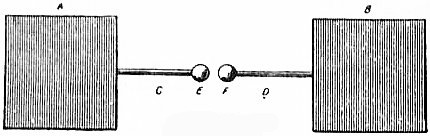
Fig. 1.
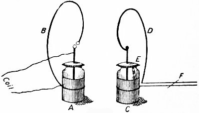
Fig. 2.
To produce the waves Hertz used two forms of vibrator. The first is represented in fig. 1. A and B are two zinc plates about 40 cm. square; to these brass rods, C, D, each about 30 cm. long, are soldered, terminating in brass balls E and F. To get good results it is necessary that these balls should be very brightly polished, and as they get roughened by the sparks which pass between them it is necessary to repolish them at short intervals; they should be shaded from light and from sparks, or other source of ultra-violet light. In order to excite the waves, C and D are connected to the two poles of an induction coil; sparks cross the air-gap which becomes a conductor, and the charges on the plates oscillate backwards and forwards like the charges on the coatings of a Leyden jar when it is short-circuited. The object of polishing the balls and screening off light is to get a sudden and sharp discharge; if the balls are rough there will be sharp points from which the charge will gradually leak, and the discharge will not be abrupt enough to start electrical vibrations, as these have an exceedingly short period. From the open form of this vibrator we should expect the radiation to be very large and the rate of decay of the amplitude very rapid. Bjerknes (Wied. Ann. 44, p. 74) found that the amplitude fell to 1/e of the original value, after a time 4T where T was the period of the electrical vibrations. Thus after a few vibrations the amplitude becomes inappreciable. To detect the waves produced by this vibrator Hertz used a piece of copper wire bent into a circle, the ends being furnished with two balls, or a ball and a point connected by a screw, so that the distance between them admitted of very fine adjustment. The radius of the circle for use with the vibrator just described was 35 cm., and was so chosen that the free period of the detector might be the same as that of the vibrator, and the effects in it increased by resonance. It is evident, however, that with a primary system as greatly damped as the vibrator used by Hertz, we could not expect very marked resonance effects, and as a matter of fact the accurate timing of vibrator and detector in this case is not very important. With electrical vibrators which can maintain a large number of vibrations, resonance effects are very striking, as is beautifully shown by the following experiment due to Lodge (Nature, 41, p. 368), whose researches have greatly advanced our knowledge of electric waves. A and C (fig. 2) are two Leyden jars, whose inner and outer coatings are connected by wires, B and D, bent so as to include a considerable area. There is an air-break in the circuit connecting the inside and outside of one of the jars, A, and electrical oscillations are started in A by joining the inside and outside with the terminals of a coil or electrical machine. The circuit in the jar C is provided with a sliding piece, F, by means of which the self-induction of the discharging circuit, and, therefore, the time of an electrical oscillation of the jar, can be adjusted. The inside and outside of this jar are put almost, but not quite, into electrical contact by means of a piece of tin-foil, E, bent over the lip of the jar. The jars are placed face to face so that the circuits B and D are parallel to each other, and approximately at right angles to the line joining their centres. When the electrical machine is in action sparks pass across the air-break in the circuit in A, and by moving the slider F it is possible to find one position for it in which sparks pass from the inside to the outside of C across the tin-foil, while when the slider is moved a short distance on either side of this position the sparks cease.
Hertz found that when he held his detector in the neighbourhood of the vibrator minute sparks passed between the balls. These sparks were not stopped when a large plate of non-conducting substance, such as the wall of a room, was interposed between the vibrator and detector, but a large plate of very thin metal stopped them completely.
To illustrate the analogy between electric waves and waves of light Hertz found another form of apparatus more convenient. The vibrator consisted of two equal brass cylinders, 12 cm. long and 3 cm. in diameter, placed with their axes coincident, and in the focal line of a large zinc parabolic mirror about 2 m. high, with a focal length of 12.5 cm. The ends of the cylinders nearest each other, between which the sparks passed, were carefully polished. The detector, which was placed in the focal line of an equal parabolic mirror, consisted of two lengths of wire, each having a straight piece about 50 cm. long and a curved piece about 15 cm. long bent round at right angles so as to pass through the back of the mirror. The ends which came through the mirror were connected with a spark micrometer, the sparks being observed from behind the mirror. The mirrors are shown, in fig. 3.
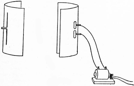
Fig. 3.
§ 2. Reflection and Refraction.—To show the reflection of the waves Hertz placed the mirrors side by side, so that their openings looked in the same direction, and their axes converged at a point about 3 m. from the mirrors. No sparks were then observed in the detector when the vibrator was in action. When, however, a large zinc plate about 2 m. square was placed at right angles to the line bisecting the angle between the axes of the mirrors sparks became visible, but disappeared again when the metal plate was twisted through an angle of about 15° to either side. This experiment showed that electric waves are reflected, and that, approximately at any rate, the angle of incidence is equal to the angle of reflection. To show refraction Hertz used a large prism made of hard pitch, about 1.5 m. high, with a slant side of 1.2 m. and an angle of 30°. When the waves from the vibrator passed through this the sparks in the detector were not excited when the axes of the two mirrors were parallel, but appeared when the axis of the mirror containing the detector made a certain angle with the axis of that containing the vibrator. When the system was adjusted for minimum deviation the sparks were most vigorous when the angle between the axes of the mirrors was 22°. This corresponds to an index of refraction of 1.69.
§ 3. Analogy to a Plate of Tourmaline.—If a screen be made by winding wire round a large rectangular framework, so that the turns of the wire are parallel to one pair of sides of the frame, and if this screen be interposed between the parabolic mirrors when placed so as to face each other, there will be no sparks in the detector when the turns of the wire are parallel to the focal lines of the mirror; but if the frame is turned through a right angle so that the wires are perpendicular to the focal lines of the mirror the sparks will recommence. If the framework is substituted for the metal plate in the experiment on the reflection of electric waves, sparks will appear in the detector when the wires are parallel to the focal lines of the mirrors, and will disappear when the wires are at right angles to these lines. Thus the framework reflects but does not transmit the waves when the electric force in them is parallel to the wires, while it transmits but does not reflect waves in which the electric force is at right angles to the wires. The wire framework behaves towards the electric waves exactly as a plate of tourmaline does to waves of light. Du Bois and Rubens (Wied. Ann. 49, p. 593), by using a framework wound with very fine wire placed very close together, have succeeded in polarizing waves of radiant heat, whose wave length, although longer than that of ordinary light, is very small compared with that of electric waves.
§ 4. Angle of Polarization.—When light polarized at right angles to the plane of incidence falls on a refracting substance at an angle tan−1μ, where μ is the refractive index of the substance, all the light is refracted and none reflected; whereas when light is polarized in the plane of incidence, some of the light is always reflected whatever the angle of incidence. Trouton (Nature, 39, p. 391) showed that similar effects take place with electric waves. From a paraffin wall 3 ft. thick, reflection always took place when the electric force in the incident wave was at right angles to the plane of incidence, whereas at a certain angle of incidence there was no reflection when the vibrator was turned, so that the electric force was in the plane of incidence. This shows that on the electromagnetic theory of light the electric force is at right angles to the plane of polarization.
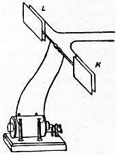
Fig. 4.
§ 5. Stationary Electrical Vibrations.—Hertz (Wied. Ann. 34, p. 609) made his experiments on these in a large room about 15 m. long. The vibrator, which was of the type first described, was placed at one end of the room, its plates being parallel to the wall, at the other end a piece of sheet zinc about 4 m. by 2 m. was placed vertically against the wall. The detector—the circular ring previously described—was held so that its plane was parallel to the metal plates of the vibrator, its centre on the line at right angles to the metal plate bisecting at right angles the spark gap of the vibrator, and with the spark gap of the detector parallel to that of the vibrator. The following effects were observed when the detector was moved about. When it was close up to the zinc plate there were no sparks, but they began to pass feebly as soon as it was moved forward a little way from the plate, and increased rapidly in brightness until it was about 1.8 m. from the plate, when they attained their maximum. When its distance was still further increased they diminished in brightness, and vanished again at a distance of about 4 m. from the plate. When the distance was still further increased they reappeared, attained another maximum, and so on. They thus exhibited a remarkable periodicity similar to that which occurs when stationary vibrations are produced by the interference of direct waves with those reflected from a surface placed at right angles to the direction of propagation. Similar periodic alterations in the spark were observed by Hertz when the waves, instead of passing freely through the air and being reflected by a metal plate at the end of the room, were led along wires, as in the arrangement shown in fig. 4. L and K are metal plates placed parallel to the plates of the vibrator, long parallel wires being attached to act as guides to the waves which were reflected from the isolated end. (Hertz used only one plate and one wire, but the double set of plates and wires introduced by Sarasin and De la Rive make the results more definite.) In this case the detector is best placed so that its plane is at right angles to the wires, while the air space is parallel to the plane containing the wires. The sparks instead of vanishing when the detector is at the far end of the wire are a maximum in this position, but wax and wane periodically as the detector is moved along the wires. The most obvious interpretation of these experiments was the one given by Hertz—that there was interference between the direct waves given out by the vibrator and those reflected either from the plate or from the ends of the wire, this interference giving rise to stationary waves. The places where the electric force was a maximum were the places where the sparks were brightest, and the places where the electric force was zero were the places where the sparks vanished. On this explanation the distance between two consecutive places where the sparks vanished would be half the wave length of the waves given out by the vibrator.
Some very interesting experiments made by Sarasin and De la Rive (Comptes rendus, 115, p. 489) showed that this explanation could not be the true one, since by using detectors of different sizes they found that the distance between two consecutive places where the sparks vanished depended mainly upon the size of the detector, and very little upon that of the vibrator. With small detectors they found the distance small, with large detectors, large; in fact it is directly proportional to the diameter of the detector. We can see that this result is a consequence of the large damping of the oscillations of the vibrator and the very small damping of those of the detector. Bjerknes showed that the time taken for the amplitude of the vibrations of the vibrator to sink to 1/e of their original value was only 4T, while for the detector it was 500T′, when T and T′ are respectively the times of vibration of the vibrator and the detector. The rapid decay of the oscillations of the vibrator will stifle the interference between the direct and the reflected wave, as the amplitude of the direct wave will, since it is emitted later, be much smaller than that of the reflected one, and not able to annul its effects completely; while the well-maintained vibrations of the detector will interfere and produce the effects observed by Sarasin and De la Rive. To see this let us consider the extreme case in which the oscillations of the vibrator are absolutely dead-beat. Here an impulse, starting from the vibrator on its way to the reflector, strikes against the detector and sets it in vibration; it then travels up to the plate and is reflected, the electric force in the impulse being reversed by reflection. After reflection the impulse again strikes the detector, which is still vibrating from the effects of the first impact; if the phase of this vibration is such that the reflected impulse tends to produce a current round the detector in the same direction as that which is circulating from the effects of the first impact, the sparks will be increased, but if the reflected impulse tends to produce a current in the opposite direction the sparks will be diminished. Since the electric force is reversed by reflection, the greatest increase in the sparks will take place when the impulse finds, on its return, the detector in the opposite phase to that in which it left it; that is, if the time which has elapsed between the departure and return of the impulse is equal to an odd multiple of half the time of vibration of the detector. If d is the distance of the detector from the reflector when the sparks are brightest, and V the velocity of propagation of electromagnetic disturbance, then 2d/V = (2n + 1) (T′/2); where n is an integer and T′ the time of vibration of the detector, the distance between two spark maxima will be VT′/2, and the places where the sparks are a minimum will be midway between the maxima. Sarasin and De la Rive found that when the same detector was used the distance between two spark maxima was the same with the waves through air reflected from a metal plate and with those guided by wires and reflected from the free ends of the wire, the inference being that the velocity of waves along wires is the same as that through the air. This result, which follows from Maxwell’s theory, when the wires are not too fine, had been questioned by Hertz on account of some of his experiments on wires.
§ 6. Detectors.—The use of a detector with a period of vibration of its own thus tends to make the experiments more complicated, and many other forms of detector have been employed by subsequent experimenters. For example, in place of the sparks in air the luminous discharge through a rarefied gas has been used by Dragoumis, Lecher (who used tubes without electrodes laid across the wires in an arrangement resembling that shown in fig. 7) and Arons. A tube containing neon at a low pressure is especially suitable for this purpose. Zehnder (Wied. Ann. 47, p. 777) used an exhausted tube to which an external electromotive force almost but not quite sufficient of itself to produce a discharge was applied; here the additional electromotive force due to the waves was sufficient to start the discharge. Detectors depending on the heat produced by the rapidly alternating currents have been used by Paalzow and Rubens, Rubens and Ritter, and I. Klemenčič. Rubens measured the heat produced by a bolometer arrangement, and Klemenčič used a thermo-electric method for the same purpose; in consequence of the great increase in the sensitiveness of galvanometers these methods are now very frequently resorted to. Boltzmann used an electroscope as a detector. The spark gap consisted of a ball and a point, the ball being connected with the electroscope and the point with a battery of 200 dry cells. When the spark passed the cells charged up the electroscope. Ritter utilized the contraction of a frog’s leg as a detector, Lucas and Garrett the explosion produced by the sparks in an explosive mixture of hydrogen and oxygen; while Bjerknes and Franke used the mechanical attraction between oppositely charged conductors. If the two sides of the spark gap are connected with the two pairs of quadrants of a very delicate electrometer, the needle of which is connected with one pair of quadrants, there will be a deflection of the electrometer when the detector is struck by electric waves. A very efficient detector is that invented by E. Rutherford (Trans. Roy. Soc. A. 1897, 189, p. 1); it consists of a bundle of fine iron wires magnetized to saturation and placed inside a small magnetizing coil, through which the electric waves cause rapidly alternating currents to pass which demagnetize the soft iron. If the instrument is used to detect waves in air, long straight wires are attached to the ends of the demagnetizing coil to collect the energy from the field; to investigate waves in wires it is sufficient to make a loop or two in the wire and place the magnetized piece of iron inside it. The amount of demagnetization which can be observed by the change in the deflection of a magnetometer placed near the iron, measures the intensity of the electric waves, and very accurate determinations can be made with ease with this apparatus. It is also very delicate, though in this respect it does not equal the detector to be next described, the coherer; Rutherford got indications in 1895 when the vibrator was ¾ of a mile away from the detector, and where the waves had to traverse a thickly populated part of Cambridge. It can also be used to measure the coefficient of damping of the electric waves, for since the wire is initially magnetized to saturation, if the direction of the current when it first begins to flow in the magnetizing coil is such as to tend to increase the magnetization of the wire, it will produce no effect, and it will not be until the current is reversed that the wire will lose some of its magnetization. The effect then gives the measure of the intensity half a period after the commencement of the waves. If the wire is put in the coil the opposite way, i.e. so that the magnetic force due to the current begins at once to demagnetize the wire, the demagnetization gives a measure of the initial intensity of the waves. Comparing this result with that obtained when the wires were reversed, we get the coefficient of damping. A very convenient detector of electric waves is the one discovered almost simultaneously by Fessenden (Electrotech. Zeits., 1903, 24, p. 586) and Schlömilch (ibid. p. 959). This consists of an electrolytic cell in which one of the electrodes is an exceedingly fine point. The electromotive force in the circuit is small, and there is large polarization in the circuit with only a small current. When the circuit is struck by electric waves there is an increase in the currents due to the depolarization of the circuit. If a galvanometer is in the circuit, the increased deflection of the instrument will indicate the presence of the waves.
§ 7. Coherers.—The most sensitive detector of electric waves is the “coherer,” although for metrical work it is not so suitable as that just described. It depends upon the fact discovered by Branly (Comptes rendus, 111, p. 785; 112, p. 90) that the resistance between loose metallic contacts, such as a pile of iron turnings, diminishes when they are struck by an electric wave. One of the forms made by Lodge (The Work of Hertz and some of his Successors, 1894) on this principle consists simply of a glass tube containing iron turnings, in contact with which are wires led into opposite ends of the tube. The arrangement is placed in series with a galvanometer (one of the simplest kind will do) and a battery; when the iron turnings are struck by electric waves their resistance is diminished and the deflection of the galvanometer is increased. Thus the deflection of the galvanometer can be used to indicate the arrival of electric waves. The tube must be tapped between each experiment, and the deflection of the galvanometer brought back to about its original value. This detector is marvellously delicate, but not metrical, the change produced in the resistance depending upon so many things besides the intensity of the waves that the magnitude of the galvanometer deflection is to some extent a matter of chance. Instead of the iron turnings we may use two iron wires, one resting on the other; the resistance of this contact will be altered by the incidence of the waves. To get greater regularity Bose uses, instead of the iron turnings, spiral springs, which are pushed against each other by means of a screw until the most sensitive state is attained. The sensitiveness of the coherer depends on the electromotive force put in the galvanometer circuit. Very sensitive ones can be made by using springs of very fine silver wire coated electrolytically with nickel. Though the impact of electric waves generally produces a diminution of resistance with these loose contacts, yet there are exceptions to the rule. Thus Branly showed that with lead peroxide, PbO2, there is an increase in resistance. Aschkinass proved the same to be true with copper sulphide, CuS; and Bose showed that with potassium there is an increase of resistance and great power of self-recovery of the original resistance after the waves have ceased. Several theories of this action have been proposed. Branly (Lumière électrique, 40, p. 511) thought that the small sparks which certainly pass between adjacent portions of metal clear away layers of oxide or some other kind of non-conducting film, and in this way improve the contact. It would seem that if this theory is true the films must be of a much more refined kind than layers of oxide or dirt, for the coherer effect has been observed with clean non-oxidizable metals. Lodge explains the effect by supposing that the heat produced by the sparks fuses adjacent portions of metal into contact and hence diminishes the resistance; it is from this view of the action that the name coherer is applied to the detector. Auerbeck thought that the effect was a mechanical one due to the electrostatic attractions between the various small pieces of metal. It is probable that some or all of these causes are at work in some cases, but the effects of potassium make us hesitate to accept any of them as the complete explanation. Blanc (Ann. chim. phys., 1905, [8] 6, p. 5), as the result of a long series of experiments, came to the conclusion that coherence is due to pressure. He regarded the outer layers as different from the mass of the metal and having a much greater specific resistance. He supposed that when two pieces of metal are pressed together the molecules diffuse across the surface, modifying the surface layers and increasing their conductivity.
§ 8. Generators of Electric Waves.—Bose (Phil. Mag. 43, p. 55) designed an instrument which generates electric waves with a length of not more than a centimetre or so, and therefore allows their properties to be demonstrated with apparatus of moderate dimensions. The waves are excited by sparking between two platinum beads carried by jointed electrodes; a platinum sphere is placed between the beads, and the distance between the beads and the sphere can be adjusted by bending the electrodes. The diameter of the sphere is 8 mm., and the wave length of the shortest electrical waves generated is said to be about 6 mm. The beads are connected with the terminals of a small induction coil, which, with the battery to work it and the sparking arrangement, are enclosed in a metal box, the radiation passing out through a metal tube opposite to the spark gap. The ordinary vibrating break of the coil is not used, a single spark made by making and breaking the circuit by means of a button outside the box being employed instead. The detector is one of the spiral spring coherers previously described; it is shielded from external disturbance by being enclosed in a metal box provided with a funnel-shaped opening to admit the radiation. The wires leading from the coherers to the galvanometer are also surrounded by metal tubes to protect them from stray radiation. The radiating apparatus and the receiver are mounted on stands sliding in an optical bench. If a parallel beam of radiation is required, a cylindrical lens of ebonite or sulphur is mounted in a tube fitting on to the radiator tube and stopped by a guide when the spark is at the principal focal line of the lens. For experiments requiring angular measurements a spectrometer circle is mounted on one of the sliding stands, the receiver being carried on a radial arm and pointing to the centre of the circle. The arrangement is represented in fig. 5.
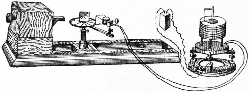
Fig. 5.
With this apparatus the laws of reflection, refraction and polarization can readily be verified, and also the double refraction of crystals, and of bodies possessing a fibrous or laminated structure such as jute or books. (The double refraction of electric waves seems first to have been observed by Righi, and other researches on this subject have been made by Garbasso and Mack.) Bose showed the rotation of the plane of polarization by means of pieces of twisted jute rope; if the pieces were arranged so that their twists were all in one direction and placed in the path of the radiation, they rotated the plane of polarization in a direction depending upon the direction of twist; if they were mixed so that there were as many twisted in one direction as the other, there was no rotation.
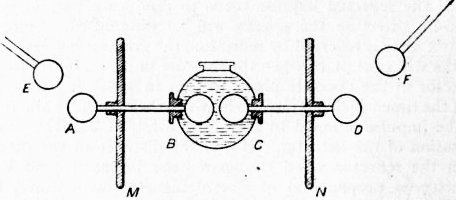
Fig. 6.
A series of experiments showing the complete analogy between electric and light waves is described by Righi in his book L’Ottica delle oscillazioni elettriche. Righi’s exciter, which is especially convenient when large statical electric machines are used instead of induction coils, is shown in fig. 6. E and F are balls connected with the terminals of the machine, and AB and CD are conductors insulated from each other, the ends B, C, between which the sparks pass, being immersed in vaseline oil. The period of the vibrations given out by the system is adjusted by means of metal plates M and N attached to AB and CD. When the waves are produced by induction coils or by electrical machines the intervals between the emission of different sets of waves occupy by far the largest part of the time. Simon (Wied. Ann., 1898, 64, p. 293; Phys. Zeit., 1901, 2, p. 253), Duddell (Electrician, 1900, 46, p. 269) and Poulsen (Electrotech. Zeits., 1906, 27, p. 1070) reduced these intervals very considerably by using the electric arc to excite the waves, and in this way produced electrical waves possessing great energy. In these methods the terminals between which the arc is passing are connected through coils with self-induction L to the plates of a condenser of capacity C. The arc is not steady, but is continually varying. This is especially the case when it passes through hydrogen. These variations excite vibrations with a period 2π√(LC) in the circuit containing the capacity of the self-induction. By this method Duddell produced waves with a frequency of 40,000. Poulsen, who cooled the terminals of the arc, produced waves with a frequency of 1,000,000, while Stechodro (Ann. der Phys. 27, p. 225) claims to have produced waves with three hundred times this frequency, i.e. having a wave length of about a metre. When the self-induction and capacity are large so that the frequency comes within the limits of the frequency of audible notes, the system gives out a musical note, and the arrangement is often referred to as the singing arc.
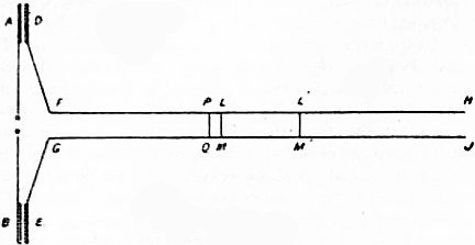
Fig. 7.
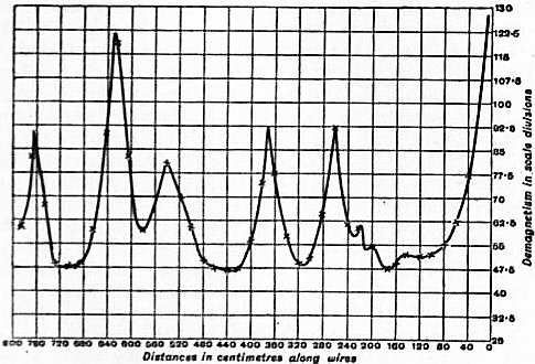
Fig. 8.
§ 9. Waves in Wires.—Many problems on electric waves along wires can readily be investigated by a method due to Lecher (Wied. Ann. 41, p. 850), and known as Lecher’s bridge, which furnishes us with a means of dealing with waves of a definite and determinable wave-length. In this arrangement (fig. 7) two large plates A and B are, as in Hertz’s exciter, connected with the terminals of an induction coil; opposite these and insulated from them are two smaller plates D, E, to which long parallel wires DFH, EGJ are attached. These wires are bridged across by a wire LM, and their farther ends H, J, may be insulated, or connected together, or with the plates of a condenser. To detect the waves in the circuit beyond the bridge, Lecher used an exhausted tube placed across the wires, and Rubens a bolometer, but Rutherford’s detector is the most convenient and accurate. If this detector is placed in a fixed position at the end of the circuit, it is found that the deflections of this detector depend greatly upon the position of the bridge LM, rising rapidly to a maximum for some positions, and falling rapidly away when the bridge is displaced. As the bridge is moved from the coil end towards the detector the deflections show periodic variations, such as are represented in fig. 8 when the ordinates represent the deflections of the detector and the abscissae the distance of the bridge from the ends D, E. The maximum deflections of the detector correspond to the positions in which the two circuits DFLMGE, HLMJ (in which the vibrations are but slightly damped) are in resonance. For since the self-induction and resistance of the bridge LM is very small compared with that of the circuit beyond, it follows from the theory of circuits in parallel that only a small part of the current will in general flow round the longer circuit; it is only when the two circuits DFLMGE, HLMJ are in resonance that a considerable current will flow round the latter. Hence when we get a maximum effect in the detector we know that the waves we are dealing with are those corresponding to the free periods of the system HLMJ, so that if we know the free periods of this circuit we know the wave length of the electric waves under consideration. Thus if the ends of the wires H, J are free and have no capacity, the current along them must vanish at H and J, which must be in opposite electric condition. Hence half the wave length must be an odd submultiple of the length of the circuit HLMJ. If H and J are connected together the wave length must be a submultiple of the length of this circuit. When the capacity at the ends is appreciable the wave length of the circuit is determined by a somewhat complex expression. To facilitate the determination of the wave length in such cases, Lecher introduced a second bridge L′M′, and moved this about until the deflection of the detector was a maximum; when this occurs the wave length is one of those corresponding to the closed circuit LMM′L′, and must therefore be a submultiple of the length of the circuit. Lecher showed that if instead of using a single wire LM to form the bridge, he used two parallel wires PQ, LM, placed close together, the currents in the further circuit were hardly appreciably diminished when the main wires were cut between PL and QM. Blondlot used a modification of this apparatus better suited for the production of short waves. In his form (fig. 9) the exciter consists of two semicircular arms connected with the terminals of an induction coil, and the long wires, instead of being connected with the small plates, form a circuit round the exciter.
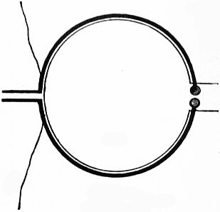
Fig. 9.
As an example of the use of Lecher’s arrangement, we may quote Drude’s application of the method to find the specific induction capacity of dielectrics under electric oscillations of varying frequency. In this application the ends of the wire are connected to the plates of a condenser, the space between whose plates can be filled with the liquid whose specific inductive capacity is required, and the bridge is moved until the detector at the end of the circuit gives the maximum deflection. Then if λ is the wave length of the waves, λ is the wave length of one of the free vibrations of the system HLMJ; hence if C is the capacity of the condenser at the end in electrostatic measure we have
cot 2πl
λ = C
2πl C′l
λ
where l is the distance of the condenser from the bridge and C′ is the capacity of unit length of the wire. In the condenser part of the lines of force will pass through air and part through the dielectric; hence C will be of the form C0 + KC1 where K is the specific inductive capacity of the dielectric. Hence if l is the distance of maximum deflection when the dielectric is replaced by air, l′ when filled with a dielectric whose specific inductive capacity is known to be K′, and l″ the distance when filled with the dielectric whose specific inductive capacity is required, we easily see that—
cot 2πl − cot 2πl′
λ λ = 1 − K′
cot 2πl − cot 2πl″ 1 − K
λ λ
an equation by means of which K can be determined. It was in this way that Drude investigated the specific inductive capacity with varying frequency, and found a falling off in the specific inductive capacity with increase of frequency when the dielectrics contained the radicle OH. In another method used by him the wires were led through long tanks filled with the liquid whose specific inductive capacity was required; the velocity of propagation of the electric waves along the wires in the tank being the same as the velocity of propagation of an electromagnetic disturbance through the liquid filling the tank, if we find the wave length of the waves along the wires in the tank, due to a vibration of a given frequency, and compare this with the wave lengths corresponding to the same frequency when the wires are surrounded by air, we obtain the velocity of propagation of electromagnetic disturbance through the fluid, and hence the specific inductive capacity of the fluid.
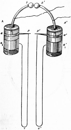
Fig. 10.
§ 10. Velocity of Propagation of Electromagnetic Effects through Air.—The experiments of Sarasin and De la Rive already described (see § 5) have shown that, as theory requires, the velocity of propagation of electric effects through air is the same as along wires. The same result had been arrived at by J.J. Thomson, although from the method he used greater differences between the velocities might have escaped detection than was possible by Sarasin and De la Rive’s method. The velocity of waves along wires has been directly determined by Blondlot by two different methods. In the first the detector consisted of two parallel plates about 6 cm. in diameter placed a fraction of a millimetre apart, and forming a condenser whose capacity C was determined in electromagnetic measure by Maxwell’s method. The plates were connected by a rectangular circuit whose self-induction L was calculated from the dimensions of the rectangle and the size of the wire. The time of vibration T is equal to 2π√(LC). (The wave length corresponding to this time is long compared with the length of the circuit, so that the use of this formula is legitimate.) This detector is placed between two parallel wires, and the waves produced by the exciter are reflected from a movable bridge. When this bridge is placed just beyond the detector vigorous sparks are observed, but as the bridge is pushed away a place is reached where the sparks disappear; this place is distance 2/λ from the detector, when λ is the wave length of the vibration given out by the detector. The sparks again disappear when the distance of the bridge from the detector is 3λ/4. Thus by measuring the distance between two consecutive positions of the bridge at which the sparks disappear λ can be determined, and v, the velocity of propagation, is equal to λ/T. As the means of a number of experiments Blondlot found v to be 3.02 × 1010 cm./sec., which, within the errors of experiment, is equal to 3 × 1010 cm./sec., the velocity of light. A second method used by Blondlot, and one which does not involve the calculation of the period, is as follows:—A and A′ (fig. 10) are two equal Leyden jars coated inside and outside with tin-foil. The outer coatings form two separate rings a, a1; a′, a′1, and the inner coatings are connected with the poles of the induction coil by means of the metal pieces b, b′. The sharply pointed conductors p and p′, the points of which are about ½ mm. apart, are connected with the rings of the tin-foil a and a′, and two long copper wires pca1, p′c′a′1, 1029 cm. long, connect these points with the other rings a1, a1′. The rings aa′, a1a1′, are connected by wet strings so as to charge up the jars. When a spark passes between b and b′, a spark at once passes between pp′, and this is followed by another spark when the waves travelling by the paths a1cp, a′1c′p′ reach p and p′. The time between the passage of these sparks, which is the time taken by the waves to travel 1029 cm., was observed by means of a rotating mirror, and the velocity measured in 15 experiments varied between 2.92 × 10¹⁰ and 3.03 × 1010 cm./sec., thus agreeing well with that deduced by the preceding method. Other determinations of the velocity of electromagnetic propagation have been made by Lodge and Glazebrook, and by Saunders.
On Maxwell’s electromagnetic theory the velocity of propagation of electromagnetic disturbances should equal the velocity of light, and also the ratio of the electromagnetic unit of electricity to the electrostatic unit. A large number of determinations of this ratio have been made:—
Observer. Date. Ratio 1010 ×.
Klemenčič 1884 3.019 cm./sec.
Himstedt 1888 3.009 cm./sec.
Rowland 1889 2.9815 cm./sec.
Rosa 1889 2.9993 cm./sec.
J.J. Thomson and Searle 1890 2.9955 cm./sec.
Webster 1891 2.987 cm./sec.
Pellat 1891 3.009 cm./sec.
Abraham 1892 2.992 cm./sec.
Hurmuzescu 1895 3.002 cm./sec.
Rosa 1908 2.9963 cm./sec.
The mean of these determinations is 3.001 × 1010 cm./sec., while the mean of the last five determinations of the velocity of light in air is given by Himstedt as 3.002 × 1010 cm./sec. From these experiments we conclude that the velocity of propagation of an electromagnetic disturbance is equal to the velocity of light, and to the velocity required by Maxwell’s theory.
In experimenting with electromagnetic waves it is in general more difficult to measure the period of the oscillations than their wave length. Rutherford used a method by which the period of the vibration can easily be determined; it is based upon the theory of the distribution of alternating currents in two circuits ACB, ADB in parallel. If A and B are respectively the maximum currents in the circuits ACB, ADB, then
A = √ S² + (N − M)²p²
B R² + (L − M)²p²
when R and S are the resistances, L and N the coefficients of self-induction of the circuits ACB, ADB respectively, M the coefficient of mutual induction between the circuits, and p the frequency of the currents. Rutherford detectors were placed in the two circuits, and the circuits adjusted until they showed that A = B; when this is the case
p² = R² − S² .
N² − L² − 2M (N − L)
If we make one of the circuits, ADB, consist of a short length of a high liquid resistance, so that S is large and N small, and the other circuit ACB of a low metallic resistance bent to have considerable self-induction, the preceding equation becomes approximately p = S/L, so that when S and L are known p is readily determined.
(J. J. T.)
ELECTROCHEMISTRY. The present article deals with processes that involve the electrolysis of aqueous solutions, whilst those in which electricity is used in the manufacture of chemical products at furnace temperatures are treated under Electrometallurgy, although, strictly speaking, in some cases (e.g. calcium carbide and phosphorus manufacture) they are not truly metallurgical in character. For the theory and elemental laws of electro-deposition see Electrolysis; and for the construction and use of electric generators see Dynamo and Battery: Electric. The importance of the subject may be gauged by the fact that all the aluminium, magnesium, sodium, potassium, calcium carbide, carborundum and artificial graphite, now placed on the market, is made by electrical processes, and that the use of such processes for the refining of copper and silver, and in the manufacture of phosphorus, potassium chlorate and bleach, already pressing very heavily on the older non-electrical systems, is every year extending. The convenience also with which the energy of waterfalls can be converted into electric energy has led to the introduction of chemical industries into countries and districts where, owing to the absence of coal, they were previously unknown. Norway and Switzerland have become important producers of chemicals, and pastoral districts such as those in which Niagara or Foyers are situated manufacturing centres. In this way the development of the electrochemical industry is in a marked degree altering the distribution of trade throughout the world.
Electrolytic Refining of Metals.—The principle usually followed in the electrolytic refining of metals is to cast the impure metal into plates, which are exposed as anodes in a suitable solvent, commonly a salt of the metal under treatment. On passing a current of electricity, of which the volume and pressure are adjusted to the conditions of the electrolyte and electrodes, the anode slowly dissolves, leaving the insoluble impurities in the form of a sponge, if the proportion be considerable, but otherwise as a mud or slime which becomes detached from the anode surface and must be prevented from coming into contact with the cathode. The metal to be refined passing into solution is concurrently deposited at the cathode. Soluble impurities which are more electro-negative than the metal under treatment must, if present, be removed by a preliminary process, and the voltage and other conditions must be so selected that none of the more electro-positive metals are co-deposited with the metal to be refined. From these and other considerations it is obvious that (1) the electrolyte must be such as will freely dissolve the metal to be refined; (2) the electrolyte must be able to dissolve the major portion of the anode, otherwise the mass of insoluble matter on the outer layer will prevent access of electrolyte to the core, which will thus escape refining; (3) the electrolyte should, if possible, be incapable of dissolving metals more electro-negative than that to be refined; (4) the proportion of soluble electro-positive impurities must not be excessive, or these substances will accumulate too rapidly in the solution and necessitate its frequent purification; (5) the current density must be so adjusted to the strength of the solution and to other conditions that no relatively electro-positive metal is deposited, and that the cathode deposit is physically suitable for subsequent treatment; (6) the current density should be as high as is consistent with the production of a pure and sound deposit, without undue expense of voltage, so that the operation may be rapid and the “turnover” large; (7) the electrolyte should be as good a conductor of electricity as possible, and should not, ordinarily, be altered chemically by exposure to air; and (8) the use of porous partitions should be avoided, as they increase the resistance and usually require frequent renewal. For details of the practical methods see Gold; Silver; Copper and headings for other metals.
Electrolytic Manufacture of Chemical Products.—When an aqueous solution of the salt of an alkali metal is electrolysed, the metal reacts with the water, as is well known, forming caustic alkali, which dissolves in the solution, and hydrogen, which comes off as a gas. So early as 1851 a patent was taken out by Cooke for the production of caustic alkali without the use of a separate current, by immersing iron and copper plates on opposite sides of a porous (biscuit-ware) partition in a suitable cell, containing a solution of the salt to be electrolysed, at 21°-65° C. (70°-150° F.). The solution of the iron anode was intended to afford the necessary energy. In the same year another patent was granted to C. Watt for a similar process, involving the employment of an externally generated current. When an alkaline chloride, say sodium chloride, is electrolysed with one electrode immersed in a porous cell, while caustic soda is formed at the cathode, chlorine is deposited at the anode. If the latter be insoluble, the gas diffuses into the solution and, when this becomes saturated, escapes into the air. If, however, no porous division be used to prevent the intermingling by diffusion of the anode and cathode solutions, a complicated set of subsidiary reactions takes place. The chlorine reacts with the caustic soda, forming sodium hypochlorite, and this in turn, with an excess of chlorine and at higher temperatures, becomes for the most part converted into chlorate, whilst any simultaneous electrolysis of a hydroxide or water and a chloride (so that hydroxyl and chlorine are simultaneously liberated at the anode) also produces oxygen-chlorine compounds direct. At the same time, the diffusion of these compounds into contact with the cathode leads to a partial reduction to chloride, by the removal of combined oxygen by the instrumentality of the hydrogen there evolved. In proportion as the original chloride is thus reproduced, the efficiency of the process is of course diminished. It is obvious that, with suitable methods and apparatus, the electrolysis of alkaline chlorides may be made to yield chlorine, hypochlorites (bleaching liquors), chlorates or caustic alkali, but that great care must be exercised if any of these products is to be obtained pure and with economy. Many patents have been taken out in this branch of electrochemistry, but it is to be remarked that that granted to C. Watt traversed the whole of the ground. In his process a current was passed through a tank divided into two or three cells by porous partitions, hoods and tubes were arranged to carry off chlorine and hydrogen respectively, and the whole was heated to 120° F. by a steam jacket when caustic alkali was being made. Hypochlorites were made, at ordinary temperatures, and chlorates at higher temperatures, in a cell without a partition in which the cathode was placed horizontally immediately above the anode, to favour the mixing of the ascending chlorine with the descending caustic solution.
The relation between the composition of the electrolyte and the various conditions of current-density, temperature and the like has been studied by F. Oettel (Zeitschrift f. Elektrochem., 1894, vol. i. pp. 354 and 474) in connexion with the production of hypochlorites and chlorates in tanks without diaphragms, by C. Häussermann and W. Naschold (Chemiker Zeitung, 1894, vol. xviii. p. 857) for their production in cells with porous diaphragms, and by F. Haber and S. Grinberg (Zeitschrift f. anorgan. Chem., 1898, vol. xvi. pp. 198, 329, 438) in connexion with the electrolysis of hydrochloric acid. Oettel, using a 20% solution of potassium chloride, obtained the best yield of hypochlorite with a high current-density, but as soon as 1¼% of bleaching chlorine (as hypochlorite) was present, the formation of chlorate commenced. The yield was at best very low as compared with that theoretically possible. The best yield of chlorate was obtained when from 1 to 4% of caustic potash was present. With high current-density, heating the solution tended to increase the proportion of chlorate to hypochlorite, but as the proportion of water decomposed is then higher, the amount of chlorine produced must be less and the total chlorine efficiency lower. He also traced a connexion between alkalinity, temperature and current-density, and showed that these conditions should be mutually adjusted. With a current-density of 130 to 140 amperes per sq. ft., at 3 volts, passing between platinum electrodes, he attained to a current-efficiency of 52%, and each (British) electrical horse-power hour was equivalent to a production of 1378.5 grains of potassium chlorate. In other words, each pound of chlorate would require an expenditure of nearly 5.1 e.h.p. hours. One of the earliest of the more modern processes was that of E. Hermite, which consisted in the production of bleach-liquors by the electrolysis (according to the 1st edition of the 1884 patent) of magnesium or calcium chloride between platinum anodes carried in wooden frames, and zinc cathodes. The solution, containing hypochlorites and chlorates, was then applied to the bleaching of linen, paper-pulp or the like, the solution being used over and over again. Many modifications have been patented by Hermite, that of 1895 specifying the use of platinum gauze anodes, held in ebonite or other frames. Rotating zinc cathodes were used, with scrapers to prevent the accumulation of a layer of insoluble magnesium compounds, which would otherwise increase the electrical resistance beyond reasonable limits. The same inventor has patented the application of electrolysed chlorides to the purification of starch by the oxidation of less stable organic bodies, to the bleaching of oils, and to the purification of coal gas, spirit and other substances. His system for the disinfection of sewage and similar matter by the electrolysis of chlorides, or of sea-water, has been tried, but for the most part abandoned on the score of expense. Reference may be made to papers written in the early days of the process by C.F. Cross and E.J. Bevan (Journ. Soc. Chem. Industry, 1887, vol. vi. p. 170, and 1888, vol. vii. p. 292), and to later papers by P. Schoop (Zeitschrift f. Elektrochem., 1895, vol. ii. pp. 68, 88, 107, 209, 289).
E. Kellner, who in 1886 patented the use of cathode (caustic soda) and anode (chlorine) liquors in the manufacture of cellulose from wood-fibre, and has since evolved many similar processes, has produced an apparatus that has been largely used. It consists of a stoneware tank with a thin sheet of platinum-iridium alloy at either end forming the primary electrodes, and between them a number of glass plates reaching nearly to the bottom, each having a platinum gauze sheet on either side; the two sheets belonging to each plate are in metallic connexion, but insulated from all the others, and form intermediary or bi-polar electrodes. A 10-12% solution of sodium chloride is caused to flow upwards through the apparatus and to overflow into troughs, by which it is conveyed (if necessary through a cooling apparatus) back to the circulating pump. Such a plant has been reported as giving 0.229 gallon of a liquor containing 1% of available chlorine per kilowatt hour, or 0.171 gallon per e.h.p. hour. Kellner has also patented a “bleaching-block,” as he terms it, consisting of a frame carrying parallel plates similar in principle to those last described. The block is immersed in the solution to be bleached, and may be lifted in or out as required. O. Knöfler and Gebauer have also a system of bi-polar electrodes, mounted in a frame in appearance resembling a filter-press.
Other Electrochemical Processes.—It is obvious that electrolytic iodine and bromine, and oxygen compounds of these elements, may be produced by methods similar to those applied to chlorides (see Alkali Manufacture and Chlorates), and Kellner and others have patented processes with this end in view. Hydrogen and oxygen may also be produced electrolytically as gases, and their respective reducing and oxidizing powers at the moment of deposition on the electrode are frequently used in the laboratory, and to some extent industrially, chiefly in the field of organic chemistry. Similarly, the formation of organic halogen products may be effected by electrolytic chlorine, as, for example, in the production of chloral by the gradual introduction of alcohol into an anode cell in which the electrolyte is a strong solution of potassium chloride. Again, anode reactions, such as are observed in the electrolysis of the fatty acids, may be utilized, as, for example, when the radical CH3CO2—deposited at the anode in the electrolysis of acetic acid—is dissociated, two of the groups react to give one molecule of ethane, C2H6, and two of carbon dioxide. This, which has long been recognized as a class-reaction, is obviously capable of endless variation. Many electrolytic methods have been proposed for the purification of sugar; in some of them soluble anodes are used for a few minutes in weak alkaline solutions, so that the caustic alkali from the cathode reaction may precipitate chemically the hydroxide of the anode metal dissolved in the liquid, the precipitate carrying with it mechanically some of the impurities present, and thus clarifying the solution. In others the current is applied for a longer time to the original sugar-solution with insoluble (e.g. carbon) anodes. F. Peters has found that with these methods the best results are obtained when ozone is employed in addition to electrolytic oxygen. Use has been made of electrolysis in tanning operations, the current being passed through the tan-liquors containing the hides. The current, by endosmosis, favours the passage of the solution into the hide-substance, and at the same time appears to assist the chemical combinations there occurring; hence a great reduction in the time required for the completion of the process. Many patents have been taken out in this direction, one of the best known being that of Groth, experimented upon by S. Rideal and A.P. Trotter (Journ. Soc. Chem. Indust., 1891, vol. x. p. 425), who employed copper anodes, 4 sq. ft. in area, with current-densities of 0.375 to 1 (ranging in some cases to 7.5) ampere per sq. ft., the best results being obtained with the smaller current-densities. Electrochemical processes are often indirectly used, as for example in the Villon process (Elec. Rev., New York, 1899, vol. xxxv. p. 375) applied in Russia to the manufacture of alcohol, by a series of chemical reactions starting from the production of acetylene by the action of water upon calcium carbide. The production of ozone in small quantities during electrolysis, and by the so-called silent discharge, has long been known, and the Siemens induction tube has been developed for use industrially. The Siemens and Halske ozonizer, in form somewhat resembling the old laboratory instrument, is largely used in Germany; working with an alternating current transformed up to 6500 volts, it has been found to give 280 grains or more of ozone per e.h.p. hour. E. Andreoli (whose first British ozone patent was No. 17,426 of 1891) uses flat aluminium plates and points, and working with an alternating current of 3000 volts is said to have obtained 1440 grains per e.h.p. hour. Yarnold’s process, using corrugated glass plates coated on one side with gold or other metal leaf, is stated to have yielded as much as 2700 grains per e.h.p. hour. The ozone so prepared has numerous uses, as, for example, in bleaching oils, waxes, fabrics, &c., sterilizing drinking-water, maturing wines, cleansing foul beer-casks, oxidizing oil, and in the manufacture of vanillin.
For further information the following books, among others, may be consulted:—Haber, Grundriss der technischen Elektrochemie (München, 1898); Borchers and M’Millan, Electric Smelting and Refining (London, 1904); E.D. Peters, Principles of Copper Smelting (New York, 1907); F. Peters, Angewandte Elektrochemie, vols. ii. and iii. (Leipzig, 1900); Gore, The Art of Electrolytic Separation of Metals (London, 1890); Blount, Practical Electro-Chemistry (London, 1906); G. Langbein, Vollständiges Handbuch der galvanischen Metall-Niederschläge (Leipzig, 1903), Eng. trans. by W.T. Brannt (1909); A. Watt, Electro-Plating and Electro-Refining of Metals (London, 1902); W.H. Wahl, Practical Guide to the Gold and Silver Electroplater, &c. (Philadelphia, 1883); Wilson, Stereotyping and Electrotyping (London); Lunge, Sulphuric Acid and Alkali, vol. iii. (London, 1909). Also papers in various technical periodicals. The industrial aspect is treated in a Gartside Report, Some Electro-Chemical Centres (Manchester, 1908), by J.N. Pring.
(W. G. M.)
ELECTROCUTION (an anomalous derivative from “electro-execution”; syn. “electrothanasia”), the popular name, invented in America, for the infliction of the death penalty on criminals (see Capital Punishment) by passing through the body of the condemned a sufficient current of electricity to cause death. The method was first adopted by the state of New York, a law making this method obligatory having been passed and approved by the governor on the 4th of June 1888. The law provides that there shall be present, in addition to the warden, two physicians, twelve reputable citizens of full age, seven deputy sheriffs, and such ministers, priests or clergymen, not exceeding two, as the criminal may request. A post-mortem examination of the body of the convict is required, and the body, unless claimed by relatives, is interred in the prison cemetery with a sufficient quantity of quicklime to consume it. The law became effective in New York on the 1st of January 1889. The first criminal to be executed by electricity was William Kemmler, on the 6th of August 1890, at Auburn prison. The validity of the New York law had previously been attacked in regard to this case (Re Kemmler, 1889; 136 U.S. 436), as providing “a cruel and unusual punishment” and therefore being contrary to the Constitution; but it was sustained in the state courts and finally in the Federal courts. By 1906 about one hundred and fifteen murderers had been successfully executed by electricity in New York state in Sing Sing, Auburn and Dannemora prisons. The method has also been adopted by the states of Ohio (1896), Massachusetts (1898), New Jersey (1906), Virginia (1908) and North Carolina (1910).
The apparatus consists of a stationary engine, an alternating dynamo capable of generating a current at a pressure of 2000 volts, a “death-chair” with adjustable head-rest, binding straps and adjustable electrodes devised by E.F. Davis, the state electrician of New York. The voltmeter, ammeter and switch-board controlling the current are located in the execution-room; the dynamo-room is communicated with by electric signals. Before each execution the entire apparatus is thoroughly tested. When everything is in readiness the criminal is brought in and seats himself in the death-chair. His head, chest, arms and legs are secured by broad straps; one electrode thoroughly moistened with salt-solution is affixed to the head, and another to the calf of one leg, both electrodes being moulded so as to secure good contact. The application of the current is usually as follows: the contact is made with a high voltage (1700-1800 volts) for 5 to 7 seconds, reduced to 200 volts until a half-minute has elapsed; raised to high voltage for 3 to 5 seconds, again reduced to low voltage for 3 to 5 seconds, again reduced to a low voltage until one minute has elapsed, when it is again raised to the high voltage for a few seconds and the contact broken. The ammeter usually shows that from 7 to 10 amperes pass through the criminal’s body. A second or even a third brief contact is sometimes made, partly as a precautionary measure, but rather the more completely to abolish reflexes in the dead body. Calculations have shown that by this method of execution from 7 to 10 h. p. of energy are liberated in the criminal’s body. The time consumed by the strapping-in process is usually about 45 seconds, and the first contact is made about 70 seconds after the criminal has entered the death-chamber.
When properly performed the effect is painless and instantaneous death. The mechanism of life, circulation and respiration cease with the first contact. Consciousness is blotted out instantly, and the prolonged application of the current ensures permanent derangement of the vital functions beyond recovery. Occasionally the drying of the sponges through undue generation of heat causes desquamation or superficial blistering of the skin at the site of the electrodes. Post-mortem discoloration, or post-mortem lividity, often appears during the first contact. The pupils of the eyes dilate instantly and remain dilated after death.
The post-mortem examination of “electrocuted” criminals reveals a number of interesting phenomena. The temperature of the body rises promptly after death to a very high point. At the site of the leg electrode a temperature of over 128° F. was registered within fifteen minutes in many cases. After the removal of the brain the temperature recorded in the spinal canal was often over 120° F. The development of this high temperature is to be regarded as resulting from the active metabolism of tissues not (somatically) dead within a body where all vital mechanisms have been abolished, there being no circulation to carry off the generated heat. The heart, at first flaccid when exposed soon after death, gradually contracts and assumes a tetanized condition; it empties itself of all blood and takes the form of a heart in systole. The lungs are usually devoid of blood and weigh only 7 or 8 ounces (avoird.) each. The blood is profoundly altered biochemically; it is of a very dark colour and it rarely coagulates.
(E. A. S.*)
ELECTROKINETICS, that part of electrical science which is concerned with the properties of electric currents.
Classification of Electric Currents.—Electric currents are classified into (a) conduction currents, (b) convection currents, (c) displacement or dielectric currents. In the case of conduction currents electricity flows or moves through a stationary material body called the conductor. In convection currents electricity is carried from place to place with and on moving material bodies or particles. In dielectric currents there is no continued movement of electricity, but merely a limited displacement through or in the mass of an insulator or dielectric. The path in which an electric current exists is called an electric circuit, and may consist wholly of a conducting body, or partly of a conductor and insulator or dielectric, or wholly of a dielectric. In cases in which the three classes of currents are present together the true current is the sum of each separately. In the case of conduction currents the circuit consists of a conductor immersed in a non-conductor, and may take the form of a thin wire or cylinder, a sheet, surface or solid. Electric conduction currents may take place in space of one, two or three dimensions, but for the most part the circuits we have to consider consist of thin cylindrical wires or tubes of conducting material surrounded with an insulator; hence the case which generally presents itself is that of electric flow in space of one dimension. Self-closed electric currents taking place in a sheet of conductor are called “eddy currents.”