VOLUME IX SLICE II Ehud to Electroscope (continued 8)
Reading edition
Although in ordinary language the current is said to flow in the conductor, yet according to modern views the real pathway of the energy transmitted is the surrounding dielectric, and the so-called conductor or wire merely guides the transmission of energy in a certain direction. The presence of an electric current is recognized by three qualities or powers: (1) by the production of a magnetic field, (2) in the case of conduction currents, by the production of heat in the conductor, and (3) if the conductor is an electrolyte and the current unidirectional, by the occurrence of chemical decomposition in it. An electric current may also be regarded as the result of a movement of electricity across each section of the circuit, and is then measured by the quantity conveyed per unit of time. Hence if dq is the quantity of electricity which flows across any section of the conductor in the element of time dt, the current i = dq/dt.
Electric currents may be also classified as constant or variable and as unidirectional or “direct,” that is flowing always in the same direction, or “alternating,” that is reversing their direction at regular intervals. In the last case the variation of current may follow any particular law. It is called a “periodic current” if the cycle of current values is repeated during a certain time called the periodic time, during which the current reaches a certain maximum value, first in one direction and then in the opposite, and in the intervals between has a zero value at certain instants. The frequency of the periodic current is the number of periods or cycles in one second, and alternating currents are described as low frequency or high frequency, in the latter case having some thousands of periods per second. A periodic current may be represented either by a wave diagram, or by a polar diagram.1 In the first case we take a straight line to represent the uniform flow of time, and at small equidistant intervals set up perpendiculars above or below the time axis, representing to scale the current at that instant in one direction or the other; the extremities of these ordinates then define a wavy curve which is called the wave form of the current (fig. 1). It is obvious that this curve can only be a single valued curve. In one particular and important case the form of the current curve is a simple harmonic curve or simple sine curve. If T represents the periodic time in which the cycle of current values takes place, whilst n is the frequency or number of periods per second and p stands for 2πn, and i is the value of the current at any instant t, and I its maximum value, then in this case we have i = I sin pt. Such a current is called a “sine current” or simple periodic current.
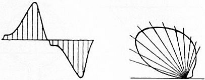
Fig. 1. Fig. 2.
In a polar diagram (fig. 2) a number of radial lines are drawn from a point at small equiangular intervals, and on these lines are set off lengths proportional to the current value of a periodic current at corresponding intervals during one complete period represented by four right angles. The extremities of these radii delineate a polar curve. The polar form of a simple sine current is obviously a circle drawn through the origin. As a consequence of Fourier’s theorem it follows that any periodic curve having any wave form can be imitated by the superposition of simple sine currents differing in maximum value and in phase.
Definitions of Unit Electric Current.—In electrokinetic investigations we are most commonly limited to the cases of unidirectional continuous and constant currents (C.C. or D.C.), or of simple periodic currents, or alternating currents of sine form (A.C.). A continuous electric current is measured either by the magnetic effect it produces at some point outside its circuit, or by the amount of electrochemical decomposition it can perform in a given time on a selected standard electrolyte. Limiting our consideration to the case of linear currents or currents flowing in thin cylindrical wires, a definition may be given in the first place of the unit electric current in the centimetre, gramme, second (C.G.S.) of electromagnetic measurement (see Units, Physical). H.C. Oersted discovered in 1820 that a straight wire conveying an electric current is surrounded by a magnetic field the lines of which are self-closed lines embracing the electric circuit (see Electricity and Electromagnetism). The unit current in the electromagnetic system of measurement is defined as the current which, flowing in a thin wire bent into the form of a circle of one centimetre in radius, creates a magnetic field having a strength of 2π units at the centre of the circle, and therefore would exert a mechanical force of 2π dynes on a unit magnetic pole placed at that point (see Magnetism). Since the length of the circumference of the circle of unit radius is 2π units, this is equivalent to stating that the unit current on the electromagnetic C.G.S. system is a current such that unit length acts on unit magnetic pole with a unit force at a unit of distance. Another definition, called the electrostatic unit of current, is as follows: Let any conductor be charged with electricity and discharged through a thin wire at such a rate that one electrostatic unit of quantity (see Electrostatics) flows past any section of the wire in one unit of time. The electromagnetic unit of current defined as above is 3 × 10¹⁰ times larger than the electrostatic unit.
In the selection of a practical unit of current it was considered that the electromagnetic unit was too large for most purposes, whilst the electrostatic unit was too small; hence a practical unit of current called 1 ampere was selected, intended originally to be 1⁄10 of the absolute electromagnetic C.G.S. unit of current as above defined. The practical unit of current, called the international ampere, is, however, legally defined at the present time as the continuous unidirectional current which when flowing through a neutral solution of silver nitrate deposits in one second on the cathode or negative pole 0.001118 of a gramme of silver. There is reason to believe that the international unit is smaller by about one part in a thousand, or perhaps by one part in 800, than the theoretical ampere defined as 1⁄10 part of the absolute electromagnetic unit. A periodic or alternating current is said to have a value of 1 ampere if when passed through a fine wire it produces in the same time the same heat as a unidirectional continuous current of 1 ampere as above electrochemically defined. In the case of a simple periodic alternating current having a simple sine wave form, the maximum value is equal to that of the equiheating continuous current multiplied by √2. This equiheating continuous current is called the effective or root-mean-square (R.M.S.) value of the alternating one.
Resistance.—A current flows in a circuit in virtue of an electromotive force (E.M.F.), and the numerical relation between the current and E.M.F. is determined by three qualities of the circuit called respectively, its resistance (R), inductance (L), and capacity (C). If we limit our consideration to the case of continuous unidirectional conduction currents, then the relation between current and E.M.F. is defined by Ohm’s law, which states that the numerical value of the current is obtained as the quotient of the electromotive force by a certain constant of the circuit called its resistance, which is a function of the geometrical form of the circuit, of its nature, i.e. material, and of its temperature, but is independent of the electromotive force or current. The resistance (R) is measured in units called ohms and the electromotive force in volts (V); hence for a continuous current the value of the current in amperes (A) is obtained as the quotient of the electromotive force acting in the circuit reckoned in volts by the resistance in ohms, or A = V/R. Ohm established his law by a course of reasoning which was similar to that on which J.B.J. Fourier based his investigations on the uniform motion of heat in a conductor. As a matter of fact, however, Ohm’s law merely states the direct proportionality of steady current to steady electromotive force in a circuit, and asserts that this ratio is governed by the numerical value of a quality of the conductor, called its resistance, which is independent of the current, provided that a correction is made for the change of temperature produced by the current. Our belief, however, in its universality and accuracy rests upon the close agreement between deductions made from it and observational results, and although it is not derivable from any more fundamental principle, it is yet one of the most certainly ascertained laws of electrokinetics.
Ohm’s law not only applies to the circuit as a whole but to any part of it, and provided the part selected does not contain a source of electromotive force it may be expressed as follows:—The difference of potential (P.D.) between any two points of a circuit including a resistance R, but not including any source of electromotive force, is proportional to the product of the resistance and the current i in the element, provided the conductor remains at the same temperature and the current is constant and unidirectional. If the current is varying we have, however, to take into account the electromotive force (E.M.F.) produced by this variation, and the product Ri is then equal to the difference between the observed P.D. and induced E.M.F.
We may otherwise define the resistance of a circuit by saying that it is that physical quality of it in virtue of which energy is dissipated as heat in the circuit when a current flows through it. The power communicated to any electric circuit when a current i is created in it by a continuous unidirectional electromotive force E is equal to Ei, and the energy dissipated as heat in that circuit by the conductor in a small interval of time dt is measured by Ei dt. Since by Ohm’s law E = Ri, where R is the resistance of the circuit, it follows that the energy dissipated as heat per unit of time in any circuit is numerically represented by Ri², and therefore the resistance is measured by the heat produced per unit of current, provided the current is unvarying.
Inductance.—As soon as we turn our attention, however, to alternating or periodic currents we find ourselves compelled to take into account another quality of the circuit, called its “inductance.” This may be defined as that quality in virtue of which energy is stored up in connexion with the circuit in a magnetic form. It can be experimentally shown that a current cannot be created instantaneously in a circuit by any finite electromotive force, and that when once created it cannot be annihilated instantaneously. The circuit possesses a quality analogous to the inertia of matter. If a current i is flowing in a circuit at any moment, the energy stored up in connexion with the circuit is measured by ½Li², where L, the inductance of the circuit, is related to the current in the same manner as the quantity called the mass of a body is related to its velocity in the expression for the ordinary kinetic energy, viz. ½Mv². The rate at which this conserved energy varies with the current is called the “electrokinetic momentum” of this circuit (= Li). Physically interpreted this quantity signifies the number of lines of magnetic flux due to the current itself which are self-linked with its own circuit.
Magnetic Force and Electric Currents.—In the case of every circuit conveying a current there is a certain magnetic force (see Magnetism) at external points which can in some instances be calculated. Laplace proved that the magnetic force due to an element of length dS of a circuit conveying a current I at a point P at a distance r from the element is expressed by IdS sin θ/r², where θ is the angle between the direction of the current element and that drawn between the element and the point. This force is in a direction perpendicular to the radius vector and to the plane containing it and the element of current. Hence the determination of the magnetic force due to any circuit is reduced to a summation of the effects due to all the elements of length. For instance, the magnetic force at the centre of a circular circuit of radius r carrying a steady current I is 2πI/r, since all elements are at the same distance from the centre. In the same manner, if we take a point in a line at right angles to the plane of the circle through its centre and at a distance d, the magnetic force along this line is expressed by 2πr²I / (r² + d²)3⁄2. Another important case is that of an infinitely long straight current. By summing up the magnetic force due to each element at any point P outside the continuous straight current I, and at a distance d from it, we can show that it is equal to 2I/d or is inversely proportional to the distance of the point from the wire. In the above formula the current I is measured in absolute electromagnetic units. If we reckon the current in amperes A, then I = A/10.
It is possible to make use of this last formula, coupled with an experimental fact, to prove that the magnetic force due to an element of current varies inversely as the square of the distance. If a flat circular disk is suspended so as to be free to rotate round a straight current which passes through its centre, and two bar magnets are placed on it with their axes in line with the current, it is found that the disk has no tendency to rotate round the current. This proves that the force on each magnetic pole is inversely as its distance from the current. But it can be shown that this law of action of the whole infinitely long straight current is a mathematical consequence of the fact that each element of the current exerts a magnetic force which varies inversely as the square of the distance. If the current flows N times round the circuit instead of once, we have to insert NA/10 in place of I in all the above formulae. The quantity NA is called the “ampere-turns” on the circuit, and it is seen that the magnetic field at any point outside a circuit is proportional to the ampere-turns on it and to a function of its geometrical form and the distance of the point.
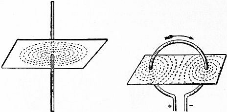
Fig. 3. Fig. 4.
There is therefore a distribution of magnetic force in the field of every current-carrying conductor which can be delineated by lines of magnetic force and rendered visible to the eye by iron filings (see Magnetism). If a copper wire is passed vertically through a hole in a card on which iron filings are sprinkled, and a strong electric current is sent through the circuit, the filings arrange themselves in concentric circular lines making visible the paths of the lines of magnetic force (fig. 3). In the same manner, by passing a circular wire through a card and sending a strong current through the wire we can employ iron filings to delineate for us the form of the lines of magnetic force (fig. 4). In all cases a magnetic pole of strength M, placed in the field of an electric current, is urged along the lines of force with a mechanical force equal to MH, where H is the magnetic force. If then we carry a unit magnetic pole against the direction in which it would naturally move we do work. The lines of magnetic force embracing a current-carrying conductor are always loops or endless lines.
The work done in carrying a unit magnetic pole once round a circuit conveying a current is called the “line integral of magnetic force” along that path. If, for instance, we carry a unit pole in a circular path of radius r once round an infinitely long straight filamentary current I, the line integral is 4πI. It is easy to prove that this is a general law, and that if we have any currents flowing in a conductor the line integral of magnetic force taken once round a path linked with the current circuit is 4π times the total current flowing through the circuit. Let us apply this to the case of an endless solenoid. If a copper wire insulated or covered with cotton or silk is twisted round a thin rod so as to make a close spiral, this forms a “solenoid,” and if the solenoid is bent round so that its two ends come together we have an endless solenoid. Consider such a solenoid of mean length l and N turns of wire. If it is made endless, the magnetic force H is the same everywhere along the central axis and the line integral along the axis is Hl. If the current is denoted by I, then NI is the total current, and accordingly 4πNI = Hl, or H = 4πNI/l. For a thin endless solenoid the axial magnetic force is therefore 4π times the current-turns per unit of length. This holds good also for a long straight solenoid provided its length is large compared with its diameter. It can be shown that if insulated wire is wound round a sphere, the turns being all parallel to lines of latitude, the magnetic force in the interior is constant and the lines of force therefore parallel. The magnetic force at a point outside a conductor conveying a current can by various means be measured or compared with some other standard magnetic forces, and it becomes then a means of measuring the current. Instruments called galvanometers and ammeters for the most part operate on this principle.
Thermal Effects of Currents.—J.P. Joule proved that the heat produced by a constant current in a given time in a wire having a constant resistance is proportional to the square of the strength of the current. This is known as Joule’s law, and it follows, as already shown, as an immediate consequence of Ohm’s law and the fact that the power dissipated electrically in a conductor, when an electromotive force E is applied to its extremities, producing thereby a current I in it, is equal to EI.
If the current is alternating or periodic, the heat produced in any time T is obtained by taking the sum at equidistant intervals of time of all the values of the quantities Ri²dt, where dt represents a small interval of time and i is the current at that instant. The quantity T−1 ∫ T0 i²dt is called the mean-square-value of the variable current, i being the instantaneous value of the current, that is, its value at a particular instant or during a very small interval of time dt. The square root of the above quantity, or
[ T−1 ∫ T0 i²dt ]1/2,
is called the root-mean-square-value, or the effective value of the current, and is denoted by the letters R.M.S.
Currents have equal heat-producing power in conductors of identical resistance when they have the same R.M.S. values. Hence periodic or alternating currents can be measured as regards their R.M.S. value by ascertaining the continuous current which produces in the same time the same heat in the same conductor as the periodic current considered. Current measuring instruments depending on this fact, called hot-wire ammeters, are in common use, especially for measuring alternating currents. The maximum value of the periodic current can only be determined from the R.M.S. value when we know the wave form of the current. The thermal effects of electric currents in conductors are dependent upon the production of a state of equilibrium between the heat produced electrically in the wire and the causes operative in removing it. If an ordinary round wire is heated by a current it loses heat, (1) by radiation, (2) by air convection or cooling, and (3) by conduction of heat out of the ends of the wire. Generally speaking, the greater part of the heat removal is effected by radiation and convection.
If a round sectioned metallic wire of uniform diameter d and length l made of a material of resistivity ρ has a current of A amperes passed through it, the heat in watts produced in any time t seconds is represented by the value of 4A²ρlt / 109πd², where d and l must be measured in centimetres and ρ in absolute C.G.S. electromagnetic units. The factor 109 enters because one ohm is 109 absolute electromagnetic C.G.S. units (see Units, Physical). If the wire has an emissivity e, by which is meant that e units of heat reckoned in joules or watt-seconds are radiated per second from unit of surface, then the power removed by radiation in the time t is expressed by πdlet. Hence when thermal equilibrium is established we have 4A²ρlt / 109πd² = πdlet, or A² = 109π²ed³ / 4ρ. If the diameter of the wire is reckoned in mils (1 mil = .001 in.), and if we take e to have a value 0.1, an emissivity which will generally bring the wire to about 60° C., we can put the above formula in the following forms for circular sectioned copper, iron or platinoid wires, viz.
A = √d³ / 500 for copper wires A = √d³ / 4000 for iron wires A = √d³ / 5000 for platinoid wires.
These expressions give the ampere value of the current which will bring bare, straight or loosely coiled wires of d mils in diameter to about 60° C. when the steady state of temperature is reached. Thus, for instance, a bare straight copper wire 50 mils in diameter (= 0.05 in.) will be brought to a steady temperature of about 60° C. if a current of √50³/500 = √250 = 16 amperes (nearly) is passed through it, whilst a current of √25 = 5 amperes would bring a platinoid wire to about the same temperature.
A wire has therefore a certain safe current-carrying capacity which is determined by its specific resistance and emissivity, the latter being fixed by its form, surface and surroundings. The emissivity increases with the temperature, else no state of thermal equilibrium could be reached. It has been found experimentally that whilst for fairly thick wires from 8 to 60 mils in diameter the safe current varies approximately as the 1.5th power of the diameter, for fine wires of 1 to 3 mils it varies more nearly as the diameter.
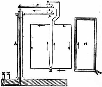
Fig. 5.
Action of one Current on Another.—The investigations of Ampère in connexion with electric currents are of fundamental importance in electrokinetics. Starting from the discovery of Oersted, Ampère made known the correlative fact that not only is there a mechanical action between a current and a magnet, but that two conductors conveying electric currents exert mechanical forces on each other. Ampère devised ingenious methods of making one portion of a circuit movable so that he might observe effects of attraction or repulsion between this circuit and some other fixed current. He employed for this purpose an astatic circuit B, consisting of a wire bent into a double rectangle round which a current flowed first in one and then in the opposite direction (fig. 5). In this way the circuit was removed from the action of the earth’s magnetic field, and yet one portion of it could be submitted to the action of any other circuit C. The astatic circuit was pivoted by suspending it in mercury cups q, p, one of which was in electrical connexion with the tubular support A, and the other with a strong insulated wire passing up it.
Ampère devised certain crucial experiments, and the theory deduced from them is based upon four facts and one assumption.2 He showed (1) that wire conveying a current bent back on itself produced no action upon a proximate portion of a movable astatic circuit; (2) that if the return wire was bent zig-zag but close to the outgoing straight wire the circuit produced no action on the movable one, showing that the effect of an element of the circuit was proportional to its projected length; (3) that a closed circuit cannot cause motion in an element of another circuit free to move in the direction of its length; and (4) that the action of two circuits on one and the same movable circuit was null if one of the two fixed circuits was n times greater than the other but n times further removed from the movable circuit. From this last experiment by an ingenious line of reasoning he proved that the action of an element of current on another element of current varies inversely as a square of their distance. These experiments enabled him to construct a mathematical expression of the law of action between two elements of conductors conveying currents. They also enabled him to prove that an element of current may be resolved like a force into components in different directions, also that the force produced by any element of the circuit on an element of any other circuit was perpendicular to the line joining the elements and inversely as the square of their distance. Also he showed that this force was an attraction if the currents in the elements were in the same direction, but a repulsion if they were in opposite directions. From these experiments and deductions from them he built up a complete formula for the action of one element of a current of length dS of one conductor conveying a current I upon another element dS′ of another circuit conveying another current I′ the elements being at a distance apart equal to r.
If θ and θ’ are the angles the elements make with the line joining them, and φ the angle they make with one another, then Ampère’s expression for the mechanical force f the elements exert on one another is
f = 2II′r−2 {cos φ − 3⁄2 cos θ cos θ′} dSdS′.
This law, together with that of Laplace already mentioned, viz. that the magnetic force due to an element of length dS of a current I at a distance r, the element making an angle θ with the radius vector o is IdS sin θ/r², constitute the fundamental laws of electrokinetics.
Ampère applied these with great mathematical skill to elucidate the mechanical actions of currents on each other, and experimentally confirmed the following deductions: (1) Currents in parallel circuits flowing in the same direction attract each other, but if in opposite directions repel each other. (2) Currents in wires meeting at an angle attract each other more into parallelism if both flow either to or from the angle, but repel each other more widely apart if they are in opposite directions. (3) A current in a small circular conductor exerts a magnetic force in its centre perpendicular to its plane and is in all respects equivalent to a magnetic shell or a thin circular disk of steel so magnetized that one face is a north pole and the other a south pole, the product of the area of the circuit and the current flowing in it determining the magnetic moment of the element. (4) A closely wound spiral current is equivalent as regards external magnetic force to a polar magnet, such a circuit being called a finite solenoid. (5) Two finite solenoid circuits act on each other like two polar magnets, exhibiting actions of attraction or repulsion between their ends.
Ampère’s theory was wholly built up on the assumption of action at a distance between elements of conductors conveying the electric currents. Faraday’s researches and the discovery of the fact that the insulating medium is the real seat of the operations necessitates a change in the point of view from which we regard the facts discovered by Ampère. Maxwell showed that in any field of magnetic force there is a tension along the lines of force and a pressure at right angles to them; in other words, lines of magnetic force are like stretched elastic threads which tend to contract.3 If, therefore, two conductors lie parallel and have currents in them in the same direction they are impressed by a certain number of lines of magnetic force which pass round the two conductors, and it is the tendency of these to contract which draws the circuits together. If, however, the currents are in opposite directions then the lateral pressure of the similarly contracted lines of force between them pushes the conductors apart. Practical application of Ampère’s discoveries was made by W.E. Weber in inventing the electrodynamometer, and later Lord Kelvin devised ampere balances for the measurement of electric currents based on the attraction between coils conveying electric currents.
Induction of Electric Currents.—Faraday4 in 1831 made the important discovery of the induction of electric currents (see Electricity). If two conductors are placed parallel to each other, and a current in one of them, called the primary, started or stopped or changed in strength, every such alteration causes a transitory current to appear in the other circuit, called the secondary. This is due to the fact that as the primary current increases or decreases, its own embracing magnetic field alters, and lines of magnetic force are added to or subtracted from its fields. These lines do not appear instantly in their place at a distance, but are propagated out from the wire with a velocity equal to that of light; hence in their outward progress they cut through the secondary circuit, just as ripples made on the surface of water in a lake by throwing a stone on to it expand and cut through a stick held vertically in the water at a distance from the place of origin of the ripples. Faraday confirmed this view of the phenomena by proving that the mere motion of a wire transversely to the lines of magnetic force of a permanent magnet gave rise to an induced electromotive force in the wire. He embraced all the facts in the single statement that if there be any circuit which by movement in a magnetic field, or by the creation or change in magnetic fields round it, experiences a change in the number of lines of force linked with it, then an electromotive force is set up in that circuit which is proportional at any instant to the rate at which the total magnetic flux linked with it is changing. Hence if Z represents the total number of lines of magnetic force linked with a circuit of N turns, then −N (dZ/dt) represents the electromotive force set up in that circuit. The operation of the induction coil (q.v.) and the transformer (q.v.) are based on this discovery. Faraday also found that if a copper disk A (fig. 6) is rotated between the poles of a magnet NO so that the disk moves with its plane perpendicular to the lines of magnetic force of the field, it has created in it an electromotive force directed from the centre to the edge or vice versa. The action of the dynamo (q.v.) depends on similar processes, viz. the cutting of the lines of magnetic force of a constant field produced by certain magnets by certain moving conductors called armature bars or coils in which an electromotive force is thereby created.
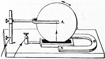
Fig 6.
In 1834 H.F.E. Lenz enunciated a law which connects together the mechanical actions between electric circuits discovered by Ampère and the induction of electric currents discovered by Faraday. It is as follows: If a constant current flows in a primary circuit P, and if by motion of P a secondary current is created in a neighbouring circuit S, the direction of the secondary current will be such as to oppose the relative motion of the circuits. Starting from this, F.E. Neumann founded a mathematical theory of induced currents, discovering a quantity M, called the “potential of one circuit on another,” or generally their “coefficient of mutual inductance.” Mathematically M is obtained by taking the sum of all such quantities as ƒƒ dSdS′ cos φ/r, where dS and dS′ are the elements of length of the two circuits, r is their distance, and φ is the angle which they make with one another; the summation or integration must be extended over every possible pair of elements. If we take pairs of elements in the same circuit, then Neumann’s formula gives us the coefficient of self-induction of the circuit or the potential of the circuit on itself. For the results of such calculations on various forms of circuit the reader must be referred to special treatises.
H. von Helmholtz, and later on Lord Kelvin, showed that the facts of induction of electric currents discovered by Faraday could have been predicted from the electrodynamic actions discovered by Ampère assuming the principle of the conservation of energy. Helmholtz takes the case of a circuit of resistance R in which acts an electromotive force due to a battery or thermopile. Let a magnet be in the neighbourhood, and the potential of the magnet on the circuit be V, so that if a current I existed in the circuit the work done on the magnet in the time dt is I (dV/dt)dt. The source of electromotive force supplies in the time dt work equal to EIdt, and according to Joule’s law energy is dissipated equal to RI²dt. Hence, by the conservation of energy,
EIdt = RI²dt + I (dV/dt) dt.
If then E = 0, we have I = −(dV/dt) / R, or there will be a current due to an induced electromotive force expressed by −dV/dt. Hence if the magnet moves, it will create a current in the wire provided that such motion changes the potential of the magnet with respect to the circuit. This is the effect discovered by Faraday.5
Oscillatory Currents.—In considering the motion of electricity in conductors we find interesting phenomena connected with the discharge of a condenser or Leyden jar (q.v.). This problem was first mathematically treated by Lord Kelvin in 1853 (Phil. Mag., 1853, 5, p. 292).
If a conductor of capacity C has its terminals connected by a wire of resistance R and inductance L, it becomes important to consider the subsequent motion of electricity in the wire. If Q is the quantity of electricity in the condenser initially, and q that at any time t after completing the circuit, then the energy stored up in the condenser at that instant is ½q² / C, and the energy associated with the circuit is ½L (dq/dt)², and the rate of dissipation of energy by resistance is R (dq/dt)², since dq/dt = i is the discharge current. Hence we can construct an equation of energy which expresses the fact that at any instant the power given out by the condenser is partly stored in the circuit and partly dissipated as heat in it. Mathematically this is expressed as follows:—
− d [ ½ q² ] = d [ ½L ( dq ) ² ] + R ( dq ) ²
dt C dt dt dt
or
d²q + R dq + 1 q = 0.
dt² L dt LC
The above equation has two solutions according as R² / 4L² is greater or less than 1/LC. In the first case the current i in the circuit can be expressed by the equation
i = Q α² + β² e−αt (eβt − e−βt),
2β
where α = R/2L, β = √(R²/4L² − 1/LC), Q is the value of q when t = 0, and e is the base of Napierian logarithms; and in the second case by the equation
i = Q α²+β² e−αt sin βt
β
where
α = R/2L, and β = √ 1 − R² .
LC 4L²
These expressions show that in the first case the discharge current of the jar is always in the same direction and is a transient unidirectional current. In the second case, however, the current is an oscillatory current gradually decreasing in amplitude, the frequency n of the oscillation being given by the expression
n = 1 √ 1 − R² .
2π LC 4L²
In those cases in which the resistance of the discharge circuit is very small, the expression for the frequency n and for the time period of oscillation R take the simple forms n = 1, 2π √LC, or T = 1/n = 2π √LC.
The above investigation shows that if we construct a circuit consisting of a condenser and inductance placed in series with one another, such circuit has a natural electrical time period of its own in which the electrical charge in it oscillates if disturbed. It may therefore be compared with a pendulum of any kind which when displaced oscillates with a time period depending on its inertia and on its restoring force.
The study of these electrical oscillations received a great impetus after H.R. Hertz showed that when taking place in electric circuits of a certain kind they create electromagnetic waves (see Electric Waves) in the dielectric surrounding the oscillator, and an additional interest was given to them by their application to telegraphy. If a Leyden jar and a circuit of low resistance but some inductance in series with it are connected across the secondary spark gap of an induction coil, then when the coil is set in action we have a series of bright noisy sparks, each of which consists of a train of oscillatory electric discharges from the jar. The condenser becomes charged as the secondary electromotive force of the coil is created at each break of the primary current, and when the potential difference of the condenser coatings reaches a certain value determined by the spark-ball distance a discharge happens. This discharge, however, is not a single movement of electricity in one direction but an oscillatory motion with gradually decreasing amplitude. If the oscillatory spark is photographed on a revolving plate or a rapidly moving film, we have evidence in the photograph that such a spark consists of numerous intermittent sparks gradually becoming feebler. As the coil continues to operate, these trains of electric discharges take place at regular intervals. We can cause a train of electric oscillations in one circuit to induce similar oscillations in a neighbouring circuit, and thus construct an oscillation transformer or high frequency induction coil.
Alternating Currents.—The study of alternating currents of electricity began to attract great attention towards the end of the 19th century by reason of their application in electrotechnics and especially to the transmission of power. A circuit in which a simple periodic alternating current flows is called a single phase circuit. The important difference between such a form of current flow and steady current flow arises from the fact that if the circuit has inductance then the periodic electric current in it is not in step with the terminal potential difference or electromotive force acting in the circuit, but the current lags behind the electromotive force by a certain fraction of the periodic time called the “phase difference.” If two alternating currents having a fixed difference in phase flow in two connected separate but related circuits, the two are called a two-phase current. If three or more single-phase currents preserving a fixed difference of phase flow in various parts of a connected circuit, the whole taken together is called a polyphase current. Since an electric current is a vector quantity, that is, has direction as well as magnitude, it can most conveniently be represented by a line denoting its maximum value, and if the alternating current is a simple periodic current then the root-mean-square or effective value of the current is obtained by dividing the maximum value by √2. Accordingly when we have an electric circuit or circuits in which there are simple periodic currents we can draw a vector diagram, the lines of which represent the relative magnitudes and phase differences of these currents.
A vector can most conveniently be represented by a symbol such as a + ib, where a stands for any length of a units measured horizontally and b for a length b units measured vertically, and the symbol ι is a sign of perpendicularity, and equivalent analytically6 to √−1. Accordingly if E represents the periodic electromotive force (maximum value) acting in a circuit of resistance R and inductance L and frequency n, and if the current considered as a vector is represented by I, it is easy to show that a vector equation exists between these quantities as follows:—
E = RI + ι2πnLI.
Since the absolute magnitude of a vector a + ιb is √(a² + b²), it follows that considering merely magnitudes of current and electromotive force and denoting them by symbols (E) (I), we have the following equation connecting (I) and (E):—
(I) = (E) / √R² + p²L²,
where p stands for 2πn. If the above equation is compared with the symbolic expression of Ohm’s law, it will be seen that the quantity √(R² + p²L²) takes the place of resistance R in the expression of Ohm. This quantity √(R² + p²L²) is called the “impedance” of the alternating circuit. The quantity pL is called the “reactance” of the alternating circuit, and it is therefore obvious that the current in such a circuit lags behind the electromotive force by an angle, called the angle of lag, the tangent of which is pL/R.
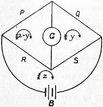
Fig. 7.
Currents in Networks of Conductors.—In dealing with problems connected with electric currents we have to consider the laws which govern the flow of currents in linear conductors (wires), in plane conductors (sheets), and throughout the mass of a material conductor.7 In the first case consider the collocation of a number of linear conductors, such as rods or wires of metal, joined at their ends to form a network of conductors. The network consists of a number of conductors joining certain points and forming meshes. In each conductor a current may exist, and along each conductor there is a fall of potential, or an active electromotive force may be acting in it. Each conductor has a certain resistance. To find the current in each conductor when the individual resistances and electromotive forces are given, proceed as follows:—Consider any one mesh. The sum of all the electromotive forces which exist in the branches bounding that mesh must be equal to the sum of all the products of the resistances into the currents flowing along them, or Σ(E) = Σ(C.R.). Hence if we consider each mesh as traversed by imaginary currents all circulating in the same direction, the real currents are the sums or differences of these imaginary cyclic currents in each branch. Hence we may assign to each mesh a cycle symbol x, y, z, &c., and form a cycle equation. Write down the cycle symbol for a mesh and prefix as coefficient the sum of all the resistances which bound that cycle, then subtract the cycle symbols of each adjacent cycle, each multiplied by the value of the bounding or common resistances, and equate this sum to the total electromotive force acting round the cycle. Thus if x y z are the cycle currents, and a b c the resistances bounding the mesh x, and b and c those separating it from the meshes y and z, and E an electromotive force in the branch a, then we have formed the cycle equation x(a + b + c) − by − cz = E. For each mesh a similar equation may be formed. Hence we have as many linear equations as there are meshes, and we can obtain the solution for each cycle symbol, and therefore for the current in each branch. The solution giving the current in such branch of the network is therefore always in the form of the quotient of two determinants. The solution of the well-known problem of finding the current in the galvanometer circuit of the arrangement of linear conductors called Wheatstone’s Bridge is thus easily obtained. For if we call the cycles (see fig. 7) (x + y), y and z, and the resistances P, Q, R, S, G and B, and if E be the electromotive force in the battery circuit, we have the cycle equations
(P + G + R) (x + y) − Gy − Rz = 0, (Q + G + S)y − G (x + y) − Sz = 0, (R + S + B)z − R (x + y) − Sy = E.
From these we can easily obtain the solution for (x + y) − y = x, which is the current through the galvanometer circuit in the form
x = E (PS − RQ) Δ.
where Δ is a certain function of P, Q, R, S, B and G.
Currents in Sheets.—In the case of current flow in plane sheets, we have to consider certain points called sources at which the current flows into the sheet, and certain points called sinks at which it leaves. We may investigate, first, the simple case of one source and one sink in an infinite plane sheet of thickness δ and conductivity k. Take any point P in the plane at distances R and r from the source and sink respectively. The potential V at P is obviously given by
V = Q log e r1 ,
2πkδ r2
where Q is the quantity of electricity supplied by the source per second. Hence the equation to the equipotential curve is r1r2 = a constant.
If we take a point half-way between the sink and the source as the origin of a system of rectangular co-ordinates, and if the distance between sink and source is equal to p, and the line joining them is taken as the axis of x, then the equation to the equipotential line is
y² + (x + p)² = a constant.
y² + (x − p)²
This is the equation of a family of circles having the axis of y for a common radical axis, one set of circles surrounding the sink and another set of circles surrounding the source. In order to discover the form of the stream of current lines we have to determine the orthogonal trajectories to this family of coaxial circles. It is easy to show that the orthogonal trajectory of the system of circles is another system of circles all passing through the sink and the source, and as a corollary of this fact, that the electric resistance of a circular disk of uniform thickness is the same between any two points taken anywhere on its circumference as sink and source. These equipotential lines may be delineated experimentally by attaching the terminals of a battery or batteries to small wires which touch at various places a sheet of tinfoil. Two wires attached to a galvanometer may then be placed on the tinfoil, and one may be kept stationary and the other may be moved about, so that the galvanometer is not traversed by any current. The moving terminal then traces out an equipotential curve. If there are n sinks and sources in a plane conducting sheet, and if r, r′, r″ be the distances of any point from the sinks, and t, t′, t″ the distances of the sources, then
r r′ r″ ... = a constant,
t t′ t″ ...
is the equation to the equipotential lines. The orthogonal trajectories or stream lines have the equation
Σ (θ − θ′) = a constant,
where θ and θ′ are the angles which the lines drawn from any point in the plane to the sink and corresponding source make with the line joining that sink and source. Generally it may be shown that if there are any number of sinks and sources in an infinite plane-conducting sheet, and if r, θ are the polar co-ordinates of any one, then the equation to the equipotential surfaces is given by the equation
Σ (A log e r) = a constant,
where A is a constant; and the equation to the stream of current lines is
Σ (θ) = a constant.
In the case of electric flow in three dimensions the electric potential must satisfy Laplace’s equation, and a solution is therefore found in the form Σ (A/r) = a constant, as the equation to an equipotential surface, where r is the distance of any point on that surface from a source or sink.
Convection Currents.—The subject of convection electric currents has risen to great importance in connexion with modern electrical investigations. The question whether a statically electrified body in motion creates a magnetic field is of fundamental importance. Experiments to settle it were first undertaken in the year 1876 by H.A. Rowland, at a suggestion of H. von Helmholtz.8 After preliminary experiments, Rowland’s first apparatus for testing this hypothesis was constructed, as follows:—An ebonite disk was covered with radial strips of gold-leaf and placed between two other metal plates which acted as screens. The disk was then charged with electricity and set in rapid rotation. It was found to affect a delicately suspended pair of astatic magnetic needles hung in proximity to the disk just as would, by Oersted’s rule, a circular electric current coincident with the periphery of the disk. Hence the statically-charged but rotating disk becomes in effect a circular electric current.
The experiments were repeated and confirmed by W.C. Röntgen (Wied. Ann., 1888, 35, p. 264; 1890, 40, p. 93) and by F. Himstedt (Wied. Ann., 1889, 38, p. 560). Later V. Crémieu again repeated them and obtained negative results (Com. rend., 1900, 130, p. 1544, and 131, pp. 578 and 797; 1901, 132, pp. 327 and 1108). They were again very carefully reconducted by H. Pender (Phil. Mag., 1901, 2, p. 179) and by E.P. Adams (id. ib., 285). Pender’s work showed beyond any doubt that electric convection does produce a magnetic effect. Adams employed charged copper spheres rotating at a high speed in place of a disk, and was able to prove that the rotation of such spheres produced a magnetic field similar to that due to a circular current and agreeing numerically with the theoretical value. It has been shown by J.J. Thomson (Phil. Mag., 1881, 2, p. 236) and O. Heaviside (Electrical Papers, vol. ii. p. 205) that an electrified sphere, moving with a velocity v and carrying a quantity of electricity q, should produce a magnetic force H, at a point at a distance ρ from the centre of the sphere, equal to qv sin θ/ρ², where θ is the angle between the direction of ρ and the motion of the sphere. Adams found the field produced by a known electric charge rotating at a known speed had a strength not very different from that predetermined by the above formula. An observation recorded by R.W. Wood (Phil. Mag., 1902, 2, p. 659) provides a confirmatory fact. He noticed that if carbon-dioxide strongly compressed in a steel bottle is allowed to escape suddenly the cold produced solidifies some part of the gas, and the issuing jet is full of particles of carbon-dioxide snow. These by friction against the nozzle are electrified positively. Wood caused the jet of gas to pass through a glass tube 2.5 mm. in diameter, and found that these particles of electrified snow were blown through it with a velocity of 2000 ft. a second. Moreover, he found that a magnetic needle hung near the tube was deflected as if held near an electric current. Hence the positively electrified particles in motion in the tube create a magnetic field round it.
Nature of an Electric Current.—The question, What is an electric current? is involved in the larger question of the nature of electricity. Modern investigations have shown that negative electricity is identical with the electrons or corpuscles which are components of the chemical atom (see Matter and Electricity). Certain lines of argument lead to the conclusion that a solid conductor is not only composed of chemical atoms, but that there is a certain proportion of free electrons present in it, the electronic density or number per unit of volume being determined by the material, its temperature and other physical conditions. If any cause operates to add or remove electrons at one point there is an immediate diffusion of electrons to re-establish equilibrium, and this electronic movement constitutes an electric current. This hypothesis explains the reason for the identity between the laws of diffusion of matter, of heat and of electricity. Electromotive force is then any cause making or tending to make an inequality of electronic density in conductors, and may arise from differences of temperature, i.e. thermoelectromotive force (see Thermoelectricity), or from chemical action when part of the circuit is an electrolytic conductor, or from the movement of lines of magnetic force across the conductor.
Bibliography.—For additional information the reader may be referred to the following books: M. Faraday, Experimental Researches in Electricity (3 vols., London, 1839, 1844, 1855); J. Clerk Maxwell, Electricity and Magnetism (2 vols., Oxford, 1892); W. Watson and S.H. Burbury, Mathematical Theory of Electricity and Magnetism, vol. ii. (Oxford, 1889); E. Mascart and J. Joubert, A Treatise on Electricity and Magnetism (2 vols., London, 1883); A. Hay, Alternating Currents (London, 1905); W.G. Rhodes, An Elementary Treatise on Alternating Currents (London, 1902); D.C. Jackson and J.P. Jackson, Alternating Currents and Alternating Current Machinery (1896, new ed. 1903); S.P. Thompson, Polyphase Electric Currents (London, 1900); Dynamo-Electric Machinery, vol. ii., “Alternating Currents” (London, 1905); E.E. Fournier d’Albe, The Electron Theory (London, 1906).
(J. A. F.)
1 See J.A. Fleming, The Alternate Current Transformer, vol. i. p. 519.
2 See Maxwell, Electricity and Magnetism, vol. ii. chap. ii.
3 See Maxwell, Electricity and Magnetism, vol. ii. 642.
4 Experimental Researches, vol. i. ser. 1.
5 See Maxwell, Electricity and Magnetism, vol. ii. § 542, p. 178.
6 See W.G. Rhodes, An Elementary Treatise on Alternating Currents (London, 1902), chap. vii.
7 See J.A. Fleming, “Problems on the Distribution of Electric Currents in Networks of Conductors,” Phil. Mag. (1885), or Proc. Phys. Soc. Lond. (1885), 7; also Maxwell, Electricity and Magnetism (2nd ed.), vol. i. p. 374, § 280, 282b.
8 See Berl. Acad. Ber., 1876, p. 211; also H.A. Rowland and C.T. Hutchinson, “On the Electromagnetic Effect of Convection Currents,” Phil. Mag., 1889, 27, p. 445.
ELECTROLIER, a fixture, usually pendent from the ceiling, for holding electric lamps. The word is analogous to chandelier, from which indeed it was formed.
ELECTROLYSIS (formed from Gr. λύειν, to loosen). When the passage of an electric current through a substance is accompanied by definite chemical changes which are independent of the heating effects of the current, the process is known as electrolysis, and the substance is called an electrolyte. As an example we may take the case of a solution of a salt such as copper sulphate in water, through which an electric current is passed between copper plates. We shall then observe the following phenomena. (1) The bulk of the solution is unaltered, except that its temperature may be raised owing to the usual heating effect which is proportional to the square of the strength of the current. (2) The copper plate by which the current is said to enter the solution, i.e. the plate attached to the so-called positive terminal of the battery or other source of current, dissolves away, the copper going into solution as copper sulphate. (3) Copper is deposited on the surface of the other plate, being obtained from the solution. (4) Changes in concentration are produced in the neighbourhood of the two plates or electrodes. In the case we have chosen, the solution becomes stronger near the anode, or electrode at which the current enters, and weaker near the cathode, or electrode at which it leaves the solution. If, instead of using copper electrodes, we take plates of platinum, copper is still deposited on the cathode; but, instead of the anode dissolving, free sulphuric acid appears in the neighbouring solution, and oxygen gas is evolved at the surface of the platinum plate.
With other electrolytes similar phenomena appear, though the primary chemical changes may be masked by secondary actions. Thus, with a dilute solution of sulphuric acid and platinum electrodes, hydrogen gas is evolved at the cathode, while, as the result of a secondary action on the anode, sulphuric acid is there re-formed, and oxygen gas evolved. Again, with the solution of a salt such as sodium chloride, the sodium, which is primarily liberated at the cathode, decomposes the water and evolves hydrogen, while the chlorine may be evolved as such, may dissolve the anode, or may liberate oxygen from the water, according to the nature of the plate and the concentration of the solution.
Early History of Electrolysis.—Alessandro Volta of Pavia discovered the electric battery in the year 1800, and thus placed the means of maintaining a steady electric current in the hands of investigators, who, before that date, had been restricted to the study of the isolated electric charges given by frictional electric machines. Volta’s cell consists essentially of two plates of different metals, such as zinc and copper, connected by an electrolyte such as a solution of salt or acid. Immediately on its discovery intense interest was aroused in the new invention, and the chemical effects of electric currents were speedily detected. W. Nicholson and Sir A. Carlisle found that hydrogen and oxygen were evolved at the surfaces of gold and platinum wires connected with the terminals of a battery and dipped in water. The volume of the hydrogen was about double that of the oxygen, and, since this is the ratio in which these elements are combined in water, it was concluded that the process consisted essentially in the decomposition of water. They also noticed that a similar kind of chemical action went on in the battery itself. Soon afterwards, William Cruickshank decomposed the magnesium, sodium and ammonium chlorides, and precipitated silver and copper from their solutions—an observation which led to the process of electroplating. He also found that the liquid round the anode became acid, and that round the cathode alkaline. In 1804 W. Hisinger and J.J. Berzelius stated that neutral salt solutions could be decomposed by electricity, the acid appearing at one pole and the metal at the other. This observation showed that nascent hydrogen was not, as had been supposed, the primary cause of the separation of metals from their solutions, but that the action consisted in a direct decomposition into metal and acid. During the earliest investigation of the subject it was thought that, since hydrogen and oxygen were usually evolved, the electrolysis of solutions of acids and alkalis was to be regarded as a direct decomposition of water. In 1806 Sir Humphry Davy proved that the formation of acid and alkali when water was electrolysed was due to saline impurities in the water. He had shown previously that decomposition of water could be effected although the two poles were placed in separate vessels connected by moistened threads. In 1807 he decomposed potash and soda, previously considered to be elements, by passing the current from a powerful battery through the moistened solids, and thus isolated the metals potassium and sodium.
The electromotive force of Volta’s simple cell falls off rapidly when the cell is used, and this phenomenon was shown to be due to the accumulation at the metal plates of the products of chemical changes in the cell itself. This reverse electromotive force of polarization is produced in all electrolytes when the passage of the current changes the nature of the electrodes. In batteries which use acids as the electrolyte, a film of hydrogen tends to be deposited on the copper or platinum electrode; but, to obtain a constant electromotive force, several means were soon devised of preventing the formation of the film. Constant cells may be divided into two groups, according as their action is chemical (as in the bichromate cell, where the hydrogen is converted into water by an oxidizing agent placed in a porous pot round the carbon plate) or electrochemical (as in Daniell’s cell, where a copper plate is surrounded by a solution of copper sulphate, and the hydrogen, instead of being liberated, replaces copper, which is deposited on the plate from the solution).
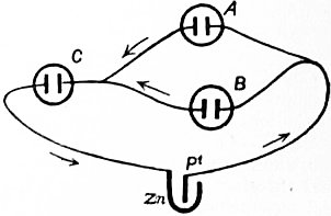
Fig. 1.
Faraday’s Laws.—The first exact quantitative study of electrolytic phenomena was made about 1830 by Michael Faraday (Experimental Researches, 1833). When an electric current flows round a circuit, there is no accumulation of electricity anywhere in the circuit, hence the current strength is everywhere the same, and we may picture the current as analogous to the flow of an incompressible fluid. Acting on this view, Faraday set himself to examine the relation between the flow of electricity round the circuit and the amount of chemical decomposition. He passed the current driven by a voltaic battery ZnPt (fig. 1) through two branches containing the two electrolytic cells A and B. The reunited current was then led through another cell C, in which the strength of the current must be the sum of those in the arms A and B. Faraday found that the mass of substance liberated at the electrodes in the cell C was equal to the sum of the masses liberated in the cells A and B. He also found that, for the same current, the amount of chemical action was independent of the size of the electrodes and proportional to the time that the current flowed. Regarding the current as the passage of a certain amount of electricity per second, it will be seen that the results of all these experiments may be summed up in the statement that the amount of chemical action is proportional to the quantity of electricity which passes through the cell.
Faraday’s next step was to pass the same current through different electrolytes in series. He found that the amounts of the substances liberated in each cell were proportional to the chemical equivalent weights of those substances. Thus, if the current be passed through dilute sulphuric acid between hydrogen electrodes, and through a solution of copper sulphate, it will be found that the mass of hydrogen evolved in the first cell is to the mass of copper deposited in the second as 1 is to 31.8. Now this ratio is the same as that which gives the relative chemical equivalents of hydrogen and copper, for 1 gramme of hydrogen and 31.8 grammes of copper unite chemically with the same weight of any acid radicle such as chlorine or the sulphuric group, SO4. Faraday examined also the electrolysis of certain fused salts such as lead chloride and silver chloride. Similar relations were found to hold and the amounts of chemical change to be the same for the same electric transfer as in the case of solutions.
We may sum up the chief results of Faraday’s work in the statements known as Faraday’s laws: The mass of substance liberated from an electrolyte by the passage of a current is proportional (1) to the total quantity of electricity which passes through the electrolyte, and (2) to the chemical equivalent weight of the substance liberated.
Since Faraday’s time his laws have been confirmed by modern research, and in favourable cases have been shown to hold good with an accuracy of at least one part in a thousand. The principal object of this more recent research has been the determination of the quantitative amount of chemical change associated with the passage for a given time of a current of strength known in electromagnetic units. It is found that the most accurate and convenient apparatus to use is a platinum bowl filled with a solution of silver nitrate containing about fifteen parts of the salt to one hundred of water. Into the solution dips a silver plate wrapped in filter paper, and the current is passed from the silver plate as anode to the bowl as cathode. The bowl is weighed before and after the passage of the current, and the increase gives the mass of silver deposited. The mean result of the best determinations shows that when a current of one ampere is passed for one second, a mass of silver is deposited equal to 0.001118 gramme. So accurate and convenient is this determination that it is now used conversely as a practical definition of the ampere, which (defined theoretically in terms of magnetic force) is defined practically as the current which in one second deposits 1.118 milligramme of silver.
Taking the chemical equivalent weight of silver, as determined by chemical experiments, to be 107.92, the result described gives as the electrochemical equivalent of an ion of unit chemical equivalent the value 1.036 × 10⁻⁵. If, as is now usual, we take the equivalent weight of oxygen as our standard and call it 16, the equivalent weight of hydrogen is 1.008, and its electrochemical equivalent is 1.044 × 10⁻⁵. The electrochemical equivalent of any other substance, whether element or compound, may be found by multiplying its chemical equivalent by 1.036 × 10⁻⁵. If, instead of the ampere, we take the C.G.S. electromagnetic unit of current, this number becomes 1.036 × 10⁻⁴.
Chemical Nature of the Ions.—A study of the products of decomposition does not necessarily lead directly to a knowledge of the ions actually employed in carrying the current through the electrolyte. Since the electric forces are active throughout the whole solution, all the ions must come under its influence and therefore move, but their separation from the electrodes is determined by the electromotive force needed to liberate them. Thus, as long as every ion of the solution is present in the layer of liquid next the electrode, the one which responds to the least electromotive force will alone be set free. When the amount of this ion in the surface layer becomes too small to carry all the current across the junction, other ions must also be used, and either they or their secondary products will appear also at the electrode. In aqueous solutions, for instance, a few hydrogen (H) and hydroxyl (OH) ions derived from the water are always present, and will be liberated if the other ions require a higher decomposition voltage and the current be kept so small that hydrogen and hydroxyl ions can be formed fast enough to carry all the current across the junction between solution and electrode.
The issue is also obscured in another way. When the ions are set free at the electrodes, they may unite with the substance of the electrode or with some constituent of the solution to form secondary products. Thus the hydroxyl mentioned above decomposes into water and oxygen, and the chlorine produced by the electrolysis of a chloride may attack the metal of the anode. This leads us to examine more closely the part played by water in the electrolysis of aqueous solutions. Distilled water is a very bad conductor, though, even when great care is taken to remove all dissolved bodies, there is evidence to show that some part of the trace of conductivity remaining is due to the water itself. By careful redistillation F. Kohlrausch has prepared water of which the conductivity compared with that of mercury was only 0.40 × 10⁻¹¹ at 18° C. Even here some little impurity was present, and the conductivity of chemically pure water was estimated by thermodynamic reasoning as 0.36 × 10⁻¹¹ at 18° C. As we shall see later, the conductivity of very dilute salt solutions is proportional to the concentration, so that it is probable that, in most cases, practically all the current is carried by the salt. At the electrodes, however, the small quantity of hydrogen and hydroxyl ions from the water are liberated first in cases where the ions of the salt have a higher decomposition voltage. The water being present in excess, the hydrogen and hydroxyl are re-formed at once and therefore are set free continuously. If the current be so strong that new hydrogen and hydroxyl ions cannot be formed in time, other substances are liberated; in a solution of sulphuric acid a strong current will evolve sulphur dioxide, the more readily as the concentration of the solution is increased. Similar phenomena are seen in the case of a solution of hydrochloric acid. When the solution is weak, hydrogen and oxygen are evolved; but, as the concentration is increased, and the current raised, more and more chlorine is liberated.
An interesting example of secondary action is shown by the common technical process of electroplating with silver from a bath of potassium silver cyanide. Here the ions are potassium and the group Ag(CN)2.1 Each potassium ion as it reaches the cathode precipitates silver by reacting with the solution in accordance with the chemical equation
K + KAg(CN)2 = 2KCN + Ag,
while the anion Ag(CN)2 dissolves an atom of silver from the anode, and re-forms the complex cyanide KAg(CN)2 by combining with the 2KCN produced in the reaction described in the equation. If the anode consist of platinum, cyanogen gas is evolved thereat from the anion Ag(CN)2, and the platinum becomes covered with the insoluble silver cyanide, AgCN, which soon stops the current. The coating of silver obtained by this process is coherent and homogeneous, while that deposited from a solution of silver nitrate, as the result of the primary action of the current, is crystalline and easily detached.
In the electrolysis of a concentrated solution of sodium acetate, hydrogen is evolved at the cathode and a mixture of ethane and carbon dioxide at the anode. According to H. Jahn,2 the processes at the anode can be represented by the equations
2CH3·COO + H2O = 2CH3·COOH + O 2CH3·COOH + O = C2H6 + 2CO2 + H2O.
The hydrogen at the cathode is developed by the secondary action
2Na + 2H2O = 2NaOH + H2.
Many organic compounds can be prepared by taking advantage of secondary actions at the electrodes, such as reduction by the cathodic hydrogen, or oxidation at the anode (see Electrochemistry).
It is possible to distinguish between double salts and salts of compound acids. Thus J.W. Hittorf showed that when a current was passed through a solution of sodium platino-chloride, the platinum appeared at the anode. The salt must therefore be derived from an acid, chloroplatinic acid, H2PtCl6, and have the formula Na2PtCl6, the ions being Na and PtCl6”, for if it were a double salt it would decompose as a mixture of sodium chloride and platinum chloride and both metals would go to the cathode.
Early Theories of Electrolysis.—The obvious phenomena to be explained by any theory of electrolysis are the liberation of the products of chemical decomposition at the two electrodes while the intervening liquid is unaltered. To explain these facts, Theodor Grotthus (1785-1822) in 1806 put forward an hypothesis which supposed that the opposite chemical constituents of an electrolyte interchanged partners all along the line between the electrodes when a current passed. Thus, if the molecule of a substance in solution is represented by AB, Grotthus considered a chain of AB molecules to exist from one electrode to the other. Under the influence of an applied electric force, he imagined that the B part of the first molecule was liberated at the anode, and that the A part thus isolated united with the B part of the second molecule, which, in its turn, passed on its A to the B of the third molecule. In this manner, the B part of the last molecule of the chain was seized by the A of the last molecule but one, and the A part of the last molecule liberated at the surface of the cathode.
Chemical phenomena throw further light on this question. If two solutions containing the salts AB and CD be mixed, double decomposition is found to occur, the salts AD and CB being formed till a certain part of the first pair of substances is transformed into an equivalent amount of the second pair. The proportions between the four salts AB, CD, AD and CB, which exist finally in solution, are found to be the same whether we begin with the pair AB and CD or with the pair AD and CB. To explain this result, chemists suppose that both changes can occur simultaneously, and that equilibrium results when the rate at which AB and CD are transformed into AD and CB is the same as the rate at which the reverse change goes on. A freedom of interchange is thus indicated between the opposite parts of the molecules of salts in solution, and it follows reasonably that with the solution of a single salt, say sodium chloride, continual interchanges go on between the sodium and chlorine parts of the different molecules.
These views were applied to the theory of electrolysis by R.J.E. Clausius. He pointed out that it followed that the electric forces did not cause the interchanges between the opposite parts of the dissolved molecules but only controlled their direction. Interchanges must be supposed to go on whether a current passes or not, the function of the electric forces in electrolysis being merely to determine in what direction the parts of the molecules shall work their way through the liquid and to effect actual separation of these parts (or their secondary products) at the electrodes. This conclusion is supported also by the evidence supplied by the phenomena of electrolytic conduction (see Conduction, Electric, § II.). If we eliminate the reverse electromotive forces of polarization at the two electrodes, the conduction of electricity through electrolytes is found to conform to Ohm’s law; that is, once the polarization is overcome, the current is proportional to the electromotive force applied to the bulk of the liquid. Hence there can be no reverse forces of polarization inside the liquid itself, such forces being confined to the surface of the electrodes. No work is done in separating the parts of the molecules from each other. This result again indicates that the parts of the molecules are effectively separate from each other, the function of the electric forces being merely directive.
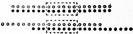
Fig. 2.
Migration of the Ions.—The opposite parts of an electrolyte, which work their way through the liquid under the action of the electric forces, were named by Faraday the ions—the travellers. The changes of concentration which occur in the solution near the two electrodes were referred by W. Hittorf (1853) to the unequal speeds with which he supposed the two opposite ions to travel. It is clear that, when two opposite streams of ions move past each other, equivalent quantities are liberated at the two ends of the system. If the ions move at equal rates, the salt which is decomposed to supply the ions liberated must be taken equally from the neighbourhood of the two electrodes. But if one ion, say the anion, travels faster through the liquid than the other, the end of the solution from which it comes will be more exhausted of salt than the end towards which it goes. If we assume that no other cause is at work, it is easy to prove that, with non-dissolvable electrodes, the ratio of salt lost at the anode to the salt lost at the cathode must be equal to the ratio of the velocity of the cation to the velocity of the anion. This result may be illustrated by fig. 2. The black circles represent one ion and the white circles the other. If the black ions move twice as fast as the white ones, the state of things after the passage of a current will be represented by the lower part of the figure. Here the middle part of the solution is unaltered and the number of ions liberated is the same at either end, but the amount of salt left at one end is less than that at the other. On the right, towards which the faster ion travels, five molecules of salt are left, being a loss of two from the original seven. On the left, towards which the slower ion moves, only three molecules remain—a loss of four. Thus, the ratio of the losses at the two ends is two to one—the same as the ratio of the assumed ionic velocities. It should be noted, however, that another cause would be competent to explain the unequal dilution of the two solutions. If either ion carried with it some of the unaltered salt or some of the solvent, concentration or dilution of the liquid would be produced where the ion was liberated. There is reason to believe that in certain cases such complex ions do exist, and interfere with the results of the differing ionic velocities.
Hittorf and many other observers have made experiments to determine the unequal dilution of a solution round the two electrodes when a current passes. Various forms of apparatus have been used, the principle of them all being to secure efficient separation of the two volumes of solution in which the changes occur. In some cases porous diaphragms have been employed; but such diaphragms introduce a new complication, for the liquid as a whole is pushed through them by the action of the current, the phenomenon being known as electric endosmose. Hence experiments without separating diaphragms are to be preferred, and the apparatus may be considered effective when a considerable bulk of intervening solution is left unaltered in composition. It is usual to express the results in terms of what is called the migration constant of the anion, that is, the ratio of the amount of salt lost by the anode vessel to the whole amount lost by both vessels. Thus the statement that the migration constant or transport number for a decinormal solution of copper sulphate is 0.632 implies that of every gramme of copper sulphate lost by a solution containing originally one-tenth of a gramme equivalent per litre when a current is passed through it between platinum electrodes, 0.632 gramme is taken from the cathode vessel and 0.368 gramme from the anode vessel. For certain concentrated solutions the transport number is found to be greater than unity; thus for a normal solution of cadmium iodide its value is 1.12. On the theory that the phenomena are wholly due to unequal ionic velocities this result would mean that the cation like the anion moved against the conventional direction of the current. That a body carrying a positive electric charge should move against the direction of the electric intensity is contrary to all our notions of electric forces, and we are compelled to seek some other explanation. An alternative hypothesis is given by the idea of complex ions. If some of the anions, instead of being simple iodine ions represented chemically by the symbol I, are complex structures formed by the union of iodine with unaltered cadmium iodide—structures represented by some such chemical formula as I(CdI2), the concentration of the solution round the anode would be increased by the passage of an electric current, and the phenomena observed would be explained. It is found that, in such cases as this, where it seems necessary to imagine the existence of complex ions, the transport number changes rapidly as the concentration of the original solution is changed. Thus, diminishing the concentration of the cadmium iodine solution from normal to one-twentieth normal changes the transport number from 1.12 to 0.64. Hence it is probable that in cases where the transport number keeps constant with changing concentration the hypothesis of complex ions is unnecessary, and we may suppose that the transport number is a true migration constant from which the relative velocities of the two ions may be calculated in the matter suggested by Hittorf and illustrated in fig. 2. This conclusion is confirmed by the results of the direct visual determination of ionic velocities (see Conduction, Electric, § II.), which, in cases where the transport number remains constant, agree with the values calculated from those numbers. Many solutions in which the transport numbers vary at high concentration often become simple at greater dilution. For instance, to take the two solutions to which we have already referred, we have—
Concentration 2.0 1.5 1.0 0.5 0.2 0.1 0.05 0.02 0.01 normal
Copper sulphate transport numbers 0.72 0.714 0.696 0.668 0.643 0.632 0.626 0.62 · ·
Cadmium iodide ” ” 1.22 1.18 1.12 1.00 0.83 0.71 0.64 0.59 0.56
It is probable that in both these solutions complex ions exist at fairly high concentrations, but gradually gets less in number and finally disappear as the dilution is increased. In such salts as potassium chloride the ions seem to be simple throughout a wide range of concentration since the transport numbers for the same series of concentrations as those used above run—
Potassium chloride— 0.515, 0.515, 0.514, 0.513, 0.509, 0.508, 0.507, 0.507, 0.506.
The next important step in the theory of the subject was made by F. Kohlrausch in 1879. Kohlrausch formulated a theory of electrolytic conduction based on the idea that, under the action of the electric forces, the oppositely charged ions moved in opposite directions through the liquid, carrying their charges with them. If we eliminate the polarization at the electrodes, it can be shown that an electrolyte possesses a definite electric resistance and therefore a definite conductivity. The conductivity gives us the amount of electricity conveyed per second under a definite electromotive force. On the view of the process of conduction described above, the amount of electricity conveyed per second is measured by the product of the number of ions, known from the concentration of the solution, the charge carried by each of them, and the velocity with which, on the average, they move through the liquid. The concentration is known, and the conductivity can be measured experimentally; thus the average velocity with which the ions move past each other under the existent electromotive force can be estimated. The velocity with which the ions move past each other is equal to the sum of their individual velocities, which can therefore be calculated. Now Hittorf’s transport number, in the case of simple salts in moderately dilute solution, gives us the ratio between the two ionic velocities. Hence the absolute velocities of the two ions can be determined, and we can calculate the actual speed with which a certain ion moves through a given liquid under the action of a given potential gradient or electromotive force. The details of the calculation are given in the article Conduction, Electric, § II., where also will be found an account of the methods which have been used to measure the velocities of many ions by direct visual observation. The results go to show that, where the existence of complex ions is not indicated by varying transport numbers, the observed velocities agree with those calculated on Kohlrausch’s theory.
Dissociation Theory.—The verification of Kohlrausch’s theory of ionic velocity verifies also the view of electrolysis which regards the electric current as due to streams of ions moving in opposite directions through the liquid and carrying their opposite electric charges with them. There remains the question how the necessary migratory freedom of the ions is secured. As we have seen, Grotthus imagined that it was the electric forces which sheared the ions past each other and loosened the chemical bonds holding the opposite parts of each dissolved molecule together. Clausius extended to electrolysis the chemical ideas which looked on the opposite parts of the molecule as always changing partners independently of any electric force, and regarded the function of the current as merely directive. Still, the necessary freedom was supposed to be secured by interchanges of ions between molecules at the instants of molecular collision only; during the rest of the life of the ions they were regarded as linked to each other to form electrically neutral molecules.
In 1887 Svante Arrhenius, professor of physics at Stockholm, put forward a new theory which supposed that the freedom of the opposite ions from each other was not a mere momentary freedom at the instants of molecular collision, but a more or less permanent freedom, the ions moving independently of each other through the liquid. The evidence which led Arrhenius to this conclusion was based on van ‘t Hoff’s work on the osmotic pressure of solutions (see Solution). If a solution, let us say of sugar, be confined in a closed vessel through the walls of which the solvent can pass but the solution cannot, the solvent will enter till a certain equilibrium pressure is reached. This equilibrium pressure is called the osmotic pressure of the solution, and thermodynamic theory shows that, in an ideal case of perfect separation between solvent and solute, it should have the same value as the pressure which a number of molecules equal to the number of solute molecules in the solution would exert if they could exist as a gas in a space equal to the volume of the solution, provided that the space was large enough (i.e. the solution dilute enough) for the intermolecular forces between the dissolved particles to be inappreciable. Van ‘t Hoff pointed out that measurements of osmotic pressure confirmed this value in the case of dilute solutions of cane sugar.
Thermodynamic theory also indicates a connexion between the osmotic pressure of a solution and the depression of its freezing point and its vapour pressure compared with those of the pure solvent. The freezing points and vapour pressures of solutions of sugar are also in conformity with the theoretical numbers. But when we pass to solutions of mineral salts and acids—to solutions of electrolytes in fact—we find that the observed values of the osmotic pressures and of the allied phenomena are greater than the normal values. Arrhenius pointed out that these exceptions would be brought into line if the ions of electrolytes were imagined to be separate entities each capable of producing its own pressure effects just as would an ordinary dissolved molecule.
Two relations are suggested by Arrhenius’ theory. (1) In very dilute solutions of simple substances, where only one kind of dissociation is possible and the dissociation of the ions is complete, the number of pressure-producing particles necessary to produce the observed osmotic effects should be equal to the number of ions given by a molecule of the salt as shown by its electrical properties. Thus the osmotic pressure, or the depression of the freezing point of a solution of potassium chloride should, at extreme dilution, be twice the normal value, but of a solution of sulphuric acid three times that value, since the potassium salt contains two ions and the acid three. (2) As the concentration of the solutions increases, the ionization as measured electrically and the dissociation as measured osmotically might decrease more or less together, though, since the thermodynamic theory only holds when the solution is so dilute that the dissolved particles are beyond each other’s sphere of action, there is much doubt whether this second relation is valid through any appreciable range of concentration.
At present, measurements of freezing point are more convenient and accurate than those of osmotic pressure, and we may test the validity of Arrhenius’ relations by their means. The theoretical value for the depression of the freezing point of a dilute solution per gramme-equivalent of solute per litre is 1.857° C. Completely ionized solutions of salts with two ions should give double this number or 3.714°, while electrolytes with three ions should have a value of 5.57°.
The following results are given by H.B. Loomis for the concentration of 0.01 gramme-molecule of salt to one thousand grammes of water. The salts tabulated are those of which the equivalent conductivity reaches a limiting value indicating that complete ionization is reached as dilution is increased. With such salts alone is a valid comparison possible.
Molecular Depressions of the Freezing Point.
Electrolytes with two Ions.
Potassium chloride 3.60 Nitric acid 3.73
Sodium chloride 3.67 Potassium nitrate 3.46
Potassium hydrate 3.71 Sodium nitrate 3.55
Hydrochloric acid 3.61 Ammonium nitrate 3.58
Electrolytes with three Ions.
Sulphuric acid 4.49 Calcium chloride 5.04
Sodium sulphate 5.09 Magnesium chloride 5.08
At the concentration used by Loomis the electrical conductivity indicates that the ionization is not complete, particularly in the case of the salts with divalent ions in the second list. Allowing for incomplete ionization the general concordance of these numbers with the theoretical ones is very striking.
The measurements of freezing points of solutions at the extreme dilution necessary to secure complete ionization is a matter of great difficulty, and has been overcome only in a research initiated by E.H. Griffiths.3 Results have been obtained for solutions of sugar, where the experimental number is 1.858, and for potassium chloride, which gives a depression of 3.720. These numbers agree with those indicated by theory, viz. 1.857 and 3.714, with astonishing exactitude. We may take Arrhenius’ first relation as established for the case of potassium chloride.
The second relation, as we have seen, is not a strict consequence of theory, and experiments to examine it must be treated as an investigation of the limits within which solutions are dilute within the thermodynamic sense of the word, rather than as a test of the soundness of the theory. It is found that divergence has begun before the concentration has become great enough to enable freezing points to be measured with any ordinary apparatus. The freezing point curve usually lies below the electrical one, but approaches it as dilution is increased.4
Returning once more to the consideration of the first relation, which deals with the comparison between the number of ions and the number of pressure-producing particles in dilute solution, one caution is necessary. In simple substances like potassium chloride it seems evident that one kind of dissociation only is possible. The electrical phenomena show that there are two ions to the molecule, and that these ions are electrically charged. Corresponding with this result we find that the freezing point of dilute solutions indicates that two pressure-producing particles per molecule are present. But the converse relation does not necessarily follow. It would be possible for a body in solution to be dissociated into non-electrical parts, which would give osmotic pressure effects twice or three times the normal value, but, being uncharged, would not act as ions and impart electrical conductivity to the solution. L. Kahlenberg (Jour. Phys. Chem., 1901, v. 344, 1902, vi. 43) has found that solutions of diphenylamine in methyl cyanide possess an excess of pressure-producing particles and yet are non-conductors of electricity. It is possible that in complicated organic substances we might have two kinds of dissociation, electrical and non-electrical, occurring simultaneously, while the possibility of the association of molecules accompanied by the electrical dissociation of some of them into new parts should not be overlooked. It should be pointed out that no measurements on osmotic pressures or freezing points can do more than tell us that an excess of particles is present; such experiments can throw no light on the question whether or not those particles are electrically charged. That question can only be answered by examining whether or not the particles move in an electric field.
The dissociation theory was originally suggested by the osmotic pressure relations. But not only has it explained satisfactorily the electrical properties of solutions, but it seems to be the only known hypothesis which is consistent with the experimental relation between the concentration of a solution and its electrical conductivity (see Conduction, Electric, § II., “Nature of Electrolytes”). It is probable that the electrical effects constitute the strongest arguments in favour of the theory. It is necessary to point out that the dissociated ions of such a body as potassium chloride are not in the same condition as potassium and chlorine in the free state. The ions are associated with very large electric charges, and, whatever their exact relations with those charges may be, it is certain that the energy of a system in such a state must be different from its energy when unelectrified. It is not unlikely, therefore, that even a compound as stable in the solid form as potassium chloride should be thus dissociated when dissolved. Again, water, the best electrolytic solvent known, is also the body of the highest specific inductive capacity (dielectric constant), and this property, to whatever cause it may be due, will reduce the forces between electric charges in the neighbourhood, and may therefore enable two ions to separate.
This view of the nature of electrolytic solutions at once explains many well-known phenomena. Other physical properties of these solutions, such as density, colour, optical rotatory power, &c., like the conductivities, are additive, i.e. can be calculated by adding together the corresponding properties of the parts. This again suggests that these parts are independent of each other. For instance, the colour of a salt solution is the colour obtained by the superposition of the colours of the ions and the colour of any undissociated salt that may be present. All copper salts in dilute solution are blue, which is therefore the colour of the copper ion. Solid copper chloride is brown or yellow, so that its concentrated solution, which contains both ions and undissociated molecules, is green, but changes to blue as water is added and the ionization becomes complete. A series of equivalent solutions all containing the same coloured ion have absorption spectra which, when photographed, show identical absorption bands of equal intensity.5 The colour changes shown by many substances which are used as indicators (q.v.) of acids or alkalis can be explained in a similar way. Thus para-nitrophenol has colourless molecules, but an intensely yellow negative ion. In neutral, and still more in acid solutions, the dissociation of the indicator is practically nothing, and the liquid is colourless. If an alkali is added, however, a highly dissociated salt of para-nitrophenol is formed, and the yellow colour is at once evident. In other cases, such as that of litmus, both the ion and the undissociated molecule are coloured, but in different ways.
Electrolytes possess the power of coagulating solutions of colloids such as albumen and arsenious sulphide. The mean values of the relative coagulative powers of sulphates of mono-, di-, and tri-valent metals have been shown experimentally to be approximately in the ratios 1 : 35 : 1023. The dissociation theory refers this to the action of electric charges carried by the free ions. If a certain minimum charge must be collected in order to start coagulation, it will need the conjunction of 6n monovalent, or 3n divalent, to equal the effect of 2n tri-valent ions. The ratios of the coagulative powers can thus be calculated to be 1 : x : x², and putting x = 32 we get 1 : 32 : 1024, a satisfactory agreement with the numbers observed.6
The question of the application of the dissociation theory to the case of fused salts remains. While it seems clear that the conduction in this case is carried on by ions similar to those of solutions, since Faraday’s laws apply equally to both, it does not follow necessarily that semi-permanent dissociation is the only way to explain the phenomena. The evidence in favour of dissociation in the case of solutions does not apply to fused salts, and it is possible that, in their case, a series of molecular interchanges, somewhat like Grotthus’s chain, may represent the mechanism of conduction.
An interesting relation appears when the electrolytic conductivity of solutions is compared with their chemical activity. The readiness and speed with which electrolytes react are in sharp contrast with the difficulty experienced in the case of non-electrolytes. Moreover, a study of the chemical relations of electrolytes indicates that it is always the electrolytic ions that are concerned in their reactions. The tests for a salt, potassium nitrate, for example, are the tests not for KNO3, but for its ions K and NO3, and in cases of double decomposition it is always these ions that are exchanged for those of other substances. If an element be present in a compound otherwise than as an ion, it is not interchangeable, and cannot be recognized by the usual tests. Thus neither a chlorate, which contains the ion ClO3, nor monochloracetic acid, shows the reactions of chlorine, though it is, of course, present in both substances; again, the sulphates do not answer to the usual tests which indicate the presence of sulphur as sulphide. The chemical activity of a substance is a quantity which may be measured by different methods. For some substances it has been shown to be independent of the particular reaction used. It is then possible to assign to each body a specific coefficient of affinity. Arrhenius has pointed out that the coefficient of affinity of an acid is proportional to its electrolytic ionization.