VOLUME IX SLICE II Ehud to Electroscope (continued 6)
Reading edition
Maxwell’s Researches.—James Clerk Maxwell (1831-1879) entered on his electrical studies with a desire to ascertain if the ideas of Faraday, so different from those of Poisson and the French mathematicians, could be made the foundation of a mathematical method and brought under the power of analysis.14 Maxwell started with the conception that all electric and magnetic phenomena are due to effects taking place in the dielectric or in the ether if the space be vacuous. The phenomena of light had compelled physicists to postulate a space-filling medium, to which the name ether had been given, and Henry and Faraday had long previously suggested the idea of an electromagnetic medium. The vibrations of this medium constitute the agency called light. Maxwell saw that it was unphilosophical to assume a multiplicity of ethers or media until it had been proved that one would not fulfil all the requirements. He formulated the conception, therefore, of electric charge as consisting in a displacement taking place in the dielectric or electromagnetic medium (see Electrostatics). Maxwell never committed himself to a precise definition of the physical nature of electric displacement, but considered it as defining that which Faraday had called the polarization in the insulator, or, what is equivalent, the number of lines of electrostatic force passing normally through a unit of area in the dielectric. A second fundamental conception of Maxwell was that the electric displacement whilst it is changing is in effect an electric current, and creates, therefore, magnetic force. The total current at any point in a dielectric must be considered as made up of two parts: first, the true conduction current, if it exists; and second, the rate of change of dielectric displacement. The fundamental fact connecting electric currents and magnetic fields is that the line integral of magnetic force taken once round a conductor conveying an electric current is equal to 4 π-times the surface integral of the current density, or to 4 π-times the total current flowing through the closed line round which the integral is taken (see Electrokinetics). A second relation connecting magnetic and electric force is based upon Faraday’s fundamental law of induction, that the rate of change of the total magnetic flux linked with a conductor is a measure of the electromotive force created in it (see Electrokinetics). Maxwell also introduced in this connexion the notion of the vector potential. Coupling together these ideas he was finally enabled to prove that the propagation of electric and magnetic force takes place through space with a certain velocity determined by the dielectric constant and the magnetic permeability of the medium. To take a simple instance, if we consider an electric current as flowing in a conductor it is, as Oersted discovered, surrounded by closed lines of magnetic force. If we imagine the current in the conductor to be instantaneously reversed in direction, the magnetic force surrounding it would not be instantly reversed everywhere in direction, but the reversal would be propagated outwards through space with a certain velocity which Maxwell showed was inversely as the square root of the product of the magnetic permeability and the dielectric constant or specific inductive capacity of the medium.
These great results were announced by him for the first time in a paper presented in 1864 to the Royal Society of London and printed in the Phil. Trans. for 1865, entitled “A Dynamical Theory of the Electromagnetic Field.” Maxwell showed in this paper that the velocity of propagation of an electromagnetic impulse through space could also be determined by certain experimental methods which consisted in measuring the same electric quantity, capacity, resistance or potential in two ways. W.E. Weber had already laid the foundations of the absolute system of electric and magnetic measurement, and proved that a quantity of electricity could be measured either by the force it exercises upon another static or stationary quantity of electricity, or magnetically by the force this quantity of electricity exercises upon a magnetic pole when flowing through a neighbouring conductor. The two systems of measurement were called respectively the electrostatic and the electromagnetic systems (see Units, Physical). Maxwell suggested new methods for the determination of this ratio of the electrostatic to the electromagnetic units, and by experiments of great ingenuity was able to show that this ratio, which is also that of the velocity of the propagation of an electromagnetic impulse through space, is identical with that of light. This great fact once ascertained, it became clear that the notion that electric phenomena are affections of the luminiferous ether was no longer a mere speculation but a scientific theory capable of verification. An immediate deduction from Maxwell’s theory was that in transparent dielectrics, the dielectric constant or specific inductive capacity should be numerically equal to the square of the refractive index for very long electric waves. At the time when Maxwell developed his theory the dielectric constants of only a few transparent insulators were known and these were for the most part measured with steady or unidirectional electromotive force. The only refractive indices which had been measured were the optical refractive indices of a number of transparent substances. Maxwell made a comparison between the optical refractive index and the dielectric constant of paraffin wax, and the approximation between the numerical values of the square of the first and that of the last was sufficient to show that there was a basis for further work. Maxwell’s electric and magnetic ideas were gathered together in a great mathematical treatise on electricity and magnetism which was published in 1873.15 This book stimulated in a most remarkable degree theoretical and practical research into the phenomena of electricity and magnetism. Experimental methods were devised for the further exact measurements of the electromagnetic velocity and numerous determinations of the dielectric constants of various solids, liquids and gases, and comparisons of these with the corresponding optical refractive indices were conducted. This early work indicated that whilst there were a number of cases in which the square of optical refractive index for long waves and the dielectric constant of the same substance were sufficiently close to afford an apparent confirmation of Maxwell’s theory, yet in other cases there were considerable divergencies. L. Boltzmann (1844-1907) made a large number of determinations for solids and for gases, and the dielectric constants of many solid and liquid substances were determined by N.N. Schiller (b. 1848), P.A. Silow (b. 1850), J. Hopkinson and others. The accumulating determinations of the numerical value of the electromagnetic velocity (v) from the earliest made by Lord Kelvin (Sir W. Thomson) with the aid of King and McKichan, or those of Clerk Maxwell, W.E. Ayrton and J. Perry, to more recent ones by J.J. Thomson, F. Himstedt, H.A. Rowland, E.B. Rosa, J.S.H. Pellat and H.A. Abraham, showed it to be very close to the best determinations of the velocity of light (see Units, Physical). On the other hand, the divergence in some cases between the square of the optical refractive index and the dielectric constant was very marked. Hence although Maxwell’s theory of electrical action when first propounded found many adherents in Great Britain, it did not so much dominate opinion on the continent of Europe.
Fourth Period.—With the publication of Clerk Maxwell’s treatise in 1873, we enter fully upon the fourth and modern period of electrical research. On the technical side the invention of a new form of armature for dynamo electric machines by Z.T. Gramme (1826-1901) inaugurated a departure from which we may date modern electrical engineering. It will be convenient to deal with technical development first.
Technical Development.—As far back as 1841 large magneto-electric machines driven by steam power had been constructed, and in 1856 F.H. Holmes had made a magneto machine with multiple permanent magnets which was installed in 1862 in Dungeness lighthouse. Further progress was made in 1867 when H. Wilde introduced the use of electromagnets for the field magnets. In 1860 Dr Antonio Pacinotti invented what is now called the toothed ring winding for armatures and described it in an Italian journal, but it attracted little notice until reinvented in 1870 by Gramme. In this new form of bobbin, the armature consisted of a ring of iron wire wound over with an endless coil of wire and connected to a commutator consisting of copper bars insulated from one another. Gramme dynamos were then soon made on the self-exciting principle. In 1873 at Vienna the fact was discovered that a dynamo machine of the Gramme type could also act as an electric motor and was set in rotation when a current was passed into it from another similar machine. Henceforth the electric transmission of power came within the possibilities of engineering.
Electric Lighting.—In 1876, Paul Jablochkov (1847-1894), a Russian officer, passing through Paris, invented his famous electric candle, consisting of two rods of carbon placed side by side and separated from one another by an insulating material. This invention in conjunction with an alternating current dynamo provided a new and simple form of electric arc lighting. Two years afterwards C.F. Brush, in the United States, produced another efficient form of dynamo and electric arc lamp suitable for working in series (see Lighting: Electric), and these inventions of Brush and Jablochkov inaugurated commercial arc lighting. The so-called subdivision of electric light by incandescent lighting lamps then engaged attention. E.A. King in 1845 and W.E. Staite in 1848 had made incandescent electric lamps of an elementary form, and T.A. Edison in 1878 again attacked the problem of producing light by the incandescence of platinum. It had by that time become clear that the most suitable material for an incandescent lamp was carbon contained in a good vacuum, and St G. Lane Fox and Sir J.W. Swan in England, and T.A. Edison in the United States, were engaged in struggling with the difficulties of producing a suitable carbon incandescence electric lamp. Edison constructed in 1879 a successful lamp of this type consisting of a vessel wholly of glass containing a carbon filament made by carbonizing paper or some other carbonizable material, the vessel being exhausted and the current led into the filament through platinum wires. In 1879 and 1880, Edison in the United States, and Swan in conjunction with C.H. Stearn in England, succeeded in completely solving the practical problems. From and after that date incandescent electric lighting became commercially possible, and was brought to public notice chiefly by an electrical exhibition held at the Crystal Palace, near London, in 1882. Edison, moreover, as well as Lane-Fox, had realized the idea of a public electric supply station, and the former proceeded to establish in Pearl Street, New York, in 1881, the first public electric supply station. A similar station in England was opened in the basement of a house in Holborn Viaduct, London, in March 1882. Edison, with copious ingenuity, devised electric meters, electric mains, lamp fittings and generators complete for the purpose. In 1881 C.A. Faure made an important improvement in the lead secondary battery which G. Planté (1834-1889) had invented in 1859, and storage batteries then began to be developed as commercial appliances by Faure, Swan, J.S. Sellon and many others (see Accumulator). In 1882, numerous electric lighting companies were formed for the conduct of public and private lighting, but an electric lighting act passed in that year greatly hindered commercial progress in Great Britain. Nevertheless the delay was utilized in the completion of inventions necessary for the safe and economical distribution of electric current for the purpose of electric lighting.
Telephone.—Going back a few years we find the technical applications of electrical invention had developed themselves in other directions. Alexander Graham Bell in 1876 invented the speaking telephone (q.v.), and Edison and Elisha Gray in the United States followed almost immediately with other telephonic inventions for electrically transmitting speech. About the same time D.E. Hughes in England invented the microphone. In 1879 telephone exchanges began to be developed in the United States, Great Britain and other countries.
Electric Power.—Following on the discovery in 1873 of the reversible action of the dynamo and its use as a motor, efforts began to be made to apply this knowledge to transmission of power, and S.D. Field, T.A. Edison, Leo Daft, E.M. Bentley and W.H. Knight, F.J. Sprague, C.J. Van Depoele and others between 1880 and 1884 were the pioneers of electric traction. One of the earliest electric tram cars was exhibited by E.W. and W. Siemens in Paris in 1881. In 1883 Lucien Gaulard, following a line of thought opened by Jablochkov, proposed to employ high pressure alternating currents for electric distributions over wide areas by means of transformers. His ideas were improved by Carl Zipernowsky and O.T. Bláthy in Hungary and by S.Z. de Ferranti in England, and the alternating current transformer (see Transformers) came into existence. Polyphase alternators were first exhibited at the Frankfort electrical exhibition in 1891, developed as a consequence of scientific researches by Galileo Ferraris (1847-1897), Nikola Tesla, M.O. von Dolivo-Dobrowolsky and C.E.L. Brown, and long distance transmission of electrical power by polyphase electrical currents (see Power Transmission: Electric) was exhibited in operation at Frankfort in 1891. Meanwhile the early continuous current dynamos devised by Gramme, Siemens and others had been vastly improved in scientific principle and practical construction by the labours of Siemens, J. Hopkinson, R.E.B. Crompton, Elihu Thomson, Rudolf Eickemeyer, Thomas Parker and others, and the theory of the action of the dynamo had been closely studied by J. and E. Hopkinson, G. Kapp, S.P. Thompson, C.P. Steinmetz and J. Swinburne, and great improvements made in the alternating current dynamo by W.M. Mordey, S.Z. de Ferranti and Messrs Ganz of Budapest. Thus in twenty years from the invention of the Gramme dynamo, electrical engineering had developed from small beginnings into a vast industry. The amendment, in 1888, of the Electric Lighting Act of 1882, before long caused a huge development of public electric lighting in Great Britain. By the end of the 19th century every large city in Europe and in North and South America was provided with a public electric supply for the purposes of electric lighting. The various improvements in electric illuminants, such as the Nernst oxide lamp, the tantalum and osmium incandescent lamps, and improved forms of arc lamp, enclosed, inverted and flame arcs, are described under Lighting: Electric.
Between 1890 and 1900, electric traction advanced rapidly in the United States of America but more slowly in England. In 1902 the success of deep tube electric railways in Great Britain was assured, and in 1904 main line railways began to abandon, at least experimentally, the steam locomotive and substitute for it the electric transmission of power. Long distance electrical transmission had been before that time exemplified in the great scheme of utilizing the falls of Niagara. The first projects were discussed in 1891 and 1892 and completed practically some ten years later. In this scheme large turbines were placed at the bottom of hydraulic fall tubes 150 ft. deep, the turbines being coupled by long shafts with 5000 H.P. alternating current dynamos on the surface. By these electric current was generated and transmitted to towns and factories around, being sent overhead as far as Buffalo, a distance of 18 m. At the end of the 19th century electrochemical industries began to be developed which depended on the possession of cheap electric energy. The production of aluminium in Switzerland and Scotland, carborundum and calcium carbide in the United States, and soda by the Castner-Kellner process, began to be conducted on an immense scale. The early work of Sir W. Siemens on the electric furnace was continued and greatly extended by Henri Moissan and others on its scientific side, and electrochemistry took its place as one of the most promising departments of technical research and invention. It was stimulated and assisted by improvements in the construction of large dynamos and increased knowledge concerning the control of powerful electric currents.
In the early part of the 20th century the distribution in bulk of electric energy for power purposes in Great Britain began to assume important proportions. It was seen to be uneconomical for each city and town to manufacture its own supply since, owing to the intermittent nature of the demand for current for lighting, the price had to be kept up to 4d. and 6d. per unit. It was found that by the manufacture in bulk, even by steam engines, at primary centres the cost could be considerably reduced, and in numerous districts in England large power stations began to be erected between 1903 and 1905 for the supply of current for power purposes. This involved almost a revolution in the nature of the tools used, and in the methods of working, and may ultimately even greatly affect the factory system and the concentration of population in large towns which was brought about in the early part of the 19th century by the invention of the steam engine.
Development of Electric Theory.
Turning now to the theory of electricity, we may note the equally remarkable progress made in 300 years in scientific insight into the nature of the agency which has so recast the face of human society. There is no need to dwell upon the early crude theories of the action of amber and lodestone. In a true scientific sense no hypothesis was possible, because few facts had been accumulated. The discoveries of Stephen Gray and C.F. de C. du Fay on the conductivity of some bodies for the electric agency and the dual character of electrification gave rise to the first notions of electricity as an imponderable fluid, or non-gravitative subtile matter, of a more refined and penetrating kind than ordinary liquids and gases. Its duplex character, and the fact that the electricity produced by rubbing glass and vitreous substances was different from that produced by rubbing sealing-wax and resinous substances, seemed to necessitate the assumption of two kinds of electric fluid; hence there arose the conception of positive and negative electricity, and the two-fluid theory came into existence.
Single-fluid Theory.—The study of the phenomena of the Leyden jar and of the fact that the inside and outside coatings possessed opposite electricities, so that in charging the jar as much positive electricity is added to one side as negative to the other, led Franklin about 1750 to suggest a modification called the single fluid theory, in which the two states of electrification were regarded as not the results of two entirely different fluids but of the addition or subtraction of one electric fluid from matter, so that positive electrification was to be looked upon as the result of increase or addition of something to ordinary matter and negative as a subtraction. The positive and negative electrifications of the two coatings of the Leyden jar were therefore to be regarded as the result of a transformation of something called electricity from one coating to the other, by which process a certain measurable quantity became so much less on one side by the same amount by which it became more on the other. A modification of this single fluid theory was put forward by F.U.T. Aepinus which was explained and illustrated in his Tentamen theoriae electricitatis et magnetismi, published in St Petersburg in 1759. This theory was founded on the following principles:—(1) the particles of the electric fluid repel each other with a force decreasing as the distance increases; (2) the particles of the electric fluid attract the atoms of all bodies and are attracted by them with a force obeying the same law; (3) the electric fluid exists in the pores of all bodies, and while it moves without any obstruction in conductors such as metals, water, &c., it moves with extreme difficulty in so-called non-conductors such as glass, resin, &c.; (4) electrical phenomena are produced either by the transference of the electric fluid of a body containing more to one containing less, or from its attraction and repulsion when no transference takes place. Electric attractions and repulsions were, however, regarded as differential actions in which the mutual repulsion of the particles of electricity operated, so to speak, in antagonism to the mutual attraction of particles of matter for one another and of particles of electricity for matter. Independently of Aepinus, Henry Cavendish put forward a single-fluid theory of electricity (Phil. Trans., 1771, 61, p. 584), in which he considered it in more precise detail.
Two-fluid Theory.—In the elucidation of electrical phenomena, however, towards the end of the 18th century, a modification of the two-fluid theory seems to have been generally preferred. The notion then formed of the nature of electrification was something as follows:—All bodies were assumed to contain a certain quantity of a so-called neutral fluid made up of equal quantities of positive and negative electricity, which when in this state of combination neutralized one another’s properties. The neutral fluid could, however, be divided up or separated into its two constituents, and these could be accumulated on separate conductors or non-conductors. This view followed from the discovery of the facts of electric induction of J. Canton (1753, 1754). When, for instance, a positively electrified body was found to induce upon another insulated conductor a charge of negative electricity on the side nearest to it, and a charge of positive electricity on the side farthest from it, this was explained by saying that the particles of each of the two electric fluids repelled one another but attracted those of the positive fluid. Hence the operation of the positive charge upon the neutral fluid was to draw towards the positive the negative constituent of the neutral charge and repel to the distant parts of the conductor the positive constituent.
C.A. Coulomb experimentally proved that the law of attraction and repulsion of simple electrified bodies was that the force between them varied inversely as the square of the distance and thus gave mathematical definiteness to the two-fluid hypothesis. It was then assumed that each of the two constituents of the neutral fluid had an atomic structure and that the so-called particles of one of the electric fluids, say positive, repelled similar particles with a force varying inversely as a square of the distance and attracted those of the opposite fluid according to the same law. This fact and hypothesis brought electrical phenomena within the domain of mathematical analysis and, as already mentioned, Laplace, Biot, Poisson, G.A.A. Plana (1781-1846), and later Robert Murphy (1806-1843), made them the subject of their investigations on the mode in which electricity distributes itself on conductors when in equilibrium.
Faraday’s Views.—The two-fluid theory may be said to have held the field until the time when Faraday began his researches on electricity. After he had educated himself by the study of the phenomena of lines of magnetic force in his discoveries on electromagnetic induction, he applied the same conception to electrostatic phenomena, and thus created the notion of lines of electrostatic force and of the important function of the dielectric or non-conductor in sustaining them. Faraday’s notion as to the nature of electrification, therefore, about the middle of the 19th century came to be something as follows:—He considered that the so-called charge of electricity on a conductor was in reality nothing on the conductor or in the conductor itself, but consisted in a state of strain or polarization, or a physical change of some kind in the particles of the dielectric surrounding the conductor, and that it was this physical state in the dielectric which constituted electrification. Since Faraday was well aware that even a good vacuum can act as a dielectric, he recognized that the state he called dielectric polarization could not be wholly dependent upon the presence of gravitative matter, but that there must be an electromagnetic medium of a supermaterial nature. In the 13th series of his Experimental Researches on Electricity he discussed the relation of a vacuum to electricity. Furthermore his electrochemical investigations, and particularly his discovery of the important law of electrolysis, that the movement of a certain quantity of electricity through an electrolyte is always accompanied by the transfer of a certain definite quantity of matter from one electrode to another and the liberation at these electrodes of an equivalent weight of the ions, gave foundation for the idea of a definite atomic charge of electricity. In fact, long previously to Faraday’s electrochemical researches, Sir H. Davy and J.J. Berzelius early in the 19th century had advanced the hypothesis that chemical combination was due to electric attractions between the electric charges carried by chemical atoms. The notion, however, that electricity is atomic in structure was definitely put forward by Hermann von Helmholtz in a well-known Faraday lecture. Helmholtz says: “If we accept the hypothesis that elementary substances are composed of atoms, we cannot well avoid concluding that electricity also is divided into elementary portions which behave like atoms of electricity.”16 Clerk Maxwell had already used in 1873 the phrase, “a molecule of electricity.”17 Towards the end of the third quarter of the 19th century it therefore became clear that electricity, whatever be its nature, was associated with atoms of matter in the form of exact multiples of an indivisible minimum electric charge which may be considered to be “Nature’s unit of electricity.” This ultimate unit of electric quantity Professor Johnstone Stoney called an electron.18 The formulation of electrical theory as far as regards operations in space free from matter was immensely assisted by Maxwell’s mathematical theory. Oliver Heaviside after 1880 rendered much assistance by reducing Maxwell’s mathematical analysis to more compact form and by introducing greater precision into terminology (see his Electrical Papers, 1892). This is perhaps the place to refer also to the great services of Lord Rayleigh to electrical science. Succeeding Maxwell as Cavendish professor of physics at Cambridge in 1880, he soon devoted himself especially to the exact redetermination of the practical electrical units in absolute measure. He followed up the early work of the British Association Committee on electrical units by a fresh determination of the ohm in absolute measure, and in conjunction with other work on the electrochemical equivalent of silver and the absolute electromotive force of the Clark cell may be said to have placed exact electrical measurement on a new basis. He also made great additions to the theory of alternating electric currents, and provided fresh appliances for other electrical measurements (see his Collected Scientific Papers, Cambridge, 1900).
Electro-optics.—For a long time Faraday’s observation on the rotation of the plane of polarized light by heavy glass in a magnetic field remained an isolated fact in electro-optics. Then M.E. Verdet (1824-1860) made a study of the subject and discovered that a solution of ferric perchloride in methyl alcohol rotated the plane of polarization in an opposite direction to heavy glass (Ann. Chim. Phys., 1854, 41, p. 370; 1855, 43, p. 37; Com. Rend., 1854, 39, p. 548). Later A.A.E.E. Kundt prepared metallic films of iron, nickel and cobalt, and obtained powerful negative optical rotation with them (Wied. Ann., 1884, 23, p. 228; 1886, 27, p. 191). John Kerr (1824-1907) discovered that a similar effect was produced when plane polarized light was reflected from the pole of a powerful magnet (Phil. Mag., 1877, [5], 3, p. 321, and 1878, 5, p. 161). Lord Kelvin showed that Faraday’s discovery demonstrated that some form of rotation was taking place along lines of magnetic force when passing through a medium.19 Many observers have given attention to the exact determination of Verdet’s constant of rotation for standard substances, e.g. Lord Rayleigh for carbon bisulphide,20 and Sir W.H. Perkin for an immense range of inorganic and organic bodies.21 Kerr also discovered that when certain homogeneous dielectrics were submitted to electric strain, they became birefringent (Phil. Mag., 1875, 50, pp. 337 and 446). The theory of electro-optics received great attention from Kelvin, Maxwell, Rayleigh, G.F. Fitzgerald, A. Righi and P.K.L. Drude, and experimental contributions from innumerable workers, such as F.T. Trouton, O.J. Lodge and J.L. Howard, and many others.
Electric Waves.—In the decade 1880-1890, the most important advance in electrical physics was, however, that which originated with the astonishing researches of Heinrich Rudolf Hertz (1857-1894). This illustrious investigator was stimulated, by a certain problem brought to his notice by H. von Helmholtz, to undertake investigations which had for their object a demonstration of the truth of Maxwell’s principle that a variation in electric displacement was in fact an electric current and had magnetic effects. It is impossible to describe here the details of these elaborate experiments; the reader must be referred to Hertz’s own papers, or the English translation of them by Prof. D.E. Jones. Hertz’s great discovery was an experimental realization of a suggestion made by G.F. Fitzgerald (1851-1901) in 1883 as to a method of producing electric waves in space. He invented for this purpose a radiator consisting of two metal rods placed in one line, their inner ends being provided with poles nearly touching and their outer ends with metal plates. Such an arrangement constitutes in effect a condenser, and when the two plates respectively are connected to the secondary terminals of an induction coil in operation, the plates are rapidly and alternately charged, and discharged across the spark gap with electrical oscillations (see Electrokinetics). Hertz then devised a wave detecting apparatus called a resonator. This in its simplest form consisted of a ring of wire nearly closed terminating in spark balls very close together, adjustable as to distance by a micrometer screw. He found that when the resonator was placed in certain positions with regard to the oscillator, small sparks were seen between the micrometer balls, and when the oscillator was placed at one end of a room having a sheet of zinc fixed against the wall at the other end, symmetrical positions could be found in the room at which, when the resonator was there placed, either no sparks or else very bright sparks occurred at the poles. These effects, as Hertz showed, indicated the establishment of stationary electric waves in space and the propagation of electric and magnetic force through space with a finite velocity. The other additional phenomena he observed finally contributed an all but conclusive proof of the truth of Maxwell’s views. By profoundly ingenious methods Hertz showed that these invisible electric waves could be reflected and refracted like waves of light by mirrors and prisms, and that familiar experiments in optics could be repeated with electric waves which could not affect the eye. Hence there arose a new science of electro-optics, and in all parts of Europe and the United States innumerable investigators took possession of the novel field of research with the greatest delight. O.J. Lodge,22 A. Righi,23 J.H. Poincaré,24 V.F.K. Bjerknes, P.K.L. Drude, J.J. Thomson,25 John Trowbridge, Max Abraham, and many others, contributed to its elucidation.
In 1892, E. Branly of Paris devised an appliance for detecting these waves which subsequently proved to be of immense importance. He discovered that they had the power of affecting the electric conductivity of materials when in a state of powder, the majority of metallic filings increasing in conductivity. Lodge devised a similar arrangement called a coherer, and E. Rutherford invented a magnetic detector depending on the power of electric oscillations to demagnetize iron or steel. The sum total of all these contributions to electrical knowledge had the effect of establishing Maxwell’s principles on a firm basis, but they also led to technical inventions of the very greatest utility. In 1896 G. Marconi applied a modified and improved form of Branly’s wave detector in conjunction with a novel form of radiator for the telegraphic transmission of intelligence through space without wires, and he and others developed this new form of telegraphy with the greatest rapidity and success into a startling and most useful means of communicating through space electrically without connecting wires.
Electrolysis.—The study of the transfer of electricity through liquids had meanwhile received much attention. The general facts and laws of electrolysis (q.v.) were determined experimentally by Davy and Faraday and confirmed by the researches of J.F. Daniell, R.W. Bunsen and Helmholtz. The modern theory of electrolysis grew up under the hands of R.J.E. Clausius, A.W. Williamson and F.W.G. Kohlrausch, and received a great impetus from the work of Svante Arrhenius, J.H. Van’t Hoff, W. Ostwald, H.W. Nernst and many others. The theory of the ionization of salts in solution has raised much discussion amongst chemists, but the general fact is certain that electricity only moves through liquids in association with matter, and simultaneously involves chemical dissociation of molecular groups.
Discharge through Gases.—Many eminent physicists had an instinctive feeling that the study of the passage of electricity through gases would shed much light on the intrinsic nature of electricity. Faraday devoted to a careful examination of the phenomena the XIIIth series of his Experimental Researches, and among the older workers in this field must be particularly mentioned J. Plücker, J.W. Hittorf, A.A. de la Rive, J.P. Gassiot, C.F. Varley, and W. Spottiswoode and J. Fletcher Moulton. It has long been known that air and other gases at the pressure of the atmosphere were very perfect insulators, but that when they were rarefied and contained in glass tubes with platinum electrodes sealed through the glass, electricity could be passed through them under sufficient electromotive force and produced a luminous appearance known as the electric glow discharge. The so-called vacuum tubes constructed by H. Geissler (1815-1879) containing air, carbonic acid, hydrogen, &c., under a pressure of one or two millimetres, exhibit beautiful appearances when traversed by the high tension current produced by the secondary circuit of an induction coil. Faraday discovered the existence of a dark space round the negative electrode which is usually known as the “Faraday dark space.” De la Rive added much to our knowledge of the subject, and J. Plücker and his disciple J.W. Hittorf examined the phenomena exhibited in so-called high vacua, that is, in exceedingly rarefied gases. C.F. Varley discovered the interesting fact that no current could be sent through the rarefied gas unless a certain minimum potential difference of the electrodes was excited. Sir William Crookes took up in 1872 the study of electric discharge through high vacua, having been led to it by his researches on the radiometer. The particular details of the phenomena observed will be found described in the article Conduction, Electric (§ III.). The main fact discovered by researches of Plücker, Hittorf and Crookes was that in a vacuum tube containing extremely rarefied air or other gas, a luminous discharge takes place from the negative electrode which proceeds in lines normal to the surface of the negative electrode and renders phosphorescent both the glass envelope and other objects placed in the vacuum tube when it falls upon them. Hittorf made in 1869 the discovery that solid objects could cast shadows or intercept this cathode discharge. The cathode discharge henceforth engaged the attention of many physicists. Varley had advanced tentatively the hypothesis that it consisted in an actual projection of electrified matter from the cathode, and Crookes was led by his researches in 1870, 1871 and 1872 to embrace and confirm this hypothesis in a modified form and announce the existence of a fourth state of matter, which he called radiant matter, demonstrating by many beautiful and convincing experiments that there was an actual projection of material substance of some kind possessing inertia from the surface of the cathode. German physicists such as E. Goldstein were inclined to take another view. Sir J.J. Thomson, the successor of Maxwell and Lord Rayleigh in the Cavendish chair of physics in the university of Cambridge, began about the year 1899 a remarkable series of investigations on the cathode discharge, which finally enabled him to make a measurement of the ratio of the electric charge to the mass of the particles of matter projected from the cathode, and to show that this electric charge was identical with the atomic electric charge carried by a hydrogen ion in the act of electrolysis, but that the mass of the cathode particles, or “corpuscles” as he called them, was far less, viz. about 1⁄2000th part of the mass of a hydrogen atom.26 The subject was pursued by Thomson and the Cambridge physicists with great mathematical and experimental ability, and finally the conclusion was reached that in a high vacuum tube the electric charge is carried by particles which have a mass only a fraction, as above mentioned, of that of the hydrogen atom, but which carry a charge equal to the unit electric charge of the hydrogen ion as found by electrochemical researches.27 P.E.A. Lenard made in 1894 (Wied. Ann. Phys., 51, p. 225) the discovery that these cathode particles or corpuscles could pass through a window of thin sheet aluminium placed in the wall of the vacuum tube and give rise to a class of radiation called the Lenard rays. W.C. Röntgen of Munich made in 1896 his remarkable discovery of the so-called X or Röntgen rays, a class of radiation produced by the impact of the cathode particles against an impervious metallic screen or anticathode placed in the vacuum tube. The study of Röntgen rays was ardently pursued by the principal physicists in Europe during the years 1897 and 1898 and subsequently. The principal property of these Röntgen rays which attracted public attention was their power of passing through many solid bodies and affecting a photographic plate. Hence some substances were opaque to them and others transparent. The astonishing feat of photographing the bones of the living animal within the tissues soon rendered the Röntgen rays indispensable in surgery and directed an army of investigators to their study.
Radioactivity.—One outcome of all this was the discovery by H. Becquerel in 1896 that minerals containing uranium, and particularly the mineral known as pitchblende, had the power of affecting sensitive photographic plates enclosed in a black paper envelope when the mineral was placed on the outside, as well as of discharging a charged electroscope (Com. Rend., 1896, 122, p. 420). This research opened a way of approach to the phenomena of radioactivity, and the history of the steps by which P. Curie and Madame Curie were finally led to the discovery of radium is one of the most fascinating chapters in the history of science. The study of radium and radioactivity (see Radioactivity) led before long to the further remarkable knowledge that these so-called radioactive materials project into surrounding space particles or corpuscles, some of which are identical with those projected from the cathode in a high vacuum tube, together with others of a different nature. The study of radioactivity was pursued with great ability not only by the Curies and A. Debierne, who associated himself with them, in France, but by E. Rutherford and F. Soddy in Canada, and by J.J. Thomson, Sir William Crookes, Sir William Ramsay and others in England.
Electronic Theory.—The final outcome of these investigations was the hypothesis that Thomson’s corpuscles or particles composing the cathode discharge in a high vacuum tube must be looked upon as the ultimate constituent of what we call negative electricity; in other words, they are atoms of negative electricity, possessing, however, inertia, and these negative electrons are components at any rate of the chemical atom. Each electron is a point-charge of negative electricity equal to 3.9 × 10⁻¹⁰ of an electrostatic unit or to 1.3 × 10⁻²⁰ of an electromagnetic unit, and the ratio of its charge to its mass is nearly 2 × 10⁷ using E.M. units. For the hydrogen atom the ratio of charge to mass as deduced from electrolysis is about 104. Hence the mass of an electron is 1⁄2000th of that of a hydrogen atom. No one has yet been able to isolate positive electrons, or to give a complete demonstration that the whole inertia of matter is only electric inertia due to what may be called the inductance of the electrons. Prof. Sir J. Larmor developed in a series of very able papers (Phil. Trans., 1894, 185; 1895, 186; 1897, 190), and subsequently in his book Aether and Matter (1900), a remarkable hypothesis of the structure of the electron or corpuscle, which he regards as simply a strain centre in the aether or electromagnetic medium, a chemical atom being a collection of positive and negative electrons or strain centres in stable orbital motion round their common centre of mass (see Aether). J.J. Thomson also developed this hypothesis in a profoundly interesting manner, and we may therefore summarize very briefly the views held on the nature of electricity and matter at the beginning of the 20th century by saying that the term electricity had come to be regarded, in part at least, as a collective name for electrons, which in turn must be considered as constituents of the chemical atom, furthermore as centres of certain lines of self-locked and permanent strain existing in the universal aether or electromagnetic medium. Atoms of matter are composed of congeries of electrons and the inertia of matter is probably therefore only the inertia of the electromagnetic medium.28 Electric waves are produced wherever electrons are accelerated or retarded, that is, whenever the velocity of an electron is changed or accelerated positively or negatively. In every solid body there is a continual atomic dissociation, the result of which is that mixed up with the atoms of chemical matter composing them we have a greater or less percentage of free electrons. The operation called an electric current consists in a diffusion or movement of these electrons through matter, and this is controlled by laws of diffusion which are similar to those of the diffusion of liquids or gases. Electromotive force is due to a difference in the density of the electronic population in different or identical conducting bodies, and whilst the electrons can move freely through so-called conductors their motion is much more hindered or restricted in non-conductors. Electric charge consists, therefore, in an excess or deficit of negative electrons in a body. In the hands of H.A. Lorentz, P.K.L. Drude, J. J, Thomson, J. Larmor and many others, the electronic hypothesis of matter and of electricity has been developed in great detail and may be said to represent the outcome of modern researches upon electrical phenomena.
The reader may be referred for an admirable summary of the theories of electricity prior to the advent of the electronic hypothesis to J.J. Thomson’s “Report on Electrical Theories” (Brit. Assoc. Report, 1885), in which he divides electrical theories enunciated during the 19th century into four classes, and summarizes the opinions and theories of A.M. Ampère, H.G. Grassman, C.F. Gauss, W.E. Weber, G.F.B. Riemann, R.J.E. Clausius, F.E. Neumann and H. von Helmholtz.
Bibliography.—M. Faraday, Experimental Researches in Electricity (3 vols., London, 1839, 1844, 1855); A.A. De la Rive, Treatise on Electricity (3 vols., London, 1853, 1858); J. Clerk Maxwell, A Treatise on Electricity and Magnetism (2 vols., 3rd ed., 1892); id., Scientific Papers (2 vols., edited by Sir W.J. Niven, Cambridge, 1890); H.M. Noad, A Manual of Electricity (2 vols., London, 1855, 1857); J.J. Thomson, Recent Researches in Electricity and Magnetism (Oxford, 1893); id., Conduction of Electricity through Gases (Cambridge, 1903); id., Electricity and Matter (London, 1904); O. Heaviside, Electromagnetic Theory (London, 1893); O.J. Lodge, Modern Views of Electricity (London, 1889); E. Mascart and J. Joubert, A Treatise on Electricity and Magnetism, English trans. by E. Atkinson (2 vols., London, 1883); Park Benjamin, The Intellectual Rise in Electricity (London, 1895); G.C. Foster and A.W. Porter, Electricity and Magnetism (London, 1903); A. Gray, A Treatise on Magnetism and Electricity (London, 1898); H.W. Watson and S.H. Burbury, The Mathematical Theory of Electricity and Magnetism (2 vols., 1885); Lord Kelvin (Sir William Thomson), Mathematical and Physical Papers (3 vols., Cambridge, 1882); Lord Rayleigh, Scientific Papers (4 vols., Cambridge, 1903); A. Winkelmann, Handbuch der Physik, vols. iii. and iv. (Breslau, 1903 and 1905; a mine of wealth for references to original papers on electricity and magnetism from the earliest date up to modern times). For particular information on the modern Electronic theory the reader may consult W. Kaufmann, “The Developments of the Electron Idea.” Physikalische Zeitschrift (1st of Oct. 1901), or The Electrician (1901), 48, p. 95; H.A. Lorentz, The Theory of Electrons (1909); E.E. Fournier d’Albe, The Electron Theory (London, 1906); H. Abraham and P. Langevin, Ions, Electrons, Corpuscles (Paris, 1905); J.A. Fleming, “The Electronic Theory of Electricity,” Popular Science Monthly (May 1902); Sir Oliver J. Lodge, Electrons, or the Nature and Properties of Negative Electricity (London, 1907).
(J. A. F.)
1 Gilbert’s work, On the Magnet, Magnetic Bodies and the Great Magnet, the Earth, has been translated from the rare folio Latin edition of 1600, but otherwise reproduced in its original form by the chief members of the Gilbert Club of England, with a series of valuable notes by Prof. S.P. Thompson (London, 1900). See also The Electrician, February 21, 1902.
2 See The Intellectual Rise in Electricity, ch. x., by Park Benjamin (London, 1895).
3 See Sir Oliver Lodge, “Lightning, Lightning Conductors and Lightning Protectors,” Journ. Inst. Elec. Eng. (1889), 18, p. 386, and the discussion on the subject in the same volume; also the book by the same author on Lightning Conductors and Lightning Guards (London, 1892).
4 The Electrical Researches of the Hon. Henry Cavendish 1771-1781, edited from the original manuscripts by J. Clerk Maxwell, F.R.S. (Cambridge, 1879).
5 In 1878 Clerk Maxwell repeated Cavendish’s experiments with improved apparatus and the employment of a Kelvin quadrant electrometer as a means of detecting the absence of charge on the inner conductor after it had been connected to the outer case, and was thus able to show that if the law of electric attraction varies inversely as the nth power of the distance, then the exponent n must have a value of 2±1⁄21600. See Cavendish’s Electrical Researches, p. 419.
6 Modern researches have shown that the loss of charge is in fact dependent upon the ionization of the air, and that, provided the atmospheric moisture is prevented from condensing on the insulating supports, water vapour in the air does not per se bestow on it conductance for electricity.
7 Faraday discussed the chemical theory of the pile and arguments in support of it in the 8th and 16th series of his Experimental Researches on Electricity. De la Rive reviews the subject in his large Treatise on Electricity and Magnetism, vol. ii. ch. iii. The writer made a contribution to the discussion in 1874 in a paper on “The Contact Theory of the Galvanic Cell,” Phil. Mag., 1874, 47, p. 401. Sir Oliver Lodge reviewed the whole position in a paper in 1885, “On the Seat of the Electromotive Force in a Voltaic Cell,” Journ. Inst. Elec. Eng., 1885, 14, p. 186.
8 “Mémoire sur la théorie mathématique des phénomènes électrodynamiques,” Mémoires de l’institut, 1820, 6; see also Ann. de Chim., 1820, 15.
9 See M. Faraday, “On some new Electro-Magnetical Motions and on the Theory of Magnetism,” Quarterly Journal of Science, 1822, 12, p. 74; or Experimental Researches on Electricity, vol. ii. p. 127.
10 Amongst the most important of Faraday’s quantitative researches must be included the ingenious and convincing proofs he provided that the production of any quantity of electricity of one sign is always accompanied by the production of an equal quantity of electricity of the opposite sign. See Experimental Researches on Electricity, vol. i. § 1177.
11 In this connexion the work of George Green (1793-1841) must not be forgotten. Green’s Essay on the Application of Mathematical Analysis to the Theories of Electricity and Magnetism, published in 1828, contains the first exposition of the theory of potential. An important theorem contained in it is known as Green’s theorem, and is of great value.
12 See also his Submarine Telegraphs (London, 1898).
13 The quantitative study of electrical phenomena has been enormously assisted by the establishment of the absolute system of electrical measurement due originally to Gauss and Weber. The British Association for the advancement of science appointed in 1861 a committee on electrical units, which made its first report in 1862 and has existed ever since. In this work Lord Kelvin took a leading part. The popularization of the system was greatly assisted by the publication by Prof. J.D. Everett of The C.G.S. System of Units (London, 1891).
14 The first paper in which Maxwell began to translate Faraday’s conceptions into mathematical language was “On Faraday’s Lines of Force,” read to the Cambridge Philosophical Society on the 10th of December 1855 and the 11th of February 1856. See Maxwell’s Collected Scientific Papers, i. 155.
15 A Treatise on Electricity and Magnetism (2 vols.), by James Clerk Maxwell, sometime professor of experimental physics in the university of Cambridge. A second edition was edited by Sir W.D. Niven in 1881 and a third by Prof. Sir J.J. Thomson in 1891.
16 H. von Helmholtz, “On the Modern Development of Faraday’s Conception of Electricity,” Journ. Chem. Soc., 1881, 39, p. 277.
17 See Maxwell’s Electricity and Magnetism, vol. i. p. 350 (2nd ed., 1881).
18 “On the Physical Units of Nature,” Phil. Mag., 1881, [5], 11, p. 381. Also Trans. Roy. Soc. (Dublin, 1891), 4, p. 583.
19 See Sir W. Thomson, Proc. Roy. Soc. Lond., 1856, 8, p. 152; or Maxwell, Elect. and Mag., vol. ii. p. 831.
20 See Lord Rayleigh, Proc. Roy. Soc. Lond., 1884, 37, p. 146; Gordon, Phil. Trans., 1877, 167, p. 1; H. Becquerel, Ann. Chim. Phys., 1882, [3], 27, p. 312.
21 Perkin’s Papers are to be found in the Journ. Chem. Soc. Lond., 1884, p. 421; 1886, p. 177; 1888, p. 561; 1889, p. 680; 1891, p. 981; 1892, p. 800; 1893, p. 75.
22 The Work of Hertz (London, 1894).
23 L’Ottica delle oscillazioni elettriche (Bologna, 1897).
24 Les Oscillations électriques (Paris, 1894).
25 Recent Researches in Electricity and Magnetism (Oxford, 1892).
26 See J.J. Thomson, Proc. Roy. Inst. Lond., 1897, 15, p. 419; also Phil. Mag., 1899, [5], 48, p. 547.
27 Later results show that the mass of a hydrogen atom is not far from 1.3×10⁻²⁴ gramme and that the unit atomic charge or natural unit of electricity is 1.3 × 10⁻²⁰ of an electromagnetic C.G.S. unit. The mass of the electron or corpuscle is 7.0 × 10⁻²⁸ gramme and its diameter is 3 × 10⁻¹³ centimetre. The diameter of a chemical atom is of the order of 10−7 centimetre.
See H.A. Lorentz, “The Electron Theory,” Elektrotechnische Zeitschrift, 1905, 26, p. 584; or Science Abstracts, 1905, 8, A, p. 603.
28 See J.J. Thomson, Electricity and Matter (London, 1904).
ELECTRICITY SUPPLY. I. General Principles.—The improvements made in the dynamo and electric motor between 1870 and 1880 and also in the details of the arc and incandescent electric lamp towards the close of that decade, induced engineers to turn their attention to the question of the private and public supply of electric current for the purpose of lighting and power. T.A. Edison1 and St G. Lane Fox2 were among the first to see the possibilities and advantages of public electric supply, and to devise plans for its practical establishment. If a supply of electric current has to be furnished to a building the option exists in many cases of drawing from a public supply or of generating it by a private plant.
Private Plants.—In spite of a great amount of ingenuity devoted to the development of the primary battery and the thermopile, no means of generation of large currents can compete in economy with the dynamo. Hence a private electric generating plant involves the erection of a dynamo which may be driven either by a steam, gas or oil engine, or by power obtained by means of a turbine from a low or high fall of water. It may be either directly coupled to the motor, or driven by a belt; and it may be either a continuous-current machine or an alternator, and if the latter, either single-phase or polyphase. The convenience of being able to employ storage batteries in connexion with a private-supply system is so great that unless power has to be transmitted long distances, the invariable rule is to employ a continuous-current dynamo. Where space is valuable this is always coupled direct to the motor; and if a steam-engine is employed, an enclosed engine is most cleanly and compact. Where coal or heating gas is available, a gas-engine is exceedingly convenient, since it requires little attention. Where coal gas is not available, a Dowson gas-producer can be employed. The oil-engine has been so improved that it is extensively used in combination with a direct-coupled or belt-driven dynamo and thus forms a favourite and easily-managed plant for private electric lighting. Lead storage cells, however, as at present made, when charged by a steam-driven dynamo deteriorate less rapidly than when an oil-engine is employed, the reason being that the charging current is more irregular in the latter case, since the single cylinder oil-engine only makes an impulse every other revolution. In connexion with the generator, it is almost the invariable custom to put down a secondary battery of storage cells, to enable the supply to be given after the engine has stopped. This is necessary, not only as a security for the continuity of supply, but because otherwise the costs of labour in running the engine night and day become excessive. The storage battery gives its supply automatically, but the dynamo and engine require incessant skilled attendance. If the building to be lighted is at some distance from the engine-house the battery should be placed in the basement of the building, and underground or overhead conductors, to convey the charging current, brought to it from the dynamo.
It is usual, in the case of electric lighting installations, to reckon all lamps in their equivalent number of 8 candle power (c.p.) incandescent lamps. In lighting a private house or building, the first thing to be done is to settle the total number of incandescent lamps and their size, whether 32 c.p., 16 c.p. or 8 c.p. Lamps of 5 c.p. can be used with advantage in small bedrooms and passages. Each candle-power in the case of a carbon filament lamp can be taken as equivalent to 3.5 watts, or the 8 c.p. lamp as equal to 30 watts, the 16 c.p. lamp to 60 watts, and so on. In the case of metallic filament lamps about 1.0 or 1.25 watts. Hence if the equivalent of 100 carbon filament 8 c.p. lamps is required in a building the maximum electric power-supply available must be 3000 watts or 3 kilowatts. The next matter to consider is the pressure of supply. If the battery can be in a position near the building to be lighted, it is best to use 100-volt incandescent lamps and enclosed arc lamps, which can be worked singly off the 100-volt circuit. If, however, the lamps are scattered over a wide area, or in separate buildings somewhat far apart, as in a college or hospital, it may be better to select 200 volts as the supply pressure. Arc lamps can then be worked three in series with added resistance. The third step is to select the size of the dynamo unit and the amount of spare plant. It is desirable that there should be at least three dynamos, two of which are capable of taking the whole of the full load, the third being reserved to replace either of the others when required. The total power to be absorbed by the lamps and motors (if any) being given, together with an allowance for extensions, the size of the dynamos can be settled, and the power of the engines required to drive them determined. A good rule to follow is that the indicated horse-power (I.H.P.) of the engine should be double the dynamo full-load output in kilowatts; that is to say, for a 10-kilowatt dynamo an engine should be capable of giving 20 indicated (not nominal) H.P. From the I.H.P. of the engine, if a steam engine, the size of the boiler required for steam production becomes known. For small plants it is safe to reckon that, including water waste, boiler capacity should be provided equal to evaporating 40 ℔ of water per hour for every I.H.P. of the engine. The locomotive boiler is a convenient form; but where large amounts of steam are required, some modification of the Lancashire boiler or the water-tube boiler is generally adopted. In settling the electromotive force of the dynamo to be employed, attention must be paid to the question of charging secondary cells, if these are used. If a secondary battery is employed in connexion with 100-volt lamps, it is usual to put in 53 or 54 cells. The electromotive force of these cells varies between 2.2 and 1.8 volts as they discharge; hence the above number of cells is sufficient for maintaining the necessary electromotive force. For charging, however, it is necessary to provide 2.5 volts per cell, and the dynamo must therefore have an electromotive force of 135 volts, plus any voltage required to overcome the fall of potential in the cable connecting the dynamo with the secondary battery. Supposing this to be 10 volts, it is safe to install dynamos having an electromotive force of 150 volts, since by means of resistance in the field circuits this electromotive force can be lowered to 110 or 115 if it is required at any time to dispense with the battery. The size of the secondary cell will be determined by the nature of the supply to be given after the dynamos have been stopped. It is usual to provide sufficient storage capacity to run all the lamps for three or four hours without assistance from the dynamo.
As an example taken from actual practice, the following figures give the capacity of the plant put down to supply 500 8 c.p. lamps in a hospital. The dynamos were 15-unit machines, having a full-load capacity of 100 amperes at 150 volts, each coupled direct to an engine of 25 H.P.; and a double plant of this description was supplied from two steel locomotive boilers, each capable of evaporating 800 ℔ of water per hour. One dynamo during the day was used for charging the storage battery of 54 cells; and at night the discharge from the cells, together with the current from one of the dynamos, supplied the lamps until the heaviest part of the load had been taken; after that the current was drawn from the batteries alone. In working such a plant it is necessary to have the means of varying the electromotive force of the dynamo as the charging of the cells proceeds. When they are nearly exhausted, their electromotive force is less than 2 volts; but as the charging proceeds, a counter-electromotive force is gradually built up, and the engineer-in-charge has to raise the voltage of the dynamo in order to maintain a constant charging current. This is effected by having the dynamos designed to give normally the highest E.M.F. required, and then inserting resistance in their field circuits to reduce it as may be necessary. The space and attendance required for an oil-engine plant are much less than for a steam-engine.
Public Supply.—The methods at present in successful operation for public electric supply fall into two broad divisions:—(1) continuous-current systems and (2) alternating-current systems. Continuous-current systems are either low- or high-pressure. In the former the current is generated by dynamos at some pressure less than 500 volts, generally about 460 volts, and is supplied to users at half this pressure by means of a three-wire system (see below) of distribution, with or without the addition of storage batteries.
The general arrangements of a low-pressure continuous-current town supply station are as follows:—If steam is the motive power selected, it is generated under all the best conditions of economy by a battery of boilers, and Low-pressure continuous supply. supplied to engines which are now almost invariably coupled direct, each to its own dynamo, on one common bedplate; a multipolar dynamo is most usually employed, coupled direct to an enclosed engine. Parsons or Curtis steam turbines (see Steam-Engine) are frequently selected, since experience has shown that the costs of oil and attendance are far less for this type than for the reciprocating engine, whilst the floor space and, therefore, the building cost are greatly reduced. In choosing the size of unit to be adopted, the engineer has need of considerable experience and discretion, and also a full knowledge of the nature of the public demand for electric current. The rule is to choose as large units as possible, consistent with security, because they are proportionately more economical than small ones. The over-all efficiency of a steam dynamo—that is, the ratio between the electrical power output, reckoned say in kilowatts, and the I.H.P. of the engine, reckoned in the same units—is a number which falls rapidly as the load decreases, but at full load may reach some such value as 80 or 85%. It is common to specify the efficiency, as above defined, which must be attained by the plant at full-load, and also the efficiencies at quarter- and half-load which must be reached or exceeded. Hence in the selection of the size of the units the engineer is guided by the consideration that whatever units are in use shall be as nearly as possible fully loaded. If the demand on the station is chiefly for electric lighting, it varies during the hours of the day and night with tolerable regularity. If the output of the station, either in amperes or watts, is represented by the ordinates of a curve, the abscissae of which represent the hours of the day, this load diagram for a supply station with lighting load only, is a curve such as is shown in fig. 1, having a high peak somewhere between 6 and 8 P.M. The area enclosed by this load-diagram compared with the area of the circumscribing rectangle is called the load-factor of the station. This varies from day to day during the year, but on the average for a simple lighting load is not generally above 10 or 12%, and may be lower. Thus the total output from the station is only some 10% on an average of that which it would be if the supply were at all times equal to the maximum demand. Roughly speaking, therefore, the total output of an electric supply station, furnishing current chiefly for electric lighting, is at best equal to about two hours’ supply during the day at full load. Hence during the greater part of the twenty-four hours a large part of the plant is lying idle. It is usual to provide certain small sets of steam dynamos, called the daylight machines, for supplying the demand during the day and later part of the evening, the remainder of the machines being called into requisition only for a short time. Provision must be made for sufficient reserve of plant, so that the breakdown of one or more sets will not cripple the output of the station.
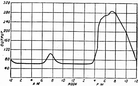
Fig. 1.
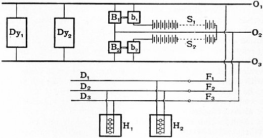
Fig. 2.
Assuming current to be supplied at about 460 volts by different and separate steam dynamos, Dy1, Dy2 (fig. 2), the machines are connected through proper amperemeters and voltmeters with omnibus bars, O1, O2, O3, on a main switchboard, Three-wire system. so that any dynamo can be put in connexion or removed. The switchboard is generally divided into three parts—one panel for the connexions of the positive feeders, F1, with the positive terminals of the generators; one for the negative feeders, F3, and negative generator terminals; while from the third (or middle-wire panel) proceed an equal number of middle-wire feeders, F2. These sets of conductors are led out into the district to be supplied with current, and are there connected into a distributing system, consisting of three separate insulated conductors, D1, D2, D3, respectively called the positive, middle and negative distributing mains. The lamps in the houses, H1, H2, &c., are connected between the middle and negative, and the middle and positive, mains by smaller supply and service wires. As far as possible the numbers of lamps installed on the two sides of the system are kept equal; but since it is not possible to control the consumption of current, it becomes necessary to provide at the station two small dynamos called the balancing machines, B1, B2, connected respectively between the middle and positive and the middle and negative omnibus bars. These machines may have their shafts connected together, or they may be driven by separate steam dynamos; their function is to supply the difference in the total current circulating through the whole of the lamps respectively on the two opposite sides of the middle wire. If storage batteries are employed in the station, it is usual to install two complete batteries, S1, S2, which are placed in a separate battery room and connected between the middle omnibus bar and the two outer omnibus bars. The extra electromotive force required to charge these batteries is supplied by two small dynamos b1, b2, called boosters. It is not unusual to join together the two balancing dynamos and the two boosters on one common bedplate, the shafts being coupled and in line, and to employ the balancing machines as electromotors to drive the boosters as required. By the use of reversible boosters, such as those made by the Lancashire Dynamo & Motor Company under the patents of Turnbull & McLeod, having four field windings on the booster magnets (see The Electrician, 1904, p. 303), it is possible to adjust the relative duty of the dynamos and battery so that the load on the supply dynamos is always constant. Under these conditions the main engines can be worked all the time at their maximum steam economy and a smaller engine plant employed. If the load in the station rises above the fixed amount, the batteries discharge in parallel with the station dynamos; if it falls below, the batteries are charged and the station dynamos take the external load.
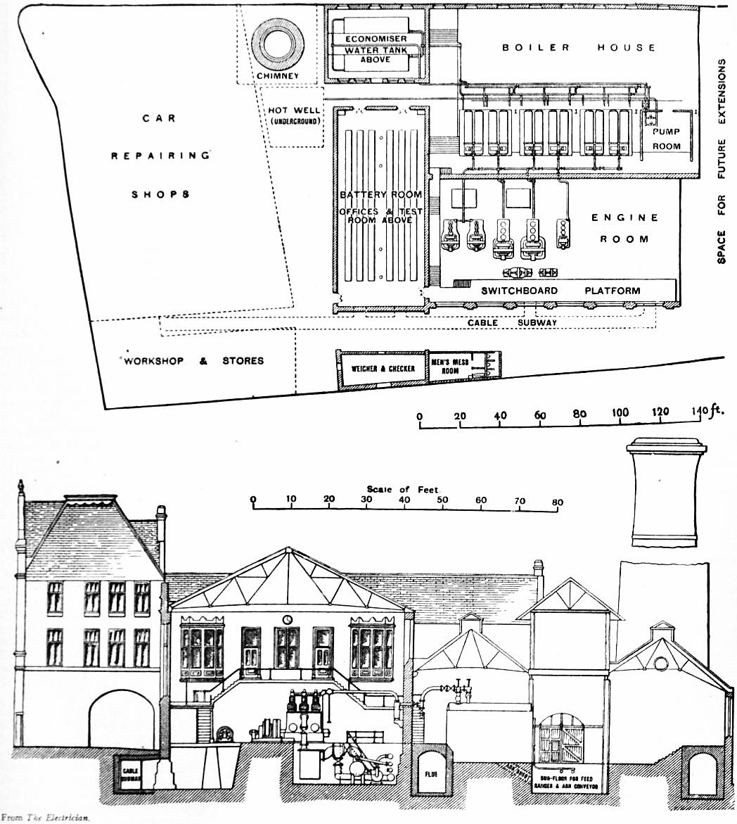
Figs. 3 and 4.—Low-pressure Supply Station.
The general arrangements of a low-pressure supply station are shown in figs. 3 and 4. It consists of a boiler-house containing a bank of boilers, either Lancashire or Babcock & Wilcox being generally used (see Boiler), which furnish steam to the engines Generating stations. and dynamos, provision being made by duplicate steam-pipes or a ring main so that the failure of a single engine or dynamo does not cripple the whole supply. The furnace gases are taken through an economizer (generally Green’s) so that they give up their heat to the cold feed water. If condensing water is available the engines are worked condensing, and this is an essential condition of economy when steam turbines are employed. Hence, either a condensing water pond or a cooling tower has to be provided to cool the condensing water and enable it to be used over and over again. Preferably the station should be situated near a river or canal and a railway siding. The steam dynamos are generally arranged in an engine-room so as to be overlooked from a switchboard gallery (fig. 3), from which all the control is carried out. The boiler furnaces are usually stoked by automatic stokers. Owing to the relatively small load factor (say 8 or 10%) of a station giving electric supply for lighting only, the object of every station engineer is to cultivate a demand for electric current for power during the day-time by encouraging the use of electric motors for lifts and other purposes, but above all to create a demand for traction purposes. Hence most urban stations now supply current not only for electric lighting but for running the town tramway system, and this traction load being chiefly a daylight load serves to keep the plant employed and remunerative. It is usual to furnish a continuous current supply for traction at 500 or 600 volts, although some station engineers are advocating the use of higher voltages. In those stations which supply current for traction, but which have a widely scattered lighting load, double current dynamos are often employed, furnishing from one and the same armature a continuous current for traction purposes, and an alternating current for lighting purposes.
In some places a high voltage system of electric supply by continuous current is adopted. In this case the current is generated at a pressure of 1000 or 2000 volts, and transmitted from the generating station by conductors, High-pressure continuous supply. called high-pressure feeders, to certain sub-centres or transformer centres, which are either buildings above ground or cellars or excavations under the ground. In these transformer centres are placed machines, called continuous-current transformers, which transform the electric energy and create a secondary electric current at a lower pressure, perhaps 100 or 150 volts, to be supplied by distributing mains to users (see Transformers). From these sub-centres insulated conductors are run back to the generating station, by which the engineer can start or stop the continuous-current rotatory transformers, and at the same time inform himself as to their proper action and the electromotive force at the secondary terminals. This system was first put in practice in Oxford, England, and hence has been sometimes called by British engineers “the Oxford system.” It is now in operation in a number of places in England, such as Wolverhampton, Walsall, and Shoreditch in London. It has the advantage that in connexion with the low-pressure distributing system secondary batteries can be employed, so that a storage of electric energy is effected. Further, continuous-current arc lamps can be worked in series off the high-pressure mains, that is to say, sets of 20 to 40 arc lamps can be operated for the purpose of street lighting by means of the high-pressure continuous current.
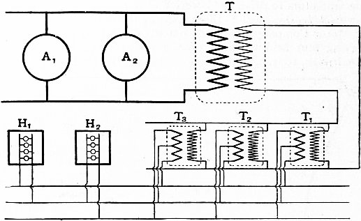
Fig. 5.
The alternating current systems in operation at the present time are the single-phase system, with distributing transformers or transformer sub-centres, and the polyphase systems, in which the alternating current is transformed down Alternating supply. into an alternating current of low pressure, or, by means of rotatory transformers, into a continuous current. The general arrangement of a single-phase alternating-current system is as follows: The generating station contains a number of alternators, A1 A2 (fig. 5), producing single-phase alternating current, either at 1000, 2000, or sometimes, as at Deptford and other places, 10,000 volts. This current is distributed from the station either at the pressure at which it is generated, or after being transformed up to a higher pressure by the transformer T. The alternators are sometimes worked in parallel, that is to say, all furnish their current to two common omnibus bars on a high-pressure switchboard, and each is switched into circuit at the moment when it is brought into step with the other machines, as shown by some form of phase-indicator. In some cases, instead of the high-pressure feeders starting from omnibus bars, each alternator works independently and the feeders are grouped together on the various alternators as required. A number of high-pressure feeders are carried from the main switchboard to various transformer sub-centres or else run throughout the district to which current is to be furnished. If the system laid down is the transformer sub-centre system, then at each of these sub-centres is placed a battery of alternating-current transformers, T1 T2 T3, having their primary circuits all joined in parallel to the terminals of the high-pressure feeders, and their secondary circuits all joined in parallel on a distributing main, suitable switches and cut-outs being interposed. The pressure of the current is then transformed down by these transformers to the required supply pressure. The secondary circuits of these transformers are generally provided with three terminals, so as to supply the low-pressure side on a three-wire system. It is not advisable to connect together directly the secondary circuits of all the different sub-centres, because then a fault or short circuit on one secondary system affects all the others. In banking together transformers in this manner in a sub-station it is necessary to take care that the transformation ratio and secondary drop (see Transformers) are exactly the same, otherwise one transformer will take more than its full share of the load and will become overheated. The transformer sub-station system can only be adopted where the area of supply is tolerably compact. Where the consumers lie scattered over a large area, it is necessary to carry the high-pressure mains throughout the area, and to place a separate transformer or transformers in each building. From a financial point of view, this “house-to-house system” of alternating-current supply, generally speaking, is less satisfactory in results than the transformer sub-centre system. In the latter some of the transformers can be switched off, either by hand or by automatic apparatus, during the time when the load is light, and then no power is expended in magnetizing their cores. But with the house-to-house system the whole of the transformers continually remain connected with the high-pressure circuits; hence in the case of supply stations which have only an ordinary electric lighting load, and therefore a load-factor not above 10%, the efficiency of distribution is considerably diminished.
The single-phase alternating-current system is defective in that it cannot be readily combined with secondary batteries for the storage of electric energy. Hence in many places preference is now given to the polyphase system. In such a system a polyphase alternating current, either two- or three-phase, is transmitted from the generating station at a pressure of 5000 to 10,000 volts, or sometimes higher, and at various sub-stations is transformed down, first by static transformers into an alternating current of lower pressure, say 500 volts, and then by means of rotatory transformers into a continuous current of 500 volts or lower for use for lighting or traction.
In the case of large cities such as London, New York, Chicago, Berlin and Paris the use of small supply stations situated in the interior of the city has gradually given way to the establishment of large supply stations outside the area; in these alternating current is generated on the single or polyphase system at a high voltage and transmitted by underground cables to sub-stations in the city, at which it is transformed down for distribution for private and public electric lighting and for urban electric traction.
Owing to the high relative cost of electric power when generated in small amounts and the great advantages of generating it in proximity to coal mines and waterfalls, the supply of electric power in bulk to small towns and manufacturing districts has become a great feature in modern electrical engineering. In Great Britain, where there is little useful water power but abundance of coal, electric supply stations for supply in bulk have been built in the coal-producing districts of South Wales, the Midlands, the Clyde valley and Yorkshire. In these cases the current is a polyphase current generated at a high voltage, 5000 to 10,000 volts, and sometimes raised again in pressure to 20,000 or 40,000 volts and transmitted by overhead lines to the districts to be supplied. It is there reduced in voltage by transformers and employed as an alternating current, or is used to drive polyphase motors coupled to direct current generators to reproduce the power in continuous current form. It is then distributed for local lighting, street or railway traction, driving motors, and metallurgical or electrochemical applications. Experience has shown that it is quite feasible to distribute in all directions for 25 miles round a high-pressure generating station, which thus supplies an area of nearly 2000 sq. m. At such stations, employing large turbine engines and alternators, electric power may be generated at a works cost of 0.375d. per kilowatt (K.W.), the coal cost being less than 0.125d. per K.W., and the selling price to large load-factor users not more than 0.5d. per K.W. The average price of supply from the local generating stations in towns and cities is from 3d. to 4d. per unit, electric energy for power and heating being charged at a lower rate than that for lighting only.
We have next to consider the structure and the arrangement of the conductors employed to convey the currents from their place of creation to that of utilization. The conductors themselves for the most part consist of copper having Conductors. a conductivity of not less than 98% according to Matthiessen’s standard. They are distinguished as (1) External conductors, which are a part of the public supply and belong to the corporation or company supplying the electricity; (2) Internal conductors, or house wiring, forming a part of the structure of the house or building supplied and usually the property of its owner.
The external conductors may be overhead or underground. Overhead conductors may consist of bare stranded copper cables carried on porcelain insulators mounted on stout iron or wooden poles. If the current is a high-pressure External conductors. one, these insulators must be carefully tested, and are preferably of the pattern known as oil insulators. In and near towns it is necessary to employ insulated overhead conductors, generally india-rubber-covered stranded copper cables, suspended by leather loops from steel bearer wires which take the weight. The British Board of Trade have issued elaborate rules for the construction of overhead lines to transmit large electric currents. Where telephone and telegraph wires pass over such overhead electric lighting wires, they have to be protected from falling on the latter by means of guard wires.
By far the largest part, however, of the external electric distribution is now carried out by underground conductors, which are either bare or insulated. Bare copper conductors may be carried underground in culverts or chases, air being in this case the insulating material, as in the overhead system. A culvert and covered chase is constructed under the road or side-walk, and properly shaped oak crossbars are placed in it carrying glass or porcelain insulators, on which stranded copper cables, or, preferably, copper strips placed edgeways, are stretched and supported. The advantages of this method of construction are cheapness and the ease with which connexions can be made with service-lines for house supply; the disadvantages are the somewhat large space in which coal-gas leaking out of gas-pipes can accumulate, and the difficulty of keeping the culverts at all times free from rain-water. Moisture has a tendency to collect on the negative insulators, and hence to make a dead earth on the negative side of the main; while unless the culverts are well ventilated, explosions from mixtures of coal-gas and air are liable to occur. Insulated cables are insulated either with a material which is in itself waterproof, or with one which is only waterproof in so far as it is enclosed in a waterproof tube, e.g. of lead. Gutta-percha and india-rubber are examples of materials of the former kind. Gutta-percha, although practically everlasting when in darkness and laid under water, as in the case of submarine cables, has not been found satisfactory for use with large systems of electric distribution, although much employed for telephone and telegraph work. Insulated underground external conductors are of three types:—(a) Insulated Cables drawn into Pipes.—In this system of distribution cast-iron or stoneware pipes, or special stoneware conduits, or conduits made of a material called bitumen concrete, are first laid underground in the street. These contain a number of holes or “ways,” and at intervals drawing-in boxes are placed which consist of a brick or cast-iron box having a water-tight lid, by means of which access is gained to a certain section of the conduit. Wires are used to draw in the cables, which are covered with either india-rubber or lead, the copper being insulated by means of paper, impregnated jute, or other similar material. The advantages of a drawing-in system are that spare ways can be left when the conduits are put in, so that at a future time fresh cables can be added without breaking up the roadway. (b) Cables in Bitumen.—One of the earliest systems of distribution employed by T.A. Edison consisted in fixing two segment-shaped copper conductors in a steel tube, the interspace between the conductors and the tube being filled in with a bitumen compound. A later plan is to lay down an iron trough, in which the cables are supported by wooden bearers at proper distances, and fill in the whole with natural bitumen. This system has been carried out extensively by the Callendar Cable Company. Occasionally concentric lead-covered and armoured cables are laid in this way, and then form an expensive but highly efficient form of insulated conductor. In selecting a system of distribution regard must be paid to the nature of the soil in which the cables are laid. Lead is easily attacked by soft water, although under some conditions it is apparently exceedingly durable, and an atmosphere containing coal-gas is injurious to india-rubber. (c) Armoured Cables.—In a very extensively used system of distribution armoured cables are employed. In this case the copper conductors, two, three or more in number, may be twisted together or arranged concentrically, and insulated by means of specially prepared jute or paper insulation, overlaid with a continuous tube of lead. Over the lead, but separated by a hemp covering, is put a steel armour consisting of two layers of steel strip, wound in opposite directions and kept in place by an external covering. Such a cable can be laid directly in the ground without any preparation other than the excavation of a simple trench, junction-boxes being inserted at intervals to allow of branch cables being taken off. The armoured cable used is generally of the concentric pattern (fig. 6). It consists of a stranded copper cable composed of a number of wires twisted together and overlaid with an insulating material. Outside this a tubular arrangement of copper wires and a second layer of insulation, and finally a protective covering of lead and steel wires or armour are placed. In some cases three concentric cylindrical conductors are formed by twisting wires or copper strips with insulating material between. In others two or three cables of stranded copper are embedded in insulating material and included in a lead sheath. This last type of cable is usually called a two- or three-core pattern cable (fig. 7).
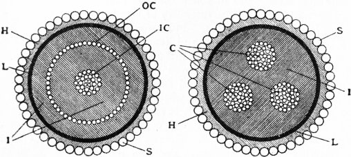
Fig. 6.—Armoured Concentric Cable (Section). Fig. 7.—Triple Conductor Armoured Cable (Section).
IC, Inner conductor. OC, Outer conductor. I, Insulation. L, Lead sheath. S, Steel armour. H, Hemp covering. C, Copper conductor. I, Insulation. L, Lead sheath. H, Hemp covering. S, Steel armour.
The arrangement and nature of the external conductors depends on the system of electric supply in which they are used. In the case of continuous-current supply for incandescent electric lighting and motive power in small units, when the external conductors are laid down on the three-wire system, each main or branch cable in the street consists of a set of three conductors called the positive, middle and negative. Of these triple conductors some run from the supply station to various points in the area of supply without being tapped, and are called the feeders; others, called the distributing mains, are used for making connexions with the service lines of the consumers, one service line, as already explained, being connected to the middle conductor, and the other to either the positive or the negative one. Since the middle conductor serves to convey only the difference between the currents being used on the two sides of the system, it is smaller in section than the positive and negative ones. In laying out the system great judgment has to be exercised as to the selection of the points of attachment of the feeders to the distributing mains, the object being to keep a constant electric pressure or voltage between the two service-lines in all the houses independently of the varying demand for current. Legally the suppliers are under regulations to keep the supply voltage constant within 4% either way above or below the standard pressure. As a matter of fact very few stations do maintain such good regulation. Hence a considerable variation in the light given by the incandescent lamps is observed, since the candle-power of carbon glow lamps varies as the fifth or sixth power of the voltage of supply, i.e. a variation of only 2% in the supply pressure affects the resulting candle-power of the lamps to the extent of 10 or 12%. This variation is, however, less in the case of metallic filament lamps (see Lighting: Electric). In the service-lines are inserted the meters for measuring the electric energy supplied to the customer (see Meter, Electric).
In the interior of houses and buildings the conductors generally consist of india-rubber-covered cables laid in wood casing. The copper wire must be tinned and then covered, first with a layer of unvulcanized pure india-rubber, Interior wiring. then with a layer of vulcanized rubber, and lastly with one or more layers of protective cotton twist or tape. No conductor of this character employed for interior house-wiring should have a smaller insulation resistance than 300 megohms per mile when tested with a pressure of 600 volts after soaking 24 hours in water. The wood casing should, if placed in damp positions or under plaster, be well varnished with waterproof varnish. As far as possible all joints in the run of the cable should be avoided by the use of the so-called looping-in system, and after the wiring is complete, careful tests for insulation should be made. The Institution of Electrical Engineers of Great Britain have drawn up rules to be followed in interior house-wiring, and the principal Fire Insurance offices, following the lead of the Phoenix Fire Office, of London, have made regulations which, if followed, are a safeguard against bad workmanship and resulting possibility of damage by fire. Where fires having an electric origin have taken place, they have invariably been traced to some breach of these rules. Opinions differ, however, as to the value and security of this method of laying interior conductors in buildings, and two or three alternative systems have been much employed. In one of these, called the interior conduit system, highly insulating waterproof and practically fireproof tubes or conduits replace the wooden casing; these, being either of plain insulating material, or covered with brass or steel armour, may be placed under plaster or against walls. They are connected by bends or joint-boxes. The insulated wires being drawn into them, any short circuit or heating of the wire cannot give rise to a fire, as it can only take place in the interior of a non-inflammable tube. A third system of electric light wiring is the safety concentric system, in which concentric conductors are used. The inner one, which is well insulated, consists of a copper-stranded cable. The outer may be a galvanized iron strand, a copper tape or braid, or a brass tube, and is therefore necessarily connected with the earth. A fourth system consists in the employment of twin insulated wires twisted together and sheathed with a lead tube; the conductor thus formed can be fastened by staples against walls, or laid under plaster or floors.
The general arrangement for distributing current to the different portions of a building for the purpose of electric lighting is to run up one or more rising mains, from which branches are taken off to distributing boxes on each floor, and from these boxes to carry various branch circuits to the lamps. At the distributing boxes are collected the cut-outs and switches controlling the various circuits. When alternating currents are employed, it is usual to select as a type of conductor either twin-twisted conductor or concentric; and the employment of these types of cable, rather than two separate cables, is essential in any case where there are telephone or telegraph wires in proximity, for otherwise the alternating current would create inductive disturbances in the telephone circuit. The house-wiring also comprises the details of switches for controlling the lamps, cut-outs or fuses for preventing an excess of current passing, and fixtures or supports for lamps often of an ornamental character. For the details of these, special treatises on electric interior wiring must be consulted.
For further information the reader may be referred to the following books:—C.H. Wordingham, Central Electrical Stations (London, 1901); A. Gay and C.Y. Yeaman, Central Station Electricity Supply (London, 1906); S.P. Thompson, Dynamo Electric Machinery (2 vols., London, 1905); E. Tremlett Carter and T. Davies, Motive Power and Gearing (London, 1906); W.C. Clinton, Electric Wiring (2nd ed., London, 1906); W. Perren Maycock, Electric Wiring, Fitting, Switches and Lamps (London, 1899); D. Salomons, Electric Light Installations (London, 1894); Stuart A. Russell, Electric Light Cables (London, 1901); F.A.C. Perrine, Conductors for Electrical Distribution (London, 1903); E. Rosenberg, W.W. Haldane Gee and C. Kinzbrunner, Electrical Engineering (London, 1903); E.C. Metcalfe, Practical Electric Wiring for Lighting Installations (London, 1905); F.C. Raphael, The Wireman’s Pocket Book (London, 1903).
(J. A. F.)
II. Commercial Aspects.—To enable the public supply enterprises referred to in the foregoing section to be carried out in England, statutory powers became necessary to break up the streets. In the early days a few small stations History. were established for the supply of electricity within “block” buildings, or by means of overhead wires within restricted areas, but the limitations proved uneconomical and the installations were for the most part merged into larger undertakings sanctioned by parliamentary powers. In the year 1879 the British government had its attention directed for the first time to electric lighting as a possible subject for legislation, and the consideration of the then existing state of electric lighting was referred to a select committee of the House of Commons. No legislative action, however, was taken at that time. In fact the invention of the incandescent lamp was incomplete—Edison’s British master-patent was only filed in Great Britain in November 1879. In 1881 and 1882 electrical exhibitions were held in Paris and at the Crystal Palace, London, where the improved electric incandescent lamp was brought before the general public. In 1882 parliament passed the first Electric Lighting Act, and considerable speculation ensued. The aggregate capital of the companies registered in 1882-1883 to carry out the public supply of electricity in the United Kingdom amounted to £15,000,000, but the onerous conditions of the act deterred investors from proceeding with the enterprise. Not one of the sixty-two provisional orders granted to companies in 1883 under the act was carried out. In 1884 the Board of Trade received only four applications for provisional orders, and during the subsequent four years only one order was granted. Capitalists declined to go on with a business which if successful could be taken away from them by local authorities at the end of twenty-one years upon terms of paying only the then value of the plant, lands and buildings, without regard to past or future profits, goodwill or other considerations. The electrical industry in Great Britain ripened at a time when public opinion was averse to the creation of further monopolies, the general belief being that railway, water and gas companies had in the past received valuable concessions on terms which did not sufficiently safeguard the interests of the community. The great development of industries by means of private enterprise in the early part of the 19th century produced a reaction which in the latter part of the century had the effect of discouraging the creation by private enterprise of undertakings partaking of the nature of monopolies; and at the same time efforts were made to strengthen local and municipal institutions by investing them with wider functions. There were no fixed principles governing the relations between the state or municipal authorities and commercial companies rendering monopoly services. The new conditions imposed on private enterprise for the purpose of safeguarding the interests of the public were very tentative, and a former permanent secretary of the Board of Trade has stated that the efforts made by parliament in these directions have sometimes proved injurious alike to the public and to investors. One of these tentative measures was the Tramways Act 1870, and twelve years later it was followed by the first Electric Lighting Act.
It was several years before parliament recognized the harm that had been done by the passing of the Electric Lighting Act 1882. A select committee of the House of Lords sat in 1886 to consider the question of reform, and as a result the Electric Lighting Act 1888 was passed. This amending act altered the period of purchase from twenty-one to forty-two years, but the terms of purchase were not materially altered in favour of investors. The act, while stipulating for the consent of local authorities to the granting of provisional orders, gives the Board of Trade power in exceptional cases to dispense with the consent, but this power has been used very sparingly. The right of vetoing an undertaking, conferred on local authorities by the Electric Lighting Acts and also by the Tramways Act 1870, has frequently been made use of to exact unduly onerous conditions from promoters, and has been the subject of complaint for years. Although, in the opinion of ministers of the Crown, the exercise of the veto by local authorities has on several occasions led to considerable scandals, no government has so far been able, owing to the very great power possessed by local authorities, to modify the law in this respect. After 1888 electric lighting went ahead in Great Britain for the first time, although other countries where legislation was different had long previously enjoyed its benefits. The developments proceeded along three well-defined lines. In London, where none of the gas undertakings was in the hands of local authorities, many of the districts were allotted to companies, and competition was permitted between two and sometimes three companies. In the provinces the cities and larger towns were held by the municipalities, while the smaller towns, in cases where consents could be obtained, were left to the enterprise of companies. Where consents could not be obtained these towns were for some time left without supply.
Some statistics showing the position of the electricity supply business respectively in 1896 and 1906 are interesting as indicating the progress made and as a means of comparison between these two periods of the state of the industry as a whole. In 1896 thirty-eight companies were at work with an aggregate capital of about £6,000,000, and thirty-three municipalities with electric lighting loans of nearly £2,000,000. The figures for 1906, ten years later, show that 187 electricity supply companies were in operation with a total investment of close on £32,000,000, and 277 municipalities with loans amounting to close on £36,000,000. The average return on the capital invested in the companies at the later period was 5.1% per annum. In 1896 the average capital expenditure was about £100 per kilowatt of plant installed; and £50 per kilowatt was regarded as a very low record. For 1906 the average capital expenditure per kilowatt installed was about £81. The main divisions of the average expenditure are:—
1896. 1906.
Land and buildings 22.3% 17.8%
Plant and machinery 36.7 36.5
Mains 32.2 35.5
Meters and instruments 4.6 5.7
Provisional orders, &c. 3.2 2.8
The load connected, expressed in equivalents of eight candle-power lamps, was 2,000,000 in 1896 and 24,000,000 in 1906. About one-third of this load would be for power purposes and about two-thirds for lighting. The Board of Trade units sold were 30,200,000 in 1896 and 533,600,000 in 1906, and the average prices per unit obtained were 5.7d. and 2.7d. respectively, or a revenue of £717,250 in 1896 and over £6,000,000 in 1906. The working expenses per Board of Trade unit sold, excluding depreciation, sinking fund and interest were as follows:—
1896. 1906.
Generation and distribution 2.81d. .99d.
Rent, rates and taxes .35 .14
Management .81 .18
Sundries .10 .02
——— ———
Total 4.07d. 1.33d.
In 1896 the greatest output at one station was about 5½ million units, while in 1906 the station at Manchester had the largest output of over 40 million units.
The capacity of the plants installed in the United Kingdom in 1906 was:—