VOLUME VI SLICE V Clervaux to Cockade (continued 9)
Reading edition
When the cage arrives at the surface, or rather the platform forming the working top above the mouth of the pit, it is received upon the keeps, a pair of hinged gratings which are kept in an inclined position over the pit-top by counter-balance Striking and screening. weights, so that they are pushed aside to allow the cage to pass upwards, but fall back and receive it when the engine is reversed. The tubs are then removed or struck by the landers, who pull them forward on to the platform, which is covered with cast iron plates; at the same time empty ones are pushed in from the opposite side. The cage is then lifted by the engine clear of the keeps, which are opened by a lever worked by hand, and the empty tubs start on the return trip. When the cage has several decks, it is necessary to repeat this operation for each, unless there is a special provision made for loading and discharging the tubs at different levels. An arrangement of this kind for shifting the load from a large cage at one operation was introduced by Fowler at Hucknall, in Leicestershire, where the trains are received into a framework with a number of platforms corresponding to those of the cage, carried on the head of a plunger movable by hydraulic pressure in a vertical cylinder. The empty tubs are carried by a corresponding arrangement on the opposite side. By this means the time of stoppage is reduced to a minimum, 8 seconds for a three-decked cage as against 28 seconds, as the operations of lowering the tubs to the level of the pit-top, discharging, and replacing them are performed during the time that the following load is being drawn up the pit.
In the United Kingdom the drawing of coal is generally confined to the day shift of eight hours, with an output of from 100 to 150 tons per hour, according to the depth, capacity of coal tubs, and facilities for landing and changing tubs. With Fowler’s hydraulic arrangement 2000 tons are raised 600 yds. in eight hours. In the deeper German pits, where great thicknesses of water-bearing strata have to be traversed, the first establishment expenses are so great that in order to increase output the shaft is sometimes provided with a complete double equipment of cages and engines. In such cases the engines may be placed in line on opposite sides of the pit, or at right angles to each other. It is said that the output of single shafts has been raised by this method to 3500 and 4500 tons in the double shift of sixteen hours. It is particularly well suited to mines where groups of seams at different depths are worked simultaneously. Some characteristic figures of the yield for British collieries in 1898 are given below:—
Albion Colliery, South Wales 551,000 tons in a year for one shaft and one engine.
Silksworth Colliery, Northumberland 535,000 tons in a year for shaft 580 yds. deep, two engines.
Bolsover Colliery, Derby 598,798 tons in 279 days, shaft 365 yds. deep.
Denaby Main Colliery, Yorkshire 629,947 tons in 281 days, maximum per day 2673 tons.
At Cadeby Main colliery near Doncaster in 1906, 3360 tons were drawn in fourteen hours from one pit 763 yds. deep.
The tub when brought to the surface, after passing over a weigh-bridge where it is weighed and tallied by a weigher specially appointed for the purpose by the men and the owner jointly, is run into a “tippler,” a cage turning about a horizontal axis which discharges the load in the first half of the rotation and brings the tub back to the original position in the second. It is then run back to the pit-bank to be loaded into the cage at the return journey.
Coal as raised from the pit is now generally subjected to some final process of classification and cleaning before being despatched to the consumer. The nature and extent of these operations vary with the character of the coal, which if hard and free from shale partings may be finished by simple screening into large and nut sizes and smaller slack or duff, with a final hand-picking to remove shale and dust from the larger sizes. But when there is much small duff, with intermixed shale, more elaborate sizing and washing plant becomes necessary. Where hand-picking is done, the larger-sized coal, separated by 3-in. bar screens, is spread out on a travelling band, which may be 300 ft. long and from 3 to 5 wide, and carried past a line of pickers stationed along one side, who take out and remove the waste as it passes by, leaving the clean coal on the belt. The smaller duff is separated by vibrating or rotating screens into a great number of sizes, which are cleaned by washing in continuous current or pulsating jigging machines, where the lighter coal rises to the surface and is removed by a stream of water, while the heavier waste falls and is discharged at a lower level, or through a valve at the bottom of the machine. The larger or “nut” sizes, from ¼ in. upwards, are washed on plain sieve plates, but for finer-grained duff the sieve is covered with a bed of broken felspar lumps about 3 in. thick, forming a kind of filter, through which the fine dirt passes to the bottom of the hutch. The cleaned coal is carried by a stream of water to a bucket elevator and delivered to the storage bunkers, or both water and coal may be lifted by a centrifugal pump into a large cylindrical tank, where the water drains away, leaving the coal sufficiently dry for use. Modern screening and washing plants, especially when the small coal forms a considerable proportion of the output, are large and costly, requiring machinery of a capacity of 100 to 150 tons per hour, which absorbs 350 to 400 H.P. In this, as in many other cases, electric motors supplied from a central station are now preferred to separate steam-engines.
Anthracite coal in Pennsylvania is subjected to breaking between toothed rollers and an elaborate system of screening, before it is fit for sale. The largest or lump coal is that which remains upon a riddle having the bars 4 in. apart; the second, or steamboat coal, is above 3 in.; broken coal includes sizes above 2½ or 2¾ in.; egg coal, pieces above 2¼ in. sq.; large stove coal, 1¾ in.; small stove, 1 to 1½ or 11⁄3 in.; chestnut coal, 2⁄3 to ¾ in.; pea coal, ½ in.; and buckwheat coal, 1⁄3 in. The most valuable of these are the egg and stove sizes, which are broken to the proper dimensions for household use, the larger lumps being unfit for burning in open fire-places. In South Wales a somewhat similar treatment is now adopted in the anthracite districts.
With the increased activity of working characteristic of modern coal mining, the depth of the mines has rapidly increased, and at the present time the level of 4000 ft., formerly Depth of working. assumed as the possible limit for working, has been nearly attained. The following list gives the depths reached in the deepest collieries in Europe in 1900, from which it will be seen that the larger number, as well as the deepest, are in Belgium:—
Metres. Ft.
Saint Henriette, Cie des Produits, Flenu, Belgium 1150 3773
Viviers Gilly ” 1143 3750
Marcinelle, No. 11, Charleroi ” 1075 3527
Marchienne, No. 2, Charleroi ” 1065 3494
Agrappe, Mons ” 1060 3478
Pendleton dip workings Lancashire 1059 3474
Sacré Madame, Charleroi Belgium 1055 3461
Ashton Moss dip workings Lancashire 1024 3360
Ronchamp, No. 11 pit France 1015 3330
Viernoy, Anderlues Belgium 1006 3301
Astley Pit, Dukinfield, dip workings Cheshire 960 3150
Saint André, Poirier, Charleroi Belgium 950 3117
The greatest depth attained in the Westphalian coal is at East Recklinghausen, where there are two shafts 841 metres (2759 ft.) deep.
The subject of the limiting depth of working has been very fully studied in Belgium by Professor Simon Stassart of Mons (“Les Conditions d’exploitation à grande profondeur en Belgique,” Bulletin de la Société de l’Industrie minérale, 3 ser., vol. xiv.), who finds that no special difficulty has been met with in workings above 1100 metres deep from increased temperature or atmospheric pressure. The extreme temperatures in the working faces at 1150 metres were 79° and 86° F., and the maximum in the end of a drift, 100°; and these were quite bearable on account of the energetic ventilation maintained, and the dryness of the air. The yield per man on the working faces was 4.5 tons, and for the whole of the working force underground, 0.846 tons, which is not less than that realized in shallower mines. From the experience of such workings it is considered that 1500 metres would be a possible workable depth, the rock temperature being 132°, and those of the intake and return galleries, 92° and 108° respectively. Under such conditions work would be practically impossible except with very energetic ventilation and dry air. It would be scarcely possible to circulate more than 120,000 to 130,000 cub. ft. per minute under such conditions, and the number of working places would thus be restricted, and consequently the output reduced to about 500 tons per shift of 10 hours, which could be raised by a single engine at the surface without requiring any very different appliances from those in current use.
In the United Kingdom the ownership of coal, like that of other minerals, is in the proprietor of the soil, and passes with it, except when specially reserved in the sale. Coal lying under the sea below low-water mark belongs to the Ownership of coal. crown, and can only be worked upon payment of royalties, even when it is approached from shafts sunk upon land in private ownership. In the Forest of Dean, which is the property of the crown as a royal forest, there are certain curious rights held by a portion of the inhabitants known as the Free Miners of the Forest, who are entitled to mine for coal and iron ore, under leases, known as gales, granted by the principal agent or gaveller representing the crown, in tracts not otherwise occupied. This is the only instance in Great Britain of the custom of free coal-mining under a government grant or concession, which is the rule in almost every country on the continent of Europe.
The working of collieries in the United Kingdom is subject to the provisions of the Coal Mines Regulation Act 1887, as amended by several minor acts, administered by inspectors Coal Mines Regulation Act. appointed by the Home Office, and forming a complete disciplinary code in all matters connected with coal-mining. An important act was passed in 1908, limiting the hours of work below ground of miners. For a detailed account of these various acts see the article Labour Legislation.
Coal-mining is unfortunately a dangerous occupation, more than a thousand deaths from accident being reported Accidents. annually by the inspectors of mines as occurring in the collieries of the United Kingdom.
The number of lives lost during the year 1906 was, according to the inspectors’ returns:—
From explosions 54
From falls of ground 547
From other underground accidents 328
From accidents in shafts 65
From surface accidents 135
——
Total 1129
The principal sources of danger to the collier, as distinguished from other miners, are explosions of fire-damp and falls of roof in getting coal; these together make up about 70% of the whole number of deaths. It will be seen that the former class of accidents, though often attended with great loss of life at one time, are less fatal than the latter.
Authorities.—The most important new publication on British coal is that of the royal commission on coal supplies appointed in 1901, whose final report was issued in 1905. A convenient digest of the evidence classified according to subjects was published by the Colliery Guardian newspaper in three quarto volumes in 1905-1907, and the leading points bearing on the extension and resources of the different districts were incorporated in the fifth edition (1905) of Professor Edward Hull’s Coal Fields of Great Britain. The Report of the earlier royal commission (1870), however, still remains of great value, and must not be considered to have had its conclusions entirely superseded. In connexion with the re-survey in greater detail of the coalfields by the Geological Survey a series of descriptive memoirs were undertaken, those on the North Staffordshire and Leicestershire fields, and nine parts dealing with that of South Wales, having appeared by the beginning of 1908.
An independent work on the coal resources of Scotland under the title of the Coalfields of Scotland, by R. W. Dixon, was published in 1902.
The Rhenish-Westphalian coalfield was fully described in all details, geological, technical and economic, in a work called Die Entwickelung des niederrheinisch-westfälischen Steinkohlen Bergbaues in der zweiten Hälfte des 19ten Jahrhunderts (also known by the short title of Sammelwerk) in twelve quarto volumes, issued under the auspices of the Westphalian Coal Trade Syndicate (Berlin, 19O2-1905).
The coalfields of the Austrian dominions (exclusive of Hungary) are described in Die Mineralkohlen Österreichs, published at Vienna by the Central Union of Austrian mineowners. It continues the table of former official publications in 1870 and 1878, but in much more detail than its predecessors.
Systematic detailed descriptions of the French coalfields appear from time to time under the title of Études sur les gîtes minéraux de la France from the ministry of public works in Paris.
Much important information on American coals will be found in the three volumes of Reports on the Coal Testing Plant at the St Louis Exhibition, published by the United States Geological Survey in 1906. A special work on the Anthracite Coal Industry of the United States, by P. Roberts, was published in 1901.
The most useful general work on coal mining is the Text Book of Coal Mining, by H. W. Hughes, which also contains detailed bibliographical lists for each division of the text. The 5th edition appeared in 1904.
Current progress in mining and other matters connected with coal can best be followed by consulting the abstracts and bibliographical lists of memoirs on these subjects that have appeared in the technical journals of the world contained in the Journal of the Institute of Mining Engineers and that of the Iron and Steel Institute. The latter appears at half-yearly intervals and includes notices of publications up to about two or three months before the date of its publication.
(H. B.)
COALBROOKDALE, a town and district in the Wellington parliamentary division of Shropshire, England. The town has a station on the Great Western railway, 160 m. N.W. from London. The district or dale is the narrow and picturesque valley of a stream rising near the Wrekin and following a course of some 8 m. in a south-easterly direction to the Severn. Great ironworks occupy it. They were founded in 1709 by Abraham Darby with the assistance of Dutch workmen, and continued by his son and descendants. Father and son had a great share in the discovery and elaboration of the use of pit-coal for making iron, which revolutionized and saved the English iron trade. The father hardly witnessed the benefits of the enterprise, but the son was fully rewarded. It is recorded that he watched the experimental filling of the furnace ceaselessly for six days and nights, and that, just as fatigue was overcoming him, he saw the molten metal issuing, and knew that the experiment had succeeded.
The third Abraham Darby built the famous Coalbrookdale iron bridge over the Severn, which gives name to the neighbouring town of Ironbridge, which with a portion of Coalbrookdale is in the parish of Madeley (q.v.). Fine wrought iron work is produced, and the school of art is well known. There are also brick and tile works.
COAL-FISH (Gadus virens), also called green cod, black pollack, saith and sillock, a fish of the family Gadidae. It has a very wide range, which nearly coincides with that of the cod, although of a somewhat more southern character, as it extends to both east and west coasts of the North Atlantic, and is occasionally found in the Mediterranean. It is especially common in the north, though rarely entering the Baltic; it becomes rare south of the English Channel. Unlike the cod and haddock, the coal-fish is, to a great extent, a surface-swimming fish, congregating together in large schools, and moving from place to place in search of food; large specimens (3 to 3½ ft. long), however, prefer deep water, down to 70 fathoms. The flesh is not so highly valued as that of the cod and haddock. The lower jaw projects more or less beyond the upper, the mental barble is small, sometimes rudimentary, the vent is below the posterior half of the first dorsal fin, and there is a dark spot in the axil of the pectoral fin.
COALING STATIONS. Maritime war in all ages has required that the ships of the belligerents should have the use of sheltered waters for repairs and for replenishment of supplies. The operations of commerce from the earliest days demanded natural harbours, round which, as in the conspicuous instance of Syracuse, large populations gathered. Such points, where wealth and resources of all kinds accumulated, became objects of attack, and great efforts were expended upon their capture. As maritime operations extended, the importance of a seaboard increased, and the possession of good natural harbours became more and more advantageous. At the same time, the growing size of ships and the complexity of fitments caused by the development of the sailing art imposed new demands upon the equipment of ports alike for purposes of construction and for repairs; while the differentiation between warships and the commercial marine led to the establishment of naval bases and dockyards provided with special resources. From the days when the great sailors of Elizabeth carried war into distant seas, remote harbours began to assume naval importance. Expeditionary forces required temporary bases, such as Guantanamo Bay, in Cuba, which was so utilized by Admiral Vernon in 1741. As outlying territories began to be occupied, and jurisdiction to be exercised over their ports, the harbours available for the free use of a belligerent were gradually reduced in number, and it became occasionally necessary to take them by force. Thus, in 1782, the capture of Trincomalee was an object of sufficient importance to justify special effort, and Suffren gained a much-needed refuge for his ships, at the same time compelling his opponent to depend upon the open roadstead of Madras, and even to send ships to Bombay. In this case a distant harbour acquired strategic importance, mainly because sheltered waters, in the seas where Hughes and Suffren strove for naval supremacy, were few and far between. A sailing man-of-war usually carried from five to six months’ provisions and water for 100 to 120 days. Other needs required to be met, and during the wars of the French Revolution it was usual, when possible, to allow ships engaged in blockade to return to port every five or six weeks “to refresh.” For a sailing fleet acting on the offensive, a port from which it could easily get to sea was a great advantage. Thus Raleigh protested against the use of closely landlocked harbours. “Certain it is,” he wrote, “that these ships are purposely to serve His Majesty and to defend the kingdom from danger, and not to be so penned up from casualitie as that they should be less able or serviceable in times of need.” Nelson for this reason made great use of Maddalena Bay, in Sardinia, and was not greatly impressed with the strategic value of Malta in spite of its fine natural harbour. The introduction of steam gave rise to a new naval requirement—coal—which soon became vital. Commerce under steam quickly settled down upon fixed routes, and depots of coal were established to meet its needs. Coaling stations thus came into existence by a natural process, arising from the exigencies of trade, and began later to supply the needs of navies.
For many years there was no inquiry into the war requirements of the British fleet as regards coal, and no attempt to regularize or to fortify the ports at which it was stored. Successful naval war had won for Great Britain many British coaling stations. points of vantage throughout the world, and in some cases the strategic value of ports had been proved by actual experience. The extreme importance of the Cape of Good Hope, obscured for a time after the opening of the Suez Canal, was fully realized in sailing days, and the naval conditions of those days to some extent determined the choice of islands and harbours for occupation. There does not, however, appear to have been any careful study of relative strategic values. Treaties were occasionally drafted by persons whose geographical knowledge was at fault, and positions were, in some cases, abandoned which ought to have been retained, or tenaciously held when they might have been abandoned. It was left to the personal exertions of Sir Stamford Raffles to secure such a supremely important roadstead as that of Singapore for the empire. Although, therefore, the relative values of positions was not always recognized, Great Britain obtained as a legacy from sailing days a large number of harbours admirably adapted for use as coaling stations. Since the dawn of the era of steam, she has acquired Aden, Perim, Hong-Kong, North Borneo, Fiji, part of New Guinea, Fanning Island, and many other islands in the Pacific, while the striking development of Australia and New Zealand has added to the long roll of British ports. The coaling stations, actual and potential, of the empire are unrivalled in number, in convenience of geographical distribution, and in resources. Of the numerous British ports abroad which contained coal stores, only the four so-called “fortresses”—Gibraltar, Malta, Halifax and Bermuda—were at first fortified as naval stations after the introduction of rifled ordnance. The term fortress is a misnomer in every case except Gibraltar, which, being a peninsula separated only by a neck of neutral ground from the territory of a foreign power, exists under fortress conditions. Large sums were expended on these places with little regard to principles, and the defences of Bermuda, which were very slowly constructed, are monuments of misapplied ingenuity.
In 1878 great alarm arose from strained relations with Russia. Rumours of the presence of Russian cruisers in many waters, and of hostile projects, were readily believed, although the Russian navy, which had just shown itself unable Carnarvon Commission. to face that of Turkey, would at this period have been practically powerless. Widespread fears for the security of coaling stations led to the appointment of a strong royal commission, under the presidency of the earl of Carnarvon, which was instructed to inquire into and report upon the protection of British commerce at sea. This was the first attempt to formulate any principles, or to determine which of the many ports where coal was stored should be treated as coaling stations essential for the purposes of war. The terms of the reference to the commission were ill-conceived. The basis of all defence of sea-borne commerce is a mobile navy. It is the movement of commerce upon the sea during war, not its security in port, that is essential to the British empire, and a navy able to protect commerce at sea must evidently protect ports and coaling stations. The first object of inquiry should, therefore, have been to lay down the necessary standard of naval force. The vital question of the navy was not referred to the royal commission, and the four fortresses were also strangely excluded from its purview. It followed inevitably that the protection of commerce was approached at the wrong end, and that the labours of the commission were to a great extent vitiated by the elimination of the principal factor. Voluminous and important evidence, which has not been made public, was, however, accumulated, and the final report was completed in 1881. The commissioners recalled attention to the extreme importance of the Cape route to the East; they carefully examined the main maritime communications of the empire, and the distribution of trade upon each; they selected certain harbours for defence, and they obtained from the War Office and endorsed projects of fortification in every case; lastly, they condemned the great dispersion of troops in the West Indies, which had arisen in days when it was a political object to keep the standing army out of sight of the British people, and had since been maintained by pure inadvertence. Although the principal outcome of the careful inquiries of the commission was to initiate a great system of passive defence, the able reports were a distinct gain. Some principles were at last formulated by authority, and the information collected, if it had been rendered accessible to the public, would have exercised a beneficial influence upon opinion. Moreover, the commissioners, overstepping the bounds of their charter, delivered a wise and statesmanlike warning as to the position of the navy.
Meanwhile, the impulse of the fears of 1878 caused indifferent armaments to be sent to Cape Town, Singapore and Hong-Kong, there to be mounted after much delay in roughly designed works. At the same time, the great colonies of Australasia began to set about the defence of their ports with commendable earnestness. There is no machinery for giving effect to the recommendations of a royal commission, and until 1887, when extracts were laid before the first colonial Conference, the valuable report was veiled in secrecy. After several years, during which Lord Carnarvon persistently endeavoured to direct attention to the coaling stations, the work was begun. In 1885 a fresh panic arose out of the Panjdeh difficulty, which supplied an impetus to the belated proceedings. Little had then been accomplished and the works were scarcely completed before the introduction of long breech-loading guns rendered their armaments obsolete.
The fortification of the coaling stations for the British empire is still proceeding on a scale which, in some cases, cannot easily be reconciled with the principles laid down by the president of the cabinet committee of defence. At the Guildhall, London, on the 3rd of December 1896, the duke of Devonshire stated that “The maintenance of sea supremacy has been assumed as the basis of the system of imperial defence against attack from over the sea. This is the determining factor in fixing the whole defensive policy of the empire.” It was, however, he added, necessary to provide against “the predatory raids of cruisers”; but “it is in the highest degree improbable that this raiding attack would be made by more than a few ships, nor could it be of any permanent effect unless troops were landed.” This is an unexceptionable statement of the requirements of passive defence in the case of the coaling stations of the British empire. Their protection must depend primarily on the navy. Their immobile armaments are needed to ward off a raiding attack, and a few effective guns, well mounted, manned by well-trained men, and kept in full readiness, will amply suffice.
If the command of the sea is lost, large expeditionary forces can be brought to bear upon coaling stations, and their security will thus depend upon their mobile garrisons, not upon their passive defences. In any case, where coal is stored on shore, it cannot be destroyed by the fire of a ship, and it can only be appropriated by landing men. A small force, well armed and well handled, can effectually prevent a raid of this nature without any assistance from heavy guns. In war, the possession of secure coal stores in distant ports may be a great advantage, but it will rarely suffice for the needs of a fleet engaged in offensive operations, and requiring to be accompanied or met at prearranged rendezvous by colliers from which coal can be transferred in any sheltered Modern conditions. waters. In the British naval manœuvres of 1892, Admiral Sir Michael Seymour succeeded in coaling his squadron at sea, and by the aid of mechanical appliances this is frequently possible. In the Spanish-American War of 1898 some coaling was thus accomplished; but Guantanamo Bay served the purpose of a coaling station during the operations against Santiago. Watering at sea was usually carried out by means of casks in sailing days, and must have been almost as difficult as coaling. As, however, it is certainty of coaling in a given time that is of primary importance, the utilization of sheltered waters as improvised coaling stations is sure to be a marked feature of future naval wars. Although coaling stations are now eagerly sought for by all powers which cherish naval ambitions, the annexation of the Hawaiian Islands by the United States being a case in point, it is probable that they will play a somewhat less important part than has been assumed. A fleet which is able to assert and to maintain the command of the sea, will not find great difficulty in its coal supply. Moreover, the increased coal endurance of ships of war tends to make their necessary replenishment less frequent. On the other hand, the modern warship, being entirely dependent upon a mass of complex machinery, requires the assistance of workshops to maintain her continuous efficiency, and unless docked at intervals suffers a material reduction of speed. Prolonged operations in waters far distant from home bases will therefore be greatly facilitated in the case of the Power which possesses local docks and means of executing repairs. Injuries received in action, which might otherwise disable a ship during a campaign, may Secondary bases. thus be remedied. During the hostilities between France and China in 1884, the French ship “La Galissonnière” was struck by a shell from one of the Min forts, which, though failing to burst, inflicted serious damage. As, by a technical fiction, a state of war was not considered to exist, the “La Galissonnière” was repaired at Hong-Kong and enabled again to take the sea. Local stores of reserve ammunition and of spare armaments confer evident advantages. Thus, independently of the question of coal supply, modern fleets employed at great distances from their bases require the assistance of ports furnished with special resources, and a power like Japan with well-equipped naval bases in the China Sea, and possessing large sources of coal, occupies, for that reason, a favoured position in regard to naval operations in the Far East. As the term “coaling station” refers only to a naval need which can often be satisfied without a visit to any port, it appears less suitable to modern conditions than “secondary base.” Secondary bases, or coaling stations, when associated with a powerful mobile navy, are sources of maritime strength in proportion to the services they can render, and to their convenience of geographical position. In the hands of an inferior naval power, they may be used, as was Mauritius in 1809-1810, as points from which to carry on operations against commerce; but unless situated near to trade routes, which must be followed in war, they are probably less useful for this purpose than in sailing days, since convoys can now be more effectively protected, and steamers have considerable latitude of courses. Isolated ports dependent on sea-borne resources, and without strong bodies of organized fighting men at their backs are now, as always, hostages offered to the power which obtains command of the sea.
(G. S. C.)
COALITION (Lat. coalitio, the verbal substantive of coalescere, to grow together), a combination of bodies or parts into one body or whole. The word is used, especially in a political sense, of an alliance or temporary union for joint action of various powers or states, such as the coalition of the European powers against France, during the wars of the French Revolution; and also of the union in a single government of distinct parties or members of distinct parties. Of the various coalition ministries in English history, those of Fox and North in 1782, of the Whigs and the Peelites, under Lord Aberdeen in 1852-1853, and of the Liberal Unionists and Conservatives in Lord Salisbury’s third ministry in 1895, may be instanced.
COAL-TAR, the black, viscous, sometimes semi-solid, fluid of peculiar smell, which is condensed together with aqueous “gas liquor” when the volatile products of the destructive distillation of coal are cooled down. It is also called “gas-tar,” because it was formerly exclusively, and even now is mostly, obtained as a by-product in the manufacture of coal-gas, but the tar obtained from the modern coke-ovens, although not entirely identical with gas-tar, resembles it to such an extent that it is worked up with the latter, without making any distinction in practice between the two kinds. Some descriptions of gas-tar indeed differ very much more than coke-oven tar from pure coal-tar, viz. those which are formed when bituminous shale or other materials, considerably deviating in their nature from coal, are mixed with the latter for the purpose of obtaining gas of higher illuminating power.
It may be generally said that for the purpose of tar-distillers the tar is all the more valuable the less other materials than real coal have been used by the gas-maker. All these materials—bog-head shale, bituminous lignite and so forth—by destructive distillation yield more or less paraffinoid oils, which render the purification of the benzols very difficult and sometimes nearly impossible for the purposes of the manufacturer of coal-tar colours.
Neither too high nor too low a temperature should have been observed in gas-making in order to obtain a good quality of tar. Since in recent times most gas retorts have been provided with heating arrangements based on the production of gaseous fuel from coke, which produce higher temperatures than direct firing and have proved a great economy in the process of gas-making itself, the tar has become of decidedly inferior quality for the purposes of the tar-distillers, and in particular yields much less benzol than formerly.
Entirely different from gas-tar is the tar obtained as a by-product from those (Scottish) blast furnaces which are worked with splint-coal. This tar contains very little aromatic hydrocarbons, and the phenols are of quite a different character from those obtained in the working of gas-tar. The same holds good of oil-gas tars and similar substances. These should not be worked up like gas-tars.
The ordinary yield of tar in the manufacture of coal-gas is between 4 and 5% of the weight of the coal. Rather more is obtained when passing the gas through the apparatus of E. Pelouze and P. Audouin, where it is exposed to several shocks against solid surfaces, or by carrying on the process at the lowest possible temperature, as proposed by H. J. Davis, but this “carbonizing process” can only pay under special circumstances, and is probably no longer in practical use.
All coal-tars have a specific gravity above that of water, in most cases between 1.12 and 1.20, but exceptionally up to 1.25. The heavier tars contain less benzol than the lighter tars, and more “fixed carbon,” which remains behind when the tars are exhausted of benzol and is a decidedly objectionable constituent. All tars also mechanically retain a certain quantity of water (or rather gas-liquor), say, 4% on the average, which is very obnoxious during the process of distillation, as it leads to “bumping,” and therefore ought to be previously removed by prolonged settling, preferably at a slightly elevated temperature, which makes the tar more fluid. The water then rises to the top, and is removed in the ordinary way or by special “separators.”
The tar itself is a mixture of exceedingly complex character. The great bulk of its constituents belongs to the class of “aromatic” hydrocarbons, of very different composition and degrees of volatility, beginning with the simplest and most volatile, benzene (C6H6), and ending with an entirely indistinguishable mass of non-volatile bodies, which compose the pitch left behind in the tar-stills. The hydrocarbons mostly belong to the benzene series CnH2n-6, the naphthalene series CnH2n-12, and the anthracene and phenanthrene series CnH2n-18. Small quantities of “fatty” (“aliphatic”) hydrocarbons are never absent, even in pure tars, and are found in considerable quantities when shales and similar matters have been mixed with the coal in the gas-retorts. They belong mostly to the paraffins CnH2n+2, and the olefines CnH2n. The “asphalt” or soluble part of the pitch is also a mixture of hydrocarbons, of the formula CnH2n; even the “carbon,” left behind after treating the pitch with all possible solvents is never pure carbon, but contains a certain quantity of hydrogen, although less than any of the volatile and soluble constituents of the tar.
Besides the hydrocarbons, coal-tar contains about 2% of the simpler phenols CnH2n-7OH, the best known and most valuable of which is the first of the series, carbolic acid (q.v.) C6H5OH, besides another interesting oxygenized substance, cumarone C8H6O. The phenols, especially the carbolic acid, are among the more valuable constituents of coal-tar. Numerous sulphur compounds also occur in coal-tar, some of which impart to it their peculiar nauseous smell, but they are of no technical importance or value.
Still more numerous are the nitrogenated compounds contained in coal-tar. Most of these are of a basic character, and belong to the pyridine and the quinoline series. Among these we find a somewhat considerable quantity of aniline, which, however, is never obtained from the tar for commercial purposes, as its isolation in the pure state is too difficult. The pyridines are now mostly recovered from coal-tar, but only in the shape of a mixture of all members of the series which is principally employed for denaturing alcohol. Some of these nitrogenated compounds possess considerable antiseptic properties, but on the whole they are only considered as a contamination of the tar-oils.
Applications of Coal-Tar in the Crude State.—Large quantities of coal-tar are employed for various purposes without submitting it to the process of distillation. It is mostly advisable to dehydrate the tar as much as possible for any one of its applications, and in some cases it is previously boiled in order to remove its more volatile constituents.
No preparation whatever is needed if the tar is to be used as fuel, either for heating the gas-retorts or for other purposes. Its heating-value is equal to the same weight of best coal, but it is very difficult to burn it completely without producing a great deal of evil-smelling smoke. This drawback has been overcome by employing the same means as have been found suitable for the combustion of the heavy petroleum residues, called “masut,” viz. converting the tar into a fine spray by means of steam or compressed air. When the gas-maker cannot conveniently or profitably dispose of his tar for other purposes, he burns it by the above means under his retorts.
Several processes have also been patented for producing illuminating gas from tar, the most notable of which is the Dinsmore process. This process has been adversely criticized by very competent gas-makers, and no great success can be expected in this line.
Coal-tar is very much employed for painting wood, iron, brickwork, or stone, as a preventive against the influence of weather or the far more potent action of corrosive chemicals. This, of course, can be done only where appearance is no object, for instance in chemical works, where all kinds of erections and apparatus are protected by this cheap kind of paint. Coal-tar should not be used for tarring the woodwork and ropes of ships, a purpose for which only wood-tar has been found suitable.
One of the most considerable outlets for crude tar is in the manufacture of roofing-felt. This industry was introduced in Germany upwards of a hundred years ago, even before coal-tar was available, and has reached a very large extension both in that country and in the United States, where most of the gas-tar seems to be devoted to this purpose. In the United Kingdom it is much less extensive. For this manufacture a special fabric is made from pure woollen fibre, on rolls of about 3 ft. width and of considerable length. The tar must be previously dehydrated, and is preferably deprived of its more volatile portions by heating in a still. It is heated in an iron pan to about 90° or 100°C.; the fabric is drawn through it by means of rollers which at the same time squeeze out the excess of tar; on coming out of these, the tarred felt is covered with a layer of sand on both sides by means of a self-acting apparatus; and is ultimately wound round wooden rolls, in which state it is sent out into the trade. This roofing-felt is used as a cheap covering, both by itself and as a grounding for tiles or slates. In the former case it must be kept in repair by repainting with tar from time to time, a top covering of sand or small gravel being put on after every coat of paint.
Coal-tar is also employed for the manufacture of lamp-black. This is done by burning the tar in ovens, connected with brick-chambers in which the large quantity of soot, formed in this process, deposits before the gases escape through the chimney. Numerous patents have been taken out for more efficiently collecting this soot. Most of it is employed without further manipulation for the manufacture of electric carbons, printing inks, shoe-blacking, patent leather and so forth. A finer quality of lamp-black, free from oily and empyreumatic parts, is obtained by calcining the soot in closed iron pots at a red heat.
Distillation of Coal-Tar.—Much more important than all applications of crude coal-tar is the industry of separating its constituents from it in a more or less pure form by fractional distillation, mostly followed by purifying processes. Most naturally this industry took its rise in Great Britain, where coal-gas was invented and made on a large scale before any other nation took it up, and up to this day both the manufacture of coal-gas and the distillation of the tar, obtained as a by-product thereof, are carried out on a much larger scale in that than in any other country. The first attempts in this line were made in 1815 by F. C. Accum, and in 1822 by Dr G. D. Longstaff and Dr Dalston. At first the aim was simply to obtain “naphtha,” used in the manufacture of india-rubber goods, for burning in open lamps and for some descriptions of varnish; the great bulk of the tar remained behind and was used as fuel or burned for the purpose of obtaining lamp-black.
It is not quite certain who first discovered in the coal-naphtha the presence of benzene (q.v.), which had been isolated from oil-gas by M. Faraday as far back as 1825. John Leigh claims to have shown coal-tar benzene and nitro-benzene made from it at the British Association meeting held at Manchester in 1842, but the report of the meeting says nothing about it, and the world in general learned the presence of benzene in coal-tar only from the independent discovery of A. W. Hofmann, published in 1845. And it was most assuredly in Hofmann’s London laboratory that Charles Mansfield worked out that method of fractional distillation of the coal-tar and of isolating the single hydrocarbons which laid the foundation of that industry. His patent, numbered 11,960 and dated November 11th, 1847, is the classical land-mark of it. About the same time, in 1846, Brönner, at Frankfort, brought his “grease-remover” into the trade, which consisted of the most volatile coal-tar oils, of course not separated into the pure hydrocarbons; he also sold water-white “creosote” and heavy tar-oils for pickling railway timbers, and used the remainder of the tar for the manufacture of roofing-felt. The employment of heavy oils for pickling timber had already been patented in 1838 by John Bethell, and from this time onward the distillation of coal-tar seems to have been developed in Great Britain on a larger scale, but the utilization of the light oils in the present manner naturally took place only after Sir W. H. Perkin, in 1856, discovered the first aniline colour which suddenly created a demand for benzene and its homologues. The isolation of carbolic acid from the heavier oils followed soon after; that of naphthalene, which takes place almost automatically, went on simultaneously, although the uses of this hydrocarbon for a long time remained much behind the quantities which are producible from coal-tar, until the manufacture of synthetic indigo opened out a wide field for it. The last of the great discoveries in that line was the preparation of alizarine from anthracene by C. Graebe and C. T. Liebermann, in 1868, soon followed by patents for its practical manufacture by Sir W. H. Perkin in England, and by Graebe, Liebermann and H. Caro in Germany.
The present extension of the industry of coal-tar distilling can be only very roughly estimated from the quantity of coal-tar produced in various countries. Decidedly at the head is Great Britain, where about 700,000 tons are produced per annum, most of which probably finds its way into the tar-distilleries, whilst in Germany and the United States much less gas-tar is produced and a very large proportion of it is used for roofing-felt and other purposes.
We shall now give an outline of the processes used in the distillation of tar.
Dehydration.—The first operation in coal-tar distilling is the removal of the mechanically enclosed water. Some water is chemically combined with the bases, phenols, &c., and this, of course, cannot be removed by mechanical means, but splits off only during the distillation itself, when a certain temperature has been reached. The water mechanically present in the tar is separated by long repose in large reservoirs. Very thick viscous tars are best mixed with thinner tars, and the whole is gently heated by coils of pipes through which the heated water from the oil-condensers is made to flow. Sometimes special “tar-separators” are employed, working on the centrifugal principle. The water rises to the top and is worked up like ordinary gas-liquor. More water is again separated during the heating-up of the tar in the still itself, and can be removed there by a special overflow.
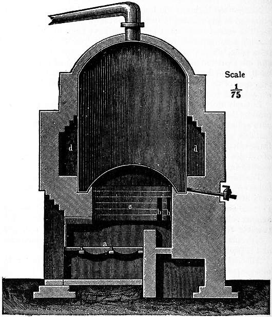
Fig. 1.—Tar-Still (sectional elevation).1
Tar-Stills.—The tar is now pumped into the tar-still, fig. 1. This is usually, as shown, an upright wrought-iron cylinder, with an arched top, and with a bottom equally vaulted upwards for the purpose of increasing the heating surface and of raising the level of the pitch remaining at the end of the operation above the fire-flues. The fuel is consumed on the fire-grate a, and, after having traversed the holes bb in the annular wall e built below the still, the furnace gases are led around the still by means of the flue d, whence they pass to the chimney. Cast-iron necks are provided in the top for the outlet of the vapours, for a man-hole, supply-pipe, thermometer-pipe, safety valve, and for air and steam-pipes reaching down to the bottom and branching out into a number of distributing arms. Near the top there is an overflow pipe which comes into action on filling the still. In the lowest part of the bottom there is a running-off valve or tap. In some cases (but only exceptionally) a perpendicular shaft is provided, with horizontal arms, and chains hanging down from these drag along the bottom for the purpose of keeping it clean and of facilitating the escape of the vapours. This arrangement is quite unnecessary where the removal of the vapours is promoted by the injection of steam, but this steam must be carefully dried beforehand, or, better, slightly superheated, in order to prevent explosions, which might be caused by the entry of liquid water into the tar during the later stages of the work, when the temperature has arisen far above the boiling-point of water. The steam acts both by stirring up the tar and by rapidly carrying off the vapours formed in distillation. The latter object is even more thoroughly attained by the application of a vacuum, especially during the later stage of distillation. For this purpose the receivers, in which the liquids condensed in the cooler are collected, are connected with an air pump or an ejector, by which a vacuum of about 4 in., say 1⁄8 atmosphere, is made which lowers the boiling process by about 80° C.; this not merely hastens the process, but also produces an improvement of the quality and yield of the products, especially of the anthracene, and, moreover, lessens or altogether prevents the formation of coke on the still-bottom, which is otherwise very troublesome.
Most manufacturers employ ordinary stills as described. A few of them have introduced continuously acting stills, of which that constructed by Frederic Lennard has probably found a wider application than any of the others. They all work on the principle of gradually heating the tar in several compartments, following one after the other. The fresh tar is run in at one end and the pitch is run out from the other. The vapours formed in the various compartments are separately carried away and condensed, yielding at one and the same time those products which are obtained in the ordinary stills at the different periods of the distillation. Although in theory this continuous process has great advantages over the ordinary style of working, the complication of the apparatus and practical difficulties arising in the manipulation have deterred most manufacturers from introducing it.
The tar-stills are set in brickwork in such a manner that there is no over-heating of their contents. For this purpose the fire-grate is placed at a good distance from the bottom or even covered by a brick arch so that the flame does not touch the still-bottom at all and acts only indirectly, but the sides of the still are always directly heated. The fire-flue must not be carried up to a greater height than is necessary to provide against the overheating of any part of the still not protected inside by liquid tar, or, at the end of the operation, by liquid pitch. The outlet pipe is equally protected against overheating and also against any stoppage by pitch solidifying therein. The capacity of tar-stills ranges from 5 to 50 tons. They hold usually about 10 tons, in which case they can be worked off during one day.
The vapours coming from the still are condensed in coolers of various shapes, one of which is shown in figs. 2 and 3. The cooling-pipes are best made of cast-iron, say 4 in. wide inside and laid so as to have a continuous fall towards the bottom. A steam-pipe (b) is provided for heating the cooling water, which is necessary during the later part of the operation to prevent the stopping up of the pipes by the solidification of the distillates. A cock (a) allows steam to be injected into the condensing worm in order to clear any obstruction.

Fig. 2.—Condensing Worm (Plan)
The cooling-pipe is at its lower end connected with receivers for the various distillates in such a manner that by the turning of a cock the flow of the distillates into the receivers can be changed at will. In a suitable place provision is made for watching the colour, the specific gravity, and the general appearance of the distillates. At the end of the train of apparatus, and behind the vacuum pump or ejector, when one is provided, there is sometimes a purifier for the gases which remain after condensation; or these gases are carried back into the fire, in which case a water-trap must be interposed to prevent explosions.
Distillation of the Tar.—The number of fractions taken during the distillation varies from four to six. Sometimes a first fraction is taken as “first runnings,” up to a temperature of 105° C. in the still, and a second fraction as “light oil,” up to 210° C., but more usually these two are not separated in the first distillation, and the first or “light oil” fraction then embraces everything which comes over until the drops no longer float on, but show the same specific gravity as water. The specific gravity of this fraction varies from 0.91 to 0.94. The next fraction is the “middle oil” or “carbolic oil,” of specific gravity 1.01, boiling up to 240° C.; it contains most of the carbolic acid and naphthalene. The next fraction is the “heavy oil” or “creosote oil,” of specific gravity 1.04. Where the nature of the coals distilled for gas is such that the tar contains too little anthracene to be economically recovered, the creosote-oil fraction is carried right to the end; but otherwise, that is in most cases, a last fraction is made at about the temperature 270° C., above which the “anthracene oil” or “green oil” is obtained up to the finish of the distillation.
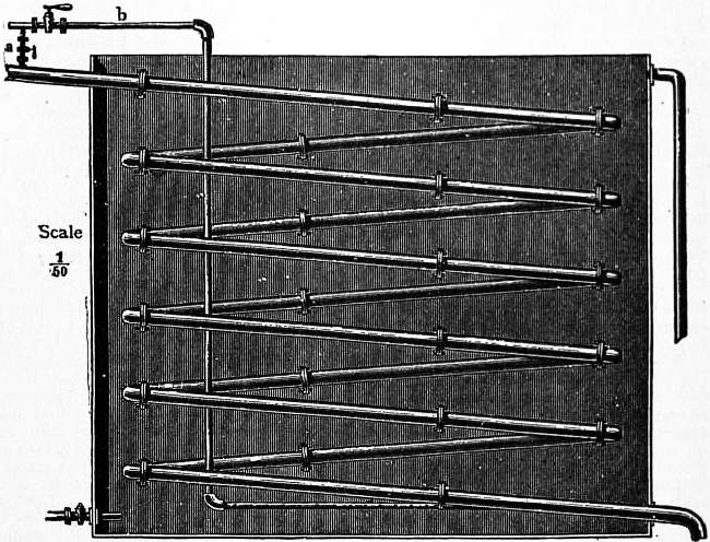
Fig. 3.—Condensing Worm (side elevation).
During the light-oil period the firing must be performed very cautiously, especially where the water has not been well removed, to prevent bumping and boiling over. It has been observed that, apart from the water, those tars incline most to boiling over which contain an unusual quantity of “fixed carbon.” During this period cold water must be kept running through the cooler. The distillate at once separates into water (gas-liquor) and light oil, floating at the top. Towards the end of this fraction the distillation seems to cease, in spite of increasing the fires, and a rattling noise is heard in the still. This is caused by the combined water splitting off from the bases and phenols and causing slight explosions in the tar.
As soon as the specific gravity approaches 1.0, the supply of cold water to the cooler is at least partly cut off, so that the temperature of the water rises up to 40° C. This is necessary because otherwise some naphthalene would crystallize out and plug up the pipes. If a little steam is injected into the still during this period no stoppage of the pipes need be feared in any case, but this must be done cautiously.
When the carbolic oil has passed over and the temperature in the still has risen to about 240° C., the distillate can be run freely by always keeping the temperature in the cooler at least up to 40° C. The “creosote oil” which now comes over often separates a good deal of solid naphthalene on cooling.
The last fraction is made, either when the thermometer indicates 270° C., or when “green grease” appears in the distillate, or simply by judging from the quantity of the distillate. What comes over now is the “anthracene oil.” The firing may cease towards the end as the steam (with the vacuum) will finish the work by itself. The water in the cooler should now approach the boiling-point.
The point of finishing the distillation is different in various places and for various objects. It depends upon the fact whether soft or hard pitch is wanted. The latter must be made where it has to be sold at a distance, as soft pitch cannot be easily carried during the warmer season in railway trucks and not at all in ships, where it would run into a single lump. Hard pitch is also always made where as much anthracene as possible is to be obtained. For hard pitch the distillation is carried on as far as practicable without causing the residue in the still to “coke.” The end cannot be judged by the thermometer, but by the appearance and quantity of the distillate and its specific gravity. If carried too far, not merely is coke formed, but the pitch is porous and almost useless, and the anthracene oil is contaminated with high-boiling hydrocarbons which may render it almost worthless as well. Hard pitch proper should soften at 100° C., or little above.
Where the distillation is to stop at soft pitch it is, of course, not carried up to the same point, but wherever the pitch can be disposed of during the colder season or without a long carriage, even the hard pitch is preferably softened within the still by pumping back a sufficient quantity of heavy oil, previously deprived of anthracene. This makes it much easier to discharge the still. When the contents consist of soft pitch they are run off without much trouble, but hard pitch not merely emits extremely pungent vapours, but is mostly at so high a temperature that it takes fire in the air. Hard pitch must, therefore, always be run into an iron or brick cooler where it cools down out of contact with air, until it can be drawn out into the open pots where its solidification is completed.
Most of the pitch is used for the manufacture of “briquettes” (“patent fuel”), for which purpose it should soften between 55° and 80° C. according to the requirements of the buyer. In Germany upwards of 50,000 tons are used annually in that industry; much of it is imported from the United Kingdom, whence also France and Belgium are provided. Apart from the softening point the pitch is all the more valued the more constituents it contains which are soluble in xylene. The portion insoluble in this is denoted as “fixed carbon.” If the briquette manufacturer has bought the pitch in the hard state he must himself bring it down to the proper softening point by re-melting it with heavy coal-tar oils.
We now come to the treatment of the various fractions obtained from the tar-stills. These operations are frequently not carried out at the smaller tar-works, which sell their oils in the crude state to the larger tar-distillers.
Working up of the Light-Oil Fraction.—The greatest portion of the light-oil fraction consists of aromatic hydrocarbons, about one-fifth being naphthalene, four-fifths benzene and its homologues, in the proportion of about 100 benzene, 30 toluene, 15 xylenes, 10 trimethylbenzenes, 1 tetramethylbenzene. Besides these the light-oil contains 5-15% phenols, 1-3% bases, 0.1 sulphuretted compounds, 0.2-0.3% nitriles, &c. It is usually first submitted to a preliminary distillation in directly fired stills, similar to the tar-stills, but with a dephlegmating head. Here we obtain (1) first runnings (up to O.89 spec. grav.), (2) heavy benzols (up to O.95), (3) carbolic oil (up to 1.00). The residue remaining in the still (chiefly naphthalene) goes to the middle-oil fraction.
The “first runnings” are now “washed” in various ways, of which we shall describe one of the best. The oil is mixed with dilute caustic soda solution, and the solution of phenols thus obtained is worked up with that obtained from the next fractions. After this follows a treatment with dilute sulphuric acid (spec. grav. 1.3), to extract the pyridine bases, and lastly with concentrated sulphuric acid (1.84), which removes some of the aliphatic hydrocarbons and “unsaturated” compounds. After this the crude benzol is thoroughly washed with water and dilute caustic soda solution, until its reaction is neutral. The mixing of the basic, acid and aqueous washing-liquids with the oils is performed by compressed air, or more suitably by mechanical stirrers, arranged on a perpendicular, or better, a horizontal shaft. Precisely the same treatment takes place with the next fraction, the “heavy benzols,” and the oils left behind after the washing operations now go to the steam-stills. The heaviest hydrocarbons are sometimes twice subjected to the operation of washing.
The washed crude benzols are now further fractionated by distillation with steam. The steam-stills are in nearly all details on the principle of the “column apparatus” employed in the distillation of alcoholic liquids, as represented in fig. 4. They are usually made of cast iron. The still itself is either an upright or a horizontal cylinder, heated by a steam-coil, of a capacity of from 1000 to 2000 gallons. The superposed columns contain from 20 to 50 compartments of a width of 2½ or 3 ft. The vapours pass into a cooler, and from this the distillate runs through an apparatus, where the liquor can be seen and tested, into the receivers. The latter are so arranged that the water passing over at the same time is automatically removed. This is especially necessary, because the last fraction is distilled by means of pure steam.
The fractions made in the steam distillation vary at different works. In some places the pure hydrocarbons are net extracted and here only the articles called: “90 per cent. benzol,” “50 per cent. benzol,” “solvent naphtha,” “burning naphtha” are made, or any other commercial articles as they are ordered. The expression “per cent.” in this case does not signify the percentage of real benzene, but that portion which distills over up to the temperature of 100° C., when a certain quantity of the article is heated in glass retorts of a definite shape, with the thermometer inserted in the liquid itself. By the application of well-constructed rectifying-columns and with proper care it is, however, possible to obtain in this operation nearly pure benzene, toluene, xylene, and cumene (in the two last cases a mixture of the various isomeric hydrocarbons). These hydrocarbons contain only a slight proportion of thiophene and its isomers, which can be removed only by a treatment with fuming sulphuric acid, but this is only exceptionally done.
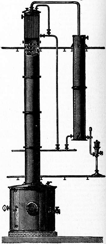
Fig. 4.—Benzol Still (elevation).
Sometimes the pyridine bases are recovered from the tarry acid which is obtained in the treatment of the light oil with sulphuric acid, and which contains from 10 to 30% of bases, chiefly pyridine and its homologues with a little aniline, together with resinous substances. The latter are best removed by a partial precipitation with ammonia, either in the shape of gas or of concentrated ammoniacal liquor. This reagent is added until the acid reaction has just disappeared and a faint smell of pyridine is perceived. The mixture is allowed to settle, and it then separates into two layers. The upper layer, containing the impurities, is run off; the lower layer, containing the sulphates of ammonia and of the pyridine bases, is treated with ammonia in excess, where it separates into a lower aqueous layer of ammonium sulphate solution and an oil, consisting of crude pyridine. This is purified by fractionation in iron stills and distillation over caustic soda. Most of it is used for denaturing spirit of wine in Germany, for which purpose it is required to contain 90% of bases boiling up to 140° C. (see Alcohol).
Working up of the Middle-Oil Fraction (Carbolic Oil Fraction).—Owing to its great percentage of naphthalene (about 40%) this fraction is solid or semi-solid at ordinary temperatures. Its specific gravity is about 1.2; its colour may vary from light yellow to dark brown or black. In the latter case it must be re-distilled before further treatment. On cooling down, about four-fifths of the naphthalene crystallizes out on standing from three to ten days. The crystals are freed from the mother oils by draining and cold or hot pressing; they are then washed at 100° C. with concentrated sulphuric acid, afterwards with water and re-distilled or sublimed. About 10,000 tons of naphthalene are used annually in Germany, mostly for the manufacture of many azo-colours and of synthetic indigo.
The oils drained from the crude naphthalene are re-distilled and worked for carbolic acid and its isomers. For this purpose the oil is washed with a solution of caustic soda, of specific gravity 1.1; the solution thus obtained is treated with sulphuric acid or with carbon dioxide, and the crude phenols now separated are fractionated in a similar manner as is done in the case of crude benzol. The pure phenol crystallizes out and is again distilled in iron stills with a silver head and cooling worm; the remaining oils, consisting mainly of cresols, are sold as “liquid carbolic acid” or under other names.
Most of the oil which passes as the “creosote-oil fraction” is sold in the crude state for the purpose of pickling timber. It is at the ordinary temperature a semi-solid mixture of about 20% crystallized hydrocarbons (chiefly naphthalene), and 80% of a dark brown, nauseous smelling oil, of 1.04 spec. grav., and boiling between 200° and 300° C. The liquid portion contains phenols, bases, and a great number of hydrocarbons. Sometimes it is redistilled, when most of the naphthalene passes over in the first fraction, between 180° and 230° C., and crystallizes out in a nearly pure state. The oily portion remaining behind, about 60% of this distillate, contains about 30% phenols and 3% bases. It has highly disinfectant properties and is frequently converted into special disinfectants, e.g. by mixing it with four times its volume of slaked lime, which yields “disinfectant powder” for stables, railway cars, &c. Mixtures of potash soaps (soft soaps) with this oil have the property of yielding with water emulsions which do not settle for a long time and are found in the trade as “creolin,” “sapocarbol,” “lysol,” &c.
That description of creosote oil which is sold for the purpose of pickling railway sleepers, telegraph posts, timber for the erection of wharves and so forth, must satisfy special requirements which are laid down in the specifications for tenders to public bodies. These vary to a considerable extent. They always stipulate (1) a certain specific gravity (e.g. not below 1.035 and not above 1.065); (2) certain limits of boiling points (e.g. to yield at most 3% up to 150°, at most 30% between 150° and 255°, and at least 85% between 150° and 355°); (3) a certain percentage of phenols, as shown by extraction with caustic soda solution, say 8 to 10%.
Much of this creosote oil is obtained by mixing that which has resulted in the direct distillation of the tar with the liquid portion of the anthracene oils after separating the crude anthracene (see below). It is frequently stipulated that the oil should remain clear at the ordinary temperature, say 15° C., which means that no naphthalene should crystallize out.
Working up the Anthracene Oil Fraction.—The crude oil boils between 280° and 400° C. It is liquid at 60° C., but on cooling about 6 to 10% of crude anthracene separates as greenish-yellow, sandy crystals, containing about 30% of real anthracene, together with a large percentage of carbazol and phenanthrene. This crystallization takes about a week. The crude anthracene is separated from the mother oils by filter presses, followed by centrifugals or by hot hydraulic presses. The liquid oils are redistilled, in order to obtain more anthracene, and the last oils go back to the creosote oil, or are employed for softening the hard pitch (vide supra). The crude anthracene is brought up to 50 or 60, sometimes to 80%, by washing with solvent naphtha, or more efficiently with the higher boiling portion of the pyridine bases. The naphtha removes mostly only the phenanthrene, but the carbazol can be removed only by pyridine, or by subliming or distilling the anthracene over caustic potash. The whole of the anthracene is sold for the manufacture of artificial alizarine.
Bibliography.—The principal work on Coal-tar is G. Lunge’s Coal-tar and Ammonia (3rd ed., 1900). Consult also G. P. Sadtler, Handbook of Industrial Organic Chemistry (1891), and the article “Steinkohlentheer,” Kraemer and Spreker, in Encyklopädisches Handbuch der technischen Chemie (4th ed., 1905, viii. 1).
(G. L.)
COALVILLE, a town in the Loughborough parliamentary division of Leicestershire, England, 112 m. N.N.W. from London. Pop. of urban district (1901) 15,281. It is served by the Midland railway, and there is also a station (Coalville East) on the Nuneaton-Loughborough branch of the London & North-Western railway. This is a town of modern growth, a centre of the coal-mining district of north Leicestershire. There are also iron foundries and brick-works. A mile north of Coalville is Whitwick, with remains of a castle of Norman date, while to the north again are slight remains of the nunnery of Gracedieu, founded in 1240, where, after its dissolution, Francis Beaumont, the poet-colleague of John Fletcher, was born about 1586. In the neighbourhood is the Trappist abbey of Mount St Bernard, founded in 1835, possessing a large domain, with buildings completed from the designs of A. W. Pugin in 1844.
COAST (from Lat. costa, a rib, side), the part of the land which meets the sea in a line of more or less regular form. The word is sometimes applied to the bank of a river or lake, and sometimes to a region (cf. Gold Coast, Coromandel Coast) which may include the hinterland. If the coast-line runs parallel to a mountain range, such as the Andes, it has usually a more regular form than when, as in the rias coast of west Brittany, it crosses the crustal folds. Again, a recently elevated coast is more regular than one that has been long exposed to wave action. A recently depressed coast will show the irregularities that were impressed upon the surface before submergence. Wave erosion and the action of marine currents are the chief agents in coast sculpture. A coast of homogeneous rock exposed to similar action will present a regular outline, but if exposed to differential action it will be embayed where that action is greatest. A coast consisting of rocks of unequal hardness or of unequal structure will present headlands, “stacks” and “needles” of hard rocks, and bays of softer or more loosely aggregated rocks, when the wave and current action is similar throughout. The southern shore-line of the Isle of Wight and the western coast of Wales are simple examples of this differential resistance. In time the coast becomes “mature” and its outline undergoes little change as it gradually recedes, for the hard rock being now more exposed is worn away faster, but the softer rock more slowly because it is protected in the bays and re-entrants.
COAST DEFENCE, a general term for the military and naval protection and defence of a coast-line, harbours, dockyards, coaling-stations, &c., against serious attack by a strong naval force of the enemy, bombardment, torpedo boat or destroyer raids, hostile landing parties, or invasion by a large or small army. The principal means employed by the defender to cope with these and other forms of attack which may be expected in time of war or political crisis are described below. See also for further details Navy; Army; Fortification and Siege-craft; Ammunition; Ordnance; Submarine Mines; Torpedo. The following is a general description of modern coast defences as applied in the British service.
No system of coast defence is of any value which does not take full account of the general distribution of sea-power and the resultant strength of the possible hostile forces. By resultant strength is meant the balance of one side over the other, for it is now generally regarded as an axiom that two opposing fleets must make their main effort in seeking one another, and that the force available for attack on coast defences will be either composed of such ships as can be spared from the main engagement, or the remnant of the hostile fleet after it has been victorious in a general action.
Coast defences are thus the complement and to some extent the measure of naval strength. It is often assumed that this principle was neglected in the large scheme of fortification associated in England with the name of Lord Palmerston, but it is at least arguable that the engineers responsible for the details of this scheme were dependent then as now on the naval view of what was a suitable naval strength. Public opinion has since been educated to a better appreciation of the necessity for a strong navy, and, as the British navy has increased, the scale of coast defences required has necessarily waned. Such a change of opinion is always gradual, and it is difficult to name an exact date on which it may be said that modern coast defence, as practised by British engineers, first began.
An approximation may, however, be made by taking the bombardment of Alexandria (1881) as being the parting of the ways between the old and the modern school. At that time the British navy, and in fact all other navies, had not really emerged from the stage of the wooden battleships. Guns were still muzzle-loaders, arranged mainly in broadsides, and protected by heavy armour; sails were still used as means of propulsion; torpedoes, net defence, signalling, and search-lights quite undeveloped.
At this time coast defences bore a close resemblance to the ships—the guns were muzzle-loaders, arranged in long batteries like a broadside, often in two tiers. The improvement of rifled ordnance had called for increased protection, and this was found first by solid constructions of granite, and latterly by massive iron fronts. Examples of these remain in Garrison Fort, Sheerness, and in Hurst Castle at the west end of the Solent. The range of guns being then relatively short, it was necessary to place forts at fairly close intervals, and where the channels to be defended could not be spanned from the shore, massive structures with two or even three tiers of guns, placed as close as on board ship and behind heavy armour, were built up from the ocean bed. On both sides the calibre and weight of guns were increasing, till the enormous sizes of 80 and 100 tons were used both ashore and afloat.
The bombardment of Alexandria established two new principles, or new applications of old principles, by showing the value of concealment and dispersion in reducing the effect of the fire of the fleet. On the old system, two ships firing at one another or ships firing at an iron-fronted fort shot “mainly into the brown”; if they missed the gun aimed at, one to the right or left was likely to be hit; if they missed the water-line, the upper works were in danger. At Alexandria, however, the Egyptian guns were scattered over a long line of shore, and it was soon found that with the guns and gunners available, hits could only be obtained by running in to short range and dealing with one gun at a time.
This new principle was not at once recognized, for systems die hard, and much money and brains were invested in the then existing system. But a modern school was gradually formed; a small group of engineer officers under the headship of Sir Andrew Clarke, the then inspector-general of fortifications, took the matter up, and by degrees the new views prevailed and the modern school of coast defence came into being between 1881 and 1885. Meanwhile important changes had been developing in the gun, the all-important weapon of coast defence, changes due mainly to the gradual supersession of the muzzle-loader by the breech-loader. The latter gave the advantages of quicker loading and more protection for the gun detachment over and above the technical improvements in the gun itself, which gave higher muzzle velocity, greater striking effect and longer effective range.
All this reacted on the general scheme of coast defence by enabling the number of guns to be reduced and the distance between forts increased. On the other hand, the ships, too, gained increased range and increased accuracy of fire, so that it became necessary in many cases to advance the general line of the coast defences farther from the harbour or dockyard to be defended, in order to keep the attackers out of range of the objective.
Another change resulted from an improvement in the method of mounting. Even in the older days discussion had arisen freely on the relative merits of barbette and casemate mounting. In the former the gun fires over a parapet, giving a larger field of view to the gun-layer, and a larger field of fire for the gun, with, however, more exposure for the detachment. The latter gives a restricted view and greater safety to the layer, but unless the casemate takes the form of a revolving turret, the arc of fire is very limited.
An important advantage of the barbette system is its cheapness, and thus in order to obtain with it concealment, suggestions were made for various forms of mounting which would allow of the gun, under the shock of recoil, disappearing behind the parapet to emerge only when loaded and ready for the next round. A mounting of this description for muzzle-loading guns, designed by Colonel Moncrieff, was actually in use in the defences of Alexandria and in H.M.S. “Téméraire.”
But with the increased charges and length of breech-loading guns, a further change was desirable, and after some trials a system of disappearing mountings (see Ordnance: Garrison Mountings) was adopted into the British service.
A word must be now said on the size of gun finally adopted. At first muzzle-loaders figured largely in the British defences, even though these were planned on modern ideas; and even in 1906 muzzle-loading guns still existed and were counted as part of the defences. The sizes of these guns varied from the 32- or 64-pounder, of which the nomenclature depends on the weight of the shell, to the 7-in., 9-in., 10-in., 11-in., 12.5- and finally 17.25-in., the size indicating the calibre. Such a multiplication of sizes was due to gradual improvements in the science of gun manufacture, each advance being hailed as the last word to be said on the subject, and each in turn being rapidly made obsolete by something bigger and better. But with the improvements in gun design which followed the introduction of breech-loaders, the types used in coast defence were gradually narrowed down to two, the 9.2-in. and the 6-in. guns. Of these, the 9.2-in. was considered powerful enough to attack armour at any practical range, while the 6-in. gun was introduced to deal with lightly armed vessels at shorter ranges where 9.2-in. guns were unnecessarily powerful.
A few larger guns of 10-in. calibre have actually been used, but though the British navy has now sealed a 12-in. 50-ton gun as the stock size for battleships, for the heavy armament of the coast defences the War Office remain faithful to the 9.2-in. calibre, preferring to develop improvements rather in the direction of more rapid fire and higher muzzle velocity.
The 6-in. has also been retained and is extensively used for the smaller ports, where attack by powerful vessels is for various reasons considered improbable.
The design of the forts to contain the guns necessarily varied with the type of defence adopted, and the duties which the forts had to fulfil. These duties may be said to be twofold, first to facilitate the service of the guns, and secondly to protect the guns and their detachments from damage by fire from ships, or by close attack from landing parties. The service of the gun is provided for by a system of cartridge and shell magazines (see Ammunition), well protected from fire and suitably arranged. The shelters for the gun detachments must be bomb-proof and fitted with some arrangements for comfort and sanitation. Formerly it was the custom to provide living accommodation for the full garrison in casemates inside each fort, but it is now considered better to provide barrack accommodation in the vicinity and to occupy forts in peace only by a few caretakers. The shelters in the fort itself can thus be kept at the minimum required when actually manning the guns. The protection of the guns and magazines against bombardment is provided, in the British service, mainly by an earthen parapet over a substantial roof or wall of concrete, but immediately round the gun an “apron” of concrete is necessary to withstand the shock of discharge or “blast.”
It has been already mentioned that in the old designs a large number of guns was put in each fort, but with dispersion and improved gun power this number was much reduced. At first the type of fort adopted was for four guns, of which the two in the centre were heavy and the two on the flank of medium power. Such a design was good from the point of view of the engineer; it gave an economical grouping of magazines and shelters and was easily adapted to varying sites, and the smaller guns helped the larger by covering their flanks both towards the sea and also over the land approaches. But from the point of view of the artillery officer the arrangement was faulty, for when the guns are too much separated, ranging has to be carried out separately for each gun. On the other hand, two guns of the same calibre placed near one another can be fought simultaneously and form what is known as a “group.” In the typical 4-gun battery described above, the flank guns had to be fought independently, which was wasteful of officers and staff. Further, in a battery of more than two guns the arc of fire of the centre guns is much restricted by that of the guns on either flank.
For these reasons it is now generally recognized that new works should be designed for only two guns of the same calibre, though 3- or 4-gun batteries are occasionally used in special circumstances.
Protection of the gun detachments against infantry attack is best provided by a line of infantry posts outside and on the flanks of the gun batteries, but as small parties may evade the outposts, or the latter may be driven in, it is necessary to place round each fort a line of obstacles sufficient to protect the guns against a rush and to cover the infantry while it rallies. This obstacle was formerly a wet or dry ditch, with escarp, counterscarp and flanking galleries; but with the new design of parapet a simpler form of obstacle was adopted. This was obtained by carrying down and forward the slope of the parapet to a point well below the level of the surrounding ground, and then placing a stout fence at the foot of the parapet and concealed from view. It is in fact the old principle of the sunk fence, and has this further advantage, that the fence, being visible from the parapet, can be kept under fire by men posted between the guns without any special flanking galleries.
Occasionally two or more batteries are placed inside one line of obstacles, but usually each 2-gun battery is complete in itself.
Cases arise, e.g. with sites on the top of a cliff, where no obstacle is required; in such places the parapet merges into the surrounding ground.
In old days the parapet was shaped with well-defined edges and slopes. Now the parapet slopes gently down to the front and is rounded at the sides, so as to present no definite edge or angle to the enemy, and concealment is furthered by allowing grass or small scrub to grow over the parapet and round the guns. In order to obtain complete concealment from view the background behind the guns must be carefully studied from the point of view of the attack. Sites on the sky-line, and marked contrasts of colour or shape, should be avoided. In some cases extensive planting, amounting to landscape gardening, is justified. This is most easily arranged in the tropics, where plant growth is rapid. In all cases the guns and their mountings should be coloured to blend with the background and thus avoid hard lines and shadows.
Any change of principle such as that of 1885 involves improvements both in guns and their adjuncts. Of these latter the most important was the position-finder designed by Colonel Watkin. This instrument in its simplest form, when the observer is following a ship through the telescope of the instrument, draws on a chart the track of the ship, so that the exact bearing and distance of the latter can be ascertained at any time and communicated to the guns by electrical and other dials, &c. The position-finder may be some distance from the guns it serves, and connected with them by electric cable. The guns can then be placed well under cover and in many cases out of sight of the target, giving a measure of protection which cannot be obtained with any system of direct laying over sights. This instrument has been applied on a high site to control guns placed low, or where guns are so placed as to be liable to obscuration by fog or mist the position-finder can be placed below the fog-line. In either case direct laying is provided for as an alternative. In some defences batteries equipped with old pattern 9-in. muzzle-loading guns, mounted as howitzers for long-range firing, have been placed in folds in the ground so as to be quite invisible from the sea and therefore invulnerable. Such batteries are fought entirely by the position-finder.
The next adjunct to coast defences is the submarine mine. In Great Britain the first submarine mining company dates from 1873, and from that date mining defences were gradually installed both at home and abroad; but the modern system of mining, which for twenty years was maintained at British ports, really started into full life under the impetus of Sir A. Clarke, about the same year (1885) in which we have dated the commencement of the modern coast defence system.
With the increased speed of warships, a method of attack on fortifications was evolved by running past the main defences and either taking them in reverse, or disregarding them and attacking the dockyard or other objective at short range. This was made more possible at most defended ports by the pushing forward of the defences which has been already alluded to, and it is especially dangerous where dockyards or towns are situated some way up a river or estuary, so that once the defences are passed there is a large stretch of water (e.g. the Thames, the Solent, and Cork harbour) in which the enemy can manoeuvre. In such cases there are two possible forms of defence, first by arranging for gun-fire behind the main gun position, usually called the defence of inner waters, and secondly by placing in the entrance and under the fire of the main gun defence some form of obstruction to detain ships under fire. This obstruction can be passive (booms, chains, rows of piles or sunken ships) or active (mines or torpedoes). Passive obstructions are only effective against comparatively small craft, and at important ports mines are the only efficient obstruction which can be used against large vessels.
After some years of experiment, English engineers adopted two main classes of mines, called “observation” and “contact” mines (see Submarine Mines). Both were fired by electricity, which was applied only at the moment a hostile ship was within the dangerous zone of a mine. In the observation mines the moment of applying the electric current was ascertained by a position-finder, which, tracing a ship’s course on a chart, made an electrical connexion at the moment the ship was over a mine. These mines were placed so as to be well below the bottom of any ships afloat and were used in channels which it was desired to leave open for the entrance of friendly vessels. Contact mines, which are moored a few feet below the surface of the water, are fired after certain electrical connexions have been made in a firing room on shore by the ship itself striking against the mine. These are used in waters which it is intended to deny to friend and foe. Except in narrow waters where the whole width of the channel was required for friendly traffic, contact mines were generally used to limit the width of the channel to the minimum consistent with the amount of friendly traffic which would use the port in war. It will be readily understood that by bending this channel and disclosing its exact position only to special pilots, a very complete measure of security against surprise would be obtained. In English ports the practical importance of allowing free ingress for friendly traffic overruled all other considerations, and the friendly channels were always straight and coincided with some part of the usual fairway channel. They were also carefully marked by lightships and buoys.
A variation of the submarine mine is the Brennan torpedo, purchased by the British government about 1890. This differs from the torpedo used on board ship, mainly by the fact that the engine-power which drives it is on shore and connected with the torpedo by two strong wires. These wires are wound out of the torpedo by the engine, and by varying the strain on the two wires very accurate control of the steering can be obtained. This torpedo shares with the submarine mine the disadvantages that it must wait for the enemy to venture within its range, and with all other forms of defence (except contact mines), that it is made useless by fog or rain. As compared with a mine it has the advantage of being unaffected by tide or depth, and of forming no obstruction to traffic, except when actually in action. It was installed at the principal ports only.
The system of defence hitherto described is thus a main gun defence of 9.2-in. and 6-in. guns pushed well forward, assisted by position-finders, mine-fields and torpedo stations, and with some gun defence of inner waters. Subject to improvements in patterns of guns and mountings—of which the most important has been the substitution of barbette mounting and shield for the recoil mounting described above—this system held the field up to 1905, when, partly as a result of the experience of the Russo-Japanese War, and partly owing to the alteration of the naval balance of power due to the destruction of the Russian fleet, both the scale and system of defence were very considerably modified.
We can now consider another branch of defence, which was evolved pari passu with the automobile torpedo, and was therefore almost non-existent in 1885. In this year the boats specially built for carrying torpedoes were little more than launches, but in the next five years was developed the type of first-class torpedo boat. This, while seaworthy, was limited as to its radius of action by the small amount of coal it would carry. But with a possibly hostile coast only a few hours’ steam away, and with foreign harbours thronged with torpedo craft, it became necessary for the British government especially to consider this form of attack and its antidote. It was obvious that in daytime and in clear weather such an attack would have little chance of success, also that in no circumstances would torpedo boats be able to damage fixed defences. Their best chance was attack by night, and the only form of attack was that referred to above as “running past,” that is, an attempt to evade the defences and to attack ships or docks inside. The light draught of torpedo boats and their comparative invisibility favoured this form of attack.
To meet it the first requirement was some form of illumination of the defended channel. Experiments in the attack and defence of defended harbours took place at Gosport in 1879 and 1880, at Milford Haven in 1885, at Berehaven (by the royal navy) in 1886, at Langston Harbour in 1887, and a series at the Needles entrance of the Isle of Wight up to 1892. During the course of these experiments various methods of illumination were tried, but by far the best was found to be the light from an electric arc-lamp of high power projected by powerful reflectors. At first these were used as concentrated beams forming a pencil of light with an angular opening of about 2° to 3°. Such a beam directed at an incoming ship gives effective illumination up to a mile or more from the source of light, but has the disadvantage that it must be moved so as to follow the ship’s movements. Each beam thus lights only one ship at a time, and the movements of several beams crossing and recrossing have a very confusing effect, with the consequent risk that a proportion of the attacking vessels may slip through unnoticed.
An alternative method of using electric lights is to arrange the projector so that the light comes out in a fan (generally of 30° divergence). Two or three such lights are usually placed side by side, forming an illuminated fan of considerable divergence. These fans are now used for the main defence, with in front of them one or more search-lights to warn the defences of the approach of ships. There is some loss of range when using these fans as compared with search-lights, but by occupying both sides of a channel and placing the defences against torpedo boats at the narrowest point, an effective illumination can be obtained in moderate weather.
Heavy guns can, of course, be fired against torpedo boats, but their rate of fire is relatively slow, and at first they had also the disadvantage of using black powder, the smoke of which obscured the lights.
A small quick-firing gun using smokeless powder was seen to be a necessity. At first the 6-pounder was adopted as the stock size supplemented by machine guns for close range, but soon afterwards it became necessary to reconsider the scale of anti-torpedo boat defences, owing first to the increased size of first-class torpedo boats, and secondly to the introduction of a new type of vessel, the torpedo boat destroyer. The increased size of torpedo boats, and improved arrangements for the distribution of coal on board, made these boats practically proof against 6-pounder guns and necessitated the introduction of the 12-pounder. The torpedo boat destroyer, originally introduced to chase and destroy torpedo boats, not only justified its existence by checking the construction of more torpedo boats, but in addition became itself a sea-going torpedo craft, and thus increased the menace to defended ports and also the area over which this form of attack would be dangerous.
This development was met by an increased number of 12-pounder guns, assisted in the more important places by 4.7-in. (and latterly 4-in.) guns, and also by an increased number of lights, both guns and lights increasing at some places nearly fourfold. But even with the best possible arrangement of this form of defence, the possibility of interference by fog, mist or rain introduces a considerable element of uncertainty.
About the same time, and largely on account of the demand for better and quicker firing, the “automatic sight” was introduced (see Ordnance: Garrison; and Sights). In this, a development of the principle of the position-finder, the act of bringing an object into the field of the auto-sight automatically lays the gun. In order to take full advantage of this, the ammunition was made up into a cartridge with powder and shell in one case to allow of the quickest possible loading. It may be added that the efficiency of the auto-sight depends on the gun being a certain height above the water, and that therefore the rise and fall of tide has to be allowed for in setting the sight.
In view of the possible interference by fog it was thought wise at an early stage to provide, towards the rear of the defences, some form of physical obstacle behind which ships could lie in safety. Such an obstacle had been designed in the early days by the Royal Engineers and took the form of a “boom” of baulks of timber secured by chains. Such booms were limited in size by considerations of expense and were only partially successful. About 1892 the British navy took the matter up and began experiments on a larger scale, substituting wire hawsers for chains and using old gunboats to divide the booms up into sections of convenient length. The result was that booms were definitely adopted as an adjunct of coast defence. Their place is behind the lighted area, but within reach of some of the anti-torpedo boat batteries.