VOLUME VI SLICE V Clervaux to Cockade (continued 4)
Reading edition
What he had done for Madras, what he had accomplished for Bengal proper, and what he had effected in reforming the Company itself, he was now to complete in less than two years, in this the third period of his career, by putting his country politically in the place of the emperor of Delhi, and preventing for ever the possibility of the corruption to which the British in India had been driven by an evil system. On the 3rd of May 1765 he landed at Calcutta to learn that Jafar Ali Khan had died, leaving him personally £70,000, and had been succeeded by his son, though not before the government had been further demoralized by taking £100,000 as a gift from the new nawab; while Kasim Ali had induced not only the viceroy of Oudh, but the emperor of Delhi himself, to invade Behar. After the first mutiny in the Bengal army, which was suppressed by blowing the sepoy ringleader from a gun, Major Munro, “the Napier of those times,” scattered the united armies on the hard-fought field of Buxar. The emperor, Shah Alam, detached himself from the league, while the Oudh viceroy threw himself on the mercy of the British. Clive had now an opportunity of repeating in Hindustan, or Upper India, what he had accomplished for the good of Bengal. He might have secured what are now called the United Provinces, and have rendered unnecessary the campaigns of Wellesley and Lake. But he had other work in the consolidation of rich Bengal itself, making it a base from which the mighty fabric of British India could afterwards steadily and proportionally grow. Hence he returned to the Oudh viceroy all his territory save the provinces of Allahabad and Kora, which he made over to the weak emperor. But from that emperor he secured the most important document in the whole of British history in India up to that time, which appears in the records as “firmaund from the King Shah Aalum, granting the dewany of Bengal, Behar and Orissa to the Company, 1765.” The date was the 12th of August, the place Benares, the throne an English dining-table covered with embroidered cloth and surmounted by a chair in Clive’s tent. It is all pictured by a Mahommedan contemporary, who indignantly exclaims that so great a “transaction was done and finished in less time than would have been taken up in the sale of a jackass.” By this deed the Company became the real sovereign rulers of thirty millions of people, yielding a revenue of four millions sterling. All this had been accomplished by Clive in the few brief years since he had avenged “the Black Hole” of Calcutta. This would be a small matter, or might even be a cause of reproach, were it not that the Company’s undisputed sovereignty proved, after a sore period of transition, the salvation of these millions. The lieutenant-governorship of Bengal since Clive’s time has grown so large and prosperous that in 1905 it was found advisable to divide it into two separate provinces. But Clive, though thus moderate and even generous to an extent which called forth the astonishment of the natives, had all a statesman’s foresight. On the same date he obtained not only an imperial charter for the Company’s possession in the Carnatic also, thus completing the work he began at Arcot, but a third firman for the highest of all the lieutenancies of the empire, that of the Deccan itself. This fact is mentioned in a letter from the secret committee of the court of directors to the Madras government, dated the 27th of April 1768. Still so disproportionate did the British force seem, not only to the number and strength of the princes and people of India, but to the claims and ambition of French, Dutch and Danish rivals, that Clive’s last advice to the directors, as he finally left India in 1767, was this: “We are sensible that, since the acquisition of the dewany, the power formerly belonging to the soubah of those provinces is totally, in fact, vested in the East India Company. Nothing remains to him but the name and shadow of authority. This name, however, this shadow, it is indispensably necessary we should seem to venerate.” On a wider arena, even that of the Great Mogul himself, the shadow was kept up till it obliterated itself in the massacre of English people in the Delhi palace in 1857; and Queen Victoria was proclaimed, first, direct ruler on the 1st of November 1858, and then empress of India on the 1st of January 1877.
Having thus founded the empire of British India, Clive’s painful duty was to create a pure and strong administration, such as alone would justify its possession by foreigners. The civil service was de-orientalized by raising the miserable salaries which had tempted its members to be corrupt, by forbidding the acceptance of gifts from natives, and by exacting covenants under which participation in the inland trade was stopped. Not less important were his military reforms. With his usual tact and nerve he put down a mutiny of the English officers, who chose to resent the veto against receiving presents and the reduction of batta at a time when two Mahratta armies were marching on Bengal. His reorganization of the army, on the lines of that which he had begun after Plassey, and which was neglected during his second visit to England, has since attracted the admiration of the ablest Indian officers. He divided the whole into three brigades, so as to make each a complete force, in itself equal to any single native army that could be brought against it. He had not enough British artillerymen, however, and would not make the mistake of his successors, who trained natives to work the guns, which were turned against the British with such effect in 1857. It is sufficient to say that after the Mutiny the government returned to his policy, and not a native gunner is now to be found in the Indian army.
Clive’s final return to England, a poorer man than he went out, in spite of still more tremendous temptations, was the signal for an outburst of his personal enemies, exceeded only by that which the malice of Sir Philip Francis afterwards excited against Warren Hastings. Every civilian whose illicit gains he had cut off, every officer whose conspiracy he had foiled, every proprietor or director, like Sulivan, whose selfish schemes he had thwarted, now sought their opportunity. He had, with consistent generosity, at once made over the legacy of £70,000 from the grateful Jafar Ali, as the capital of what has since been known as “the Clive Fund,” for the support of invalided European soldiers, as well as officers, and their widows, and the Company had allowed 8% on the sum for an object which it was otherwise bound to meet. General John Burgoyne, of Saratoga memory, did his best to induce the House of Commons, in which Lord Clive was now member for Shrewsbury, to impeach the man who gave his country an empire, and the people of that empire peace and justice, and that, as we have seen, without blot on the gift, save in the matter of Omichund. The result, after the brilliant and honourable defences of his career which will be found in Almon’s Debates for 1773, was a compromise that saved England this time from the dishonour which, when Warren Hastings had to run the gauntlet, put it in the same category with France in the treatment of its public benefactors abroad. On a division the House, by 155 to 95, carried the motion that Lord Clive “did obtain and possess himself” of £234,000 during his first administration of Bengal; but, refusing to express an opinion on the fact, it passed unanimously the second motion, at five in the morning, “that Robert, Lord Clive, did at the same time render great and meritorious services to his country.” The one moral question, the one questionable transaction in all that brilliant and tempted life—the Omichund treaty—was not touched.
Only one who can personally understand what Clive’s power and services had been will rightly realize the effect on him, though in the prime of life, of the discussions through which he had been dragged. In the greatest of his speeches, in reply to Lord North, he said,—“My situation, sir, has not been an easy one for these twelve months past, and though my conscience could never accuse me, yet I felt for my friends who were involved in the same censure as myself.... I have been examined by the select committee more like a sheep-stealer than a member of this House.” Fully accepting that statement, and believing him to have been purer than his accusers in spite of temptations unknown to them, we see in Clive’s end the result merely of physical suffering, of chronic disease which opium failed to abate, while the worry and chagrin caused by his enemies gave it full scope. This great man, who did more for his country than any soldier till Wellington, and more for the people and princes of India than any statesman in history, died by his own hand on the 22nd of November 1774 in his fiftieth year.
The portrait of Clive, by Dance, in the council chamber of Government House, Calcutta, faithfully represents him. He was slightly above middle-size, with a countenance rendered heavy and almost sad by a natural fulness above the eyes. Reserved to the many, he was beloved by his own family and friends. His encouragement of scientific undertakings like Major James Rennell’s surveys, and of philological researches like Francis Gladwin’s, gained him to two honorary distinctions of F.R.S. and LL.D.
His son and successor Edward (1754-1839) was created earl of Powis in 1804, his wife being the sister and heiress of George Herbert, earl of Powis (1755-1801). He is thus the ancestor of the later earls of Powis, who took the name of Herbert instead of that of Clive in 1807.
See Sir A. J. Arbuthnot, Lord Clive (“Builders of Great Britain” series) (1899); Sir C. Wilson, Lord Clive (“English Men of Action” series) (1890); G. B. Malleson, Lord Clive (“Rulers of India” series) (1890); F. M. Holmes, Four Heroes of India (1892); C. Caraccioli, Life of Lord Clive(1775).
CLOACA, the Latin term given to the sewers laid to drain the low marshy grounds between the hills of Rome. The most important, which drained the forum, is known as the Cloaca Maxima and dates from the 6th century B.C. This was 10 ft. 6 in. wide, 14 ft. high, and was vaulted with three consecutive rings of voussoirs in stone, the floor being paved with polygonal blocks of lava.
CLOCK. The measurement of time has always been based on the revolution of the celestial bodies, and the period of the apparent revolution of the sun, i.e. the interval between two consecutive crossings of a meridian, has been the usual standard for a day. By the Egyptians the day was divided into 24 hours of equal length. The Greeks adopted a different system, dividing the day, i.e. the period from sunrise to sunset, into 12 hours, and also the night. Whence it followed that it was only at two periods in the year that the length of the hours during the day and night were uniform (see Calendar). In consequence, those who adopted the Greek system were obliged to furnish their water-clocks (see Clepsydra) with a compensating device so that the equal hours measured by those clocks should be rendered unequal, according to the exigencies of the season. The hours were divided into minutes and seconds, a system derived from the sexagesimal notation which prevailed before the decimal system was finally adopted. Our mode of computing time, and our angular measure, are the only relics of this obsolete system.
The simplest measure of time is the revolution of the earth round its axis, which so far as we know is uniform, perfectly regular, and has not varied in speed during any period of human observation. The time of such a revolution is called a sidereal day, and is divided into hours, minutes and seconds. The period of rotation of the earth is practically measured by observations of the fixed stars (see Time), the period between two successive transits of the same star across a meridian constituting the sidereal day. But as the axis of the earth slowly revolves round in a cone, whereby the phenomenon known as the precession of the equinoxes is produced, it follows that the astronomical sidereal day is not the true period of the earth’s rotation on its axis, but varies from it by less than a twenty millionth part, a fraction so small as to be inappreciable. But the civil day depends not on the revolution of the earth with regard to the stars, but on its revolution as compared with the position of the sun. Therefore each civil day is on the average longer than a sidereal one by nearly four minutes, or, to be exact, each sidereal day is to an average civil day as .99727 to 1, and the sidereal hour, minute and second are also shorter in like proportion. Hence a sidereal clock has a shorter, quicker-moving pendulum than an ordinary clock.
Ordinary civil time thus depends on the apparent revolution of the sun round the earth. As, however, this is not uniform, it is needful for practical convenience to give it an artificial uniformity. For this purpose an imaginary sun, moving round the earth with the average velocity of the real sun, and called the “mean” sun, is taken as the measure of civil time. The day is divided into 24 hours, each hour into 60 minutes, and each minute into 60 seconds. After that the sexagesimal division system is abandoned, and fractions of seconds are estimated in decimals.
A clock consists of a train of wheels, actuated by a spring or weight, and provided with a governing device which so regulates the speed as to render it uniform. It also has a mechanism by which it strikes the hours on a bell or gong (cp. Fr. cloche, Ger. Glocke, a bell; Dutch klok, bell, clock), whereas, strictly, a timepiece does not strike, but simply shows the time.
The earliest clocks seem to have come into use in Europe during the 13th century. For although there is evidence that they may have been invented some centuries sooner, yet until that date they were probably only curiosities. The first form they took was that of the balance clock, the invention of which is ascribed, but on very insufficient grounds, to Pope Silvester II. in A.D. 996. A clock was put up in a former clock tower at Westminster with some great bells in 1288, out of a fine imposed on a chief-justice who had offended the government, and the motto Discite justitiam, moniti, inscribed upon it. The bells were sold, or rather, it is said, gambled away, by Henry VIII. In 1292 a clock in Canterbury cathedral is mentioned as costing £30, and another at St Albans, by R. Wallingford, the abbot in 1326, is said to have been such as there was not in all Europe, showing various astronomical phenomena. A description of one in Dover Castle with the date 1348 on it was published by Admiral W.H. Smyth (1788-1865) in 1851, and the clock itself was exhibited going, in the Scientific Exhibition of 1876. A very similar one, made by Henry de Vick for the French king Charles V. in 1379 was much like the common clocks of the 18th century, except that it had a vibrating balance instead of a pendulum. The works of one of these old clocks still exist in a going condition at the Victoria and Albert Museum. It came from Wells cathedral, having previously been at Glastonbury abbey.
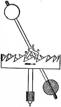
Fig. 1.—Verge Escapement.
These old clocks had what is called a verge escapement, and a balance. The train of wheels ended with a crown wheel, that is, a wheel serrated with teeth like those of a saw, placed parallel with its axis (fig. 1). These teeth, D, engaged with pallets CB, CA, mounted on a verge or staff placed parallel to the face of the crown wheel. As the crown wheel was turned round the teeth pushed the pallets alternately until one or the other slid past a tooth, and thus let the crown wheel rotate. When one pallet had slipped over a tooth, the other pallet caught a corresponding tooth on the opposite side of the wheel. The verge was terminated by a balance rod placed at right angles to it with a ball at each end. It is evident that when the force of any tooth on the crown wheel began to act on a pallet, it communicated motion to the balance and thus caused it to rotate. This motion would of course be accelerated, not uniformly, but according to some law dependent on the shape of the teeth and pallets. When the motion had reached its maximum, the tooth slipped past the pallet. The other pallet now engaged another tooth on the opposite side of the wheel. The motion of the balls, however, went on and they continued to swing round, but this time they were opposed by the pressure of the tooth. For a time they overcame that pressure, and drove the tooth back, causing a recoil. As, however, every motion if subjected to an adverse acceleration (i.e. a retardation) must come to rest, the balls stopped, and then the tooth, which had been forced to recoil, advanced in its turn, and the swing was repeated. The arrangement was thus very like a huge watch balance wheel in which the driving weight acted in a very irregular manner, not only as a driving force, but also as a regulating spring. The going of such clocks was influenced greatly by friction and by the oil on the parts, and never could be satisfactory, for the time varied with every variation in the swing of the balls, and this again with every variation of the effective driving force.
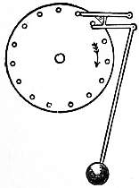
Fig. 2.—Galileo’s Escapement.
The first great step in the improvement of the balance clock was a very simple one. In the 17th century Galileo had discovered the isochronism of the pendulum, but he made no practical use of it, except by the invention of a little instrument for enabling doctors to count their patients’ pulse-beats. His son, however, is supposed to have applied the pendulum to clocks. There is at the Victoria and Albert Museum a copy of an early clock, said to be Galileo’s, in which the pins on a rotating wheel kick a pendulum outwards, remaining locked after having done so till the pendulum returns and unlocks the next pin, which then administers another kick to the pendulum (fig. 2). The interest of the specimen is that it contains the germ of the chronometer escapement and free pendulum, which is possibly destined to be the escapement of the future.
The essential component parts of a clock are:—
1. The pendulum or time-governing device;
2. The escapement, whereby the pendulum controls the speed of going;
3. The train of wheels, urged round by the weight or main-spring, together with the recording parts, i.e. the dial, hands and hour motion wheels;
4. The striking mechanism.
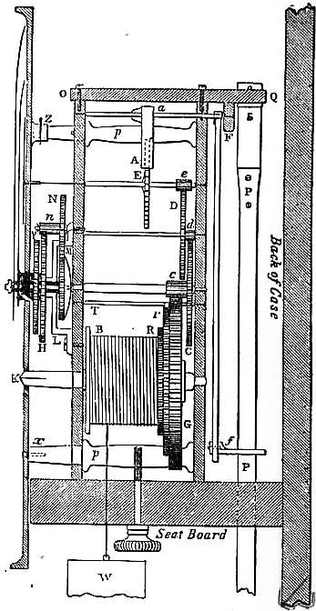
Fig. 3.—Section of House Clock.
The general construction of the going part of all clocks, except large or turret clocks, is substantially the same, and fig. 3 is a section of any ordinary house clock. B is the barrel with the cord coiled round it, generally 16 times for the 8 days; the barrel is fixed to its arbor K, which is prolonged into the winding square coming up to the face or dial of the clock; the dial is here shown as fixed either by small screws x, or by a socket and pin z, to the prolonged pillars p, p, which (4 or 5 in number) connect the plates or frame of the clock together, though the dial is commonly set on to the front plate by another set of pillars of its own. The great wheel G rides on the arbor, and is connected with the barrel by the ratchet R, the action of which is shown more fully in fig. 25. The intermediate wheel r in this drawing is for a purpose which will be described hereafter, and for the present it may be considered as omitted, and the click of the ratchet R as fixed to the great wheel. The great wheel drives the pinion c which is called the centre pinion, on the arbor of the centre wheel C, which goes through to the dial, and carries the long, or minute-hand; this wheel always turns in an hour, and the great wheel generally in 12 hours, by having 12 times as many teeth as the centre pinion. The centre wheel drives the “second wheel” D by its pinion d, and that again drives the scape-wheel E by its pinion e. If the pinions d and e have each 8 teeth or leaves (as the teeth of pinions are usually called), C will have 64 teeth and D 60, in a clock of which the scape-wheel turns in a minute, so that the seconds hand may be set on its arbor prolonged to the dial. A represents the pallets of the escapement, which will be described presently, and their arbor a goes through a large hole in the back plate near F, and its back pivot turns in a cock OFQ screwed on to the back plate. From the pallet arbor at F descends the crutch Ff, ending in the fork f, which embraces the pendulum P, so that as the pendulum vibrates, the crutch and the pallets necessarily vibrate with it. The pendulum is hung by a thin spring S from the cock Q, so that the bending point of the spring may be just opposite the end of the pallet arbor, and the edge of the spring as close to the end of that arbor as possible.
We may now go to the front (or left hand) of the clock, and describe the dial or “motion-work.” The minute hand fits on to a squared end of a brass socket, which is fixed to the wheel M, and fits close, but not tight, on the prolonged arbor of the centre wheel. Behind this wheel is a bent spring which is (or ought to be) set on the same arbor with a square hole (not a round one as it sometimes is) in the middle, so that it must turn with the arbor; the wheel is pressed up against this spring, and kept there, by a cap and a small pin through the end of the arbor. The consequence is, that there is friction enough between the spring and the wheel to carry the hand round, but not enough to resist a moderate push with the finger for the purpose of altering the time indicated. This wheel M, which is sometimes called the minute-wheel, but is better called the hour-wheel as it turns in an hour, drives another wheel N, of the same number of teeth, which has a pinion attached to it; and that pinion drives the twelve-hour wheel H, which is also attached to a large socket or pipe carrying the hour hand, and riding on the former socket, or rather (in order to relieve the centre arbor of that extra weight) on an intermediate socket fixed to the bridge L, which is screwed to the front plate over the hour-wheel M. The weight W, which drives the train and gives the impulse to the pendulum through the escapement, is generally hung by a catgut line passing through a pulley attached to the weight, the other end of the cord being tied to some convenient place in the clock frame or seat-board, to which it is fixed by screws through the lower pillars.
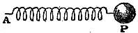
Fig. 4.
Pendulum.—Suppose that we have a body P (fig. 4) at rest, and that it is material, that is to say, has “mass.” And for simplicity let us consider it a ball of some heavy matter. Let it be free to move horizontally, but attached to a fixed point A by means of a spring. As it can only move horizontally and not fall, the earth’s gravity will be unable to impart any motion to it. Now it is a law first discovered by Robert Hooke (1635-1703) that if any elastic spring be pulled by a force, then, within its elastic limits, the amount by which it will be extended is proportional to the force. Hence then, if a body is pulled out against a spring, the restitutional force is proportional to the displacement. If the body be released it will tend to move back to its initial position with an acceleration proportioned to its mass and to its distance from rest. A body thus circumstanced moves with harmonic motion, vibrating like a stretched piano string, and the peculiarity of its motion is that it is isochronous. That is to say, the time of returning to its initial position is the same, whether it makes a large movement at a high velocity under a strong restitutional force, or a small movement at a lower velocity under a smaller restitutional force (see Mechanics). In consequence of this fact the balance wheel of a watch is isochronous or nearly so, notwithstanding variations in the amplitude of its vibrations. It is like a piano string which sounds the same note, although the sound dies away as the amplitude of its vibrations diminishes.
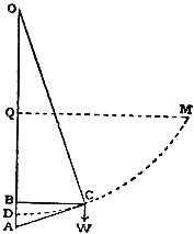
Fig. 5.
A pendulum is isochronous for similar reasons. If the bob be drawn aside from D to C (fig. 5), then the restitutional force tending to bring it back to rest is approximately the force which gravitation would exert along the tangent CA, i.e.
g cos ACW = g BC = g displacement BC .
OC length of pendulum
Since g is constant, and the length of the pendulum does not vary, it follows that when a pendulum is drawn aside through a small arc the force tending to bring it back to rest is proportional to the displacement (approximately). Thus the pendulum bob under the influence of gravity, if the arc of swing is small, acts as though instead of being acted on by gravity it was acted on by a spring tending to drag it towards D, and therefore is isochronous. The qualification “If the arc of swing is small” is introduced because, as was discovered by Christiaan Huygens, the arc of vibration of a truly isochronous pendulum should not be a circle with centre O, but a cycloid DM, generated by the rolling of a circle with diameter DQ = ½OD, upon a straight line QM. However, for a short distance near the bottom, the circle so nearly coincides with the cycloid that a pendulum swinging in the usual circular path is, for small arcs, isochronous for practical purposes.
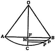
Fig. 6.
The formula representing the time of oscillation of a pendulum, in a circular arc, is thus found:—Let OB (fig. 6) be the pendulum, B be the position from which the bob is let go, and P be its position at some period during its swing. Put FC = h, and MC = x, and OB = l. Now when a body is allowed to move under the force of gravity in any path from a height h, the velocity it attains is the same as a body would attain falling freely vertically through the distance h. Whence if v be the velocity of the bob at P, v = √2gFM = √2g(h - x). Let Pp = ds, and the vertical distance of p below P = dx, then Pp = velocity at P × dt; that is, dt = ds/v. Also
ds = 1 = 1 ,
dx MP √x(2l - x)
whence
dt = ds = ldx . 1 = 1 √ l . dx . 1 .
v √x(2l - x) √2g(h - x) 2 g √x(p - x) √1 - (x/2l)
Expanding the second part we have
dt = 1 √ l . dx . ( 1 + x + ... ) .
2 g √x(h - x) 4l
If this is integrated between the limits of 0 and h, we have
t = π √ l . ( 1 + h + ... ) ,
g 8l
where t is the time of swing from B to A. The terms after the second may be neglected. The first term, π √l/g, is the time of swing in a cycloid. The second part represents the addition necessary if the swing is circular and not cycloidal, and therefore expresses the “circular error.” Now h = BC²/l = 2π²θ²l/360², where θ is half the angle of swing expressed in degrees; hence h/8l = θ²/52520, and the formula becomes
t = π √ l ( 1 + θ² ) .
g 52520
Hence the ratio of the time of swing of an ordinary pendulum of any length, with a semiarc of swing = θ degrees is to the time of swing of a corresponding cycloidal pendulum as 1 + θ²/52520 : 1. Also the difference of time of swing caused by a small increase θ′ in the semiarc of swing = 2θθ′ / 52520 second per second, or 3.3θθ′ seconds per day. Hence in the case of a seconds pendulum whose semiarc of swing is 2° an increase of .1° in this semiarc of 2° would cause the clock to lose 3.3 × 2 × 0.1 = .66 second a day.
Huygens proposed to apply his discovery to clocks, and since the evolute of a cycloid is an equal cycloid, he suggested the use of a flexible pendulum swinging between cycloidal cheeks. But this was only an example of theory pushed too far, because the friction on the cycloidal cheeks involves more error than they correct, and other disturbances of a higher degree of importance are left uncorrected. In fact the application of pendulums to clocks, though governed in the abstract by theory, has to be modified by experiment.
Neglecting the circular error, if L be the length of a pendulum and g the acceleration of gravity at the place where the pendulum is, then T, the time of a single vibration = π√(L/g). From this formula it follows that the times of vibration of pendulums are directly proportional to the square root of their lengths, and inversely proportional to the square root of the acceleration of gravity at the place where the pendulum is swinging. The value of g for London is 32.2 ft. per second per second, whence it results that the length of a pendulum for London to beat seconds of mean solar time = 39.14 in. nearly, the length of an astronomical pendulum to beat seconds of sidereal time being 38.87 in.
This length is calculated on the supposition that the arc of swing is cycloidal and that the whole mass of the pendulum is concentrated at a point whose distance, called the radius of oscillation, from the point of suspension of the pendulum is 39.14 in. From this it might be imagined that if a sphere, say of iron, were suspended from a light rod, so that its centre were 39.14 in. below its point of support, it would vibrate once per second. This, however, is not the case. For as the pendulum swings, the ball also tends to turn in space to and fro round a horizontal axis perpendicular to the direction of its motion. Hence the force stored up in the pendulum is expended, not only in making it swing, but also in causing the ball to oscillate to and fro through a small angle about a horizontal axis. We have therefore to consider not merely the vibrations of the rod, but the oscillations of the bob. The moment of the momentum of the system round the point of suspension, called its moment of inertia, is composed of the sum of the mass of each particle multiplied into the square of its distance from the axis of rotation. Hence the moment of inertia of the body I = Σ(ma²). If k be defined by the relation Σ(ma²) = Σ(m) X k², then k is called the radius of gyration. If k be the radius of gyration of a bob round a horizontal axis through its centre of gravity, h the distance of its centre of gravity below its point of suspension, and k’ the radius of gyration of the bob round the centre of suspension, then k′² = h² + k². If l be the length of a simple pendulum that oscillates in the same time, then lh = k′² = h² + k². Now k can be calculated if we know the form of the bob, and l is the length of the simple pendulum = 39.14 in.; hence h, the distance of the centre of gravity of the bob below the point of suspension, can be found.
In an ordinary pendulum, with a thin rod and a bob, this distance h is not very different from the theoretical length, l = 39.14 in., of a simple theoretical pendulum in which the rod has no weight and the bob is only a single heavy point. For the effect of the weight of the rod is to throw the centre of oscillation a little above the centre of gravity of the bob, while the effect of the size of the bob is to throw the centre of oscillation a little down. In ordinary practice it is usual to make the pendulum so that the centre of gravity is about 39 in. below the upper free end of the suspension spring and leave the exact length to be determined by trial.

Fig. 7.—Section of Westminster Clock Pendulum.
Since T = π√L/g, we have, by differentiating, dL/L = 2dT/T, that is, any small percentage of increase in L will correspond to double the percentage of increase in T. Therefore with a seconds pendulum, in order to make a second’s difference in a day, equivalent to 1/86,400 of the pendulum’s Regulation. rate of vibration, since there are 86,400 seconds in 24 hours, we must have a difference of length amounting to 2/86,400 = 1/43,200 of the length of the rod. This is 39.138/43,200 = .000906 in. Hence if under the pendulum bob be put a nut working a screw of 32 threads to the inch and having its head divided into 30 parts, a turn of this nut through one division will alter the length of the pendulum by .0009 in. and change the rate of the clock by about a second a day. To accelerate the clock the nut has always to be turned to the right, or as you would drive in a corkscrew and vice versa. But in astronomical and in large turret clocks, it is desirable to avoid stopping or in any way disturbing the pendulum; and for the finer adjustments other methods of regulation are adopted. The best is that of fixing a collar, as shown in fig. 7 at C, about midway down the rod, capable of having very small weights laid upon it, this being the place where the addition of any small weight produces the greatest effect, and where, it may be added, any moving of that weight up or down on the rod produces the least effect. If M is the weight of the pendulum and l its length (down to the centre of oscillation), and m a small weight added at the distance n below the centre of suspension or above the c.o. (since they are reciprocal), t the time of vibration, and -dt the acceleration due to adding m; then
-dt = m ( n - n² ) ;
t 2M l l²
from which it is evident that if n = l/2, then = dt/t = m/8M. But as there are 86400 seconds in a day, -dT, the daily acceleration, = 86400 dt, or 10800 m/M, or if m is the 10800th of the weight of the pendulum it will accelerate the clock a second a day, or 10 grains will do that on a pendulum of 15 ℔ weight (7000 gr. being = 1 ℔.), or an ounce on a pendulum of 6 cwt. In like manner if n = l/3 from either top or bottom, m must = M/7200 to accelerate the clock a second a day. The higher up the collar the less is the risk of disturbing the pendulum in putting on or taking off the regulating weights, but the bigger the weight required to produce the effect. The weights should be made in a series, and marked ¼, ½, 1, 2, according to the number of seconds a day by which they will accelerate; and the pendulum adjusted at first to lose a little, perhaps a second a day, when there are no weights on the collar, so that it may always have some weight on, which can be diminished or increased from time to time with certainty, as the rate may vary.
The length of pendulum rods is also affected by temperature and also, if they are made of wood, by damp. Hence, to ensure good time-keeping qualities in a clock, it is necessary (1) to make the rods of materials that are as little affected by such Compensation. influences as possible, and (2) to provide means of compensation by which the effective length of the rod is kept constant in spite of expansion or contraction in the material of which it is composed. Fairly good pendulums for ordinary use may be made out of very well dried wood, soaked in a thin solution of shellac in spirits of wine, or in melted paraffin wax; but wood shrinks in so uncertain a manner that such pendulums are not admissible for clocks of high exactitude. Steel is an excellent material for pendulum rods, for the metal is strong, is not stretched by the weight of the bob, and does not suffer great changes in molecular structure in the course of time. But a steel rod expands on the average lineally by .0000064 of its length for each degree F. by which its temperature rises; hence an expansion of .00009 in. on a pendulum rod of 39.14 in., that is .000023 of its length, will be caused by an increase of temperature of about 4° F., and that is sufficient to make the clock lose a second a day. Since the summer and winter temperatures of a room may differ by as much as 50° F., the going of a clock may thus be affected by an error of 12 seconds a day. With a pendulum rod of brass, which has a coefficient of expansion of .00001, a clock might gain one-third of a minute daily in winter as compared with its rate in summer. The coefficients of linear expansion per degree F. of some other materials used in making pendulums are as follows: white deal, .0000024; flint glass, .0000048; iron, .000007; lead, .000016; zinc, .000016; and mercury, .000033. The solid or cubical expansions of these bodies are three times the above quantities respectively.
The first method of compensating a pendulum was invented in 1722 by George Graham, who proposed to use a bob of mercury, taking advantage of the high coefficient of expansion of that metal. As now employed, the mercurial pendulum consists of a rod of steel terminating in a stirrup of the same metal on which rests a glass vessel full of mercury, having its centre of gravity about 39 in. below the point of suspension of the pendulum. For each Fahrenheit degree of temperature the centre of gravity of the bob is lowered by the expansion of the rod about 1⁄4000 of an inch. The glass vessel and the mercury in it have therefore to be so contrived, that their centre of gravity will rise 1⁄4000 in. per degree F. The glass having a small coefficient of expansion, the lateral expansion of the mercury will be checked by it, and this will help to raise the column. For the linear coefficient of expansion of glass is .0000048 per degree F., whence the sectional area of a glass vessel increases by .0000096 per degree F., and therefore the coefficient of vertical expansion of a column of mercury whose volumetric expansion coefficient is .0001 per degree F. is (.0001 - .0000096) = .0000904. Let x be the height of the vessel necessary to compensate a steel rod upon the bottom of which it rests. Then, the coefficient of expansion of steel being .0000066 per degree F., we have
x (.0000904 - .0000066) = .0000066 × 39.14, whence x = 6¼ in.
2
It must, however, be remembered that the glass jar has some weight and that it does not rise by anything like the amount of the mercury. This tends to keep the centre of gravity down. So that the height of mercury of 6¼ in. will not be sufficient to effect the compensation, and about 6¾ to 7 in. will be required. Some authors specify 7 in.; this is when the diameter of the jar is small. A certain amount of negative compensation must also be deducted to allow for the changes of temperature in the air, as will presently be seen; this amounts in the case of mercury to about 1⁄5 in.
In consequence of the complication of all these calculations it is usual to allow about 6¾ to 7 in. of mercury in the glass vessel and to adjust the exact amount of mercury by trial.
Another very good form of mercurial pendulum was proposed by E. J. Dent; it consists of a cast-iron jar into the top of which the steel pendulum rod is screwed, having its end plunged into the mercury contained in the jar. By this means the mercury, jar and rod rapidly acquire the same temperature. This pendulum is less likely to break than the form just described. The depth of mercury required in an iron jar is stated by Lord Grimthorpe to be 8½ to 9 in. The reason why it is greater than it is when a glass jar is employed is that iron has a larger coefficient of expansion than glass, and that it is also heavier. In all cases, however, of mercury pendulums experiment seems to be the only ultimate test of the quantity of mercury required, for the results are so complicated by the behaviour of the oil and the barometric errors that at its best the regulation of a clock can only be ultimately a matter of scientifically guided compromise. A small amount of compensation of a purely experimental character is also allowed to compensate the changes which temperature effects on the suspension spring. This is sometimes made as much as 1⁄6 of the length correction.
As an alternative to the mercurial pendulum other systems have been employed. The “gridiron” pendulum consists of a group of alternate rods of steel and brass, so arranged that the expansion of the brass acts upwards and counteracts that of the steel downwards. It was invented in 1726 by John Harrison. Assuming that 9 rods are used—5 of steel and 4 of brass—their lengths may be as follows from pin to pin:—Centre steel rod 31.5 in.; 2 steel rods next the centre 24.5 in.; 2 steel rods farthest from centre 29.5 in.; from the lower end of outside steel rods to centre of bob 3 in.; total 89.5 in. Of the 4 brass rods the 2 outside ones are 26.87 in.; and the two inside ones 22.25 in.; total 49.12 in. Thus the expansion of 88½ in. of steel is counteracted by the expansion of 491⁄8 in. of brass. Everything depends, however, on the expansion coefficient of the steel and brass employed, the requirement in every case being that of total lengths of the brass and iron should be in proportion to the linear coefficients of expansion of those metals. The above figures are for a very soft brass and steel. Thos. Reid, with more ordinary steel and brass, prescribed a ratio of 112 to 71, Lord Grimthorpe a ratio of 100 to 61. It is absolutely necessary to put the actual rods to be used for making the pendulum in a hot water bath, and measure their expansions with a microscope.
John Smeaton, taking advantage of a far greater expansion coefficient of zinc as compared with brass, proposed to use a steel rod with a collar at the bottom, on which rested a hard drawn zinc rod. From this rod hung a steel tube to which the bob was attached. The total length of the steel rod and of the steel tube down to the centre of the bob was made to the total length of the zinc tube, in the ratio of 5 to 2 (being the ratio of the expansions of zinc and steel); for a 39.14 in. pendulum we should therefore want a zinc tube equal in length to 2⁄3 (39.14) = 26¼ in. In practice the zinc tube is made about 27 in. long, and then gradually cut down by trial. In fact the weight of a heavy pendulum squeezes the zinc, and it is impossible by mere theory to determine what will be its behaviour. The zinc tube must be of rolled zinc, hard drawn through a die, and must not be cast. Ventilating holes must be made in suitable places in the steel tube and the collar on which it rests, to ensure that changes of temperature are rapidly communicated throughout the system.
A pendulum with a rod of dry varnished deal is tolerably compensated by a bob of lead or of zinc 10½ to 13 in. in height, resting on a nut at the bottom of the rod.
The old methods of pendulum compensation for heat may now be considered as superseded by the invention of “invar,” a combination of nickel and steel, due to Charles E. Guillaume, of the International Office of Weights and Measures at Invar. Sèvres near Paris. This alloy has a linear coefficient of expansion on the average of .000001 per degree centigrade, that is to say, only about 1⁄11 that of ordinary steel. Hence it can be easily compensated by means of brass, lead or any other suitable metal. Brass is usually employed. In the invar pendulum introduced into Great Britain by Mr Agar Baugh a departure is made from the previous practice of merely calculating the length of the compensator, fastening it to the lower part of the pendulum, and attaching it to the centre of the bob. In the case of these pendulums, accurate computations are made of the moments of inertia of every separate individual part. Thus, for instance, since an addition of volume due to the effect of heat to the upper part of the bob has a different effect upon the moment of inertia from that of an equal quantity added to the lower part of the bob, the bob is suspended not from its centre, but from a point about 1⁄10 in. below it, the distance varying according to the shape of the bob, so that the heat expansion of the bob may cause its centre of gravity to rise and compensate the effect of its increased moment of inertia. Again the suspension spring is measured for isochronism, and an alloy of steel prepared for it which does not alter its elasticity with change of temperature. Moreover, since rods of invar steel subjected to strain do not acquire their final coefficients of expansion and elasticity for some time, the invar is artificially “aged” by exposure to strain and heat.
These considerations serve as a guide in arranging for the compensation of the expansion of the rod and bob due to change of temperature. But they are not the only ones required; we have also to deal with changes due to the density of the air in which the pendulum is moving. A body suspended in a fluid loses in weight by an amount equal to the weight of the fluid displaced, whence it follows that a pendulum suspended in air has not the weight which ought truly to correspond to its mass. M remains constant while Mg is less than in a vacuum. If the density of the air remained constant, this loss of weight, being constant, could be allowed for and would make no difference to the time-keeping. The period of swing would only be a little increased over what it would be in vacuo. But the weight of a given volume of air varies both with the barometric pressure and also with temperature. If the bob be of type metal it weighs less in air than in a vacuum by about .000103 part, and for each 1° F. rise in temperature (the barometer remaining constant and therefore the pressure remaining the same), the variation of density causes the bob to gain .00000024 of its weight. This, of course, makes the pendulum go quicker. Since the time of vibration varies as the inverse square root of g, it follows that a small increment of weight, the mass remaining constant, produces a diminution of one half that increment in time of swing. Hence, then, a rise of temperature of 1° F. will produce a diminution in the time of swing of .00000012th part or .0104 second in a day. But in making this calculation it has been assumed that the mass moved remains unaltered by the temperature. This is not so. A pendulum when swinging sets in motion a volume of air dependent on the size of the bob, but in a 10 ℔ bob nearly equal to its own volume. Hence while the rise of 1° of temperature increases the weight by .00000012th part, it also decreases the mass by about the same proportion, and therefore the increase of period due to a rise of temperature of 1° F. will, instead of being .0104 second a day, be about .02 second. This must be compensated negatively by lengthening the pendulum by about .02⁄1000 in. for each degree of rise of temperature, which will require a piece of brass about 2 in. long. It follows, therefore, that with an invar rod having a linear expansion coefficient of .0000002 per degree F., which requires a piece of brass about .8 in. long to compensate it, the compensation which is to regulate both the expansion of the rod and also that of the air must be .8 in. - 2 in., or -1.2 in.; so that the bob must be hung downwards from a piece of brass nearly 11⁄5 in. in length. If the coefficient of expansion of the invar were .00000053 per degree F., then the two corrections, one for the expansion of the rod and the other for the expansion of the air, would just neutralize one another, and the pendulum rod would require no compensator at all. There are a number of other refinements which might be added, but which are too long for insertion here. By taking in all the sources of error of higher orders, it has been possible to calculate a pendulum so accurately that, when the clock is loaded with the weight sufficient to give the pendulum the arc of swing for which it is designed, a rate of error has been produced of only half a minute in a year. These refinements, however, are only required for clocks of precision; for ordinary clocks an invar pendulum with a lead bob and brass compensator is quite sufficient.
Invar pendulum rods are often made of steel with coefficients of expansion of about .0000012 linear per 1° C.; such a bob as this would require about 6.7 cm. of brass to compensate it, and, deducting 5 cm. of brass for the air compensation, this leaves about 1.7 cm. of positive compensation for the pendulum. But as has been said, the exact deduction depends on the shape and size of the bob, and the metal of which it is made. The diameters of the rods are 8 mm. for a 15 ℔ bob, 5 mm. for a 4 ℔ bob, and 12 to 15 mm. for a 60 ℔ bob. The bob is either a single cylinder or two cylinders with the rod between them. Lenticular and spherical bobs are not used. The great object is to allow the air ready access to all parts of the rod and compensator, so that they are all heated or cooled simultaneously. The bobs are usually made of a compound of lead, antimony, and tin, which forms a hard metal, free from bubbles and with a specific gravity of about 10. The usual weight of the bobs of the best pendulums for an ordinary astronomical clock is about 15 ℔. A greater weight than this is found liable to make the support of the pendulum rock and to put an undue strain on the parts, without any corresponding advantage. The rods used are all artificially aged, and have their heat expansion measured. No adjusting screw at the bottom is provided, the regulation being done by the addition of weights half way up the rod. An adjusting screw at the bottom has the disadvantage that it is impossible to know on which of the threads the rod is really resting; hence extra compensation may be introduced when not required. It is considered better that the supports of the bob should be rigid and invariable.
The effect of changes in the pressure of the air as shown by a barometer is too important to be omitted in the design of a good clock. But we do not propose to give more than a mere indication of the principles which govern compensation Barometrical error. for this effect, since the full discussion of the problem would be too protracted. We have seen that the action of the air in affecting the time of oscillation of a pendulum depends chiefly on the fact that its buoyancy makes the pendulum lighter, so that while the mass of the bob which has to be moved remains the same or nearly the same, the acceleration of gravity on it has less effect. A volume of air at ordinary temperature and pressure has, as has been said, .000103 the weight of an equal volume of type metal, whence it follows that the acceleration of gravity on a type metal bob in air is .999897 of the acceleration of gravity on the bob in vacuo. If, therefore, we diminish the value of g in the formula T = π√L/g by .000103, we shall have the difference of time of vibration of a type metal bob in air, as compared with its time in vacuo, and this, by virtue of the principle used when discussing the increase of time of oscillation due to increased pendulum lengths, is ½(.000103) second in one second, or about 4½ seconds in a day of 86,400 seconds. It follows that a barometric pressure of 30 in. causes a loss of 4½ seconds in the day, equivalent to .15 second per day for each inch of difference of the barometer. But, as has already been explained, the effect of the mass of the air transported with the pendulum must also be taken into account and therefore the above figures must be doubled or nearly doubled. A difference of 30 in. of barometric pressure would thus make a difference of 9 seconds per day in the rate of the pendulum, and the clock would lose about 1⁄3 of a second a day for each inch of rise of the barometer, the result being of the same magnitude as would be produced by a fall of temperature of 15° F. in the air. Either of these effects would require a shortening of the pendulum of 1⁄3000 in. This estimate is not far from the truth, for observations taken at various European observatories on various clocks, and collected by Jakob Hilfiker, give a mean of .15 second of retardation per day per centimetre of barometric pressure, or .37 second per day for each inch rise of the barometer.
In order to counteract variations in going which must thus obviously be produced by variations of barometrical pressure, attempts have been made purposely to disturb the isochronism of the pendulum, by making the arcs of vibration abnormally large. Again, the bob has been fitted with a piece of iron, which is subjected to the attraction of a piece of magnetized steel floating on the mercury in the open end of a barometer tube, so that when the barometer falls the attraction is increased and the pendulum retarded. Again, mercury barometers have been attached to pendulums. A simple method is to fix an aneroid barometer with about seven compartments on the pendulum about 5 to 6 in. below the suspension spring, and to attach to the top of it a suitable weight which is lowered as the barometric pressure increases. One of the best methods of neutralizing the effects of variations of barometric pressure is to enclose the whole clock in an air-tight case, which may either be a large glass cylinder or a square case with a stout plate-glass front. This renders it independent of outside variations, whether of temperature or pressure, and keeps the density of the air inside the case uniform. If the case could be completely, or almost completely, exhausted of air, and kept so exhausted, of course the pendulum would experience the minimum of resistance and would have to be lengthened a little. But in practice it is impossible to secure the maintenance of a good vacuum without sealing up the case in such a way as to render repairs very difficult, and this plan is therefore rarely resorted to. What is usually done is to put the clock in a metal case covered with a thick sheet of plate glass bedded in india-rubber strips, and held down by an iron flanged lid or frame firmly fixed by means of small bolts. An air-pump is attached to the case, a turn-off tap being inserted, and by a few strokes the pressure of the air inside the case can be lowered to (say) 29 in., or a little below the usual barometric height at the place where the clock is. The difference of pressure being small, the tendency of air from outside to leak in is also small, and if the workmanship is good the inside pressure will remain unaltered for many days. In any case the difference produced by leakage will be small, and will not greatly affect the going of the clock. With care, and a daily or weekly touch of the pump, the pressure inside can be kept practically constant, and hence the atmospheric error will be eliminated. The cover has also incidentally the effect of keeping damp and fumes from the clock and thus preserving it from rust, especially if a vessel with quicklime or some hygroscopic material be put in the case.
Cases have considerable effect on the air, which moves with a pendulum and is flung off from it at each vibration; the going rate of a chronometer can be altered by removing the case. It is therefore desirable that cases enclosing pendulums should be roomy. Many people prefer to omit the air-tight case, and to keep a record of barometric, thermometric and hygrometric changes, applying corrections based on these to the times shown by the clock.
It was formerly usual to suspend pendulums by means of a single spring about ½ in. wide riveted with chops of metal. The upper chop had a pin driven through it, which rested in grooves so as to allow the pendulum to hang vertically. The Suspension of pendulums. best modern pendulums are now made with two parallel springs put a little less than an inch apart. The edges of the chops where the springs enter are slightly rounded so as to avoid too sharp bending of the springs. Suspension of pendulums on knife edges was tried by B. L. Vulliamy and others, but did not prove a success.
It was once thought that lenticular pendulum bobs resisted the air less than those of other shapes, but it was forgotten that their large surface offered more “skin friction.” They are now no longer used, nor are spheres on account of difficulty of construction. A cylinder is the best form of bob; it is sometimes rounded at the top and bottom.
Escapements.—The term escapement is applied to any arrangement by which, as the wheels rotate, periodic impulses are given to the pendulum, while at the same time the motion of the wheels is arrested until the vibration of the pendulum has been completed. It thus serves as a mechanism for both counting and impelling. Since the vibrations of a pendulum through small arcs are performed in times independent of the length of the arc, it follows that if a pendulum hanging at rest receive an impulse it will swing out and in again, and the time of its excursion outwards and of its return will remain the same whatever (within limits) be the arc of the swing, and whatever be the impulse given to it. If the impulse is big, it starts with a high velocity, but makes a larger excursion outwards, and the distance it has to travel counteracts its increase of speed, so that its time remains the same. Hence a pendulum, if free to swing outwards and in again, without impediment, will adapt the length of its swing to the impulse it has received, and any interference with it, as by the locking or unlocking of the escapement, will be far less deleterious to its isochronism when such interference occurs at the middle of its path rather than at the ends. It follows that the best escapement will be one which gives an impulse to the pendulum for a short period at the lowest point of its path, and then leaves it quite free to move as it chooses until the time comes for the next impulse.
But a pendulum is not quite truly isochronous, and has its time slightly affected by an increase of its arc; it is therefore desirable that the impulses given to it shall always be equal. If the escapement forms the termination of a clock-train impelled by a weight, the driving force of the escapement is apt to vary according to the friction of the wheels, while every change in temperature causes a difference in the thickness of the oil. It is therefore desirable, if possible, to secure uniformity of impulse—say, by causing the train of wheels to lift up a certain specified weight, and let it drop on the pendulum at regular intervals, or by some equivalent method.
The two requirements above stated have given rise respectively to what are known as detached escapements, and remontoires, which will be described presently. In the first place, however, it is desirable to describe the principal forms of escapement in ordinary use.
The balance escapement, which has been already mentioned, was in use before the days of pendulums. It was to a Balance escapement. balance escapement that Huygens applied the pendulum, by removing the weight from one arm and increasing the length of the other arm.
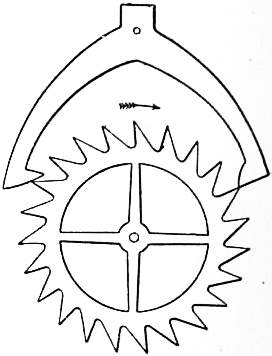
Fig. 8.—Anchor or Recoil Escapement.
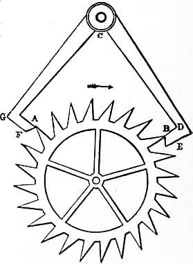
Fig. 9.—Dead Escapement.
Very shortly afterwards R. Hooke invented the anchor or recoil escapement. This is represented in fig. 8, where a tooth of the escape-wheel is just escaping from the right pallet, and another tooth at the same time falls upon the left-hand pallet at Anchor escapement. some distance from its point. As the pendulum moves on in the same direction, the tooth slides farther up the pallet, thus producing a recoil, as in the crown-wheel escapement. The acting faces of the pallets should be convex. For when they are flat, and of course still more when they are concave, the points of the teeth always wear a hole in the pallets at the extremity of their usual swing, and the motion is obviously easier and therefore better when the pallets are made convex; in fact, they then approach more nearly to the “dead” escapement, which will be described presently. The effect of some escapements is not only to counteract the circular error, or the natural increase of the time of a pendulum as the arc increases, but to over-balance it by an error of the contrary kind. The recoil escapement does so; for it is almost invariably found that whatever may be the shape of these pallets, the clock loses as the arc of the pendulum falls off, and vice versa. It is unfortunately impossible so to arrange the pallets that the circular error may be thus exactly neutralized, because the escapement error depends, in a manner reducible to no law, upon variations in friction of the pallets themselves and of the clock train, which produce different effects; and the result is that it is impossible to obtain very accurate time-keeping from any clock of this construction. The point in which the anchor escapement was superior to all that had gone before, was that it would work well with a small arc of swing of the pendulum. The balance escapement, even when adapted to a pendulum, necessitated a swing of some 20°, and hence the circular error, that is to say, the deviation of the path from a true cycloid, was considerable. But with an anchor escapement the pendulum swing need be only 3° or 4°. On the other hand, it violates the conditions above laid down for a perfect escapement, inasmuch as the pendulum is never free, but at the end of its swing is still operated on by the escapement, which it causes to recoil.
To get rid of this defect the dead escapement, or, as the French call it, l’échappement à repos, was invented by G. Graham. It is represented in fig. 9. It will be observed that the teeth of the scape-wheel have their points set the opposite way Dead escapements. to those of the recoil escapement. The tooth B is here represented in the act of dropping on to the right-hand pallet as the tooth A escapes from the left pallet. But instead of the pallet having a continuous face as in the recoil escapement, it is divided into two, of which BE on the right pallet, and FA on the left, are called the impulse faces, and BD, FG, the dead faces. The dead faces are portions of circles (not necessarily of the same circle), having the axis of the pallets C for their centre; and the consequence evidently is, that as the pendulum goes on, carrying the pallet still nearer to the wheel than the position in which a tooth falls on to the corner A or B of the impulse and the dead faces, the tooth still rests on the dead faces without any recoil, until the pendulum returns and lets the tooth slide down the impulse face, giving the impulse to the pendulum as it goes. In order to diminish the friction and the necessity for using oil as far as possible, the best clocks are made with jewels (sapphires are the best for the purpose) let into the pallets.
The pallets are generally made to embrace about one-third of the circumference of the wheel, and it is not at all desirable that they should embrace more; for the longer they are, the longer is the run of the teeth upon them, and the greater the friction. In some clocks the seconds hand moves very slowly and rests a very short time; this shows that the impulse is long in proportion to the arc of swing. In others the contrary is the case. A not uncommon proportion is that out of a total arc of swing of 3°, 2°, or about one degree on each side of the vertical, are occupied in receiving the impulse. In other words, the points F and A should subtend an angle of 2° at the centre C. It is not to be forgotten that the scape-wheel tooth does not overtake the face of the pallet immediately, on account of the moment of inertia of the wheel. The wheels of astronomical clocks, and indeed of all English house clocks, are generally made too heavy, especially the scape-wheel, which, by increasing the moment of inertia, causes a part of the work to be lost in giving blows, instead of being all used up in gentle pushes.
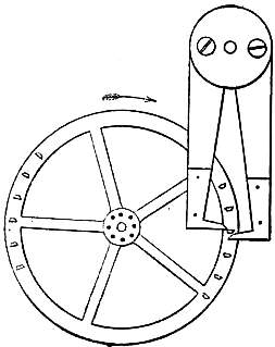
Fig. 10.—Pin-Wheel Escapement.
A very useful form of the dead escapement, which is adopted in many of the best turret clocks, is called the “pin-wheel escapement.” Fig. 10 will sufficiently explain its action and construction. Its advantages are—that it does not require so much accuracy as the other; if a pin gets broken it is easily replaced, whereas in the other the wheel is ruined if the point of a tooth is injured; a wheel of given size will work with more pins than teeth, and therefore a train of less velocity will do, and that sometimes amounts to a saving of one wheel in the train, and a good deal of friction; and the blow on both pallets being downwards, instead of one up and the other down, the action is more steady; all which things are of more consequence in the heavy and rough work of a turret clock than in an astronomical one. It has been found expedient to make the dead faces not quite dead, but with a very slight recoil, which rather tends to check the variations of arc, and also the general disposition to lose time if the arc is increased; when so made the escapement is generally called “half-dead.”
In the dead escapement, during each excursion of the pendulum the repose surface of the pallets rubs against the points of the teeth of the scape-wheel. Thus the pendulum is subject to a constant retardation by friction. Curiously enough, this friction, which at first sight might appear a defect, is an advantage, and to a large extent accounts for the excellence of the escapement. For if the driving force of the clock is increased so that the impulse on the pallets is greater, the velocity of the pendulum is increased. But this very increase of the driving force causes a greater pressure of the teeth of the scape-wheel on the rest-faces of the pallets, and hence counteracts the increased drive of the pendulum by an increased frictional retardation. If the clock weight be enormously increased, the frictional retardation becomes increased relatively in a greater proportion than the drive, so that as the weight of the clock is increased the pendulum’s time of vibration is first diminished, until at last a neutral point is reached and finally the increased loading of the clock weight begins to make the time of vibration increase again. It is the neutral point which it is desirable to arrange for, and only trial and experience can so fit the shape and size of the pallets, scape-wheel and clock weight to one another, as to secure that a moderate variation of the driving power neither accelerates nor retards the motion of the pendulum, while at the same time such an arc of vibration is secured as shall be least subject to barometric error, and not have too great a circular error. The celebrated clockmaker B. L. Vulliamy (1780-1854) greatly improved Graham’s escapement by careful experiment, and other makers introduced further improvements into the shape of the scape-wheel and pallets, so that the best form of the deadbeat escapement is now fairly well determined and is given in books upon horology. For small clocks a little slope is given to the rest-faces so as to diminish the friction retardation. This is known as the half-dead escapement. The pin-wheel escapement, if properly constructed, is also “dead,” that is to say, the outward swing of the pendulum is unfettered except by the slight friction of the teeth against the dead faces of the pallets.
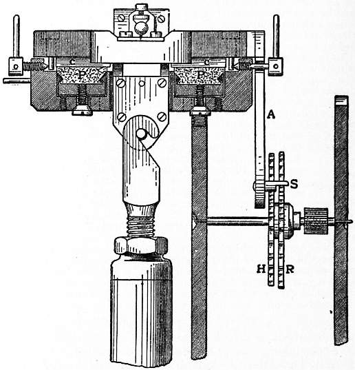
Fig. 11.—Riefler’s Escapement.
In order to diminish the effect of the impact of the scape-wheel on the pallets, and of the crutch on the pendulum rod, the plan has been tried of making the crutch into an elastic spring. In theory this of course would not destroy the isochronism of the pendulum, for it would only be to apply upon the pendulum a force at right angles to the rod, and varying as the displacement. Hence any acceleration given by such a spring would, like the action of gravity, be harmonic, and it is an analytical principle that harmonic motions superposed on one another still remain harmonic. Hence, then, the action of a spring superadded upon the action of gravity on a pendulum still leaves the motion harmonic. But changes of temperature would affect the spring considerably. In the case of such a spring the repose faces of Graham’s escapement might be minimized and the escapement checked each side by a stop, so as to prevent the pallets from rubbing on the points of the scape-wheel. Graham’s escapement can, if well made, be arranged so as not to vary more than an average of 1⁄30 of a second from its mean daily rate, and this is so good a result that many people doubt whether further effort in the direction of inventing new escapements will result in any better form. Two adaptations of Graham’s escapement have been made, one by Clemens Riefler of Nesselwang, and the other by L. Strasser of Glashütte, Saxony, which give good results in practice. Riefler’s scheme is to mount the upper block, into which the suspension spring is fastened, upon knife edges, and rock it to and fro by the action of a modified Graham’s escapement, thus giving impulses to the pendulum. Fig. 11 shows the arrangement. PP are the agates upon which the knife edges CC rest. A is the anchor, RH the scape-wheels, and S the pallets.
Strasser’s clock is arranged on the same idea as that of Riefler, only that the rocking motion is given, not to the springs that carry the pendulum, but to a second pair of springs placed outside of them and parallel to them. The weight of the pendulum is therefore carried by an upper stationary block, but above that a second block is subjected to the rocking motion of the anchor. The general design is shown in fig. 12. The pallets are each formed of two stones, so contrived as to minimize the banging of the teeth of the scape-wheel. Both Riefler’s and Strasser’s clocks aim at haying a virtually free pendulum; in fact, they are in reality adaptations of the principle of the spring-clutch to Graham’s escapement. The weak point in both is the tampering with the suspension.
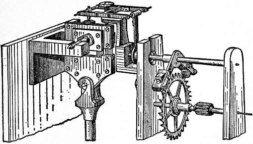
Fig. 12.—Strasser’s Escapement (Strasser & Rohde).
The dead escapement is not, however, truly free. In order to make a free escapement it would be necessary to provide that as soon as the pendulum approached its centre position, some pin or projecting point upon it should free the Detached escapement. escapement wheel, a tooth of which should thus be enabled to leap upon the back of the pendulum, give it a short push, and then be locked until the pendulum had returned and again swung forward. An arrangement of this kind is shown in fig. 13. Let A be a block of metal fixed on the lower end of a pendulum rod. On the block let a small pall B be fastened, free to move round a centre C and resting against a stop D. Let E be a 4-leaved scape-wheel, the teeth of which as they come round rest against the bent pall GFL at G. The pall is prevented from flying too far back by a pin H, and kept up to position by a very delicate spring K. As soon as the pendulum rod, moving from left to right, has arrived at the position shown in the figure, the pall B will engage the arm FL, force it forwards, and by raising G will liberate the scape-wheel, a tooth of which, M, will thus close upon the heel N of the block A, and urge it forward. As soon, however, as N has arrived at G the tooth M will slip off the block A and rest on the pall G, and the impulse will cease. The pendulum is now perfectly free or “detached,” and can swing on unimpeded as far as it chooses. On its return from right to left, the pall B slips over the pall L without disturbing it, and the pendulum is still free to make an excursion towards the left. On its return journey from left to right the process is again repeated. Such an escapement operates once every 2 seconds. One made on a somewhat similar plan was applied to a clock by Robert-Houdin, about 1830, and afterwards by Mr Haswell, and another by Sir George Airy. But the principle was already an old one, as may be seen from fig. 14, which was the work of an anonymous maker in the 18th century. A consideration of this escapement will show that it is only the application of the detached chronometer escapement to a clock.
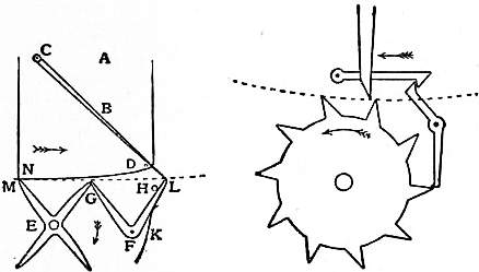
Fig. 13.—Free Escapement. Fig. 14.—Free Escapement (old form).
Even detached escapements, however, are not perfect. In order that an escapement should be perfect, the impulse given to the pendulum should be always exactly the same. It may be asked why, if the time of oscillation of the pendulum be independent of the amplitude of the arc of vibration, and hence of the impulse, it is necessary that the impulse should be uniform. The answer is that the arc of vibration not being a true cycloid, as it should be if true isochronism is to be secured, but being the arc of a circle, any change of amplitude of vibration produces a change of time in the swing given by the formula 3⁄2(a² - b²) = loss in seconds per day, where a and b are the semi-arcs of vibration estimated in degrees. Thus 10’ increase of arc in a swing of 4°, that is to say, .1 in. increase of arc in a total arc of 2½ in., produces an error of about a second a day. Now cold weather, by making the oil thick and thus clogging the wheels, will easily produce such a change of arc; dust will also make a change even though the clock weight, acted on by gravity, still exerts a uniform pull. Besides, if the clock has work to do of a varying amount—as when the hands of a turret clock are acted on by a heavy wind pressure tending sometimes to retard them, sometimes to drive them on—then it is clear that the impulses given by the scape-wheel to the pendulum may be very unequal, and that the arc of vibration of the pendulum may thus be seriously affected and its isochronism disturbed.
To abolish errors arising from the changes in the force driving the escapement, what is known as the “remontoire” system was adopted. It first came into use for watches, which was perhaps natural, seeing that the driving force of a watch Remontoire. is not a uniform weight like that of a clock, but depends on springs, which are far less trustworthy. The idea of a remontoire is to disconnect the escapement from the clock train, and to give the escapement a driving power of its own, acting as directly as possible on the pallets without the intervention of a clock-train containing many wheels. The escapement is thus as it were made into a separate clock, which of course needs repeated winding, and this winding is effected by the clock-train. From this it results that variations in the force transmitted by the clock-train merely affect the speed at which the “rewinding” of the escapement is effected, but do not affect the force exerted by the driving power of the escapement.
There are several modes of carrying out this plan. The first of them is simply to provide the scape-wheel with a weight or spring of its own, which spring is wound up by the clock-train as often as it runs down. Contrivances of this kind are Train remontoires. called train remontoires. In arranging such a remontoire it is obvious that the clock-train must be provided with a stop to prevent it from overwinding the scape-wheel weight or spring, and further, that there must be on the scape-wheel some sort of stud or other contrivance to release the clock-train as soon as the scape-wheel weight or spring has run down and needs rewinding. We believe the first maker of a large clock with a train remontoire was Thomas Reid of Edinburgh, who described his apparatus in his book on Horology (1819). The scape-wheel was driven by a small weight hung by a Huygens’s endless chain, of which one of the pulleys was fixed to the arbor, and the other rode upon the arbor, with the pinion attached to it, and the pinion was driven and the weight wound up by the wheel below (which we will call the third wheel), as follows. Assuming the scape-wheel to turn in a minute, its arbor has a notch cut half through it on opposite sides in two places near to each other; on the arbor of the wheel, which turns in ten minutes, suppose, there is another wheel with 20 spikes sticking out of its rim, but alternately in two different planes, so that one set of spikes can only pass through one of the notches in the scape-wheel arbor, and the other set only through the other. Whenever, then, the scape-wheel completes a half-turn, one spike is let go, and the third wheel is able to move, and with it the whole clock-train and the hands, until the next spike of the other set is stopped by the scape-wheel arbor; at the same time the pinion on that arbor is turned half round, winding up the remontoire weight, but without taking its pressure off the scape-wheel. Reid says that, so long as this apparatus was kept in good order, the clock went better than it did after it was removed in consequence of its getting out of order from the constant banging of the spikes against the arbor.
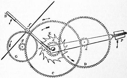
Fig. 15.—Gravity Train Remontoire.
A clock at the Royal Exchange, London, was made in 1844 on the same principle, except that, instead of the endless chain, an internal wheel was used, with the spikes set on it externally, which is one of the modes by which an occasional secondary motion may be given to a wheel without disturbing its primary and regular motion. The following is a more simple arrangement of a gravity train remontoire, much more frequently used in principle. Let E in fig. 15 be the scape-wheel turning in a minute, and e its pinion, which is driven by the wheel D having a pinion d driven by the wheel C, which we may suppose to turn in an hour. The arbors of the scape-wheel and hour-wheel are distinct, their pivots meeting in a bush fixed somewhere between the wheels. The pivots of the wheel D are set in the frame AP, which rides on the arbors of the hour-wheel and scape-wheel, or on another short arbor between them. The hour-wheel also drives another wheel G, which again drives the pinion f on the arbor which carries the two arms fA, fB; and on the same arbor is set a fly with a ratchet, like a common striking fly, and the numbers of the teeth are so arranged that the fly will turn once for each turn of the scape-wheel. The ends of the remontoire arms fA, fB are capable of alternately passing the notches cut half through the arbor of the scape-wheel, as those notches successively come into the proper position at the end of every half-minute; as soon as that happens the hour-wheel raises the movable wheel D and its frame through a small angle; but, nevertheless, that wheel keeps pressing on the scape-wheel as if it were not moving, the point of contact of the wheel C and the pinion d being the fulcrum or centre of motion of the lever AdP. It will be observed that the remontoire arms fA, fB have springs set on them to diminish the blow on the scape-wheel arbor, as it is desirable not to have the fly so large as to make the motion of the train, and consequently of the hands, too slow, to be distinct.
Another kind of remontoire is on the principle of one bevelled wheel lying between two others at right angles to it. The first of the bevelled wheels is driven by the train, and the third is fixed to the arbor of the scape-wheel; and the intermediate bevelled wheel, of any size, rides on its arbor at right angles to the other two arbors which are in the same line. The scape-wheel will evidently turn with the same average velocity as the first bevelled wheel, though the intermediate one may move up and down at intervals. The transverse arbor which carries it is let off and lifted a little at half-minute intervals, as in the remontoire just now described; and it gradually works down as the scape-wheel turns under its pressure, until it is freed again and lifted by the clock-train.
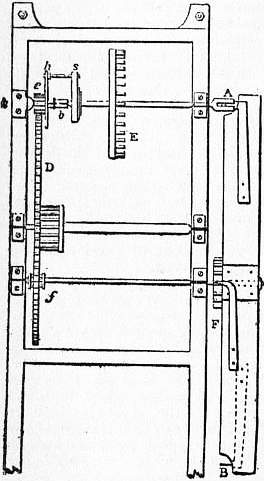
Fig. 16.—Spring Remontoire.
In all these gravity remontoires, however, only the friction of the heavy parts of the train and the dial-work is got rid of, and the scape-wheel is still subject to the friction of the remontoire wheels, which, though much less than the other, is still something considerable. Accordingly, attempts have frequently been made to drive the scape-wheel by a spiral spring, like the mainspring of a watch. One of these was described in the 7th edition of this encyclopaedia; and Sir G. Airy invented another on the same principle, of which one specimen is still going well. One of the best forms of such a remontoire is shown in fig. 16, in which A, B, D, E, e, f are the same things as in fig. 15. But e, the scape-wheel pinion, is no longer fixed to the arbor, nor does it ride on the arbor, as had been the case in all the previous spring remontoires, thereby producing probably more friction than was saved in other respects; but it rides on a stud k, which is set in the clock frame. On the face of the pinion is a plate, of which the only use is to carry a pin h (and consequently its shape is immaterial), and in front of the plate is set a bush b, with a hole through it, of which half is occupied by the end of the stud k, to which the bush is fixed by a small pin, and the other half is the pivot-hole for the scape-wheel arbor. On the arbor is set the remontoire spring s (a moderate-sized musical-box spring is generally used), of which the outer end is bent into a loop to take hold of the pin h. In fact, there are two pins at h, one a little behind the other, to keep the coils of the spring from touching each other. Now, it is evident that the spring may be wound up half or a quarter of a turn at the proper intervals without taking the force off the scape-wheel, and also without affecting it by any friction whatever. When the scape-wheel turns in a minute, the letting-off would be done as before described, by a couple of notches in the scape-wheel arbor, through which the spikes A, B, as in fig. 15, would pass alternately. During the half-minute that the spring is running down the impulse on the pendulum constantly diminishes; but this error is small if the spring be properly shaped, and besides, being periodic, does not affect the average time-keeping of the clock. It would be inadmissible in astronomical clocks where each particular second has always to be true. In clocks with only three wheels in the train it is best to make the scape-wheel turn in two minutes. In that case four notches and four remontoire arms are required, and the fly makes only a quarter of a turn. Lord Grimthorpe made the following provision for diminishing the friction of the letting-off work. The fly pinion f has only half the number of teeth of the scape-wheel pinion, being a lantern pinion of 7 or 8, while the other is a leaved pinion of 14 or 16, and therefore the same wheel D will properly drive both, as will be seen hereafter. The scape-wheel arbor ends in a cylinder about 5⁄8 in. in diameter, with two notches at right angles cut in its face, one of them narrow and deep, and the other broad and shallow, so that a long and thin pin B can pass only through one, and a broad and short pin A through the other. Consequently, at each quarter of a turn of the scape-wheel, the remontoire fly, on which the pins A, B are set on springs, as in fig. 15, can turn half round. It is set on its arbor f by a square ratchet and click, which enables the spring to be adjusted to the requisite tension to obtain the proper vibration of the pendulum. A better construction, afterwards introduced, is to make the fly separate from the letting-off arms, whereby the blow on the cylinder is diminished, the fly being allowed to go on as in the gravity escapement. It should be observed, however, that even a spring remontoire requires a larger weight than the same clock without one; but as none of that additional force reaches the pendulum, that is of no consequence. The variation of force of the remontoire spring from temperature, as it only affects the pendulum through the medium of the dead escapement, is far too small to produce any appreciable effect; and it is found that clocks of this kind, with a compensated pendulum 8 ft. long, and weighing about 2 cwt., will not vary above a second a month, if the pallets are kept clean and well oiled. No turret clock without either a train remontoire or a gravity escapement will approach that degree of accuracy.
The introduction of this remontoire led to another very important alteration in the construction of large clocks. Hitherto it had always been considered necessary, with a view to diminish the friction as far as possible, to make the wheels of brass or gun-metal, with the teeth cut in an engine. The French clockmakers had begun to use cast iron striking parts, and cast iron wheels had been occasionally used in the going part of inferior clocks for the sake of cheapness; but they had never been used in any clock making pretensions to accuracy. But in consequence of the success of a clock shown in the 1851 Exhibition, it was determined by Sir G. Airy and Lord Grimthorpe (then E. Denison), who were jointly consulted by the Board of Works about the great Westminster clock in 1852, to alter the original requisition for gun-metal wheels there to cast iron. But cast iron wheels must drive cast iron pinions, for they will wear out steel.
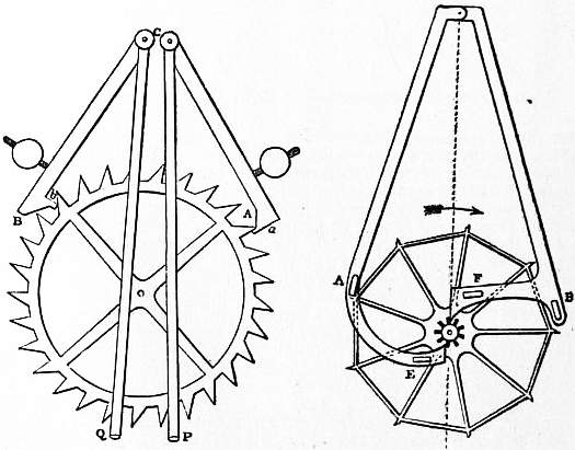
Fig. 17.—Mudge’s Gravity Escapement. Fig. 18.—Bloxam’s Gravity Escapement.
The next kind of remontoire still leaves the scape-wheel linked up with the clock-train, but makes it wind up the pallets which are held raised up till their action is wanted, when they are allowed to drop gently on the crutch or the pendulum rod. In this case the Gravity escapements. two arms of the anchor are usually divided and mounted on separate shafts so as to act independently. This idea was first started by Thomas Mudge (1717-1794) and Alexander Cumming (1733-1814). Mudge’s escapement is shown in fig. 17. The tooth A of the scape-wheel is resting against the stop or detent a at the end of the pallet CA, from the axis or arbor of which descends the half-fork CP to touch the pendulum. From the other pallet CB descends the other half-fork CO. The two arbors are set as near the point of suspension, or top of the pendulum spring, as possible. The pendulum, as here represented, must be moving to the right, and just leaving contact with the left pallet and going to take up the right one; as soon as it has raised that pallet a little it will evidently unlock the wheel and let it turn, and then the tooth B will raise the left pallet until it is caught by the stop b on that pallet, and then it will stay until the pendulum returns and releases it by raising that pallet still higher. Each pallet therefore descends with the pendulum to a lower point than that where it is taken up, and the difference between them is supplied by the lifting of each pallet by the clock, which does not act on the pendulum at all; so that the pendulum is independent of all variations of force and friction in the train. This escapement is said by Lord Grimthorpe, in his Rudimentary Treatise on Clocks, first published in 1850, to be liable to trip, the pallets being apt to be jerked by the pendulum, so that the teeth slip past the hook, and the wheel flies round. This, however, appears entirely a matter of construction. The really weak point is that while the impulses on the pendulum due to the gravitational fall of the arms are uniform, the force which has to be exercised by the pendulum in unlocking them from the scape-wheel varies with the pressure of the clock-train. Hence we miss the compensation which is so beautiful a result of Graham’s escapement. To avoid this, J. M. Bloxam, a barrister, proposed about the middle of the 19th century his legged gravity escapement (fig. 18). By this arrangement the parts of the scape-wheel which lifted the gravity arms were brought as near to the axis of the scape-wheel as possible, while the locking arms were brought as far from the axis as possible so that the pressure should be light. The pallet arbors were cranked, to embrace the pendulum-spring, so that their centres of motion might coincide with that of the pendulum as nearly as possible—perhaps an unnecessary refinement; at least the three-legged and four-legged gravity escapements answer very well with the pallet arbors set on each side of the top of the spring. The size of the wheel determines the length of the pallets, as they must be at such an angle to each other that the radii of the wheel when in contact with each stop may be at right angles to the pallet arm; and therefore, for a wheel of this size, the depth of locking can only be very small. The pinion in Bloxam’s clock only raises the pallet through 40′ at each beat; i.e. the angle which we call γ, viz. the amplitude of the pendulum when it begins to lift the pallet, is only 20′; and probably, if it were increased to anything like a/√2, where a is the semiarc of swing, the escapement would trip immediately. The two broad pins marked E, F, are the fork-pins, and A and B are the stops. The clock which Bloxam had went very well; but it had an extremely fine train, with pinions of 18; and nobody else appears to have been able to make one to answer.