VOLUME VI SLICE V Clervaux to Cockade (continued 8)
Reading edition
In Table V. below column I. shows the quantity of coal still remaining unworked in the different coalfields at depths not exceeding 4000 ft. and in seams not less than 1 ft. thick, as estimated by seven district commissioners; column II. the total estimated reductions on account of loss in working due to faults and other natural causes in seams and of coal required to be left for barriers, support of surface buildings, &c.; and column III. the estimated net available amount remaining unworked.
Table V.
District. Coalfield. I. II. III.
A. South Wales and Monmouthshire 33,443,000,339 6,972,003,760 26,470,996,579
Somersetshire and part of Gloucestershire No details No details 4,198,301,099
Forest of Dean 305,928,137 47,394,690 258,533,447
B. North Stafford 5,267,833,074 89,782,727 4,368,050,347
South Stafford 1,953,627,435 538,179,363 1,415,448,072
Warwickshire 1,448,804,556 321,822,653 1,126,981,903
Leicestershire 2,467,583,205 642,124,654 1,825,458,551
Shropshire 369,174,620 48,180,921 320,993,699
C. Lancashire 5,349,554,437 1,111,046,710 4,238,507,727
Cheshire 358,998,172 87,165,901 291,832,271
North Wales 2,513,026,200 776,558,371 1,736,467,829
D. Yorkshire No details No details 19,138,006,395
Derby and Notts No details No details 7,360,725,100
E. Northumberland 7,040,348,127 1,530,722,486 5,509,625,641
Cumberland 2,188,938,830 661,230,025 1,527,708,805
Durham 6,607,700,522 1,336,584,176 5,271,116,346
F. Scotland 21,259,767,661 5,579,311,305 15,681,456,356
G. Ireland No details No details 174,458,000
As regards the duration of British coal resources, the commissioners reported (1905):—
“This question turns chiefly upon the maintenance or the variation of the annual output. The calculations of the last Coal Commission as to the future exports and of Mr Jevons as to the future annual consumption make us hesitate to prophesy how long our coal resources are likely to last. The present annual output is in round numbers 230 million tons, and the calculated available resources in the proved coalfields are in round numbers 100,000 million tons, exclusive of the 40,000 million tons in the unproved coalfields, which we have thought best to regard only as probable or speculative. For the last thirty years the average increase in the output has been 2½% per annum, and that in the exports (including bunkers) 4½% per annum. It is the general opinion of the District Commissioners that owing to physical considerations it is highly probable that the present rate of increase of the output of coal can long continue—indeed, they think that some districts have already attained their maximum output, but that on the other hand the developments in the newer coalfields will possibly increase the total output for some years.
In view of this opinion and of the exhaustion of the shallower collieries we look forward to a time, not far distant, when the rate of increase of output will be slower, to be followed by a period of stationary output, and then a gradual decline.”
According to a calculation made by P. Frech in 1900, on the basis of the then rate of production, the coalfields of central France, central Bohemia, the kingdom of Saxony, the Prussian province of Saxony and the north of England, would be exhausted in 100 to 200 years, the other British coalfields, the Waldenburg-Schatzlar and that of the north of France in 250 years, those of Saarbrücken, Belgium, Aachen and Westphalia in 600 to 800 years, and those of Upper Silesia in more than 1000 years.
(O. J. R. H.; H. M. R.)
Coal-Mining.
The opening and laying out, or, as it is generally called, “winning,” of new collieries is rarely undertaken without a preliminary examination Preliminary trial of coalworkings. of the character of the strata by means of borings, either for the purpose of determining the number and nature of the coal seams in new ground, or the position of the particular seam or seams which it is proposed to work in extensions of known coalfields.
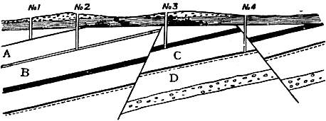
Fig. 1.—Proving by Boreholes.
The principle of proving a mineral field by boring is illustrated by fig. 1, which represents a line direct from the dip to the rise of the field, the inclination of the strata being one in eight. No. 1 bore is commenced at the dip, and reaches a seam of coal A, at 40 fathoms; at this depth it is considered proper to remove nearer to the outcrop so that lower strata may be bored into at a less depth, and a second bore is commenced. To find the position of No. 2, so as to form a continuous section, it is necessary to reckon the inclination of the strata, which is 1 in 8; and as bore No. 1 was 40 fathoms in depth, we multiply the depth by the rate of inclination, 40 × 8 = 320 fathoms, which gives the point at which the coal seam A should reach the surface. But there is generally a certain depth of alluvial cover which requires to be deducted, and which we call 3 fathoms, then (40 - 3 = 37) × 8 = 296 fathoms; or say 286 fathoms is the distance that the second bore should be placed to the rise of the first, so as to have, for certain, the seam of coal A in clear connexion with the seam of coal B. In bore No. 3, where the seam B, according to the same system of arrangement, should have been found at or near the surface, another seam C is proved at a considerable depth, differing in character and thickness from either of the preceding. This derangement being carefully noted, another bore to the outcrop on the same principle is put down for the purpose of proving the seam C; the nature of the strata at first is found to agree with the latter part of that bored through in No. 3, but immediately on crossing the dislocation seen in the figure it is changed and the deeper seam D is found.
The evidence therefore of these bores (3 and 4) indicates some material derangement, which is then proved by other bores, either towards the dip or the outcrop, according to the judgment of the borer, so as to ascertain the best position for sinking pits. (For the methods of boring see Boring.)
The working of coal may be conducted either by means of levels or galleries driven from the outcrop in a valley, or by shafts or pits sunk from the surface. In the early days of coal-mining, open working, or quarrying from Methods of working. the outcrop of the seams, was practised to a considerable extent; but there are now few if any places in England where this can be done. In 1873 there could be seen, in the thick coal seams of Bengal, near Raniganj, a seam about 50 ft. thick laid bare, over an area of several acres, by stripping off a superficial covering varying from 10 to 30 ft., in order to remove the whole of the coal without loss by pillars. Such a case, however, is quite exceptional. The operations by which the coal is reached and laid out for removal are known as “winning,” the actual working or extraction of the coal being termed “getting.” In fig. 2 A B is a cross cut level, by which the seams of coal 1 and 2 are won, and C D a vertical shaft by which the seams 1, 2 and 3 are won. When the field is won by the former method, the coal lying above the level is said to be “level-free.” The mode of winning by level is of less general application than that by shafts, as the capacity for production is less, owing to the smaller size of roadways by which the coal must be brought to the surface, levels of large section being expensive and difficult to keep open when the mine has been for some time at work. Shafts, on the other hand, may be made of almost any capacity, owing to the high speed in drawing which is attainable with proper mechanism, and allow of the use of more perfect arrangements at the surface than can usually be adopted at the mouth of a level on a hill-side. A more cogent reason, however, is to be found in the fact that the principal coalfields are in flat countries, where the coal can only be reached by vertical sinking.
The methods adopted in driving levels for collieries are generally similar to those adopted in other mines. The ground is secured by timbering, or more usually by arching in masonry or brick-work. Levels like that in fig. 2, which are driven across the stratification, or generally anywhere not in coal, are known as “stone drifts.” The sinking of colliery shafts, however, Sinking of shafts. differs considerably from that of other mines, owing to their generally large size, and the difficulties that are often encountered from water during the sinking. The actual coal measure strata, consisting mainly of shales and clays, are generally impervious to water, but when strata of a permeable character are sunk through, such as the magnesian limestone of the north of England, the Permian sandstones of the central counties, or the chalk and greensand in the north of France and Westphalia, special methods are required in order to pass the water-bearing beds, and to protect the shaft and workings from the influx of water subsequently. Of these Tubbing. methods one of the chief is the plan of tubbing, or lining the excavation with an impermeable casing of wood or iron, generally the latter, built up in segments forming rings, which are piled upon each other throughout the whole depth of the water-bearing strata. This method necessitates the use of very considerable pumping power during the sinking, as the water has to be kept down in order to allow the sinkers to reach a water-tight stratum upon which the foundation of the tubbing can be placed. This consists of a heavy cast iron ring, known as a wedging crib, or curb, also fitted together in segments, which is lodged in a square-edged groove cut for its reception, tightly caulked with moss, and wedged into position. Upon this the tubbing is built up in segments, of which usually from 10 to 12 are required for the entire circumference, the edges being made perfectly true. The thickness varies according to the pressure expected, but may be taken at from ¾ to 1½ in. The inner face is smooth, but the back is strengthened with angle brackets at the corners. A small hole is left in the centre of each segment, which is kept open during the fitting to prevent undue pressure upon any one, but is stopped as soon as the circle is completed. In the north of France and Belgium wooden tubbings, built of polygonal rings, were at one time in general use. The polygons adopted were of 20 or more sides approximating to a circular form.
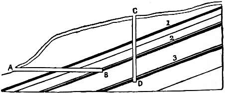
Fig. 2.—Shaft and Level.
The second principal method of sinking through water-bearing ground is by compressed air. The shaft is lined with a cylinder of wrought iron, within which a tubular chamber, provided with doors above and below, known as an Pneumatic sinking. air-lock, is fitted by a telescopic joint, which is tightly packed so as to close the top of the shaft air-tight. Air is then forced into the inclosed space by means of a compressing engine, until the pressure is sufficient to oppose the flow of water into the excavation, and to drive out any that may collect in the bottom of the shaft through a pipe which is carried through the air-sluice to the surface. The miners work in the bottom in the same manner as divers in an ordinary diving-bell. Access to the surface is obtained through the double doors of the air-sluice, the pressure being reduced to that of the external atmosphere when it is desired to open the upper door, and increased to that of the working space below when it is intended to communicate with the sinkers, or to raise the stuff broken in the bottom. This method has been adopted in various sinkings on the continent of Europe.
The third method of sinking through water-bearing strata is that of boring, adopted by Messrs Kind & Chaudron in Belgium and Germany. For this purpose a horizontal bar armed with vertical cutting chisels is used, which cuts Shaft boring. out the whole section of the shaft simultaneously. In the first instance, a smaller cutting frame is used, boring a hole from 3 to 5 ft. in diameter, which is kept some 50 or 60 ft. in advance, so as to receive the detritus, which is removed by a shell pump of large size. The large trepan or cutter weighs about 16 tons, and cuts a hole of from 9 to 15 ft. in diameter. The water-tight lining may be either a wrought iron tube, which is pressed down by jack screws as the borehole advances, or cast iron tubbing put together in short complete rings, in contradistinction to the old plan of building them up of segments. The tubbing, which is considerably less in diameter than the borehole, is suspended by rods from the surface until a bed suitable for a foundation is reached, upon which a sliding length of tube, known as the moss box, bearing a shoulder, which is filled with dried moss, is placed. The whole weight of the tubbing is made to bear on the moss, which squeezes outwards, forming a completely water-tight joint. The interval between the back of the tubbing and the sides of the borehole is then filled up with concrete, which on setting fixes the tubbing firmly in position. With increase in depth, however, the thickness and weight of the cast iron tubbing in a large shaft become almost unmanageable; in one instance, at a depth of 1215 ft., the bottom rings in a shaft 14½ ft. in diameter are about 4 in. thick, which is about the limit for sound castings. It has therefore been proposed, for greater depths, to put four columns of tubbings of smaller diameters, 8½ and 5½ ft., in the shaft, and fill up the remainder of the boring with concrete, so that with thinner and lighter castings a greater depth may be reached. This, however, has not as yet been tried. Another extremely useful method of sinking through water-bearing ground, introduced by Messrs A. & H. T. Poetsch in 1883, and originally applied to shafts passing through quicksands above brown coal seams, has been applied with advantage in opening new pits through the secondary and tertiary strata above the coal measures in the north of France and Belgium, some of the most successful examples being those at Lens, Anzin and Vicq, in the north of France basin. In this system the soft ground or fissured water-bearing rock is rendered temporarily solid by freezing the contained water within a surface a few feet larger in diameter than the size of the finished shaft, so that the ground may be broken either by hand tools or blasting in the same manner as hard rock. The miners are protected by the frozen wall, which may be 4 or 5 ft. thick. The freezing is effected by circulating brine (calcium chloride solution) cooled to 5° F. through a series of vertical pipes closed at the bottom, contained in boreholes arranged at equal distances apart around the space to be frozen, and carried down to a short distance below the bottom of the ground to be secured. The chilled brine enters through a central tube of small diameter, passes to the bottom of the outer one and rises through the latter to the surface, each system of tubes being connected above by a ring main with the circulating pumps. The brine is cooled in a tank filled with spiral pipes, in which anhydrous ammonia, previously liquefied by compression, is vaporized in vacuo at the atmospheric temperature by the sensible heat of the return-current of brine, whose temperature has been slightly raised in its passage through the circulating tubes. When hard ground is reached, a seat is formed for the cast iron tubbing, which is built up in the usual way and concreted at the back, a small quantity of caustic soda being sometimes used in mixing the concrete to prevent freezing. In an application of this method at Vicq, two shafts of 12 and 16.4 ft. diameter, in a covering of cretaceous strata, were frozen to a depth of 300 ft. in fifty days, the actual sinking and lining operations requiring ninety days more. The freezing machines were kept at work for 200 days, and 2191 tons of coal were consumed in supplying steam for the compressors and circulating pumps.
The introduction of these special methods has considerably simplified the problem of sinking through water-bearing strata. Some of the earlier sinkings of this kind, when pumps had to be depended on for keeping down the water, were conducted at great cost, as, for instance, at South Hetton, and more recently Ryhope, near Sunderland, through the magnesian limestone of Durham.
The size and form of colliery shafts vary in different districts. In the United States and Scotland rectangular pits secured by timber framings are still common, but the tendency is now generally to make them round, 20 ft. being about Size of shafts. the largest diameter employed. In the Midland counties, from 7 to 9 ft. is a very common size, but larger dimensions are adopted where a large production is required. Since the accident at Hartley colliery in 1862, caused by the breaking of the pumping-engine beam, which fell into the shaft and blocked it up, whereby the whole of the men then at work in the mine were starved to death, it has been made compulsory upon mine-owners in the United Kingdom to have two pits for each working, in place of the single one divided by walls or brattices which was formerly thought sufficient. The use of two independent connexions—whether separate pits or sections of the same pit, between the surface and the workings—is necessary for the service of the ventilation, fresh air from the surface being carried down one, known as the “downcast,” while the foul or return air of the mine rises through the other or “upcast” pit back to the surface. In a heavily-watered mine it is often necessary to establish a special engine-pit, with pumps permanently fixed, or a division of one of the pits may be devoted to this purpose. The pumps, placed close to the point where the water accumulates, may be worked by an engine on the surface by means of heavy reciprocating rods which pass down the shaft, or by underground motors driven by steam, compressed air or electricity.
Where the water does not accumulate very rapidly it is a common practice to allow it to collect in a pit or sump below the working bottom of the shaft, and to draw it off in a water tub or “hoppet” by the main engine, when the latter is not employed in raising coal.
The laying out of a colliery, after the coal has been won, by sinkings or levels, may be accomplished in various ways, according to the nature of the coal, its thickness and dip, and the extent of ground to be worked. In the South Laying out workings. Staffordshire and other Midland coalfields, where only shallow pits are required, and the coals are thick, a pair of pits may be sunk for a very few acres, while in the North of England, on the other hand, where sinking is expensive, an area of some thousands of acres may be commanded from the same number of pits. In the latter case, which represents the most approved practice, the sinking is usually placed about the centre of the ground, so that the workings may radiate in every direction from the pit bottom, with the view of employing the greatest number of hands to advantage. Where a large area cannot be commanded, it is best to sink to the lowest point of the field for the convenience of drawing the coal and water which become level-free in regard to the pit. Where properties are much divided, it is always necessary to maintain a thick barrier of unwrought coal between the boundary of the mine and the neighbouring workings, especially if the latter are to the dip. If a prominent line of fault crosses the area it may usually be a convenient division of the fields into sections or districts. The first process in laying out the workings consists in driving a gallery on the level along the course of the coal seam, which is known as a “dip head level,” and a lower parallel one, in which the water collects, known as a “lodgment level.” Galleries driven at right angles to these are known as a “dip” or “rise headings,” according to their position above or below the pit bottom. In Staffordshire the main levels are also known as “gate roads.” To secure the perpendicularity of the shaft, it is necessary to leave a large mass or pillar of the seam untouched around the pit bottom. This pillar is known in Scotland as the “pit bottom stoop.” The junction of the levels with the pit is known as the “pit eye”; it is usually of an enlarged section, and lined with masonry or brick-work, so as to afford room for handling the wagons or trams of coal brought from the working faces. In this portion of the pit are generally placed the furnaces for ventilation, and the boilers required for working steam engines underground, as well as the stables and lamp cabin.
The removal of the coal after the roads have been driven may be effected in many different ways, according to the custom of the district. These may, however, all be considered as modifications of two systems, viz. pillar work Method of working coal. and long-wall work. In the former which is also known as “post and stall” or “bord and pillar” in the north of England, “pillar and stall” in South Wales, and “stoop and room” in Scotland, the field is divided into strips by numerous openings driven parallel to the main rise headings, called “bords” or “bord gates,” which are again divided by cutting through them at intervals, so as to leave a series of Pillar working. pillars arranged chequer-wise over the entire area. These pillars are left for the support of the roof as the workings advance, so as to keep the mine open and free from waste. In the oldest form of this class of working, where the size of the pillar is equal to the width of the stall or excavation, about ¾ of the whole seam will be removed, the remainder being left in the pillars. A portion of this may be got by the process known as robbing the pillars, but the coal so obtained is liable to be very much crushed from the pressure of the superincumbent strata. This crushing may take place either from above or below, producing what are known as “creeps” or “sits.”
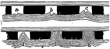
Fig 3.—“Creeps” in Coal-Mines.
A coal seam with a soft pavement and a hard roof is the most subject to a “creep.” The first indication is a dull hollow sound heard when treading on the pavement or floor, probably occasioned by some of the individual layers parting from each other as shown at a fig. 3; the succeeding stages of creep are shown at b, c, d, f, and g, in the same figure; the last being the final stage, when the coal begins to sustain the pressure from the overlying strata, in common with the disturbed pavement.
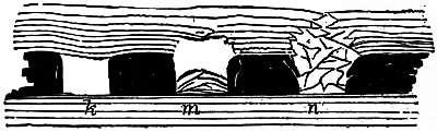
Fig. 4.—“Sits” in Mines.
“Sits” are the reverse of creeps; in the one case the pavement is forced up, and in the other the roof is forced or falls down, for want of proper support or tenacity in itself. This accident generally arises from an improper size of pillars; some roofs, however, are so difficult to support that sits take place where the half of the coal is left in pillars. Fig. 4 will convey a general idea of the appearance of sits,—k, m, n showing different stages.
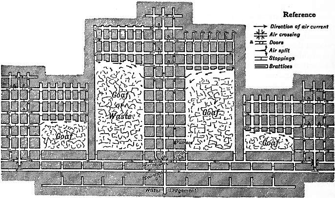
Fig. 5.—Pillar Working.
The modern method of pillar working is shown in fig. 5. In the Northumberland steam coal district, where it is carried out in the most perfect manner, the bords are 5 to 6 yds. in width, while the pillars are 22 yds. broad and 30 yds. long, which are subsequently got out on coming back. In the same figure is also shown the method of working whole coal and pillars at the same time, a barrier of two or three ranges of pillars or a rib of solid coal being left between the working in the solid and those in the pillars. The space from which the entire quantity of coal has been removed is known in different districts as the “goaf,” “gob,” or “waste.”
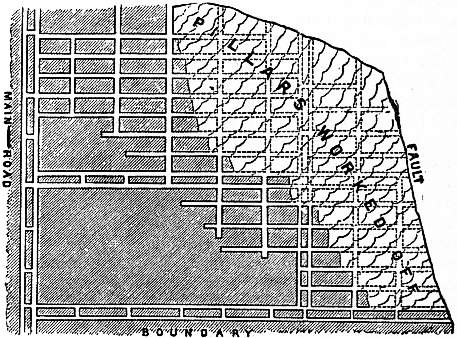
Fig. 6.—Lancashire method of working Coal.
Fig. 6 represents the Lancashire system of pillar working. The area is laid out by two pairs of level drifts, parallel to each other, about 150 yds. apart, which are carried to the boundary. About 100 yds. back from the boundary a communication is made between these levels, from which other levels are driven forward, dividing the coal into ribs of about 25 or 30 yds. wide, which are then cut back by taking off the coal in slices from the level towards the rise in breadths of about 6 yds. By this method the whole of the coal is got backwards, the main roads being kept in solid coal; the intermediate levels not being driven till they are wanted, a greater amount of support is given, and the pillars are less crushed than is usual in pillar working.
In the South Wales system of working, cross headings are driven from the main roads obliquely across the rise to get a sufficiently easy gradient for horse roads, and from these the stalls are opened out with a narrow entrance, in order to leave support on either side of the road, but afterwards widening to as great a breadth as the seam will allow, leaving pillars of a minimum thickness. The character of such workings is very irregular in plan, and as the ventilation is attended with considerable difficulty, it is now becoming generally superseded by more improved methods.
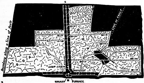
Fig. 7.—Long-wall method of working Coal in Derbyshire.
The second great principle of working is that known as long-wall or long-work, in which the coal is taken away either in broad faces from roads about 40 or 50 yds. apart and parallel to each other, or along curved faces between roads Long-wall working. radiating from the pit bottom—the essential feature in both cases being the removal of the whole of the coal at once, without first sub-dividing it into pillars, to be taken away at a second working. The roof is temporarily supported by wooden props or pack walling of stone, for a sufficient breadth along the face to protect the workmen, and allow them to work together behind. The general character of a long-wall working is shown in fig. 7, which represents an area of about 500 acres of the bottom hard steam coal at Shipley in Derbyshire. The principal road extends from the shafts southward; and on both sides of it the coal has been removed from the light-shaded area by cutting it back perpendicularly towards the boundaries, along faces about 50 yds. in length, those nearest to the shaft being kept in advance of those farther away, producing a step-shaped outline to the face of the whole coal. It will be seen that by this method the whole of the seam, with the exception of the pillars left to protect the main roadways, is removed. The roads for drawing the coal from the working faces to the shaft are kept open by walling through the waste or goaf produced by the fall of the unsupported roof. The straight roads are the air-ways for carrying pure air from the down-cast shaft to the working faces, while the return air passes along the faces and back to the up-cast by the curved road. The above is the method of working long-wall forward, i.e. taking the coal in advance from the pit towards the boundary, with roads kept open through the gob. Another method consists in driving towards the boundary, and taking the coal backward towards the shafts, or working homeward, allowing the waste to close up without roads having to be kept open through it. This is of course preferable, but is only applicable where the owner of the mine can afford to expend the capital required to reach the limit of the field in excess of that necessary when the raising of coal proceeds pari passu with the extension of the main roads. Fig. 6 is substantially a modification of this kind of long-wall work. South Yorkshire method. Fig. 8 represents a method of working practised in the South Yorkshire district, known as bords and banks. The field is divided by levels and headings into rectangular banks, while from the main levels bords or wickets about 30 yds. wide, separated from each other by banks of about the same width, are carried forward in long-wall work, as shown on the left side of the figure, the waste being carefully packed behind so as to secure the ventilation. When these have been worked up to the extremity, as shown on the right side, the intermediate bank is removed by working backward towards the level. This system, therefore, combines both methods of long-wall working, but it is not generally applicable, owing to the difficulty of ventilation, due to the great length of air-way that has to be kept open around the waste on each bank.
The relative advantages of the different methods may be generally stated as follows. Long-wall work is best suited for thin coals, and those having a good roof, i.e. one that gives way gradually and fills up the excavation made by removing the coal without scaling off suddenly and falling into the working faces, when practically the whole of the coal may be removed. Against these advantages must be placed the difficulties attending the maintenance of roads through the goaves, and in some cases the large proportion of slack to round or large coal obtained. Pillar working, in the whole coal, is generally reputed to give a more advantageous proportion of round coal to slack, the latter being more abundantly produced on the removal of the pillars, but as these form only a small portion of the whole seam, the general yield is more advantageous than in the former method. The ventilation of pillar working is often attended with difficulty, and the coal is longer exposed to the influence of the air, a point of importance in some coals, which deteriorate in quality when exposed to a hot damp atmosphere. The great increase in the size of the pillars in the best modern collieries worked upon this principle has, however, done much to approximate the two systems to an equality in other respects.
Where the whole of the coal is removed at once there is less chance of surface damage, when the mines are deep, than with pillar workings. A notable instance of this was afforded at Newstead, Notts, where the ruined front of Newstead Abbey was lowered several feet without any injury to the structure.
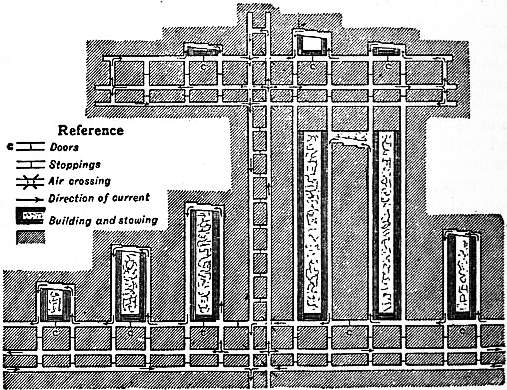
Fig. 8.—Bords and Banks.
The working of very thick seams presents certain special peculiarities, owing to the difficulties of supporting the roof in the excavated portions, and supplying fresh air to the workings. The most typical example of this kind of Working thick seams. working in England is afforded by the thick coal of South Staffordshire, which consists of a series of closely associated coal seams, varying from 8 to 12 or 13, divided from each other by their partings, but making together one great bed of from 25 to 40 ft. or more in thickness. The partings together do not amount to more than 2 or 3 ft. The method of working which has been long in use is represented in fig. 9. The main level or gate road is driven in the benches coal, or lower part of the seam, while a smaller drift for ventilation, called an air heading, is carried above it in one of the upper beds called the slipper coal. From the gate road a heading called a bolt-hole is opened, and extended into a large rectangular chamber, known as a “side of work,” large pillars being left at regular intervals, besides smaller ones or cogs. The order in which the coal is cut is shown in the dotted and numbered squares in the figure. The coal is first cut to the top of the slipper coal from below, after which the upper portion is either broken down by wedging or falls of itself. The working of these upper portions is exceedingly dangerous, owing to the great height of the excavations, and fatal accidents from falls of roof are in consequence more common in South Staffordshire than in any other coalfield in this country. The air from the down-cast shaft enters from the gate road, and passes to the up-cast through the air heading above. About one-half of the total coal (or less) is obtained in the first working; the roof is then allowed to fall, and when the gob is sufficiently consolidated, fresh roads are driven through it to obtain the ribs and pillars left behind by a second or even, in some cases, a third working. The loss of coal by this method is very considerable, besides great risk to life and danger from fire. It has, therefore, been to some extent superseded by the long-wall method, the upper half being taken at the first working, and removed as completely as possible, working backwards from the boundaries to the shaft. The lower half is then taken in the same manner, after the fallen roof has become sufficiently consolidated to allow the mine to be re-opened.
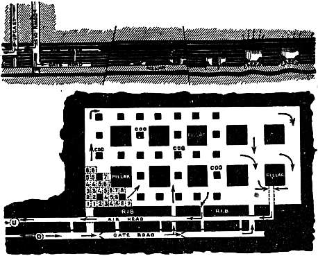
Fig. 9.—South Staffordshire method of working Thick Coal.
In the working of thick seams inclined at a high angle, such as those in the south of France, and in the lignite mines of Styria and Bohemia, the method of working in horizontal slices, about 12 or 15 ft. thick, and filling up the excavation with broken rock and earth from the surface, is now generally adopted in preference to the systems formerly used. At Monceaux les Mines, in France, a seam 40 ft. thick, and dipping at an angle of 20°, is worked in the following manner. A level is driven in a sandstone forming the floor, along the course of the coal, into which communications are made by cross cuts at intervals of 16 yds., which are driven across to the roof, dividing up the area to be worked into panels. These are worked backwards, the coal being taken to a height of 20 ft., the opening being packed up with stone sent down from the surface. As each stage is worked out, the floor level is connected with that next below it by means of an incline, which facilitates the introduction of the packing material. Stuff containing a considerable amount of clay is found to be the best suited for the purpose of filling, as it consolidates readily under pressure.
In France and Germany the method of filling the space left by the removal of the coal with waste rock, quarried underground or sent down from the surface, which was originally used in connexion with the working of thick inclined seams by the method of horizontal slices, is now largely extended to long-wall workings on thin seams, and in Westphalia is made compulsory where workings extend below surface buildings, and safety pillars of unwrought coal are found to be insufficient. With careful packing it is estimated that the surface subsidence will not exceed 40% of the thickness of the seam removed, and will usually be considerably less. The material for filling may be the waste from earlier workings stored in the spoil banks at the surface; where there are blast furnaces in the neighbourhood, granulated slag mixed with earth affords excellent packing. In thick seams packing adds about 5d. per ton to the cost of the coal, but in thinner seams the advantage is on the other side.
In some anthracite collieries in America the small coal or culm and other waste are washed into the exhausted workings by water which gives a compact mass filling the excavation when the water has drained away. A modification of this method, which originated in Silesia, is now becoming of importance in many European coalfields. In this the filling material, preferably sand, is sent down from the surface through a vertical steel pipe mixed with sufficient water to allow it to flow freely through distributing pipes in the levels commanding the excavations to be filled; these are closed at the bottom by screens of boards sufficiently close to retain the packing material while allowing the water to pass by the lower level to the pumping-engine which returns it to the surface.
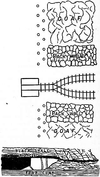
Fig. 10.—Long-wall working-face—Plan and Section.
The actual cutting of the coal is chiefly performed by manual labour, the tool employed being a sharp-pointed double-armed pick, which is nearly straight, except when required for use in hard rock, when the arms are made with an Methods of cutting coal. inclination or “anchored.” The terms pike, pick, mandril and slitter are applied to the collier’s pick in different districts, the men being known as pikemen or hewers. In driving levels it is necessary to cut grooves vertically parallel to the walls, a process known as shearing; but the most important operation is that known as holing or kirving, which consists in cutting a notch or groove in the floor of the seam to a depth of about 3 ft., measured back from the face, so as to leave the overhanging part unsupported, which then either falls of its own accord within a few hours, or is brought down either by driving wedges along the top, or by blasting. The process of holing in coal is one of the severest kinds of human labour. It has to be performed in a constrained position, and the miner lying on his side has to cut to a much greater height, in order to get room to carry the groove in to a sufficient depth, than is required to bring the coal down, giving rise to a great waste in slack as compared with machine work. This is sometimes obviated by holing in the beds below the coal, or in any portion of a seam of inferior quality that may not be worth working. This loss is proportionately greater in thin than in thick seams, the same quantity being cut to waste in either case. The method of cutting coal on the long-wall system is seen in fig. 10, representing the working at the Shipley colliery. The coal is 40 in. thick, with a seam of fire-clay and a roof of black shale; about 6 in. of the upper part, known as the roof coal, not being worth working, is left behind. A groove of triangular section of 30 in. base and 9 in. high is cut along the face, inclined timber props being placed at intervals to support the overhanging portion until the required length is cut. These are then removed, and the coal is allowed to fall, wedges or blasting being employed when necessary. The roof of the excavation is supported as the coal is removed, by packing up the waste material, and by a double row of props, 2 ft. from each other, placed temporarily along the face. These are placed 5 ft. apart, the props of the back row alternating with those in front. The props used are preferably of small oak or English larch, but large quantities of fir props, cut to the right length, are also imported from the north of Europe. As the work proceeds onwards, the props are withdrawn and replaced in advance, except those that may be crushed by the pressure or buried by sudden falls of the roof.
In Yorkshire hollow square pillars, formed by piling up short blocks of wood or chocks, are often used instead of props formed of a single stem.
In securing the roof and sides of coal workings, malleable iron and steel are now used to some extent instead of timber, although the consumption of the latter material is extremely large. As a substitute for timber props at the face, pieces of steel joists, with the web cut out for a short distance on either end, with the flanges turned back to give a square bearing surface, have been introduced. In large levels only the cap pieces for the roof are made of steel joists, but in smaller ones complete arches made of pieces of rails fish-jointed at the crown are used. In another system introduced by the Mannesmann Tube Company the prop is made up of weldless steel tubes sliding telescopically one within the other, which are fixed at the right height by a screw clamp capable of carrying a load of 15 to 16 tons. These can be most advantageously used on thick seams 6 to 10 ft. or upwards. For shaft linings steel rings of H or channel section supported by intermediate struts are also used, and cross-bearers or buntons of steel joists and rail guides are now generally substituted for wood.
When the coal has been under-cut for a sufficient length, the struts are withdrawn, and the overhanging mass is allowed to fall during the time that the workmen are out of the pit, or it may be brought down by driving wedges, or if it be of a compact character a blast in a borehole near the roof may be required. Sometimes, but rarely, it happens that it is necessary to cut vertical grooves in the face to determine the limit of the fall, such limits being usually dependent upon the cleet or divisional planes in the coal, especially when the work is carried perpendicular to them or on the end.
The substitution of machinery for hand labour in cutting coal has long been a favourite problem with inventors, the earliest plan being that of Michael Meinzies, in 1761, who proposed to work a heavy pick underground by power Coal-cutting machines. transmitted from an engine at the surface, through the agencies of spear-rods and chains passing over pulleys; but none of the methods suggested proved to be practically successful until the general introduction of compressed air into mines furnished a convenient motive power, susceptible of being carried to considerable distances without any great loss of pressure. This agent has been applied in various ways, in machines which either imitate the action of the collier by cutting with a pick or make a groove by rotating cutters attached to an endless chain or a revolving disk or wheel. The most successful of the first class, or pick machines, that of William Firth of Sheffield, consists essentially of a horizontal pick with two cutting arms placed one slightly in advance of the other, which is swung backwards and forwards by a pair of bell crank levers actuated by a horizontal cylinder engine mounted on a railway truck. The weight is about 15 cwt. At a working speed of 60 yds. per shift of 6 hours, the work done corresponds to that of twelve average men. The width of the groove cut is from 2 to 3 in. at the face, diminishing to 1½ in. at the back, the proportion of waste being very considerably diminished as compared with the system of holing by hand. The use of this machine has allowed a thin seam of cannel, from 10 to 14 in. in thickness, to be worked at a profit, which had formerly been abandoned as too hard to be worked by hand-labour. Pick machines have also been introduced by Jones and Levick, Bidder, and other inventors, but their use is now mostly abandoned in favour of those working continuously.
In the Gartsherrie machine of Messrs Baird, the earliest of the flexible chain cutter type, the chain of cutters works round a fixed frame or jib projecting at right angles from the engine carriage, an arrangement which makes it necessary to cut from the end of the block of coal to the full depth, instead of holing into it from the face. The forward feed is given by a chain winding upon a drum, which hauls upon a pulley fixed to a prop about 30 yds. in advance. This is one of the most compact forms of machine, the smaller size being only 20 in. high. With an air pressure of from 35 to 40 ℔. per sq. in., a length of from 300 to 350 ft. of coal is holed, 2 ft. 9 in. deep, in the shift of from 8 to 10 hours. The chain machine has been largely developed in America in the Jeffrey, Link Bell, and Morgan Gardner coal cutters. These are similar in principle to the Baird machine, the cutting agent being a flat link chain carrying a double set of chisel points, which are drawn across the coal face at the rate of about 5 ft. per second; but, unlike the older machines, in which the cutting is done in a fixed plane, the chain with its motor is made movable, and is fed forward by a rack-and-pinion motion as the cutting advances, so that the cut is limited in breadth (3½ to 4 ft.), while its depth may be varied up to the maximum travel (8 ft.) of the cutting frame. The carrying frame, while the work is going on, is fixed in position by jack-screws bearing against the roof of the seam, which, when the cut is completed, are withdrawn, and the machine shifted laterally through a distance equal to the breadth of the cut and fixed in position again. The whole operation requires from 8 to 10 minutes, giving a cutting speed of 120 to 150 sq. ft. per hour. These machines weigh from 20 to 22 cwt., and are mostly driven by electric motors of 25 up to 35 h.p. as a maximum. By reason of their intermittent action they are only suited for use in driving galleries or in pillar-and-stall workings.
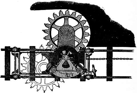
Fig. 11.—Winstanly & Barker’s Coal-cutting Machine—Plan.
A simple form of the saw or spur wheel coal-cutting machine is that of Messrs Winstanly & Barker (fig. 11), which is driven by a pair of oscillating engines placed on a frame running on rails in the usual way. The crank shaft carries a pinion which gears into a toothed wheel of a coarse pitch, carrying cutters at the ends of the teeth. This wheel is mounted on a carrier which, being movable about its centre by a screw gearing worked by hand, gives a radial sweep to the cutting edges. When at work it is slowly turned until the carrier is at right angles to the frame, when the cut has attained the full depth. The forward motion is given by a chain winding upon a crab placed in front, by which it is hauled slowly forward. With 25 ℔ pressure it will hole 3 ft. deep, at the rate of 30 yds. per hour, the cut being only 2¾ in. high, but it will only work on one side of the carriage. This type has been greatly improved and now is the most popular machine in Great Britain, especially in long-wall workings. W. E. Garforth’s Diamond coal cutter, one of the best known, undercuts from 5½ to 6 ft. In some instances electric motors have been substituted for compressed-air engines in such machines.
Another class of percussive coal-cutters of American origin is represented by the Harrison, Sullivan and Ingersoll-Sergeant machines, which are essentially large rock-drills without turning gear for the cutting tool, and mounted upon a pair of wheels placed so as to allow the tool to work on a forward slope. When in use the machine is placed upon a wooden platform inclining towards the face, upon which the miner lies and controls the direction of the blow by a pair of handles at the back of the machine, which is kept stationary by wedging the wheels against a stop on the platform. These machines, which are driven by compressed air, are very handy in use, as the height and direction of the cut may be readily varied; but the work is rather severe to the driver on account of the recoil shock of the piston, and an assistant is necessary to clear out the small coal from the cut, which limits the rate of cutting to about 125 sq. ft. per hour.
Another kind of application of machinery to coal mining is that of Messrs Bidder & Jones, which is intended to replace the use of blasting for bringing down the coal. It consists of a small hydraulic press, which forces a set of expanding Coal-wedging machines. bits or wedges into a bore-hole previously bored by a long screw augur or drill, worked by hand, the action of the press being continued until a sufficient strain is obtained to bring down the coal. The arrangement is, in fact, a modification of the plug and feather system used in stone quarrying for obtaining large blocks, but with the substitution of the powerful rending force of the hydraulic press for hand-power in driving up the wedges. This apparatus has been used at Harecastle in North Staffordshire, and found to work well, but with the disadvantage of bringing down the coal in unmanageably large masses. A method of wedging down coal sufficiently perfected to be of general application would add greatly to the security of colliers.
The removal of the coal broken at the working face to the pit bottom may in small mines be effected by hand labour, but more generally it is done by horse or mechanical traction, upon railways, the “trams” or “tubs,” as the pit Underground conveyance. wagons are called, being where possible brought up to the face. In steeply inclined seams passes or shoots leading to the main level below are sometimes used, and in Belgium iron plates are sometimes laid in the excavated ground to form a slide for the coal down to the loading place. In some instances travelling belts or creepers have been adopted, which deliver the coal with a reduced amount of breakage, but this application is not common. The capacity of the trams varies with the size of the workings and the shaft. From 5 to 7 cwt. are common sizes, but in South Wales they are larger, carrying up to one ton or more. The rails used are of flat bottomed or bridge section varying in weight from 15 to 25 ℔ to the yd.; they are laid upon cross sleepers in a temporary manner, so that they can be easily shifted along the working faces, but are carefully secured along main roads intended to carry traffic continuously for some time. The arrangement of the roads at the face is shown in the plan, fig. 10. In the main roads to the pit when the distance is not considerable horse traction may be used, a train of 6 to 15 vehicles being drawn by one horse, but more generally the hauling or, as it is called in the north of England, the leading of the trains of tubs is effected by mechanical traction.
In a large colliery where the shafts are situated near the centre of the field, and the workings extend on all sides, both to the dip and rise, the drawing roads for the coal may be of three different kinds—(1) levels driven at right angles to the dip, suitable for horse roads, (2) rise ways, known as jinny roads, jig-brows, or up-brows, which, when of sufficient slope, may be used as self-acting planes, i.e. the loaded waggons may be made to pull back the empty ones to the working faces, and (3) dip or down-brows, requiring engine power. A road may be used as a self-acting or gravitating incline when the gradient is 1 in 30 or steeper, in which case the train is lowered by a rope passing over a pulley or brake drum at the upper end, the return empty train being attached to the opposite end of the rope and hauled up by the descending load. The arrangements for this purpose vary, of course, with the amount of work to be done with one fixing of the machinery; where it is likely to be used for a considerable time, the drum and brake are solidly constructed, and the ropes of steel or iron wire carefully guided over friction rollers, placed at intervals between the rails to prevent them from chafing and wearing out on the ground. Where the load has to be hauled up a rising gradient, underground engines, driven by steam or compressed air or electric motors, are used. In some cases steam generated in boilers at the surface is carried in pipes to the engines below, but there is less loss of power when compressed air is sent down in the same way. Underground boilers placed near the up-cast pit so that the smoke and gases help the ventilating furnace have been largely used but are now less favourably regarded than formerly. Water-pressure engines, driven by a column of water equal to the depth of the pit, have also been employed for hauling. These can, however, only be used advantageously where there are fixed pumps, the fall of water generating the power resulting in a load to be removed by the expenditure of an equivalent amount of power in the pumping engine above that necessary for keeping down the mine water.
The principal methods in which power can be applied to underground traction are as follows:—
1. Tail rope system.
2. Endless chain system.
3. Endless rope system on the ground.
4. Endless rope system overhead.
The three last may be considered as modifications of the same principle. In the first, which is that generally used in Northumberland and Durham, a single line of rails is used, the loaded tubs being drawn “out bye,” i.e. towards the shaft, and the empty ones returned “in bye,” or towards the working faces, by reversing the engine; while in the other systems, double lines, with the rope travelling continuously in the same direction, are the rule. On the tail rope plan the engine has two drums worked by spur gearing, which can be connected with, or cast loose from, the driving shaft at pleasure. The main rope, which draws out the loaded tubs, coils upon one drum, and passes near the floor over guide sheaves placed about 20 ft. apart. The tail rope, which is of lighter section than the main one, is coiled on the second drum, passes over similar guide sheaves placed near the roof or side of the gallery round a pulley at the bottom of the plane, and is fixed to the end of the train or set of tubs. When the load is being drawn out, the engine pulls directly on the main rope, coiling it on to its own drum, while the tail drum runs loose paying out its rope, a slight brake pressure being used to prevent its running out too fast. When the set arrives out bye, the main rope will be wound up, and the tail rope pass out from the drum to the end and back, i.e. twice the length of the way; the set is returned in bye, by reversing the engine, casting loose the main, and coupling up the tail drum, so that the tail rope is wound up and the main rope paid out. This method, which is the oldest, is best adapted for ways that are nearly level, or when many branches are intended to be worked from one engine, and can be carried round curves of small radius without deranging the trains; but as it is intermittent in action, considerable engine-power is required in order to get up the required speed, which is from 8 to 10 m. per hour. From 8 to 10 tubs are usually drawn in a set, the ways being often from 2000 to 3000 yds. long. In dip workings the tail rope is often made to work a pump connected with the bottom pulley, which forces the water back to the cistern of the main pumping engine in the pit.
For the endless chain system, which is much used in the Wigan district, a double line of way is necessary, one line for full and the other for empty tubs. The chain passes over a pulley driven by the engine, placed at such a height as to allow it to rest upon the tops of the tubs, and round a similar pulley at the far end of the plane. The forward edge of the tub carries a projecting pin or horn, with a notch into which the chain falls which drags the tub forward. The road at the outer end is made of a less slope than the chain, so that on arrival the tub is lowered, clears the pin, and so becomes detached from the chain. The tubs are placed on at intervals of about 20 yds., the chain moving continuously at a speed of from 2½ to 4 m. per hour. This system presents the greatest advantages in point of economy of driving power, especially where the gradients are variable, but is expensive in first cost, and is not well suited for curves, and branch roads cannot be worked continuously, as a fresh set of pulleys worked by bevel gearing is required for each branch.
The endless rope system may be used with either a single or double line of way, but the latter is more generally advantageous. The rope, which is guided upon sheaves between the rails, is taken twice round the head pulley. It is also customary to use a stretching pulley to keep the rope strained when the pull of the load diminishes. This is done by passing a loop at the upper end round a pulley mounted in a travelling frame, to which is attached a weight of about 15 cwt. hanging by a chain. This weight pulls directly against the rope; so if the latter slacks, the weight pulls out the pulley frame and tightens it up again. The tubs are usually formed into sets of from 2 to 12, the front one being coupled up by a short length of chain to a clamping hook formed of two jaws moulded to the curve of the rope which are attached by the “run rider,” as the driver accompanying the train is called. This system in many respects resembles the tail rope, but has the advantage of working with one-third less length of rope for the same length of way.
The endless rope system overhead is substantially similar to the endless chain. The wagons are attached at intervals by short lengths of chain lapped twice round the rope and hooked into one of the links, or in some cases the chains are hooked into hempen loops on the main rope. In mines that are worked from the outcrop by adits or day levels traction by locomotives driven by steam, compressed air or electricity is used to some extent. The most numerous applications are in America.
One of the most important branches of colliery work is the management of the ventilation, involving as it does the supply of fresh air to the men working in the pit, as well as the removal of inflammable gases that may be given Ventilation. off by the coal. This is effected by carrying through the workings a large volume of air which is kept continually moving in the same direction, descending from the surface by one or more pits known as intake or downcast pits, and leaving the mine by a return or upcast pit. Such a circulation of air can only be effected by mechanical means when the workings are of any extent, the methods actually adopted being—(1) The rarefaction of the air in the upcast pit by a furnace placed at the bottom; and (2) Exhaustion by machinery at the surface. The former plan, being the older, has been most largely used, but is becoming replaced by some form of machine.
The usual form of ventilating furnace is a plain fire grate placed under an arch, and communicating with the upcast shaft by an inclined drift. It is separated from the coal by a narrow passage walled and arched in brickwork on both-sides. The size of the grate varies with the requirements of the ventilation, but from 6 to 10 ft. broad and from 6 to 8 ft. long are usual dimensions. The fire should be kept as thin and bright as possible, to reduce the amount of smoke in the upcast. When the mine is free from gas, the furnace may be worked by the return air, but it is better to take fresh air directly from the downcast by a scale, or split, from the main current. The return air from fiery workings is never allowed to approach the furnace, but is carried into the upcast by a special channel, called a dumb drift, some distance above the furnace drift, so as not to come in contact with the products of combustion until they have been cooled below the igniting point of fire-damp. Where the upcast pit is used for drawing coal, it is usual to discharge the smoke and gases through a short lateral drift near the surface into a tall chimney, so as to keep the pit-top as clear as possible for working. Otherwise the chimney is built directly over the mouth of the pit.
Mechanical ventilation may be effected either by direct exhaustion or centrifugal displacement of the air to be removed. In the first method reciprocating bells, or piston machines, or rotary machines of varying capacity like gas-works exhausters, are employed. They were formerly used on a very large scale in Belgium and South Wales, but the great weight of the moving parts makes it impossible to drive them at the high speed called for by modern requirements, so that centrifugal fans are now generally adopted instead. An early and very successful machine of this class, the Guibal fan, is represented in fig. 12. The fan has eight arms, framed together of wrought iron bars, with diagonal struts, so as to obtain rigidity with comparative lightness, carrying flat close-boarded blades at their extremities. It revolves with the smallest possible clearance in a chamber of masonry, one of the side walls being perforated by a large round hole, through which the air from the mine is admitted to the centre of the fan. The lower quadrant of the casing is enlarged spirally, so as to leave a narrow rectangular opening at the bottom, through which the air is discharged into a chimney of gradually increasing section carried to a height of about 25 ft. The size of the discharge aperture can be varied by means of a flexible wooden shutter sliding in a groove in a cast iron plate, curved to the slope of the casing. By the use of the spiral guide casing and the chimney the velocity of the effluent air is gradually reduced up to the point of final discharge into the atmosphere, whereby a greater useful effect is realized than is the case when the air streams freely from the circumference with a velocity equal to that of the rotating fan. The power is applied by steam acting directly on a crank at one end of the axle, and the diameter of the fan may be 40 ft. or more.
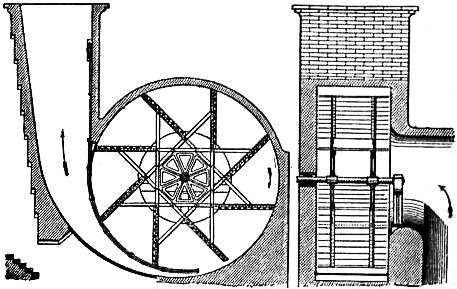
Fig. 12.—Guibal Fan.
The Waddle fan, represented in fig. 13, is an example of another class of centrifugal ventilator, in which a close casing is not used, the air exhausted being discharged from the circumference directly into the atmosphere. It consists of a hollow sheet iron drum formed by two conoidal tubes, united together by numerous guide blades, dividing it up into a series of rectangular tubes of diminishing section, attached to a horizontal axle by cast iron bosses and wrought iron arms. The tubes at their smallest part are connected to a cast iron ring, 10 ft. in diameter, but at their outer circumference they are only 2 ft. apart. The extreme diameter is 25 ft.
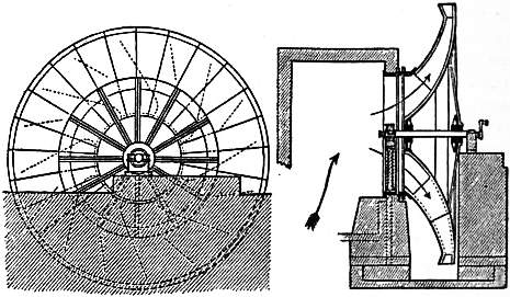
Fig. 13.—Waddle Fan.
By the adoption of more refined methods of construction, especially in the shape of the intake and discharge passages for the air and the forms of the fan blades, the efficiency of the ventilating fan has been greatly increased so that the dimensions can be much reduced and a higher rate of speed adopted. Notable examples are found in the Rateau, Ser and Capell fans, and where an electric generating station is available electric motors can be advantageously used instead of steam.
The quantity of air required for a large colliery depends upon the number of men employed, as for actual respiration from 100 to 200 cub. ft. per minute should be allowed. In fiery mines, however, a very much larger amount must be provided in order to dilute the gas to the point of safety. Distribution of air underground. Even with the best arrangements a dangerous increase in the amount of gas is not infrequent from the sudden release of stored-up masses in the coal, which, overpowering the ventilation, produce magazines of explosive material ready for ignition when brought in contact with the flame of a lamp or the blast of a shot. The management of such places, therefore, requires the most constant vigilance on the part of the workmen, especially in the examination of the working places that have been standing empty during the night, in which gas may have accumulated, to see that they are properly cleared before the new shift commences.
The actual conveyance or coursing of the air from the intake to the working faces is effected by splitting or dividing the current at different points in its course, so as to carry it as directly as possible to the places where it is required. In laying out the mine it is customary to drive the levels or roads in pairs, communication being made between them at intervals by cutting through the intermediate pillar; the air then passes along one and returns by the other. As the roads advance other pillars are driven through in the same manner, the passages first made being closed by stoppings of broken rock, or built up with brick and mortar walls, or both. When it is desired to preserve a way from one road or similar class of working to another, double doors placed at sufficient intervals apart to take in one or more trams between them when closed are used, forming a kind of lock or sluice. These are made to shut air-tight against their frames, so as to prevent the air from taking a short cut back to the upcast, while preserving free access between the different districts without following the whole round of the air-ways. The ventilation of ends is effected by means of brattices or temporary partitions of thin boards placed midway in the drift, and extending to within a few feet of the face. The air passes along one side of the brattice, courses round the free end, and returns on the other side. In many cases a light but air-proof cloth, specially made for the purpose, is used instead of wood for brattices, as being more handy and more easily removed. In large mines where the air-ways are numerous and complicated, it often happens that currents travelling in opposite directions are brought together at one point. In these cases it is necessary to cross them. The return air is usually made to pass over the intake by a curved drift carried some distance above in the solid measures, both ways being arched in brickwork, or even in some cases lined with sheet iron so as to ensure a separation not likely to be destroyed in case of an explosion (see figs. 5 and 8). The use of small auxiliary blowing ventilators underground, for carrying air into workings away from the main circuits, which was largely advocated at one time, has lost its popularity, but a useful substitute has been found in the induced draught produced by jets of compressed air or high-pressure water blowing into ejectors. With a jet of 1⁄200 in. area, a pipe discharging 12⁄3 gallon of water per minute at 165 ℔ pressure per sq. in., a circulation of 850 cub. ft. of air per minute was produced at the end of a level, or about five times that obtained from an equal volume of air at 60 ℔ pressure. The increased resistance, due to the large extension of workings from single pairs of shafts, the ventilating currents having often to travel several miles to the upcast, has led to great increase in the size and power of ventilating fans, and engines from 250 to 500 H.P. are not uncommonly used for such purposes.
The lighting of underground workings in collieries is closely connected with the subject of ventilation. In many of the smaller pits in the Midland districts of England, and generally in South Staffordshire, the coals are sufficiently Lighting. free from gas, or rather the gases are not liable to become explosive when mixed with air, to allow the use of naked lights, candles being generally used. Oil lamps are employed in many of the Scotch collieries, and are almost universally used in Belgium and other European countries. The buildings near the pit bottom, such as the stables and lamp cabin, and even the main roads for some distance, are often in large collieries lighted with gas brought from the surface, or in some cases the gas given off by the coal is used for the same purpose. Where the gases are fiery, the use of protected lights or safety lamps (q.v.) becomes a necessity.
The nature of the gases evolved by coal when freshly exposed to the atmosphere has been investigated by several chemists, more particularly by Lyon Playfair and Ernst von Meyer. The latter observer found the gases given off Composition of gas evolved by coal. by coal from the district of Newcastle and Durham to contain carbonic acid, marsh gas or light carburetted hydrogen (the fire-damp of the miner), oxygen and nitrogen. A later investigation, by J. W. Thomas, of the gases dissolved or occluded in coals from South Wales basin shows them to vary considerably with the class of coal. The results given below, which are selected from a much larger series published in the Journal of the Chemical Society, were obtained by heating samples of the different coals in vacuo for several hours at the temperature of boiling water:—
Quality. Colliery. Volume per ton in cub. ft. Composition in Volumes per cent.
Carbonic Acid. Oxygen. Marsh gas. Nitrogen.
Bituminous Cwm Clydach 19.72 5.44 1.05 63.76 29.75
” Lantwit 14.34 9.43 2.25 31.95 56.34
Steam Navigation 89.62 13.21 0.49 81.64 4.66
Anthracite Bonville’s Court 198.95 2.62 .. 93.13 4.25
In one instance about 1% of hydride of ethyl was found in the gas from a blower in a pit in the Rhondda district, which was collected in a tube and brought to the surface to be used in lighting the engine-room and pit-bank. The gases from the bituminous house coals of South Wales are comparatively free from marsh gas, as compared with those from the steam coal and anthracite pits. The latter class of coal contains the largest proportion of this dangerous gas, but holds it more tenaciously than do the steam coals, thus rendering the workings comparatively safer. It was found that, of the entire volume of occluded gas in an anthracite, only one-third could be expelled at the temperature of boiling water, and that the whole quantity, amounting to 650 cub. ft. per ton, was only to be driven out by a heat of 300° C. Steam coals being softer and more porous give off enormous volumes of gas from the working face in most of the deep pits, many of which have been the scene of disastrous explosions.
The gases evolved from the sudden outbursts or blowers in coal, which are often given off at a considerable tension, are the most dangerous enemy that the collier has to contend with. They consist almost entirely of marsh gas, with only a small quantity of carbonic acid, usually under 1%, and from 1 to 4% of nitrogen.
Fire-damp when mixed with from four to twelve times its volume of atmospheric air is explosive; but when the proportion is above or below these limits it burns quietly with a pale blue flame.
The danger arising from the presence of coal dust in the air of dry mines, with or without the addition of fire-damp, has, since it was first pointed out by Professor W. Galloway, been made the subject of special inquiries in the Coal dust. principal European countries interested in coal mining; and although certain points are still debatable, the fact is generally admitted as one calling for special precautions. The conclusions arrived at by the royal commission of 1891, which may be taken as generally representative of the views of British colliery engineers, are as follows:—
1. The danger of explosion when gas exists in very small quantities is greatly increased by the presence of coal dust.
2. A gas explosion in a fiery mine may be intensified or indefinitely propagated by the dust raised by the explosion itself.
3. Coal dust alone, without any gas, may cause a dangerous explosion if ignited by a blown-out shot; but such cases are likely to be exceptional.
4. The inflammability of coal dust varies with different coals, but none can be said to be entirely free from risk.
5. There is no probability of a dangerous explosion being produced by the ignition of coal dust by a naked light or ordinary flame.
Danger arising from coal dust is best guarded against by systematically sprinkling or watering the main roads leading from the working faces to the shaft, where the dust falling from the trams in transit is liable to accumulate. This may be done by water-carts or hose and jet, but preferably by finely divided water and compressed air distributed from a network of pipes carried through the workings. This is now generally done, and in some countries is compulsory, when the rocks are deficient in natural moisture. In one instance the quantity of water required to keep down the dust in a mine raising 850 tons of coal in a single shift was 28.8 tons, apart from that required by the jets and motors. The distributing network extended to more than 30 m. of pipes, varying from 3½ in. to 1 in. in diameter.
In all British coal-mines, when gas in dangerous quantities has appeared within three months, and in all places that are dry and dusty, blasting is prohibited, except with “permitted” explosives, whose composition and properties have been examined at the testing station at Safety explosives. the Royal Arsenal, Woolwich. A list of those sanctioned is published by the Home Office. They are mostly distinguished by special trade names, and are mainly of two classes—those containing ammonium nitrate and nitrobenzene or nitronaphthalene, and those containing nitroglycerin and nitrocellulose, which are essentially weak dynamites. The safety property attributed to them is due to the depression of the temperature of the flame or products of explosion to a point below that necessary to ignite fire-damp or coal dust in air from a blown-out shot. New explosives that are found to be satisfactory when tested are added to the list from time to time, the composition being stated in all cases.
Methods for enabling miners to penetrate into workings where the atmosphere is totally irrespirable have come into use for saving life after explosions and for repairing shafts and pit-work under water. The aerophore of A. Aerophores. Galibert was in its earlier form a bag of about 12 cub. ft. capacity containing air at a little above atmospheric pressure; it was carried on the back like a knapsack and supplied the means of respiration. The air was continually returned and circulated until it was too much contaminated with carbonic acid to be further used, a condition which limited the use of the apparatus to a very short period. A more extended application of the same principle was made in the apparatus of L. Denayrouze by which the air, contained in cylinders at a pressure of 300 to 350 ℔ per sq. in., was supplied for respiration through a reducing valve which brought it down nearly to atmospheric pressure. This apparatus was, however, very heavy and became unmanageable when more than an hour’s supply was required. The newer forms are based upon the principle, first enunciated by Professor Theodor Schwann in 1854, of carrying compressed oxygen instead of air, and returning the products of respiration through a regenerator containing absorptive media for carbonic acid and water, the purified current being returned to the mouth with an addition of fresh oxygen. The best-known apparatus of this class is that developed by G. A. Meyer at the Shamrock colliery in Westphalia, where a body of men are kept in systematic training for its use at a special rescue station. This corps rendered invaluable service at the exploring and rescue operations after the explosion at Courrières in March 1906, the most disastrous mining accident on record, when 1100 miners were killed. A somewhat similar apparatus called the “weg,” after the initials of the inventor, is due to W. E. Garforth of Wakefield. In another form of apparatus advantage is taken of the property possessed by sodium-potassium peroxide of giving off oxygen when damped; the residue of caustic soda and potash yielded by the reaction is used to absorb the carbonic acid of the expired air. Experiments have also been made with a device in which the air-supply is obtained by the evaporation of liquid air absorbed in asbestos.
Underground fires are not uncommon accidents in coal-mines. In the thick coal workings in South Staffordshire the slack left behind in the sides of work is especially liable to fire from so-called spontaneous combustion, due to the rapid oxidization that is set up when finely divided coal is brought in contact with air. The best remedy in such cases is to prevent the air from gaining access to the coal by building a wall round the burning portion, which can in this way be isolated from the remainder of the working, and the fire prevented from spreading, even if it cannot be extinguished. When the coal is fired by the blast of an explosion it is often necessary to isolate the mine completely by stopping up the mouths of the pits with earth, or in extreme cases it must be flooded with water or carbonic acid before the fire can be brought under. There have been several instances of this being done in the fiery pits in the Barnsley district, notably at the great explosion at the Oaks colliery in 1866, when 360 lives were lost.
The drawing or winding of the coal from the pit bottom to the surface is one of the most important operations Methods of winding. in coal mining, and probably the department in which mechanical appliances have been brought to the highest state of development.
The different elements making up the drawing arrangements of a colliery are—(1) the cage, (2) the shaft or pit fittings, (3) the drawing-rope, (4) the engine and (5) the surface arrangements. The cage, as its name implies, consists Cage. of one or more platforms connected by an open framework of vertical bars of wrought iron or steel, with a top bar to which the drawing-rope is attached. It is customary to have a curved sheet iron roof or bonnet when the cage is used for raising or lowering the miners, to protect them from injury by falling materials. The number of platforms or decks varies considerably; in small mines only a single one may be used, but in the larger modern pits two-, three- or even four-decked cages are used. The use of several decks is necessary in old pits of small section, where only a single tram can be carried on each. In the large shafts of the Northern and Wigan districts the cages are made about 8 ft. long and 3½ ft. broad, being sufficient to carry two large trams on one deck. These are received upon a railway made of two strips of angle iron of the proper gauge for the wheels, and are locked fast by a latch falling over their ends. At Cadeby Main with four-decked cages the capacity is eight 10-cwt. tubs or 4 tons of coal.
The guides or conductors in the pit may be constructed of wood, in which case rectangular fir beams, about 3 by 4 in., are used, attached at intervals of a few feet to buntons or cross-beams built into the lining of the pit. Two guides are required for each cage; they may be placed opposite to each other, either on the long or short sides—the latter being preferable. The cage is guided by shoes of wrought iron, a few inches long and bell-mouthed at the ends, attached to the horizontal bars of the framing, which pass loosely over the guides on three sides, but in most new pits rail guides of heavy section are used. They are applied on one side of the cage only, forming a complete vertical railway, carried by iron cross sleepers, with proper seats for the rails instead of wooden buntons; the cage is guided by curved shoes of a proper section to cover the heads of the rails. Rigid guides connected with the walling of the pit are probably the best and safest, but they have the disadvantage of being liable to distortion, in case of the pit altering its form, owing to irregular movements of the ground, or other causes. Wooden guides being of considerable size, block up a certain portion of the area of the pit, and thus offer an impediment to the ventilation, especially in upcast shafts, where the high temperature, when furnace ventilation is used, is also against their use. In the Lancashire and the Midland districts wire-rope guides have been introduced to a very considerable extent, with a view of meeting the above objections. These are simply wire-ropes, from ¾ to 1½ in. in diameter, hanging from a cross-bar connected with the pit-head framing at the surface, and attached to a similar bar at the bottom, which are kept straight by a stretching weight of from 30 cwt. to 4 tons attached to the lower bar. In some cases four guides are used—two to each of the long sides of the cage; but a more general arrangement is to have three—two on one side, and the third in an intermediate position on the opposite side. Many colliery managers, however, prefer to have only two opposite guides, as being safer. The cage is connected by tubular clips, made in two pieces and bolted together, which slide over the ropes. In addition to this it is necessary to have an extra system of fixed guides at the surface and at the bottom, where it is necessary to keep the cage steady during the operations of loading and landing, there being a much greater amount of oscillation during the passage of the cage than with fixed guides. For the same reason it is necessary to give a considerable clearance between the two lines of guides, which are kept from 15 to 18 in. apart, to prevent the possibility of the two cages striking each other in passing. With proper precautions, however, wire guides are perfectly safe for use at the highest travelling speed.
The cage is connected with the drawing-rope by short lengths of chain from the corners, known as tackling chains, gathered into a central ring to which the rope is attached. Round steel wire-ropes, about 2 in. in diameter, are Cage. now commonly used; but in very deep pits they are sometimes tapered in section to reduce the dead weight lifted. Flat ropes of steel or iron wire were and are still used to a great extent, but round ones are now generally preferred. In Belgium and the north of France flat ropes of aloe fibre (Manila hemp or plantain fibre) are in high repute, being considered preferable by many colliery managers to wire, in spite of their great weight. A rope of this class for a pit 1200 metres deep, tapered from 15.6 in. to 9 in. in breadth and from 2 in. to 11⁄8 in. in thickness, weighed 14.3 tons, and another at Anzin, intended to lift a gross load of 15 tons from 750 metres, is 22½ in. broad and 3 in. thick at the drum end, and weighs 18 tons. Tapered round ropes, although mechanically preferable, are not advantageous in practice, as the wear being greater at the cage end than on the drum it is necessary to cut off portions of the former at intervals. Ultimately also the ropes should be reversed in position, and this can only be done with a rope of uniform section.
The engines used for winding or hoisting in collieries are usually direct-acting with a pair of horizontal cylinders coupled directly to the drum shaft. Steam at high pressure exhausting into the atmosphere is still commonly used, Winding engines. but the great power required for raising heavy loads from deep pits at high speeds has brought the question of fuel economy into prominence, and more economical types of the two-cylinder tandem compound class with high initial steam pressure, superheating and condensing, have come in to some extent where the amount of work to be done is sufficient to justify their high initial cost. One of the earliest examples was erected at Llanbradack in South Wales in 1894, and they have been somewhat extensively used in Westphalia and the north of France. In a later example at the Bargold pit of the Powell Duffryn Steam Coal Company a mixed arrangement is adopted with horizontal high-pressure and vertical low-pressure cylinders. This engine draws a net load of 55 tons of coal from a depth of 625 yds. in 45 seconds, the gross weight of the four trams, cage and chains, and rope, with the coal, being 20 tons 12 cwt. The work of the winding engine, being essentially of an intermittent character, can only be done with condensation when a central condenser keeping a constant vacuum is used, and even with this the rush of steam during winding may be a cause of disturbance. This difficulty may be overcome by using Rateau’s arrangement of a low-pressure turbine between the engine and the condenser. The accumulator, which is similar in principle to the thermal storage system of Druitt Halpin, is a closed vessel completely filled with water, which condenses the excess of steam during the winding period, and becoming superheated maintains the supply to the turbine when the main engine is standing. The power so developed is generally utilized in the production of electricity, for which there is an abundant use about large collieries.
The drum, when round ropes are used, is a plain broad cylinder, with flanged rims, and cased with soft wood packing, upon which the rope is coiled; the breadth is made sufficient to take the whole length of the rope at two laps. One drum is usually fixed to the shaft, while the other is loose, with a screw link or other means of coupling, in order to be able to adjust the two ropes to exactly the same length, so that one cage may be at the surface when the other is at the bottom, without having to pay out or take up any slack rope by the engine.
For flat ropes the drum or bobbin consists of a solid disk, of the width of the rope fixed upon the shaft, with numerous parallel pairs of arms or horns, arranged radially on both sides, the space between being just sufficient to allow the rope to enter and coil regularly upon the preceding lap. This method has the advantage of equalizing the work of the engine throughout the journey, for when the load is greatest, with the full cage at the bottom and the whole length of rope out, the duty required in the first revolution of the engine is measured by the length of the smallest circumference; while the assistance derived from gravitating action of the descending cage in the same period is equal to the weight of the falling mass through a height corresponding to the length of the largest lap, and so on, the speed being increased as the weight diminishes, and vice versa. The same thing can be effected in a more perfect manner by the use of spiral or scroll drums, in which the rope is made to coil in a spiral groove upon the surface of the drum, which is formed by the frusta of two obtuse cones placed with their smaller diameters outwards. This plan, though mechanically a very good one, has certain defects, especially in the possibility of danger resulting from the rope slipping sideways, if the grooves in the bed are not perfectly true. The great size and weight of such drums are also disadvantages, as giving rather unmanageable dimensions in a very deep pit. In some cases, therefore, a combined form is adopted, the body of the drum being cylindrical, and a width equal to three or four laps conical on either side.
Counterbalance chains for the winding engines are used in the collieries of the Midland districts of England. In this method a third drum is used to receive a heavy flat link chain, shorter than the main drawing-ropes, the end of which hangs down a special or balance pit. At starting, when the full load is to be lifted, the balance chain uncoils, and continues to do so until the desired equilibrium between the working loads is attained, when it is coiled up again in the reverse direction, to be again given out on the return trip.
In Koepe’s method the drum is replaced by a disk with a grooved rim for the rope, which passes from the top of one cage over the guide pulley, round the disk, and back over the second guide to the second cage, and a tail rope, passing round a pulley at the bottom of the shaft, connects the bottoms of the cages, so that the dead weight of cage, tubs and rope is completely counterbalanced at all positions of the cages, and the work of the engine is confined to the useful weight of coal raised. Motion is communicated to the rope by frictional contact with the drum, which is covered through about one-half of the circumference. This system has been used in Nottinghamshire, and at Sneyd, in North Staffordshire. In Belgium it was tried in a pit 940 metres deep, where it has been replaced by flat hempen ropes, and is now restricted to shallower workings. In Westphalia it is applied in about thirty different pits to a maximum depth of 761 metres.
A novelty in winding arrangements is the substitution of the electromotor for the steam engine, which has been effected in a few instances. In one of the best-known examples, the Zollern colliery in Westphalia, the Koepe system is used, the winding disk being driven by two motors of 1200 H.P. each on the same shaft. Motion is obtained from a continuous-current generator driven by an alternating motor with a very heavy fly-wheel, a combination known as the Ilgner transformer, which runs continuously with a constant draught on the generating station, the extremely variable demand of the winding engine during the acceleration period being met by the energy stored in the fly-wheel, which runs at a very high speed. This arrangement works admirably as regards smoothness and safety in running, but the heavy first cost and complication stand in the way of its general adoption. Nevertheless about 60 electric winding engines were at work or under construction in May 1906.
The surface arrangements of a modern deep colliery are of considerable extent and complexity, the central feature being the head gear or pit frame carrying the guide pulleys which lead the winding ropes from the axis of the pit Surface arrangements. to the drum. This is an upright frame, usually made in wrought iron or steel strutted by diagonal thrust beams against the engine-house wall or other solid abutments, the height to the bearings of the guide pulleys being from 80 to 100 ft. or more above the ground level. This great height is necessary to obtain head-room for the cages, the landing platforms being usually placed at some considerable height above the natural surface. The pulleys, which are made as large as possible up to 20 ft. in diameter to diminish the effect of bending strains in the rope by change in direction, have channelled cast iron rims with wrought iron arms, a form combining rigidity with strength, in order to keep down their weight.
To prevent accidents from the breaking of the rope while the cage is travelling in the shaft, or from over-winding when in consequence of the engine not being stopped in time the cage may be drawn up to the head-gear pulleys (both of which are unhappily not uncommon), various forms of safety catches and disconnecting hooks have been adopted. The former contrivances consist essentially of levers or cams with toothed surfaces or gripping shoes mounted upon transverse axes attached to the sides of the cage, whose function is to take hold of the guides and support the cage in the event of its becoming detached from the rope. The opposite axes are connected with springs which are kept in compression by tension of the rope in drawing but come into action when the pull is released, the side axes then biting into wooden guides or gripping those of steel bars or ropes. The use of these contrivances is more common in collieries on the continent of Europe, where in some countries they are obligatory, than in England, where they are not generally popular owing to their uncertainty in action and the constant drag on the guides when the rope slacks.
For the prevention of accidents from over-winding, detaching hooks are used. These consist essentially of links formed of a pair of parallel plates joined by a central bolt forming a scissors joint which is connected by chain links to the cage below and the winding-rope above. The outer sides of the link are shaped with projecting lugs above. When closed by the load the width is sufficient to allow it to enter a funnel-shaped guide on a cross-bar of the frame some distance above the bank level, but on reaching the narrower portion of the guide at the top the plates are forced apart which releases the ropes and brings the lugs into contact with the top of the cross-bar which secures the cage from falling.
Three principal patterns, those of King, Ormerod and Walker, are in use, and they are generally efficient supposing the speed of the cage at arrival is not excessive. To guard against this it is now customary to use some speed-checking appliance, independent of the engine-man, which reduces or entirely cuts off the steam supply when the cage arrives at a particular point near the surface, and applies the brake if the load is travelling too quickly. Maximum speed controllers in connexion with the winding indicator, which do not allow the engine to exceed a fixed rate of speed, are also used in some cases, with recording indicators.