VOLUME VI SLICE V Clervaux to Cockade (continued 5)
Reading edition
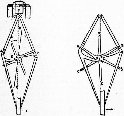
Fig. 19.—Four-legged Gravity Escapement. Fig. 20.—Double Three-legged Escapement.
Bloxam’s escapement was modified in form by Lord Grimthorpe, his chief improvement being the addition of a fly vane, which, however, had previously been used for remontoires to steady the motion. He tried various modifications of construction, but finally adopted the “four-legged” and “double-three-legged” forms as being the most satisfactory, the former for regulators and the latter for large clocks. Fig. 19 is a back view of the escapement part of an astronomical clock with the four-legged wheel; seen from the front the wheel would turn the other way. The long locking teeth are made about 2 in. long from the centre, and the lifting pins, of which four point forwards while four other intermediate ones point backwards, are at not more than 1⁄30 of the distance between the centres EC, of the scape-wheel and pallets; or rather C is the top of the pendulum spring to which the pallets Cs, Cs′ converge, though the resultant of their action is a little below C. It is not worth while to crank them as Bloxam did, in order to make them coincide exactly with the top of the pendulum, as the friction of the beat pins on the pendulum is insignificant, and even then would not be quite destroyed. The pallets are not in the same plane, but one is behind and the other in front of the wheel, with one stop pointing backwards and the other forwards to receive the teeth alternately—it does not matter which; in this figure the stop s is behind and the stop s’ forward. The pendulum is now going to the right, and just beginning to lift the right pallet and free the stop s′; then the wheel will begin to turn and lift the other pallet by one of the pins which is now lowest, and which moves through 45° across the line of centres, and therefore lifts with very little friction. It goes on till the tooth now below s reaches s and is stopped there. Meanwhile the pallet Cs’ goes on with the pendulum as far as it may go, to the end of the arc which we have called α, starting from γ; but it falls with the pendulum again, not only to γ but to -γ on the other side of 0, so that the impulse is due to the weight of each pallet alternately falling through 2γ; and the magnitude of the impulse also depends on the obliqueness of the pallet on the whole, i.e. on the distance of its centre of gravity from the vertical through C. The fly KK′ is set on with a friction spring like the common striking-part fly, and should be as long as there is room for, length being much more effective than width.
The double three-legged gravity escapement, which was first used in the Westminster clock, is shown in fig. 20. The principle of it is the same as of the four-legs; but instead of the pallets being one behind and the other in front of the wheel, with two sets of lifting pins, there are two wheels ABC, abc, with the three lifting pins and the two pallets between them like a lantern pinion. One stop B points forward and the other A backward. The two wheels have their teeth set intermediately or 60° apart, though that is not essential, and the angle of 120° may be divided between them in any other proportions, as 70° and 50°, and in that way the pallets may be still more oblique than 30° from the vertical, which, however, is found enough to prevent tripping even if the fly gets loose, which is more likely to happen from carelessness in large clocks than in astronomical ones.
Of course the fly for those escapements in large clocks, with weights heavy enough to drive the hands in all weather, must be much larger than in small ones. For average church clocks with 1¼ sec. pendulum the legs of the scape-wheels are generally made 4 in. long and the fly from 6 to 7 in. long in each vane by 1¼ or 1½ wide. For 1½ sec. pendulums the scape-wheels are generally made 4½ radius. At Westminster they are 6 in.
Lord Grimthorpe considered that these escapements act better, especially in regulators, if the pallets do not fall quite on the lifting pins, but on a banking, or stop at any convenient place, so as to leave the wheel free at the moment of starting; just as the striking of a common house clock will sometimes fail to start unless the wheel with the pins has a little run before a pin begins to lift the hammer. The best way to manage the banking is to make the beat-pins long enough to reach a little way behind the pendulum, and let the banking be a thin plate of any metal screwed adjustably to the back of the case. This plate cannot well be shown in the drawings together with the pendulum, which, it may be added, should take up one pallet just when it leaves the other.
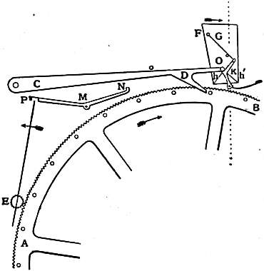
Fig. 21.—Chronometer Spring Remontoire.
In chronometer spring remontoires the pendulum, as it goes by, flips a delicate spring and releases a small weight or spring which has been wound up in readiness by the action of the scape-wheel and which by leaping on to the pendulum gives it Chronometer spring remontoire. a push. One on this principle made about the middle of the 19th century by Robert Houdin is to be seen at the Conservatoire des Arts et Métiers. It is very complicated. The following is more simple. In fig. 21 a scape-wheel AB has 30 pins and 360 teeth. It is engaged with a fly vane EP mounted on a pinion of 12 teeth. Each pin as it passes raises an impulse arm CD which is hooked upon a detent K. A pall NM then engages the fly vane and prevents the scape-wheel from moving farther. The impulse arm being now set, as the plate F attached to the lower end of the pendulum flies past from left to right a pall G knocks aside the detent K, and allows a pin O projecting from the end of the impulse arm to fall upon an inclined pallet h, which is thus urged forward. As soon as the pallet has left the pin, the impulse arm in its further fall strikes N, which disengages the pall at P and allows the scape-wheel to move on and again wind up the impulse arm CD, which is then again locked by the detent K. On the return journey of the pendulum the light pall G, which acts the part of a chronometer spring, flips over the detent. The pallet is double sided, h and h′, so that if by chance the clock runs down while the pendulum swings from left to right the impulse arm will be simply raised and not smashed. It has a flat apex, on which the pin falls before descending. The impulse given depends on the weight of the impulse arm and may be varied at pleasure. The work done in unlocking the detent is invariable, as it depends on the pressure of the fly vane at P and is independent of the clock-train. The duration of the impulse is very short—only about 1⁄10 of the arc of swing. It is given exactly at the centre of the swing, and when not under impulse the pendulum is detached.
Clock Wheels.—Since, as we have seen, any increase in the arc of a pendulum is accompanied by a change in its going rate, it is very desirable to keep the force which acts on the pendulum uniform. This in fact is the great object of the best escapements. Inasmuch as the impulse on the pendulum, derived from the work done by a falling weight or an unwinding spring, is transmitted through a train of wheels, it is desirable that that transmission should be as free from friction and as regular as possible. This involves care in the shaping of the teeth. The object to be aimed at is that as the wheel turns round the ratio of the power of the driver to that of the driven wheel (“runner” or “follower”) should never vary. That is to say, whether the back part of the tooth of the driver is acting on the tip of the tooth of the follower, or the tip of the driver is acting on the back part of the tooth of the follower, the leverage ratio shall always be uniform. For simplicity of manufacture the pinion wheels are always constructed with radial leaves, so that the surface of each tooth is a plane passing through the axis of the wheel. The semicircular rounding of the end of the tooth is merely ornamental. The question therefore is, suppose that it is desired by means of a tooth on a wheel to push a plane round an axis, what is the shape that must be given to that tooth in order that the leverage ratio may remain unaltered?
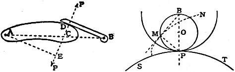
Fig. 22.—Cam and Plane. Fig. 23.
If a curved surface, known as a “cam,” press upon a plane one, both being hinged or centred upon pivots A and B respectively (fig. 22), then the line of action and reaction at D, the point where they touch, will be perpendicular to their Epicycloidal teeth. surfaces at the point of contact—that is perpendicular to BD, and the ratio of leverage will obviously be AE:BD, or AC:CB. Hence to cause the leverage ratio of the cam to the plane always to remain unaltered, the cam must be so shaped that in any position the ratio AC:CB will remain unchanged. In other words the shape of the cam must be such that, as it moves and pushes BD before it, the normal at the point of contact must always pass through the fixed point C.
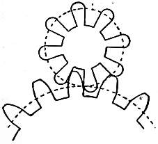
Fig. 24.
If a circle PMB roll upon another circle SPT (fig. 23) any point M on it will generate an epicycloid MN. The radius of curvature of the curve at M will always be MP, for the part at M is being produced by rotation round the point P. It follows that a line from B to M will always be tangential to the epicycloid. If the epicycloid be a cam moving as a centre round the centre R (not shown in the figure) of the circle SPT, the leverage it will exert upon a plane surface BM moving round a parallel axis at B, will always be as BP to PR, that is, a constant; whence MN is the proper shape of a tooth to act on a pinion with radial arms and centred at B. In designing a pair of wheels to transmit motion, which is to be multiplied say 6 times in the transmission (about the usual ratio for clock wheels), if we take two circles (called the “pitch circles”) touching one another with radii as 1:6, then the circumference of the smaller will roll 6 times round that of the larger. The smaller wheel will have a number of teeth, say 8 to 16, each of them being sectors of the circle (fig. 24). If there are 16 teeth, then on the surface of the driving wheel there will be 96 teeth. Each of these teeth will be shaped as the curve of an epicycloid formed by the rolling on the big circle of a circle whose diameter is the radius of the pitch circle of the pinion. Points of the teeth so formed are cut off, so as to allow of the pinion having a solid core to support it, and gaps are made into the pitch circle to admit the rounded ends of the leaves of the pinon wheel. Thus a cog-wheel is shaped out.
Clock wheels are made of hard hammered brass cut out by a wheel cutting machine. This machine consists of a vertical spindle on the top of which the wheel to be cut is fixed on a firmly resisting plate of metal of slightly smaller diameter, so as to allow the wheel to overlap. A cutter with the edges most delicately ground to the exact shape of the gap between two teeth is caused to rotate 3000 - 4000 times a minute, and brought down upon the edge of the wheel. The shavings that come off are like fine dust, but the cutter is pushed on so as to plunge right through the rim of the wheel in a direction parallel to the axis. In this way one gap is cut. The vertical spindle is now rotated one division, by means of a dividing plate, and another tooth is cut, and so the operation goes on round the wheel.
It is not desirable in clocks that the pinion wheels which are driven should have too few teeth, for this throws all the work on a pair of surfaces before the centres and is apt to produce a grinding motion. Theoretically the more leaves a pinion has the better. Pinions can be made with leaves of thin steel watch-spring. In this case quite small pinions can have 20 leaves or more. The teeth in the driving wheels then become mere notches for which great accuracy of shape is not necessary. Such wheels are easy to make and run well. Lantern pinions are also excellent and are much used in American clocks. They are easy to make in an ordinary lathe. The cog-wheels must, however, be specially shaped to fit them. They consist of a number of round pins arranged in a circle round the axis of the wheel and parallel to it. The ends are secured in flanges like the wires of a squirrel cage. The teeth of cog-wheels engage them and thus drive the wheel round. They were much used at one time but are now falling out of favour again.
It is possible to make toothed wheels that drive with perfect uniformity by using for the curve of the teeth involutes of circles. These involutes are traced out by a point on a string that is gradually unwound from a circle. They are Involute teeth. in fact epicycloids traced by a rolling circle of infinite radius, i.e. a straight line. Involute teeth have the advantage that they roll on one another instead of sliding. When badly made they put considerable strain on the axes or shafts that carry them. Hence they have not been regarded with great favour by clockmakers.
By the pitch of a wheel is meant the number of teeth to the inch of circumference or diameter of the wheel; the former is called the circumferential pitch, the latter the diametral pitch. Thus if we say that a wheel has Pitch. 40 diametral pitch we mean that it has 40 teeth to each inch of diameter. The circumferential pitch is of course got by dividing the diametral pitch by π. Wheel-cutters are made for all sizes of pitches. If it were needed to make a pair of wheels the ratio of whose motion was say 6:1 and we determined to use a diametral pitch of 30 to the inch, that is teeth about 1⁄10 in. wide at the base, and if the smaller circle were to have 20 teeth, we should need a blank of a diameter of 20⁄30 + 2⁄30 = 22⁄30 in. for the smaller wheel, and one of 120⁄30 + 2⁄30 = 122⁄30 in. for the larger wheel which would have 120 teeth to the inch and be 4.06 in diameter to the tips of the teeth. The smaller toothed wheel would be .73 of an inch in diameter over all. The pitch circles of the wheels would be 2⁄3 and 4 in. respectively. For fine wheel work, where the driver is always much larger than the driven wheel, the epicycloidal tooth appears preferable, as it is generally considered to put less side strain on the pinion wheel. But the relative merits of the two systems have never been properly tested for clock work.
Going Barrels.—A clock which is capable of going accurately must have some contrivance to keep it going while it is being wound up. In the old-fashioned house clocks, which were wound up by merely pulling one of the strings, and in which one such winding served for both the going and striking parts, this was done by what is called the endless chain of Huygens, which consists of a string or chain with the ends joined together, and passing over two pulleys on the arbors of the great wheels, with deep grooves and spikes in them, to prevent the chain from slipping. In one of the two loops or festoons which hang from the upper pulleys is a loose pulley without spikes, carrying the clock-weight, and in the other a small weight only heavy enough to keep the chain close to the upper pulleys. Now, suppose one of those pulleys to be on the arbor of the great wheel of the striking part, with a ratchet and click, and the other pulley fixed to the arbor of the great wheel of the going part; then (whenever the clock is not striking) the weight may be pulled up by pulling down that part of the string which hangs from the other side of the striking part; and yet the weight will be acting on the going part all the time. It would be just the same if the striking part and its pulley were wound up with a key, instead of the string being pulled, and also the same, if there were no striking part at all, but the second pulley were put on a blank arbor, except that in that case the weight would take twice as long to run down, supposing that the striking part generally requires the same weight × fall as the going part.
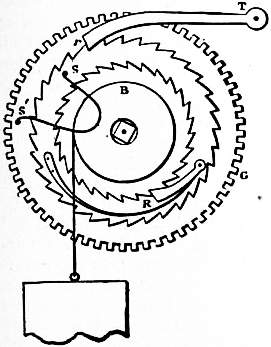
Fig. 25.—Harrison’s Going-Ratchet.
This kind of going barrel, however, is evidently not suited to the delicacy of an astronomical clock; and Harrison’s going ratchet is now universally adopted in such clocks, and also in chronometers and watches for keeping the action of the train on the escapement during the winding. Fig. 25 (in which the same letters are used as in the corresponding parts of fig. 3) shows its construction. The click of the barrel-ratchet R is set upon another larger ratchet-wheel with its teeth pointing the opposite way, and its click rT is set in the clock frame. That ratchet is connected with the great wheel by a spring ss’ pressing against the two pins s in the ratchet and s’ in the wheel. When the weight is wound up (which is equivalent to taking it off), the click Tr prevents that ratchet from turning back or to the right; and as the spring ss’ is kept by the weight in a state of tension equivalent to the weight itself it will drive the wheel to the left for a short distance, when its end s is held fast, with the same force as if that end was pulled forward by the weight; and as the great wheel has to move very little during the short time the clock is winding, the spring will keep the clock going long enough.
In the commoner kind of turret clocks a more simple apparatus is used, which goes by the name of the bolt and shutter, because it consists of a weighted lever with a broad end, which shuts up the winding-hole. When it is lifted a spring-bolt attached to the lever, or its arbor, runs into the teeth of one of the wheels, and the weight of the lever keeps the train going until the bolt has run itself out of gear. Clocks are not always driven by weights. When accuracy is not necessary, but portability is desirable, springs are used. The old form of spring became weaker as it was unwound and necessitated the use of a device called a fusee or spiral drum. This apparatus will be found described in the article Watch.
Striking Mechanism.—There are two kinds of striking work used in clocks. The older of them, the locking-plate system, which is still used in most foreign clocks, and in turret clocks in England also, will not allow the striking of any hour to be either omitted or repeated, without making the next hour strike wrong; whereas in the rack system, which is used in all English house clocks, the number of blows to be struck depends merely on the position of a wheel attached to the going part, and therefore the striking of any hour may be omitted or repeated without deranging the following ones. We shall only describe the second of these, which is the more usual in modern timepieces.
Fig. 26 is a front view of a common English house clock with the face taken off, showing the repeating or rack striking movement. Here, as in fig. 3, M is the hour-wheel, on the pipe of which the minute-hand is set, N the reversed hour-wheel, and n its pinion, driving the 12-hour wheel H, on whose socket is fixed what is called the snail Y, which belongs to the striking work exclusively. The hammer is raised by the eight pins in the rim of the second wheel in the striking train, in the manner which is obvious.
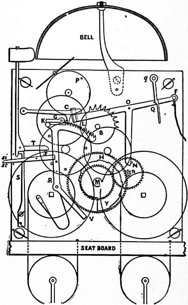
Fig. 26.—Front view of common English House Clock.
The hammer does not quite touch the bell, as it would jar in striking if it did, and prevent the full sound. The form of the hammer-shank at the arbor where the spring S acts upon it is such that the spring both drives the hammer against the bell when the tail T is raised, and also checks it just before it reaches the bell, the blow on the bell thus being given by the hammer having acquired momentum enough to go a little farther than its place of rest. Sometimes two springs are used, one for impelling the hammer, and the other for checking it. But nothing will check the chattering of a heavy hammer, except making it lean forward so as to act, partially at least, by its weight. The pinion of the striking-wheel generally has eight leaves, the same number as the pins; and as a clock strikes 78 blows in 12 hours, the great wheel will turn in that time if it has 78 teeth instead of 96, which the great wheel of the going part has for a centre pinion of eight. The striking-wheel drives the wheel above it once round for each blow, and that wheel drives a fourth (in which there is a single pin P), six, or any other integral number of turns, for one turn of its own, and that drives a fan-fly to moderate the velocity of the train by the resistance of the air, an expedient at least as old as De Vick’s clock in 1379.
The wheel N is so adjusted that, within a few minutes of the hour, the pin in it raises the lifting-piece LONF so far that that piece lifts the click C out of the teeth of the rack BKRV, which immediately falls back (helped by a spring near the bottom) as far as its tail V can go by reason of the snail Y, against which it falls; and it is so arranged that the number of teeth which pass the click is proportionate to the depth of the snail; and as there is one step in the snail for each hour, and it goes round with the hour-hand, the rack always drops just as many teeth as the number of the hour to be struck. This drop makes the noise of “giving warning.” But the clock is not yet ready to strike till the lifting piece has fallen again; for, as soon as the rack was let off, the tail of the gathering pallet G, on the prolonged arbor of the third wheel, was enabled to pass the pin K of the rack on which it was pressing before, and the striking train began to move; but before the fourth wheel had got half round, its pin P was caught by the end of the lifting-piece, which is bent back and goes through a hole in the plate, and when raised stands in the way of the pin P, so that the train cannot go on till the lifting-piece drops, which it does exactly at the hour, by the pin N then slipping past it. Then the train is free; the striking wheel begins to lift the hammer, and the gathering pallet gathers up the rack, a tooth for each blow, until it has returned to the place at which the pallet is stopped by the pin K coming under it. In this figure the lifting-piece is prolonged to F, where there is a string hung to it, as this is the proper place for such a string when it is wanted for the purpose of learning the hour in the dark, and not (as it is generally put) on the click C; for if it is put there and the string is held a little too long, the clock will strike too many; and if the string accidentally sticks in the case, it will go on striking till it is run down—neither of which things can happen when the string is put on the lifting-piece.
The snail is sometimes set on a separate stud with the apparatus called a star-wheel and jumper. On the left side of the frame we have placed a lever x, with the letters st below it, and si above. If it is pushed up to si, the other end will come against a pin in the rack, and prevent it from falling, and will thus make the clock silent; and this is much more simple than the old-fashioned “strike and silent” apparatus, which we shall therefore not describe, especially as it is seldom used now.
If the clock is required to strike quarters, a third “part” or train of wheels is added on the right hand of the going part; and its general construction is the same as the hour-striking part; only there are two more bells, and two hammers so placed that one is raised a little after the other. If there are more quarter-bells than two, the hammers are generally raised by a chime-barrel, which is merely a cylinder set on the arbor of the striking-wheel (in that case generally the third in the train), with short pins stuck into it in the proper places to raise the hammers in the order required for the tune of the chimes. The quarters are usually made to let off the hour, and this connexion may be made in two ways. If the chimes are different in tune for each quarter, and not merely the same tune repeated two, three and four times, the repetition movement must not be used for them, as it would throw the tunes into confusion, but the old locking-plate movement, as in turret clocks; and therefore, if we conceive the hour lifting-piece connected with the quarter locking-plate, as it is with the wheel N, in fig. 26, it is evident that the pin will discharge the hour striking part as the fourth quarter finishes.
But where the repetition movement is required for the quarters, the matter is not quite so simple. The principle of it may shortly be described thus. The quarters themselves have a rack and snail, &c., just like the hours, except that the snail is fixed on one of the hour-wheels M or N, instead of on the twelve-hour wheel, and has only four steps in it. Now suppose the quarter-rack to be so placed that when it falls for the fourth quarter (its greatest drop), it falls against the hour lifting-piece somewhere between O and N, so as to raise it and the click C. Then the pin Q will be caught by the click Qq, and so the lifting-piece will remain up until all the teeth of the quarter-rack are gathered up; and as that is done, it may be made to disengage the click Qq, and so complete the letting off the hour striking part. This click Qq has no existence except where there are quarters.
The method in which an alarum is struck may be understood by reference to either of the recoil escapements (figs. 1 and 7). If a short hammer instead of a long pendulum be attached to the axis of the pallets, and the wheel be driven with sufficient force, it will evidently swing the hammer rapidly backwards and forwards; and the position and length of the hammer-head may be so adjusted as to strike a bell inside, first on one side and then on the other. As to the mode of letting off the alarum at the time required: if it was always to be let off at the same time all that would be necessary would be to set a pin in the twelve-hour wheel at the proper place to raise the lifting-piece which lets off the alarum at that time. But as the time must be capable of alteration, this discharging pin must be set in another wheel (without teeth), which rides with a friction-spring on the socket of the twelve-hour wheel, with a small movable dial attached to it, having figures so arranged with reference to the pin that whatever figure is made to come to a small pointer set as a tail to the hour hand, the alarum shall be let off at that hour.
The watchman’s or tell-tale clock, used when it is desired to make sure of a watchman being on the spot and awake all the night, is a clock with a set of spikes, generally 48 or 96, sticking out all round the dial, and a handle somewhere in the case, by pulling which one of the spikes which is opposite to it, or to some lever connected with it is pressed in. This wheel of spikes is carried round with the hour-hand, which in these clocks is generally a twenty-four hour one. It is evident that every spike which is seen still sticking out in the morning indicates that at the particular time to which that spike belongs the watchman was not there to push it in—or at any rate, that he did not. At some other part of their circuit, the inner ends of the pins are carried over a roller or an inclined plane which pushes them out again ready for business the next night. The time at which workmen arrive at their work may be recorded by providing each of them with a numbered key with which he stamps his number on a moving tape, on which also the time is marked by a clock.
Church and Turret Clocks.—Seeing that a clock—at least the going part of it—is a machine in which the only work to be done is the overcoming of its own friction and the resistance of the air, it is evident that when the friction and resistance are much increased it may become necessary to resort to expedients for neutralizing their effects, which are not required in a smaller machine with less friction. In a turret clock the friction is enormously increased by the great weight of all the parts; and the resistance of the wind, and sometimes snow, to the motion of the hands, further aggravates the difficulty of maintaining a constant force on the pendulum; and besides that, there is the exposure of the clock to the dirt and dust which are always found in towers, and of the oil to a temperature which nearly or quite freezes it all through the usual cold of winter. This last circumstance alone will generally make the arc of the pendulum at least half a degree more in summer than in winter; and inasmuch as the time is materially affected by the force which arrives at the pendulum, as well as the friction on the pallets when it does arrive there, it is evidently impossible for any turret clock of the ordinary construction, especially with large dials, to keep any constant rate through the various changes of temperature, weather and dirt to which it is exposed. Hence special precautions, such as the use of remontoires and gravity escapements, have to be observed in the design of large clocks that have any pretensions to accuracy, in order to ensure that the arc of the pendulum is not affected by external circumstances, such as wind-pressure on the hands or dirt in the wheel-train. But such have been the improvements effected in electric clocks, that rather than go to the trouble and expense required by such precautions, it appears far preferable to keep an accurate time-piece in some sheltered position and use it with a source of electricity to drive the hands of the large dial.
Electrical Clocks.—One of the first attempts to apply electricity to clocks was made by Alexander Bain in 1840-1850. About the same time Sir C. Wheatstone, R. L. Jones, C. Shepherd, Paul Garnier and Louis Bréguet invented various forms of electrical time-keepers. It is not proposed here to go into the history of these abortive attempts. Those who desire to follow them may consult Bain, An Account of Some Applications of the Electric Fluid to the Useful Arts (1843) and Short History of Electric Clocks (1852); Sir Charles Wheatstone, Trade Circular of the British Telegraph Manufactory; C. Shepherd, On the Application of Electro-magnetism as a Motor for Clocks (1851), and a list of references in the Appendix to Tobler’s Die electrischen Uhren (Leipzig, 1883), and a list of books given by F. Hope Jones, Proc. Inst. Elec. Eng., 1900, vol. 29. The history of electrical clocks is a long and complicated matter, for there are some 600 or 700 patents for these clocks in Europe and America, some containing the germs of valuable ideas but most pure rubbish. All that can be done is to select one or two prominent types of each class and give a brief description of their general construction.
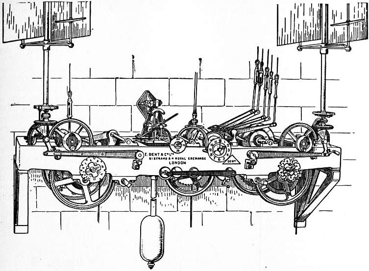
Fig. 27.—Turret Clock for Hidalgo, Mexico, driving four 8 ft. dials.
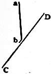
Fig. 28.
It is in the apparently simple matter of making and keeping the electrical contact that most of the systems of electrical time-keeping have failed, for want of attention to the essential conditions of the problem. In practice every metal is covered with a thin film of non-conducting oxide over which is another film of moisture, oil, dirt or air. Hence what is wanted is a good vigorous push of a blunted point or edge preferably obliquely upon a more or less yielding surface so as to get a rubbing action. Thus if the stiff spring a b (fig. 28) were stabbed down on the oblique surface C D a good contact would invariably result, provided that the metals employed were gold, platinum or some not easily oxidizable metal. Or again, if a mercury surface be simply touched with a pin, the slight sparking that is produced on making the current will soon form a little pile of dirty oxide at the point of entry, and the contact will frequently fail. If it be necessary to have a mercury contact, the pin must be well driven in below the surface of the mercury or else swept through it as an oar is swept through the water. Another form of electrical contact that acts well is a knife edge brought into contact with a series of fine elastic strips of metal laid parallel to one another like the fingers of a hand. The best metal for contacts, if they are to bear hard usage, is either silver or gold or a mixture of 40% iridium with 60% of platinum. A pressure of some 15 grammes, at least, is needful to secure a good contact.
As to the source of current for driving electrical clocks, if Leclanché cells be used they should preferably be kept in the open air under cover so as not to dry up. If direct electric current is available from electric light mains or the accumulators used for lighting a private house, so much the better. Of course the pressure of 50 or 100 volts used for lighting would be far too great for clock-driving, where only the pressure of a few volts is required. But it is easy by the insertion of suitable resistances, as for instance one or more incandescent lamps, to weaken down the pressure of the lighting system and make it available for electric clocks, bells or other similar purposes.
Electricity is applied to clocks in three main ways:—(1) in actuating timepieces which measure their own time and must therefore be provided with pendulums or balance wheels; (2) in reproducing on one or more dials the movements of the hands of a master clock, by the aid of electric impulses sent at regular intervals, say of a minute or a half-minute; and (3) in synchronizing ordinary clocks by occasional impulses sent from some accurate regulator at a distance.
Electrically driven timepieces may be divided under two heads:—(a) those in which the electric current drives either the pendulum or some lever which operates upon it, which lever or pendulum in turn drives the clock hands; and (b) those timepieces which are driven by a weight or spring which is periodically wound up by electricity—in fact electrical remontoires.
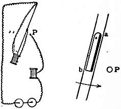
Fig. 29.—Electrical Clock (faulty design).
The simplest clock of the first character that could be imagined would be constructed by fastening an electromagnet with a soft iron core to the bottom of a pendulum, and causing it to be attracted as the pendulum swings by another electromagnet fixed vertically under it (fig. 29). As the pendulum approached the vertical and was say half an inch from its lowest point, the current would be switched on, and switched off as soon as the pendulum got to its lowest point. A very small attraction with this arrangement, probably about a grain weight, acting through the ½ in. would drive a heavy pendulum. A switch would have to be worked in connexion with the pendulum. A strip of ebonite with a small face of metal on the end of one side, such as a b (fig. 29) might be pivoted at one end on the pendulum with a weak spring to keep it where free along the rod. As the pendulum swung by this would be swept on its journey from left to right against a fixed pin P. This would complete the electric circuit down through the pendulum rod, round the coil on the bottom of the pendulum, through the switch into the pin P, thence through the fixed electromagnet, and so back to the battery. On the return journey no contact would be made because only the ebonite face of the switch would touch P. The pendulum would thus receive an impulse every other vibration. We have described this switch, not to advocate it, but to warn against its use. For the contact would be quite insufficient. In order that the switch might not unduly retard the pendulum it must be light, but this would make the pressure on P too light to be trustworthy. Moreover, the strength of the impulse would vary with the strength of the battery, and hence the arc would be repeatedly uneven.

Fig. 30.—Hipp Electrical Clock (Peyer, Favarger et Cie.).
In contrast with this, let us consider a clock that is now giving excellent results at the Observatory of Neuchatel in Switzerland on Hipp’s system (La Pendule électrique de précision, Neuchatel, 1884 and 1891). The pendulum (fig. 30) consists of two rods of steel joined by four bridges, one just below the suspension spring, the next about 12 in. lower, the next about half way down, and the last supporting a glass vessel of mercury which forms the bob. On the third of them is placed an iron armature, which works between the poles of an electromagnet fixed to the case, and by which the pendulum is actuated. The circuit is closed and broken by a flipper, which is swayed to and fro by a block fixed to the pendulum at the second bridge. As long as the flipper is merely swayed, no contact takes place, but when the arc of vibration of the pendulum is diminished the flipper does not clear the block but is caught by a nick in it, and forced downwards. In this way the circuit is closed. Fig. 31 is a diagram of the apparatus. When the block g attached to the pendulum catches and presses down the flipper s, the lever l l is rocked over, so that a contact is made at k, and the current which enters the lever l through the knife edge m, runs through the second lever n n, down through the knife edge o, to the battery, and through the electromagnet b which causes the armature a to be attracted. As the block g goes on and releases s, the lever l again falls upon the rest p, the lever n follows it a part of the way till it is stopped by the contact q; this shortcircuits the electromagnet and prevents to a large extent the formation of an induced current. It is claimed that sparking is by this method almost entirely avoided. It is only when s is caught in the notch of the block g that s is pressed down, so that the electric attraction only takes place every few vibrations. This ingenious arrangement makes the working of the clock nearly independent of the strength of the battery, for if the battery is strong the impulses are fewer and the average arc remains the same. The clock is enclosed in an airtight glass case so as to avoid barometric error. It was tested in 1905 at the Neuchâtel observatory. In winter in a room of a mean temperature of 35° F. it was ¼ sec. too slow, in summer when the temperature was 70°, it was ½ sec. too fast. In the succeeding winter it became .53 sec. too slow again, thus gaining a little in summer and losing in winter. Its average variation from its daily rate was, however, only .033 sec.
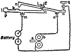
Fig. 31.—Contact Arrangement of Hipp Clock.
In another system originated by G. Froment, a small weight is raised by electricity and allowed to fall upon an arm sticking out at right angles to the pendulum in the plane of its motion, so as to urge it onwards. The weight is only allowed to rest on the arm during the downward swing of the pendulum. The method is not theoretically good, as the impulse is given at the end of the vibration of the pendulum instead of at its middle position.
In the clock invented by C. Féry (chef des travaux pratiques at the École de Physique et Chimie, Paris), an electric impulse is given at every vibration, not by a battery but by means of the uniform movement of an armature which is alternately pulled away from and pushed towards a permanent horseshoe magnet. Currents are thus induced in a bobbin of fine wire placed between the poles of the horseshoe magnet. The movements of the armature are produced by another horseshoe magnet actuated by the primary current from a battery which is turned on and off by the swinging of the pendulum. The energy of the induced current that drives the clock depends solely on the total movement of the armature, and is independent of whether that movement be executed slowly or rapidly, and therefore of the strength of the battery.
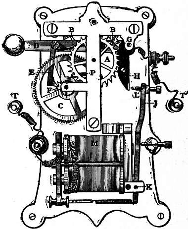
Fig. 32.—Hope Jones Electrical Remontoire.
Electrical remontoires possess great advantages if they can be made to operate with certainty. For they can be made to wind up a scape-wheel just as is done in the case of the arrangement shown in fig. 16 so as to constitute a spring remontoire, or better still they can be made to raise a weight as in the case of the gravity train remontoire (fig. 15) but without the complications of wheel-work shown in that contrivance. Of this type one of the best known is that of H. Chesters Pond. A mainspring fixed on the arbor of the hour wheel is wound up every hour by means of another toothed wheel riding loose on the same arbor and driven by a small dynamo, to which the other end of the mainspring is attached. As soon as the hour wheel has made one revolution (driven round by the spring), a contact switch is closed whereupon the dynamo winds up the spring again exactly as the train and fly wind up the spring in fig. 15. These clocks require a good deal of power, and not being always trustworthy seem to have gone out of use. A contrivance of this kind now in use is that patented by F. Hope Jones and G.B. Bowell, and is represented in fig. 32. A pendulum is driven by the scape-wheel A, and pallets B B in the usual way. The scape-wheel is driven by another wheel C which, in turn, is driven by the weighted lever D supported by click E engaging the ratchet wheel F. This lever is centred at G and has an extension H at right angles to it. J is an armature of soft iron pivoted at K and worked by the electromagnet M. D gradually falls in the act of driving the clock by turning the wheels C and A until the contact plate on the arm H meets with the contact screw L at the end of the armature J, thus completing the electrical circuit from terminal T to terminal T′ through the electromagnet M, and through any number of step-by-step dial movements which may be included in the same series circuit. The armature is then drawn towards the magnet with rapid acceleration, carrying the lever D with it. The armature is suddenly arrested by the poles of the magnet, but the momentum of the lever D carries it farther, and the click E engages another tooth of the ratchet F. A quick break of the circuit is thus secured, and the contact at L is a good one, first because the whole of the energy required to keep the clock going, or in other words the energy required to raise the lever D is mechanically transmitted through its surfaces at each operation, and secondly, owing to the arrangement of the fulcrums at G and K which secure a rubbing contact. The duration of the contact is just that necessary to accomplish the work which has to be done, and it is remarkable that when used to operate large circuits of electrically propelled dials the duration accommodates itself to their exact requirements and the varying conditions of battery and self-induction. The ratchet wheel F is usually mounted loosely upon its arbor and is connected to the wheel C by means of a spiral spring, which in conjunction with the back-stop click P maintains the turning force on the wheelwork at the instant when the lever D is being raised.
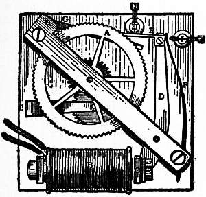
Fig. 33.—Hope Jones’s Dial-driving Device.
Electrically driven dials usually consist of a ratchet wheel driven by an electrically moved pall. Care has to be taken that the pushes of the pall do not cause the ratchet wheel to be impelled too far. The anchor escapement of a common grandfather’s clock can be made to drive the works by means of an electromagnet, the pendulum being removed. With a common anchor escapement the scape-wheel can be driven round by wagging the anchor to and fro. All then that is necessary is to fix a piece of iron on the anchor so that its weight pulls the anchor over one way, while an electromagnet pulls the iron the other. Impulses sent through the electromagnet will then drive the clock. If the clock is wound up in the ordinary way the motion will be so much helped that the electric current has very little to do, and thus may be very feeble. Fig. 33 shows the dial-driving device of Hope Jones’s clock. Each time that a current is sent by the master-clock, the electromagnet B attracts the pivoted armature C, and when the current ceases the lever D with the projecting arm E is driven back to its old position by the spring F, thus driving the wheel A forward one division. G is a back-stop click, and H, I, fixed stops.
It seems doubtful whether in large towns a number of dials could be electrically driven from a distance because of the large amount of power that would have to be transmitted. But for large buildings, such as hotels, they are excellent. One master-clock in the cellar will drive a hundred or so placed over the building. The master-clock may itself be driven by electricity, but it will require the services from time to time of some one to correct the time. Even this labour may be avoided if the master-clock is synchronized, and as synchronization requires but a small expenditure of force, it can be done over large areas. Hence the future of the clock seems to be a series of master-clocks, electrically driven, and synchronized one with another, in various parts of a city, from each of which a number of dials in the vicinity are driven. Electrical synchronization was worked out by Louis Bréguet and others, and a successful system was perfected in England by J.A. Lund. The leading principle of the best systems is at each hour to cause a pair of fingers or some equivalent device to close upon the minute hand and put it exactly to the hour. Other systems are designed to retard or to accelerate the pendulum, but the former appears the more practical method. There is probably a future before synchronization which will enable the services of a clockmaker to be largely dispensed with and relegate his work merely to keeping the instruments in repair.
Miscellaneous Clocks.—Some small clocks are made to go for a year. They have a heavy balance wheel of brass weighing about 2 1b and about 2½ in. in diameter, suspended from a point above its centre by a fine watch spring about 4 in. long. The crutch engages with the upper part of the spring, and as the balance wheel swings the pallets are actuated. The whole clock is but a large watch with a suspended balance wheel, oscillating once in about 8 seconds. Unless the suspension spring be compensated for temperature, such clocks gain very much in winter.
An ingenious method of driving a clock by water has been proposed. As the pendulum oscillates to one side, an arm on it rises and at last lightly touches a drop of water hanging from a very fine nozzle; this drop is taken off and carried away by the arm, to be subsequently removed by adhesion to an escape funnel placed below the arm. Hence at each double vibration of the pendulum part of the work done by a drop of water falling through a short distance is communicated to the pendulum, which is thus kept in motion as long as the water lasts. At this rate a gallon of water ought to drive the clock for 40 hours. Care of course must be taken to keep the water in the reservoir at a constant level, so that the drops formed shall be uniform.
If it were worth while, no doubt the oscillations of a pendulum working in a vacuum could be maintained by the communication and discharge at each oscillation of a slight charge of electricity; or again, heat might at each oscillation be communicated to a thermo-electric junction, and the resulting current used to drive the pendulum.
The expansions and contractions of metal rods under the influence of the changes of temperature which take place in the course of each night and day have also been employed to keep a clock wound up, and if there were any need for it no doubt a small windmill rotating at the top of a tower would easily keep a turret clock fully wound, by a simple arrangement which would gear the going barrel of the clock to the wind vane motion, whenever the weight had fallen too low, and release it when the winding up was completed. Even a smoke jack would do the same office for a kitchen clock.
The methods of driving astronomical telescopes by means of clockwork will be found in the article Telescope. Measurements of small intervals of time are performed by means of chronographs which in principle depend on the use of isochronous vibrating tuning-forks in place of pendulums. In practice it is needful in most cases that an observer should intervene in time measurements, although perhaps by means of a revolving photographic film a transit of the sun might be timed with extraordinary accuracy. But if the transit of a star across a wire is to be observed, there is no mode at present in use of doing so except by the use of the human eye, brain and hand. Hence in all such observations there is an element of personal error. Unfortunately we cannot apply a microscope to time as we can to space and make the cycle of events that takes place in a second last say for five minutes so as to time them truly. By personal observations the divisions of a second cannot in general be made more accurately than to 1⁄10 or 1⁄15 of a second. The most rapid music player does not strike a note more than 10 or 12 times in a second. It is only in case of recurring phenomena that we can make personal observations more accurate than this by taking the mean of a large number of observations, and allowing for personal error. For the purpose of determining longitude at sea accuracy to 1⁄30 of a second of time would find the place to about 20 yards. It seems to follow that the extent to which astronomical clocks can be made accurate, viz. to 1⁄30 of a second average variation from their mean daily rate, or one two-and-a-half millionth of 24 hours, is a degree of accuracy sufficient for present purposes, and it seems rather doubtful whether mechanical science will in the case of clocks be likely to reach a much higher figure.
In the 17th century it was a favourite device to make a clock show sidereal time as well as mean solar time. The length of the sidereal day is to the mean solar day as .99727 to 1, and various attempts have been made by trains of wheels to obtain this relation—but all are somewhat complicated.
Magical clocks are of several kinds. One that was in vogue about 1880 had a bronze figure on the top with outstretched arm holding in its hand the upper part of the spring of a pendulum, about 10 in. long. The pendulum had apparently no escapement and the puzzle was how it was maintained in motion. It was impossible to detect the mystery by the aid of the eye alone; the truth, however, was that the whole figure swung to and fro at each oscillation of the pendulum, to an amount of 1⁄400 of an inch on the outside rim of the base. A movement of 1⁄400 of an inch per half second of time is imperceptible; it would be equivalent to perception of motion of the minute hand of a clock about 6 in. in diameter, which is almost impossible. The connexion of the figure to the anchor of the escapement was very complicated, but clocks of the kind kept fair time. A straw, poised near the end on a needle and with the short end united by a thread to the bronze figure, makes the motion apparent at once and discloses the trick. Another magical clock consists of two disks of thin sheet glass mounted one close behind the other, one carrying the minute hand and the other the hour hand. The disks rest on rollers which rotate and turn them round. The front and back of the movable disks are covered by other disks of glass surrounded by a frame, so that the whole looks simply like a single sheet of glass mounted in a frame, in the centre of which the hands rotate, without any visible connexion with the works of the clock.
Clocks have been made with a sort of balance wheel consisting of a thread with a ball at the end which winds backwards and forwards spirally round a rod. In others a swing or see-saw is attached to the pendulum, or a ship under canvas is made to oscillate in a heavy sea. In others the time is measured by the fall of a ball down an inclined plane, the time of fall being given by the formula t = √(2s/g sin a), where s is the length of the incline and a the inclination. But friction so modifies the result as to render experiment the only mode of adjusting such a clock. Sometimes a clock is made to serve as its own weight, as for instance when a clock shaped like a monkey is allowed to slide down a rope wound round the going barrel. Or the clock is made of a cylindrical shape outside and provided with a weighted arm instead of a going barrel; on being put upon an incline, it rolls down, and the fall supplies the motive power.
Clocks are frequently provided with chimes moved exactly like musical boxes, except that the pins in the barrel, instead of flipping musical combs, raise hammers which fall upon bells. The driving barrel is let off at suitable intervals. The cuckoo clock is a pretty piece of mechanism. By the push of a wire given to the body of the bird, it is bent forward, the wings and tail are raised and the beak opened. At the same time two weighted bellows measuring about 1 × 2 in. are raised and successively let drop. These are attached to small wooden organ pipes, one tuned a fifth above the other, which produce the notes. Phonographs are also attached to clocks, by which the hours are called instead of rung.
Clocks are also constructed with conical pendulums. It is a property of the conical pendulum that if swung round, the time of one complete revolution is the same as that of the double vibration of a pendulum equal in length to the vertical distance of the bob of the conical pendulum below its point of support. It follows that if the driving force of such a pendulum can be kept constant (as it easily can by an electric contact which is made at every revolution during which it falls below a certain point) the clock will keep time; or friction can be introduced so as to reduce the speed whenever the pendulum flies round too fast and hence the bob rises. Or again by suitable arrangements the bob may be made to move in certain curves so as to be isochronous. Plans of this kind are employed rather to drive telescopes, phonographs and other machines requiring uniform and steady movement.
Comical and performing clocks were very popular in the 15th and 16th centuries. One at Basel in Switzerland was arranged so as gradually to protrude a long tongue as the pendulum vibrated. It is still to be seen there in the museum. The famous clock at Strassburg, originally constructed in 1574, remade in 1842, displays a whole series of scenes, including processions of the apostles and other persons, and a cock that crows. A fine clock at Venice has two rather stiff bronze giants that strike the hours.
Clocks with complicated movements representing the positions of the heavenly bodies and the days of the week and month, allowance being made for leap year, were once the delight of the curious. Repeating clocks, which sounded the hours when a string was pulled, were once popular. The string simply raised the lifting piece and let the clock strike as the hands would do when they came to the hour. This was of use in the old days when the only mode of striking a light at night was with a flint and steel, but lucifer matches and the electric light have rendered these clocks obsolete.
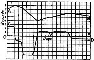
Fig. 34.—Curve of Variation of daily rate.
Testing Clocks.—The average amount by which a clock gains or loses is called its mean or average daily rate. A large daily rate of error is no proof that a clock is a bad one, for it might be completely removed by pendulum adjustment. What is required is that the daily rate shall be uniform, that is, that the clock shall not be gaining (or losing) more on one day than on another, or at one period of the same day than at another. In fig. 34 A B is a curve in which the abscissae represent intervals of time, the ordinates the number of seconds at any time by which the clock is wrong. The curve C D is one in which the ordinates are proportional to the tangents of the angles of inclination of the curve A B to the axis of x, that is dy/dx. Whenever the line A B is horizontal, C D cuts the axis of x. In a clock having no variation in its daily rate the curve A B would become a straight line, though it might be inclined to the axis of x, and C D, also a straight line, would be parallel to the axis of x, though it might not coincide with it. In a clock set to exact time and having no variations of daily rate, both the curves would be straight lines and would coincide with the axis of x. The curve C D, known as the curve of variation of daily rate, will generally be found to follow changes of day and night, and of temperature, and the fluctuations of the barometer and hygrometer; it is the curve which reveals the true character of the clock. Hence in testing a clock two things have to be determined: first, the daily rate of error, and second, the average variations from that daily rate, in other words the irregularities of going. To test a clock well six months’ or a year’s trial is needed, and it is desirable to have it subjected to considerable changes of temperature.
The bibliography of horology is very extensive. Among modern works Lord Grimthorpe’s Rudimentary Treatise on Clocks, Watches and Bells (8th edition, London, 1903) is perhaps the most convenient. Many references to older literature will be found in Thomas Reid’s Treatise on Clock and Watchmaking (1849).
(G.; H. H. C.)
Decorative Aspects.—In art the clock occupies a position of considerable distinction, and antique examples are prized and collected as much for the decorative qualities of their cases as for the excellence of their time-keeping. French and English cabinet-makers have especially excelled, although in entirely different ways, in the making of clock cases. The one aimed at comely utility, often made actually beautiful by fit proportion and the employment of finely grained woods; the other sought a bold and dazzling splendour in which ornament overlay material. It was not in either country until the latter part of the 17th century that the cabinet-maker’s opportunity came. The bracket or chamber clock gave comparatively little scope to the worker in wood—in its earlier period, indeed, it was almost invariably encased in brass or other metal; and it was not until the introduction of the long pendulum swinging in a small space that it became customary to encase clocks in decorative woodwork. The long or “grandfather” clock dates from about the fourth quarter of the 17th century—what is, perhaps, the earliest surviving English dated specimen is inscribed with the date 1681. Originally it was a development of the dome-shaped bracket clock, and in the older examples the characteristic dome or canopy is preserved. The first time-keepers of this type had oaken cases—indeed oak was never entirely abandoned; but when walnut began to come into favour a few years later that beautifully marked wood was almost invariably used for the choicest and most costly specimens. Thus in 1698 the dean and chapter of St Paul’s cathedral paid the then very substantial price of £14 for an inlaid walnut long-cased eight-day clock to stand in one of the vestries. The rapidity with which the new style came into use is suggested by the fact that while very few long clocks can be certainly dated before 1690, between that year and the end of the century there are many examples. Throughout the 18th century they were made in myriads all over England, and since they were a prized possession it is not surprising that innumerable examples have survived. Vary as they may in height and girth, in wood and dial, they are all essentially alike. In their earlier years their faces were usually of brass engraved with cherubs’ heads or conventional designs, but eventually the less rich white face grew common. There are two varieties—the eight-day and the thirty-hour. The latter is but little esteemed, notwithstanding that it is often as decorative as the more expensive clock. The favourite walnut case of the late 17th and early 18th century gave place in the course of a generation to mahogany, which retained its primacy until the introduction of cheaper clocks brought about the supersession of the long-cased variety. Many of these cases were made in lacquer when that material was in vogue; satinwood and other costly foreign timbers were also used for bandings and inlay. The most elegant of the “grandfather” cases are, however, the narrow-waisted forms of the William and Mary period in walnut inlay, the head framed in twisted pilasters. Long clocks of the old type are still made in small numbers and at high prices; they usually contain chimes. During the later period of their popularity the heads of long clocks were often filled in with painted disks representing the moon, by which its course could be followed. Such conceits as ships moving on waves or time with wings were also in favour. The northern parts of France likewise produced tall clocks, usually in oaken cases; those with Louis Quinze shaped panels are often very decorative. French love of applied ornament was, however, generally inimical to the rather uncompromising squareness of the English case, and the great Louis Quinze and Louis Seize cabinetmakers made some magnificent and monumental clocks, many of which were “long” only as regards the case, the pendulum being comparatively short, while sometimes the case acted merely as a pedestal for a bracket-clock fixed on the top. These pieces were usually mounted very elaborately in gilt bronze, cast and chased, and French bracket and chamber clocks were usually of gilded metal or marble, or a combination of the two; this essentially late 18th-century type still persists. English bracket clocks contemporary with them were most frequently of simple square or arched form in mahogany. The “grandfather” case was also made in the Low Countries, of generous height, very swelling and bulbous.
See F. J. Britten, Old Clocks and Watches and their Makers (2nd edition, London, 1904); Mathieu Planchon, L’Horloge, son histoire retrospective, pittoresque et artistique (Paris, 1899).
(J. P. -B.)
CLODIA, VIA, an ancient high-road of Italy. Its course, for the first 11 m., was the same as that of the Via Cassia; it then diverged to the N.N.W. and ran on the W. side of the Lacus Sabatinus, past Forum Clodii and Blera. At Forum Cassii it may have rejoined the Via Cassia, and it seems to have taken the same line as the latter as far as Florentia (Florence). But beyond Florentia, between Luca (Lucca) and Luna, we find another Forum Clodii, and the Antonine Itinerary gives the route from Luca to Rome as being by the Via Clodia—wrongly as regards the portion from Florentia southwards, but perhaps rightly as regards that from Luca to Florentia. In that case the Clodius whose name the road bears, possibly C. Clodius Vestalis (c. 43 B.C.), was responsible for the construction of the first portion and of that from Florentia to Luca (and Luna), and the founder of the two Fora Clodii. The name seems, in imperial times, to have to some extent driven out that of the Cassia, and both roads were administered, with other minor roads, by the same curator.
See Ch. Hülsen in Pauly-Wissowa, Realencyclopädie, iv. 63; cf. Cassia, Via.
(T. As.)
CLODIUS,1 PUBLIUS (c. 93-52 B.C.), surnamed Pulcher, Roman politician. He took part in the third Mithradatic war under his brother-in-law Lucius Licinius Lucullus, but considering himself treated with insufficient respect, he stirred up a revolt; another brother-in-law, Q. Marcius Rex, governor of Cilicia, gave him the command of his fleet, but he was captured by pirates. On his release he repaired to Syria, where he nearly lost his life during a mutiny instigated by himself. Returning to Rome in 65, he prosecuted Catiline for extortion, but was bribed by him to procure acquittal. There seems no reason to believe that Clodius was implicated in the Catilinarian conspiracy; indeed, according to Plutarch (Cicero, 29), he rendered Cicero every assistance and acted as one of his body-guard. The affair of the mysteries of the Bona Dea, however, caused a breach between Clodius and Cicero in December 62. Clodius, dressed as a woman (men were not admitted to the mysteries), entered the house of Caesar, where the mysteries were being celebrated, in order to carry on an intrigue with Caesar’s wife. He was detected and brought to trial, but escaped condemnation by bribing the jury. Cicero’s violent attacks on this occasion inspired Clodius with the desire for revenge. On his return from Sicily (where he had been quaestor in 61) he renounced his patrician rank, and, having with the connivance of Caesar been adopted by a certain P. Fonteius, was elected tribune of the people (10th of December 59). His first act was to bring forward certain laws calculated to secure him the popular favour. Corn, instead of being sold at a low rate, was to be distributed gratuitously once a month; the right of taking the omens on a fixed day and (if they were declared unfavourable) of preventing the assembly of the comitia, possessed by every magistrate by the terms of the Lex Aelia Fufia, was abolished; the old clubs or gilds of workmen were re-established; the censors were forbidden to exclude any citizen from the senate or inflict any punishment upon him unless he had been publicly accused and condemned. He then contrived to get rid of Cicero (q.v.) and the younger Cato (q.v.), who was sent to Cyprus as praetor to take possession of the island and the royal treasures. Cicero’s property was confiscated by order of Clodius, his house on the Palatine burned down, and its site put up to auction. It was purchased by Clodius himself, who, not wishing to appear in the matter, put up some one to bid for him. After the departure of Caesar for Gaul, Clodius became practically master of Rome with the aid of armed ruffians and a system of secret societies. In 57 one of the tribunes proposed the recall of Cicero, and Clodius resorted to force to prevent the passing of the decree, but was foiled by Titus Annius Milo (q.v.), who brought up an armed band sufficiently strong to hold him in check. Clodius subsequently attacked the workmen who were rebuilding Cicero’s house at the public cost, assaulted Cicero himself in the street, and set fire to the house of Q. Cicero. In 56, when curule aedile, he impeached Milo for public violence (de vi), when defending his house against the attacks of Clodius, and also charged him with keeping armed bands in his service. Judicial proceedings were hindered by outbreaks of disturbance, and the matter was finally dropped. In 53, when Milo was a candidate for the consulship, and Clodius for the praetorship, the rivals collected armed bands and fights took place in the streets of Rome, and on the 20th of January 52 Clodius was slain near Bovillae.
His sister, Clodia, wife of Q. Caecilius Metellus Celer, was notorious for her numerous love affairs. It is now generally admitted that she was the Lesbia of Catullus (Teuffel-Schwabe, Hist. of Roman Lit., Eng. tr., 214, 3). For her intrigue with M. Caelius Rufus, whom she afterwards pursued with unrelenting hatred and accused of attempting to poison her, see Cicero, Pro Caelio, where she is represented as a woman of abandoned character.
Authorities.—Cicero, Letters (ed. Tyrrell and Purser), Pro Caelio, pro Sestio, pro Milone, pro Domo sua, de Haruspicum Responsis, in Pisonem; Plutarch, Lucullus, Pompey, Cicero, Caesar; Dio Cassius xxxvi. 16, 19, xxxvii. 45, 46, 51, xxxviii. 12-14, xxxix. 6, 11, xl. 48. See also I. Gentile, Clodio e Cicerone (Milan, 1876); E. S. Beesley, “Cicero and Clodius,” in Fortnightly Review, v.; G. Lacour-Gayet, De P. Clodio Pulchro (Paris, 1888), and in Revue historique (Sept. 1889); H. White, Cicero, Clodius and Milo (New York, 1900); G. Boissier, Cicero and his Friends (Eng. trans., 1897).
CLOGHER, a market village of Co. Tyrone, Ireland, in the south parliamentary division, on the Clogher Valley light railway. Pop. (1901) 225. It gives name to dioceses of the Church of Ireland and the Roman Catholic Church, but the seat of the Roman Catholic bishop is at Monaghan, with the cathedral. The Protestant cathedral, dedicated to St Macartin, dates from the 18th and early 19th century, but St Macartin (c. 500) was a disciple of St Patrick, and it is said that St Patrick himself founded a bishopric here. The name is derived from the Irish cloch, a pillar stone, such as were worshipped and regarded as oracles in many parts of pagan Ireland; the stone was preserved as late as the 15th century in the cathedral, and identity is even now claimed for a stone which lies near the church.
CLOISTER (Lat. claustrum; Fr. cloître; Ital. chiostro; Span. claustro; Ger. Kloster). The word “cloister,” though now restricted to the four-sided enclosure, surrounded with covered ambulatories, usually attached to coventual and cathedral churches, and sometimes to colleges, or by a still further limitation to the ambulatories themselves, originally signified the entire monastery. In this sense it is of frequent occurrence in earlier English literature (e.g. Shakespeare, Meas. for Meas. i. 3, “This day my sister should the cloister enter”), and is still employed in poetry. The Latin claustrum, as its derivation implies, primarily denoted no more than the enclosing wall of a religious house, and then came to be used for the whole building enclosed within the wall. To this sense the German “Kloster” is still limited, the covered walks, or cloister in the modern sense, being called “Klostergang,” or “Kreuzgang.” In French the word cloître retains the double sense.
In the special sense now most common, the word “cloister” denotes the quadrilateral area in a monastery or college of canons, round which the principal buildings are ranged, and which is usually provided with a covered way or ambulatory running all round, and affording a means of communication between the various centres of the ecclesiastical life, without exposure to the weather. According to the Benedictine arrangement, which from its suitability to the requirements of monastic life was generally adopted in the West, one side of the cloister was formed by the church, the refectory occupying the side opposite to it, that the worshippers might have the least annoyance from the noise or smell of the repasts. On the eastern side the chapter-house was placed, with other apartments belonging to the common life of the brethren adjacent to it, and, as a common rule, the dormitory occupied the whole of the upper story. On the opposite or western side were generally the cellarer’s lodgings, with the cellars and store-houses, in which the provisions necessary for the sustenance of the confraternity were housed. In Cistercian monasteries the western side was usually occupied by the “domus conversorum,” or lodgings of the lay-brethren, with their day-rooms and workshops below, and dormitory above. The cloister, with its surrounding buildings, generally stood on the south side of the church, to secure as much sunshine as possible. A very early example of this disposition is seen in the plan of the monastery of St Gall (see Abbey, fig. 3). Local requirements, in some instances, caused the cloister to be placed to the north of the church. This is the case in the English cathedrals, formerly Benedictine abbeys, of Canterbury, Gloucester and Chester, as well as in that of Lincoln. Other examples of the northward situation are at Tintern, Buildwas and Sherborne. Although the covered ambulatories are absolutely essential to the completeness of a monastic cloister, a chief object of which was to enable the inmates to pass from one part of the monastery to another without inconvenience from rain, wind, or sun, it appears that they were sometimes wanting. The cloister at St Albans seems to have been deficient in ambulatories till the abbacy of Robert of Gorham, 1151-1166, when the eastern walk was erected. This, as was often the case with the earliest ambulatories, was of wood covered with a sloping roof or “penthouse.” We learn from Osbern’s account of the conflagration of the monastery of Christ Church, Canterbury, 1067, that a cloister with covered ways existed at that time, affording communication between the church, the dormitory and the refectory. We learn from an early drawing of the monastery of Canterbury that this cloister was formed by an arcade of Norman arches supported on shafts, and covered by a shed roof. A fragment of an arcaded cloister of this pattern is still found on the eastern side of the infirmary-cloister of the same foundation. This earlier form of cloister has been generally superseded in England by a range of windows, usually unglazed, but sometimes, as at Gloucester, provided with glass, lighting a vaulted ambulatory, of which the cloisters of Westminster Abbey, Salisbury and Norwich are typical examples. The older design was preserved in the South, where “the cloister is never a window, or anything in the least approaching to it in design, but a range of small elegant pillars, sometimes single, sometimes coupled, and supporting arches of a light and elegant design, all the features being of a character suited to the place where they are used, and to that only” (Fergusson, Hist. of Arch. i. p. 610). As examples of this description of cloister, we may refer to the exquisite cloisters of St John Lateran, and St Paul’s without the walls, at Rome, where the coupled shafts and arches are richly ornamented with ribbons of mosaic, and those of the convent of St Scholastica at Subiaco, all of the 13th century, and to the beautiful cloisters at Arles, in southern France; those of Aix, Fontfroide, Elne, &c., are of the same type; as also the Romanesque cloisters at Zürich, where the design suffers from the deep abacus having only a single slender shaft to support it, and at Laach, where the quadrangle occupies the place of the “atrium” of the early basilicas at the west end, as at St Clement’s at Rome, and St Ambrose at Milan. Spain also presents some magnificent cloisters of both types, of which that of the royal convent of Huelgas, near Burgos, of the arcaded form, is, according to Fergusson, “unrivalled for beauty both of detail and design, and is perhaps unsurpassed by anything in its age and style in any part of Europe.” Few cloisters are more beautiful than those of Monreale and Cefalu in Sicily, where the arrangement is the same, of slender columns in pairs with capitals of elaborate foliage supporting pointed arches of great elegance of form.
All other cloisters are surpassed in dimensions and in sumptuousness of decoration by the “Campo Santo” at Pisa. This magnificent cloister consists of four ambulatories as wide and lofty as the nave of a church, erected in 1278 by Giovanni Pisano round a cemetery composed of soil brought from Palestine by Archbishop Lanfranchi in the middle of the 12th century. The window-openings are semicircular, filled with elaborate tracery in the latter half of the 15th century. The inner walls are covered with frescoes invaluable in the history of art by Orcagna, Simone Memmi, Buffalmacco, Benozzo Gozzoli, and other early painters of the Florentine school. The ambulatories now serve as a museum of sculpture. The internal dimensions are 415 ft. 6. in. in length, 137 ft. 10 in. in breadth, while each ambulatory is 34 ft. 6. in. wide by 46 ft. high.
The cloister of a religious house was the scene of a large part of the life of the inmates of a monastery. It was the place of education for the younger members, and of study for the elders. A canon of the Roman council held under Eugenius II., in 826, enjoins the erection of a cloister as an essential portion of an ecclesiastical establishment for the better discipline and instruction of the clerks. Peter of Blois (Serm. 25) describes schools for the novices as being in the west walk, and moral lectures delivered in that next the church. At Canterbury the monks’ school was in the western ambulatory, and it was in the same walk that the novices were taught at Durham (Willis, Monastic Buildings of Canterbury, p. 44; Rites of Durham, p. 71). The other alleys, especially that next the church, were devoted to the studies of the elder monks. The constitutions of Hildemar and Dunstan enact that between the services of the church the brethren should sit in the cloister and read theology. For this purpose small studies, known as “carrols,” i.e. a ring or enclosed space, were often found in the recesses of the windows. Of this arrangement there are examples at Gloucester, Chester and elsewhere. The use of these studies is thus described in the Rites of Durham:—“In every wyndowe” in the north alley “were iii pewes or carrells, where every one of the olde monkes had his carrell severally by himselfe, that when they had dyned they dyd resorte to that place of cloister, and there studyed upon their books, every one in his carrell all the afternonne unto evensong tyme. This was there exercise every daie.” On the opposite wall were cupboards full of books for the use of the students in the carrols. The cloister arrangements at Canterbury were similar to those just described. New studies were made by Prior De Estria in 1317, and Prior Selling (1472-1494) glazed the south alley for the use of the studious brethren, and constructed “the new framed contrivances, of late styled carrols” (Willis, Mon. Buildings, p. 45). The cloisters were used not for study only but also for recreation. The constitutions of Archbishop Lanfranc, sect. 3, permitted the brethren to converse together there at certain hours of the day. To maintain necessary discipline a special officer was appointed under the title of prior claustri. The cloister was always furnished with a stone bench running along the side. It was also provided with a lavatory, usually adjacent to the refectory, but sometimes standing in the central area, termed the cloister-garth, as at Durham. The cloister-garth was used as a place of sepulture, as well as the surrounding alleys. The cloister was in some few instances of two stories, as at Old St Paul’s, and St Stephen’s chapel, Westminster, and occasionally, as at Wells, Chichester and Hereford, had only three alleys, there being no ambulatory under the church wall.
The larger monastic establishments had more than one cloister; there was usually a second connected with the infirmary, of which there are examples at Westminster Abbey and at Canterbury; and sometimes one giving access to the kitchen and other domestic offices.
The cloister was not an appendage of monastic houses exclusively. It was also attached to colleges of secular canons, as at the cathedrals of Lincoln, Salisbury, Wells, Hereford and Chichester, and formerly at St Paul’s and Exeter. It is, however, absent at York, Lichfield, Beverley, Ripon, Southwell and Wimborne. A cloister forms an essential part of the colleges of Eton and Winchester, and of New College and Magdalen at Oxford, and was designed by Wolsey at Christ Church. These were used for religious processions and lectures, for ambulatories for the studious at all times, and for places of exercise for the inmates generally in wet weather, as well as in some instances for sepulture.
For the arrangements of the Carthusian cloisters, as well as for some account of those appended to the monasteries of the East, see Abbey.
(E. V.)
CLONAKILTY, a seaport and market town of Co. Cork, Ireland, in the south parliamentary division, at the head of Clonakilty Bay, 33 m. S.W. of Cork on a branch of the Cork, Bandon & South Coast railway. Pop. of urban district (1901), 3098. It was brought into prosperity by Richard Boyle, first earl of Cork, and was granted a charter in 1613; but was partly demolished on the occasion of a fight between the English and Irish in 1641. It returned two members to the Irish parliament until the union. In the 18th century there was an extensive linen industry. The present trade is centred in brewing, corn-milling, yarn and farm-produce. The harbour-mouth is obstructed by a bar, and there is a pier for large vessels at Ring, a mile below the town. The fisheries are of importance. A ruined church on the island of Inchdorey, and castles on Galley Head, at Dunnycove, and at Dunowen, together with a stone circle, are the principal antiquities in the neighbourhood.
CLONES, a market town of Co. Monaghan, Ireland, in the north parliamentary division, 64½ m. S.W. by W. from Belfast, and 93½ m. N.W. from Dublin by the Great Northern railway, on which system it is an important junction, the lines from Dublin, from Belfast, from Londonderry and Enniskillen, and from Cavan converging here. Pop. of urban district (1901), 2068. The town has a considerable agricultural trade, and there are corn mills and manufactures of agricultural implements. A former lace-making industry is extinct. The market-place, called the Diamond, occupies the summit of the slight elevation on which the town is situated. Clones was the seat of an abbey founded in the 6th century by St Tighernach (Tierney), to whom the Protestant parish church is dedicated. Remains of the abbey include a nave and tower of the 12th century, and a curious shrine formed out of a great block of red sandstone. Other antiquities are a round tower of rude masonry, 75 ft. high but lacking the cap; a rath, or encampment, and an ancient market cross in the Diamond.
CLONMACNOISE, one of the most noteworthy of the numerous early religious settlements in Ireland, on the river Shannon, in King’s county, 9 m. S. of Athlone. An abbey was founded here by St Kieran in 541, which as a seat of learning gained a European fame, receiving offerings, for example, from Charles the Great, whose companion Alcuin the scholar received part of his education from the great teacher Colcu at Conmacnoise. Several books of annals were compiled here, and the foundation became the seat of a bishopric, but it was plundered and wasted by the English in 1552, and in 1568 the diocese was united with that of Meath. The most remarkable literary monument of Clonmacnoise is the Book of the Dun Cow, written about 1100, still preserved (but in an imperfect form) by the Royal Irish Academy, and containing a large number of romances. It is a copy of a much earlier original, which was written on the skin of a favourite cow of St Kieran, whence the name of the work. The full title of the foundation is the “Seven Churches of Clonmacnoise,” and remains of all these are extant. The Great Church, though rebuilt by a chief named McDermot, in the 14th century, retains earlier remains in a fine west doorway; the other churches are those of Fineen, Conor, St Kieran, Kelly, Melaghlin and Dowling. There are two round towers; O’Rourke’s, lacking the roof, but occupying a commanding situation on rising ground, is dated by Petrie from the early 10th century, and stands 62 ft. in height; and McCarthy’s, attached to Fineen’s church, which is more perfect, but rather shorter, and presents the unusual feature of a doorway level with the ground, instead of several feet above it as is customary. There are three crosses, of which the Great Cross, made of a single stone and 15 ft. in height, is splendidly carved, with tracery and inscriptions. It faces the door of the Great Church, and is of the same date. A large number of inscribed stones dating from the 9th century and after are preserved in the churches. There are further remains of the Castle and Episcopal palace, a fortified building of the 14th century, and of a nunnery of the 12th century. In the neighbourhood are seen striking examples of the glacial phenomenon of eskers, or gravel ridges.
CLONMEL, a municipal borough and the county town of Co. Tipperary, Ireland, in the east parliamentary division, 112 m. S.W. from Dublin on a branch from Thurles of the Great Southern & Western railway, which makes a junction here with the Waterford and Limerick line of the same company. Pop. (1901) 10,167. Clonmel is built on both sides of the Suir, and also occupies Moore and Long Islands, which are connected with the mainland by three bridges. The principal buildings are the parish church, two Roman Catholic churches, a Franciscan friary, two convents, an endowed school dating from 1685, and the various county buildings. The beauty of the environs, and especially of the river, deserves mention; and their charm is enhanced by the neighbouring Galtee, Knockmealdown and other mountains, among which Slievenaman (2364 ft.) is conspicuous. A woollen manufacture was established in 1667, and was extensively carried on until the close of the 18th century. The town contains breweries, flour-mills and tanneries, and has a considerable export trade in grain, cattle, butter and provisions. It stands at the head of navigation for barges on the Suir. It was the centre of a system, established by Charles Bianconi (1786-1875) in 1815 and subsequently, for the conveyance of travellers on light cars, extending over a great part of Leinster, Munster and Connaught. It is governed by a mayor and corporation, which, though retained under the Local Government (Ireland) Act of 1898, has practically the status of an urban district council. By the same act a part of the town formerly situated in county Waterford was added to county Tipperary. It was a parliamentary borough, returning one member, until 1885; having returned two members to the Irish parliament until the union.
The name, Cluain mealla, signifies the Vale of Honey. In 1269 the place was chosen as the seat of a Franciscan friary by Otho de Grandison, the first English possessor of the district; and it frequently comes into notice in the following centuries. In 1641 it declared for the Roman Catholic party, and in 1650 it was gallantly defended by Hugh O’Neill against the English under Cromwell. Compelled at last to capitulate, it was completely dismantled, and was never again fortified. Remains of the wall are seen in the churchyard, and the West Gate still stands in the main street.
CLOOTS, JEAN BAPTISTE DU VAL DE GRÂCE, Baron von (1755-1794), better known as Anacharsis Cloots, a noteworthy figure in the French Revolution, was born near Cleves, at the castle of Gnadenthal. He belonged to a noble Prussian family of Dutch origin. The young Cloots, heir to a great fortune, was sent at eleven years of age to Paris to complete his education. There he imbibed the theories of his uncle the Abbé Cornelius de Pauw (1739-1799), philosopher, geographer and diplomatist at the court of Frederick the Great. His father placed him in the military academy at Berlin, but he left it at the age of twenty and traversed Europe, preaching his revolutionary philosophy as an apostle, and spending his money as a man of pleasure. On the breaking out of the Revolution he returned in 1789 to Paris, thinking the opportunity favourable for establishing his dream of a universal family of nations. On the 19th of June 1790 he appeared at the bar of the Assembly at the head of thirty-six foreigners; and, in the name of this “embassy of the human race,” declared that the world adhered to the Declaration of the Rights of Man and of the Citizen. After this he was known as “the orator of the human race,” by which title he called himself, dropping that of baron, and substituting for his baptismal names the pseudonym of Anacharsis, from the famous philosophical romance of the Abbé Jean Jacques Barthélemy. In 1792 he placed 12,000 livres at the disposal of the Republic—“for the arming of forty or fifty fighters in the sacred cause of man against tyrants.” The 10th of August impelled him to a still higher flight; he declared himself the personal enemy of Jesus Christ, and abjured all revealed religions. In the same month he had the rights of citizenship conferred on him; and, having in September been elected a member of the Convention, he voted the king’s death in the name of the human race, and was an active partisan of the war of propaganda. Excluded at the instance of Robespierre from the Jacobin Club, he was soon afterwards implicated in an accusation levelled against the Hébertists. His innocence was manifest, but he was condemned, and guillotined on the 24th of March 1794.
Cloots’ main works are: La Certitude des preuves du mahométisme (London, 1780), published under the pseudonym of Ali-Gur-Ber, in answer to Bergier’s Certitude des preuves du christianisme; L’Orateur du genre humain, ou Dépêches du Prussien Cloots au Prussien Herzberg (Paris, 1791), and La République universelle (1792).
The biography of Cloots by G. Avenel (2 vols., Paris, 1865) is too eulogistic. See the three articles by H. Baulig in La Révolution française, t. 41 (1901).
CLOQUET, a city of Carlton county, Minnesota, U.S.A., on the St Louis river, 28 m. W. by S. of Duluth. Pop. (1890) 2530; (1900) 3072; (1905, state census) 6117, of whom 2755 were foreign-born (716 Swedes, 689 Finns, 685 Canadians, 334 Norwegians); (1910) 7031. Cloquet is served by the Northern Pacific, the Great Northern, the Duluth & North-Eastern, and (for freight only) the Chicago, Milwaukee & St Paul railways. The river furnishes good water-power, and the city has various manufactures, including lumber, paper, wood pulp, match blocks and boxes. The first mill was built in 1878, and the village was named from the French word claquet (sound of the mill). Cloquet was incorporated as a village in 1883 and was chartered as a city in 1903.
CLOSE, MAXWELL HENRY (1822-1903), Irish geologist, was born in Dublin in 1822. He was educated at Weymouth and at Trinity College, Dublin, where he graduated in 1846; and two years later he entered holy orders. For a year he was curate of All Saints, Northampton; from 1849 to 1857 he was rector of Shangton in Leicestershire; and then for four years he was curate of Waltham-on-the-Wolds. In 1861, on the death of his father, he returned to Dublin, and while giving his services to various churches in the city, devoted himself almost wholly to literary and scientific pursuits, and especially to the glacial geology of Ireland, on which subject he became an acknowledged authority. His paper, read before the Geological Society of Ireland in 1866, on the “General Glaciation of Ireland” is a masterly description of the effects of glaciation, and of the evidence in favour of the action of land-ice. Later on he discussed the origin of the elevated shell-bearing gravels near Dublin, and expressed the view that they were accumulated by floating ice when the land had undergone submergence. He was for a time treasurer of the Royal Irish Academy, an active member of the Royal Dublin Society, and president in 1878 of the Royal Geological Society of Ireland. Astronomy and physics, as well as the ancient language and antiquities of Ireland, attracted his attention. He died in Dublin on the 12th of September 1903.