VOLUME XVII SLICE III McKinley, William to Magnetism, Terrestrial (continued 8)
Reading edition
Ballistic Methods.—The so-called “ballistic” method of measuring induction is based upon the fact that a change of the induction through a closed linear conductor sets up in the conductor an electromotive force which is proportional to the rate of change. If the conductor consists of a coil of wire the ends of which are connected with a suitable galvanometer, the integral electromotive force due to a sudden increase or decrease of the induction through the coil displaces in the circuit a quantity of electricity Q = δBnsR, where δB is the increment or decrement of induction per square centimetre, s is the area of the coil, n the number of turns of wire, and R the resistance of the circuit. Under the influence of the transient current, the galvanometer needle undergoes a momentary deflection, or “throw,” which is proportional to Q, and therefore to δB, and thus, if we know the deflection produced by the discharge through the galvanometer of a given quantity of electricity, we have the means of determining the value of δB.
The galvanometer which is used for ballistic observations should have a somewhat heavy needle with a period of vibration of not less than five seconds, so that the transient current may have ceased before the swing has well begun; an instrument of the d’Arsonval form is recommended, not only because it is unaffected by outside magnetic influence, but also because the moving part can be instantly brought to rest by means of a short-circuit key, thus effecting a great saving of time when a series of observations is being made. In practice it is usual to standardize or “calibrate” the galvanometer by causing a known change of induction to take place within a standard coil connected with it, and noting the corresponding deflection on the galvanometer scale. Let s be the area of a single turn of the standard coil, n the number of its turns, and r the resistance of the circuit of which the coil forms part; and let S, N and R be the corresponding constants for a coil which is to be used in an experiment. Then if a known change of induction δBa inside the standard coil is found to cause a throw of d scale-divisions, any change of induction δB through the experimental coil will be numerically equal to the corresponding throw D multiplied by snRBa/SNrd. For a series of experiments made with the same coil this fraction is constant, and we may write δB = kD. Rowland and others have used an earth coil for calibrating the galvanometer, a known change of induction through the coil being produced by turning it over in the earth’s magnetic field, but for several reasons it is preferable to employ an electric current as the source of a known induction. A primary coil of length l, having n turns, is wound upon a cylinder made of non-conducting and non-magnetic material, and upon the middle of the primary a secondary or induction coil is closely fitted. When a current of strength i is suddenly interrupted in the primary, the increment of induction through the secondary is sensibly equal to 4πin/l units. All the data required for standardizing the galvanometer can in this way be determined with accuracy.
The ballistic method is largely employed for determining the relation of induction to magnetizing force in samples of the iron and steel used in the manufacture of electrical machinery, and especially for the observation of hysteresis effects. The sample may have the form of a closed ring, upon which are wound the induction coil and another coil for taking the magnetizing current; or it may consist of a long straight rod or wire which can be slipped into a magnetizing coil such as is used in magnetometric experiments, the induction coil being wound upon the middle of the wire. With these arrangements there is no demagnetizing force to be considered, for the ring has not any ends to produce one, and the force due to the ends of a rod 400 or 500 diameters in length is quite insensible at the middle portion; H therefore is equal to H0.
E. Grassot has devised a galvanometer, or “fluxmeter,” which greatly alleviates the tedious operation of taking ballistic readings.20 The instrument is of the d’Arsonval type; its coil turns in a strong uniform field, and is suspended in such a manner that torsion is practically negligible, the swings of the coil being limited by damping influences, chiefly electromagnetic. The index therefore remains almost stationary at the limit of its deflection, and the deflection is approximately the same whether the change of induction occurs suddenly or gradually.
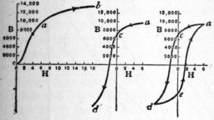
Fig. 11. Fig. 12. Fig. 13.
Induction and Hysteresis Curves.—Some typical induction curves, copied from a paper by Ewing (Proc. Inst. C.E. vol. cxxvi.), are given in figs. 11, 12 and 13. Fig. 11 shows the relation of B to H in a specimen which has never before been magnetized. The experiment may be made in two different ways: (1) the magnetizing current is increased by a series of sudden steps, each of which produces a ballistic throw, the value of B after any one throw being proportional to the sum of that and all the previous throws; (2) the magnetizing current having been brought to any desired value, is suddenly reversed, and the observed throw taken as measuring twice the actual induction. Fig. 12 shows the nature of the course taken by the curve when the magnetizing current, after having been raised to the value corresponding to the point a, is diminished by steps until it is nothing, and then gradually increased in the reverse direction. The downward course of the curve is, owing to hysteresis, strikingly different from its upward course, and when the magnetizing force has been reduced to zero, there is still remaining an induction of 7500 units. If the operation is again reversed, the upward course will be nearly, but not exactly, of the form shown by the line d e a, fig. 13. After a few repetitions of the reversal, the process becomes strictly cyclic, the upward and downward curves always following with precision the paths indicated in the figure. In order to establish the cyclic condition, it is sufficient to apply alternately the greatest positive and negative forces employed in the test (greatest H = about ±5 C.G.S. units in the case illustrated in the figure), an operation which is performed by simply reversing the direction of the maximum magnetizing current a few times.
The closed figure a c d e a is variously called a hysteresis curve or diagram or loop. The area ∫ H dB enclosed by it represents the work done in carrying a cubic centimetre of the iron through the corresponding magnetic cycle; expressed in ergs this work is 1/4π ∫ H dB.21 To quote an example given by J. A. Fleming, it requires about 18 foot-pounds of work to make a complete magnetic cycle in a cubic foot of wrought iron, strongly magnetized first one way and then the other, the work so expended taking the form of heat in the mass.
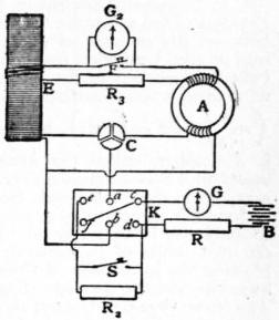
Fig. 14.
Fig. 14 shows diagrammatically a convenient arrangement described by Ewing (see Proc. Inst. C.E. vol. cxxvi., and Phil. Trans., 1893A, p. 987) for carrying out ballistic tests by which either the simple B-H curve (fig. 11) or the hysteresis curve (figs. 12 and 13) can be determined. The sample under test is prepared in the form of a ring A, upon which are wound the induction and the magnetizing coils; the latter should be wound evenly over the whole ring, though for the sake of clearness only part of the winding is indicated in the diagram. The magnetizing current, which is derived from the storage battery B, is regulated by the adjustable resistance R and measured by the galvanometer G. The current passes through the rocking key K, which, when thrown over to the right, places a in contact with c and b with d, and when thrown over to the left, places a in contact with e and b with f. When the switch S is closed, K acts simply as a commutator or current-reverser, but if K is thrown over from right to left while S is opened, not only is the current reversed, but its strength is at the same time diminished by the interposition of the adjustable resistance R2. The induction coil wound upon the ring is connected to the ballistic galvanometer G2 in series with a large permanent resistance R3. In the same circuit is also included the induction coil E, which is used for standardizing the galvanometer; this secondary coil is represented in the diagram by three turns of wire wound over a much longer primary coil. The short-circuit key F is kept closed except when an observation is about to be made; its object is to arrest the swing of the d’Arsonval galvanometer G2. By means of the three-way switch C the battery current may be sent either into the primary of E, for the purpose of calibrating the galvanometer, or into the magnetizing coil of the ring under test. When it is desired to obtain a simple curve of induction, such as that in fig. 11, S is kept permanently closed, and corresponding values of H and B are determined by one of the two methods already described, the strength of the battery-current being varied by means of the adjustable resistance R. When a hysteresis curve is to be obtained, the procedure is as follows: The current is first adjusted by means of R to such a strength as will fit it to produce the greatest + and − values of the magnetizing force which it is intended to apply in the course of the cycle; then it is reversed several times, and when the range of the galvanometer throws has become constant, half the extent of an excursion indicates the induction corresponding to the extreme value of H, and gives the point a in the curve fig. 12. The reversing key K having been put over to the left side, the short-circuit key S is suddenly opened; this inserts the resistance R, which has been suitably adjusted beforehand, and thus reduces the current and therefore the magnetizing force to a known value. The galvanometer throw which results from the change of current measures the amount by which the induction is reduced, and thus a second point on the curve is found. In a similar manner, by giving different values to the resistance R, any desired number of points between a and c in the curve can be determined. To continue the process, the key K is turned over to the right-hand side, and then, while S is open, is turned back, thereby not only reversing the direction of the current, but diminishing its strength by an amount depending upon the previous adjustment of R2. In this way points can be found lying anywhere between c and d of fig. 12, and the determination of the downward limb of the curve is therefore completed. As the return curve, shown in fig. 13, is merely an inverted copy of the other, no separate determination of it is necessary.
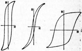
Fig. 15.
In fig. 15 (J. A. Fleming, Magnets and Electric Currents, p. 193) are shown three very different types of hysteresis curves, characteristic of the special qualities of the metals from which they were respectively obtained. The distinguishing feature of the first is the steepness of its outlines; this indicates that the induction increases rapidly in relation to the magnetic force, and hence the metal is well suited for the construction of dynamo magnets. The second has a very small area, showing that the work done in reversing the magnetization is small; the metal is therefore adapted for use in alternating current transformers. On the other hand, the form of the third curve, with its large intercepts on the axes of H and B, denotes that the specimen to which it relates possesses both retentiveness and coercive force in a high degree; such a metal would be chosen for making good permanent magnets.
Several arrangements have been devised for determining hysteresis more easily and expeditiously than is possible by the ballistic method. The best known is J. A. Ewing’s hysteresis-tester,22 which is specially intended for testing the sheet iron used in transformers. The sample, arranged as a bundle of rectangular strips, is caused to rotate about a central horizontal axis between the poles of an upright C-shaped magnet, which is supported near its middle upon knife-edges in such a manner that it can oscillate about an axis in a line with that about which the specimen rotates; the lower side of the magnet is weighted, to give it some stability. When the specimen rotates, the magnet is deflected from its upright position by an amount which depends upon the work done in a single complete rotation, and therefore upon the hysteresis. The deflection is indicated by a pointer upon a graduated scale, the readings being interpreted by comparison with two standard specimens supplied with the instrument. G. F. Searle and T. G. Bedford23 have introduced the method of measuring hysteresis by means of an electro-dynamometer used ballistically. The fixed and suspended coils of the dynamometer are respectively connected in series with the magnetizing solenoid and with a secondary wound upon the specimen. When the magnetizing current is twice reversed, so as to complete a cycle, the sum of the two deflections, multiplied by a factor depending upon the sectional area of the specimen and upon the constants of the apparatus, gives the hysteresis for a complete cycle in ergs per cubic centimetre. For specimens of large sectional area it is necessary to apply corrections in respect of the energy dissipated by eddy currents and in heating the secondary circuit. The method has been employed by the authors themselves in studying the effects of tension, torsion and circular magnetization, while R. L. Wills24 has made successful use of it in a research on the effects of temperature, a matter of great industrial importance.
C. P. Steinmetz (Electrician, 1891, 26, p. 261; 1892, 28, pp. 384, 408, 425) has called attention to a simple relation which appears to exist between the amount of energy dissipated in carrying a piece of iron or steel through a magnetic cycle and the limiting value of the induction reached in the cycle. Denoting by W the work in ergs done upon a cubic centimetre of the metal (= 1/4π ∫ H dB or ∫ H dI), he finds W = ηB1.6 approximately, where η is a number, called the hysteretic constant, depending upon the metal, and B is the maximum induction. The value of the constant η ranges in different metals from about 0.001 to 0.04; in soft iron and steel it is said to be generally not far from 0.002. Steinmetz’s formula may be tested by taking a series of hysteresis curves between different limits of B, measuring their areas by a planimeter, and plotting the logarithms of these divided by 4π as ordinates against logarithms of the corresponding maximum values of B as abscissae. The curve thus constructed should be a straight line inclined to the horizontal axis at an angle θ, the tangent of which is 1.6. Ewing and H. G. Klaassen (Phil. Trans., 1893, 184, 1017) have in this manner examined how nearly and within what range a formula of the type W = ηBε may be taken to represent the facts. The results of an example which they quote in detail may be briefly summarized as follows:—
Limits of B. Hysteretic Constant. η Index. ε (= tan θ) Degrees. θ
200 to 500 ... 1.9 62.25
500 to 1,000 ... 1.68 59.25
1,000 to 2,000 ... 1.55 57.25
2,000 to 8,000 0.01 1.475 55.75
8,000 to 14,000 0.00134 1.70 59.50
It is remarked by the experimenters that the value of the index ε is by no means constant, but changes in correspondence with the successive well-marked stages in the process of magnetization. But though a formula of this type has no physical significance, and cannot be accepted as an equation to the actual curve of W and B, it is, nevertheless, the case that by making the index ε = 1.6, and assigning a suitable value to η, a formula may be obtained giving an approximation to the truth which is sufficiently close for the ordinary purposes of electrical engineers, especially when the limiting value of B is neither very great nor very small. Alexander Siemens (Journ. Inst. Eng., 1894, 23, 229) states that in the hundreds of comparisons of test pieces which have been made at the works of his firm, Steinmetz’s law has been found to be practically correct.25 An interesting collection of W-B curves embodying the results of actual experiments by Ewing and Klaassen on different specimens of metal is given in fig. 16. It has been shown by Kennelly (Electrician, 1892, 28, 666) that Steinmetz’s formula gives approximately correct results in the case of nickel. Working with two different specimens, he found that the hysteresis loss in ergs per cubic centimetre (W) was fairly represented by 0.00125B1.6 and 0.00101B1.6 respectively, the maximum induction ranging from about 300 to 3000. The applicability of the law to cobalt has been investigated by Fleming (Phil. Mag., 1899, 48, 271), who used a ring of cast cobalt containing about 96% of the pure metal. The logarithmic curves which accompany his paper demonstrate that within wide ranges of maximum induction W = 0.01B1.6 = 0.527I1.62 very nearly. Fleming rightly regards it as not a little curious that for materials differing so much as this cast cobalt and soft annealed iron the hysteretic exponent should in both cases be so near to 1.6. After pointing out that, since the magnetization of the metal is the quantity really concerned, W is more appropriately expressed in terms of I, the magnetic moment per unit of volume, than of B, he suggests an experiment to determine whether the mechanical work required to effect the complete magnetic reversal of a crowd of small compass needles (representative of magnetic molecules) is proportional to the 1.6th power of the aggregate maximum magnetic moment before or after completion of the cycle.
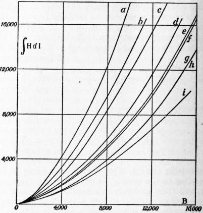
Fig. 16.
a, Fine steel wire 0.257 mm. diam. b, Fine iron wire 0.34 mm. diam. c, Fine iron wire 0.2475 mm. diam. d, Thin sheet iron 0.47 mm. thick. e, Iron wire 0.602 mm. diam. f, Iron wire 0.975 mm. diam. g, Sheet iron 1.95 mm. thick. h, Thin sheet iron 0.367 mm. thick. i. Very soft iron wire.
The experiments of K. Honda and S. Shimizu26 indicate that Steinmetz’s formula holds for nickel and annealed cobalt up to B = 3000, for cast cobalt and tungsten steel up to B = 8000, and for Swedish iron up to B = 18,000, the range being in all cases extended at the temperature of liquid air.
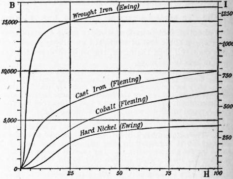
Fig. 17.
The diagram, fig. 17, contains examples of ascending induction curves characteristic of wrought iron, cast iron, cobalt and nickel. These are to be regarded merely as typical specimens, for the details of a curve depend largely upon the physical condition and purity of the material; but they show at a glance how far the several metals differ from and resemble one another as regards their magnetic properties. Curves of magnetization (which express the relation of I to H) have a close resemblance to those of induction; and, indeed, since B = H + 4πI, and 4πI (except in extreme fields) greatly exceeds H in numerical value, we may generally, without serious error, put I = B/4π, and transform curves of induction into curves of magnetization by merely altering the scale to which the ordinates are referred. A scale for the approximate transformation for the curves in fig. 12 is given at the right-hand side of the diagram, the greatest error introduced by neglecting H/4π not exceeding 0.6%. A study of such curves as these reveals the fact that there are three distinct stages in the process of magnetization. During the first stage, when the magnetizing force is small, the magnetization (or the induction) increases rather slowly with increasing force; this is well shown by the nickel curve in the diagram, but the effect would be no less conspicuous in the iron curve if the abscissae were plotted to a larger scale. During the second stage small increments of magnetizing force are attended by relatively large increments of magnetization, as is indicated by the steep ascent of the curve. Then the curve bends over, forming what is often called a “knee,” and a third stage is entered upon, during which a considerable increase of magnetizing force has little further effect upon the magnetization. When in this condition the metal is popularly said to be “saturated.” Under increasing magnetizing forces, greatly exceeding those comprised within the limits of the diagram, the magnetization does practically reach a limit, the maximum value being attained with a magnetizing force of less than 2000 for wrought iron and nickel, and less than 4000 for cast iron and cobalt. The induction, however, continues to increase indefinitely, though very slowly. These observations have an important bearing upon the molecular theory of magnetism, which will be referred to later.
The magnetic quality of a sample of iron depends very largely upon the purity and physical condition of the metal. The presence of ordinary impurities usually tends to diminish the permeability, though, as will appear later, the addition of small quantities of certain other substances is sometimes advantageous. A very pure form of iron, which from the method of its manufacture is called “steel,” is now extensively used for the construction of dynamo magnets; this metal sometimes contains not more than 0.3% of foreign substances, including carbon, and is magnetically superior to the best commercial wrought iron. The results of some comparative tests published by Ewing (Proc. Inst. C.E., 1896) are given in the accompanying table. Those in the second column are quoted from a paper by F. Lydall and A. W. Pocklington (Proc. Roy. Soc., 1892, 52, 228) and relate to an exceptional specimen containing nearly 99.9% of the pure metal.
Magnetic Force. Magnetic Induction.
Pure Iron. Low Moor Iron. Steel Forging. Steel Casting.
5 12,700 10,900 12,300 9,600
10 14,980 13,120 14,920 13,050
15 15,800 14,010 15,800 14,600
20 16,300 14,580 16,280 15,310
30 16,950 15,280 16,810 16,000
40 17,350 15,760 17,190 16,510
50 .. 16,060 17,500 16,900
60 .. 16,340 17,750 17,180
70 .. 16,580 17,970 17,400
80 .. 16,800 18,180 17,620
90 .. 17,000 18,390 17,830
100 .. 17,200 18,600 18,030
To secure the highest possible permeability it is essential that the iron should be softened by careful annealing. When it is mechanically hardened by hammering, rolling or wire-drawing its permeability may be greatly diminished, especially under a moderate magnetizing force. An experiment by Ewing showed that by the operation of stretching an annealed iron wire beyond the limits of elasticity the permeability under a magnetizing force of about 3 units was reduced by as much as 75%. Ewing has also studied the effect of vibration in conferring upon iron an apparent or spurious permeability of high value; this effort also is most conspicuous when the magnetizing force is weak. The permeability of a soft iron wire, which was tapped while subjected to a very small magnetizing force, rose to the enormous value of about 80,000 (Magnetic Induction, § 85). It follows that in testing iron for magnetic quality the greatest care must be exercised to guard the specimen against any accidental vibration.
Low hysteresis is the chief requisite for iron which is to be used for transformer cores, and it does not necessarily accompany high permeability. In response to the demand, manufacturers have succeeded in producing transformer plate in which the loss of energy due to hysteresis is exceedingly small. Tests of a sample supplied by Messrs. Sankey were found by Ewing to give the following results, which, however, are regarded as being unusually favourable. In a valuable collection of magnetic data (Proc. Inst. C.E., cxxvi.) H. F. Parshall quotes tests of six samples of iron, described as of good quality, which showed an average hysteresis loss of 3070 ergs per c.cm. per cycle at an induction of 8000, being 1.6 times the loss shown by Ewing’s specimen at the same induction.
Limits of Induction. Ergs per c.cm. per cycle. Watts per ℔. Frequency, 100.
2000 220 0.129
3000 410 0.242
4000 640 0.376
5000 910 0.535
6000 1200 0.710
7000 1520 0.890
8000 1900 1.120
9000 2310 1.360
The standard induction in reference to determinations of hysteresis is generally taken as 2500, while the loss is expressed in watts per ℔ at a frequency of 100 double reversals, or cycles, per second. In many experiments, however, different inductions and frequencies are employed, and the hysteresis-loss is often expressed as ergs per cubic centimetre per cycle and sometimes as horse-power per ton. In order to save arithmetical labour it is convenient to be provided with conversion factors for reducing variously expressed results to the standard form. The rate at which energy is lost being proportional to the frequency, it is obvious that the loss at frequency 100 may be deduced from that at any other frequency n by simply multiplying by 100/n. Taking the density of iron to be 7.7, the factor for reducing the loss in ergs per c.cm. to watts per ℔ with a frequency of 100 is 0.000589 (Ewing). Since 1 horse-power = 746 watts, and 1 ton = 2240 ℔, the factor for reducing horse-power per ton to watts per ℔ is 746/2240, or just 1/3. The loss for any induction B within the range for which Steinmetz’s law holds may be converted into that for the standard induction 2500 by dividing it by B1.6/25001.6. The values of this ratio for different values of B, as given by Fleming (Phil. Mag., 1897), are contained in the second column of the annexed table. The third column shows the relative amount of hysteresis deduced by Ewing as a general mean from actual tests of many samples (Journ. Inst. Elec. Eng., 1895). Incidentally, these two columns furnish an undesigned test of the accuracy of Steinmetz’s law: the greatest difference is little more than 1%.
Induction B. B1.6 25001.6 Observed relative Hysteresis.
2000 0.700 0.702
2500 1.000 1.000
3000 1.338 1.340
4000 2.118 2.128
5000 3.031 3.000
6000 4.058 4.022
7000 5.193 5.129
8000 6.430 6.384
Curves of Permeability and Susceptibility.—The relations of μ (= B/H) to B, and of κ (= I/H) to I may be instructively exhibited by means of curves, a method first employed by H. A. Rowland.27 The dotted curve for μ and B in fig. 18 is copied from Rowland’s paper. The actual experiment to which it relates was carried only as the point marked X, corresponding to a magnetizing force of 65, and an induction of nearly 17,000. Rowland, believing that the curve would continue to fall in a straight line meeting the horizontal axis, inferred that the induction corresponding to the point B—about 17,500—was the highest that could be produced by any magnetizing force, however great. It has, however, been shown that, if the magnetizing force is carried far enough, the curve always becomes convex to the axis instead of meeting it. The full line shows the result of an experiment in which the magnetizing force was carried up to 585,28 but though the force was thus increased ninefold, the induction only reached 19,800, and the ultimate value of the permeability was still as much as 33.9.
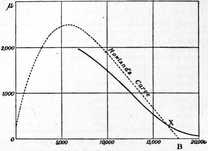
Fig. 18.
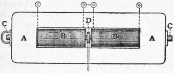
Fig. 19.
Ballistic Method with Yoke.—J. Hopkinson (Phil. Trans., 1885, 176, 455) introduced a modification of the usual ballistic arrangement which presents the following advantages; (1) very considerable magnetizing forces can be applied with ordinary means; (2) the samples to be tested, having the form of cylindrical bars, are more easily prepared than rings or wires; (3) the actual induction at any time can be measured, and not only changes of induction. On the other hand, a very high degree of accuracy is not claimed for the results. Fig. 19 shows the apparatus by which the ends of the bar are prevented from exerting any material demagnetizing force, while the permeance of the magnetic circuit is at the same time increased. A A, called the “yoke,” is a block of annealed wrought iron about 18 in. long, 6½ in. wide and 2 in. thick, through which is cut a rectangular opening to receive the two magnetizing coils B B. The test bar C C, which slides through holes bored in the yoke, is divided near the middle into two parts, the ends which come into contact being faced true and square. Between the magnetizing coils is a small induction coil D, which is connected with a ballistic galvanometer. The induction coil is carried upon the end of one portion of the test bar, and when this portion is suddenly drawn back the coil slips off and is pulled out of the field by an india-rubber spring. This causes a ballistic throw proportional to the induction through the bar at the moment when the two portions were separated. With such an arrangement it is possible to submit the sample to any series of magnetic forces, and to measure its magnetic state at the end. The uncertainty with which the results are affected depends chiefly upon the imperfect contact between the bar and the yoke and also between the ends of the divided bar. It is probable that Hopkinson did not attach sufficient importance to the demagnetizing action of the cut (cf. Ewing, Phil. Mag., Sept. 1888, p. 274), and that the values which he assigned to H are consequently somewhat too high. He applied his method with good effect, however, in testing a large number of commercial specimens of iron and steel, the magnetic constants of which are given in a table accompanying his paper. When it is not required to determine the residual magnetization there is no necessity to divide the sample bar, and ballistic tests may be made in the ordinary way—by steps or by reversals—the source of error due to the transverse cut thus being avoided. Ewing (Magnetic Induction, § 194) has devised an arrangement in which two similar test bars are placed side by side; each bar is surrounded by a magnetizing coil, the two coils being connected to give opposite directions of magnetization, and each pair of ends is connected by a short massive block of soft iron having holes bored through it to fit the bars, which are clamped in position by set-screws. Induction coils are wound on the middle parts of both bars, and are connected in series. With this arrangement it is possible to find the actual value of the magnetizing force, corrected for the effects of joints and other sources of error. Two sets of observations are taken, one when the blocks are fixed at the ends of the bars, and another when they are nearer together, the clear length of the bars between them and of the magnetizing coils being reduced to one-half. If H1 and H2 be the values of 4πin/l and 4πi′[(n/2) / (l/2)] for the same induction B, it can be shown that the true magnetizing force is H = H1 − (H2 − H1). The method, though tedious in operation, is very accurate, and is largely employed for determining the magnetic quality of bars intended to serve as standards.
Traction Methods.—The induction of the magnetization may be measured by observing the force required to draw apart the two portions of a divided rod or ring when held together by their mutual attraction. If a transverse cut is made through a bar whose magnetization is I and the two ends are placed in contact, it can be shown that this force is 2πI² dynes per unit of area (Mascart and Joubert, Electricity and Magnetism, § 322); and if the magnetization of the bar is due to an external field H produced by a magnetizing coil or otherwise, there is an additional force equal to HI. Thus the whole force, when the two portions of the bar are surrounded by a loosely-fitting magnetizing coil, is
F = 2πI² + HI
expressed as dynes per square centimetre. If each portion of the bar has an independent magnetizing coil wound tightly upon it, we have further to take into account the force due to the mutual action of the two magnetizing coils, which assists the forces already considered. This is equal to H²8π per unit of sectional area. In the case supposed therefore the total force per square centimetre is
F = 2πI² + HI + H²
8π
= (4πI + H)³
8π
= B² .
8π
The equation F = B²/8π is often said to express “Maxwell’s law of magnetic traction” (Maxwell, Electricity and Magnetism, §§ 642-646). It is, of course, true for permanent magnets, where H = 0, since then F = 2πI²; but if the magnetization is due to electric currents, the formula is only applicable in the special case when the mutual action of the two magnets upon one another is supplemented by the electromagnetic attraction between separate magnetizing coils rigidly attached to them.29
The traction method was first employed by S. Bidwell (Proc. Roy. Soc., 1886, 40, 486), who in 1886 published an account of some experiments in which the relation of magnetization to magnetic field was deduced from observations of the force in grammes weight which just sufficed to tear asunder the two halves of a divided ring electromagnet when known currents were passing through the coils. He made use of the expression
F = Wg = 2πI² + HI,
where W is the weight in grammes per square centimetre of sectional area, and g is the intensity of gravity which was taken as 981. The term for the attraction between the coils was omitted as negligibly small (see Phil. Mag., 1890, 29, 440). The values assigned to H were calculated from H = 2ni/r, and ranged from 3.9 to 585, but inasmuch as no account was taken of any demagnetizing action which might be due to the two transverse cuts, it is probable that they are somewhat too high. The results, nevertheless, agree very well with those for annealed wrought iron obtained by other methods. Below is given a selection from Bidwell’s tables, showing corresponding values of magnetizing force, weight supported, magnetization, induction, susceptibility and permeability:—
H. W. I. B. κ. μ.
3.9 2,210 587 7,390 151.0 1889.1
5.7 3,460 735 9,240 128.9 1621.3
10.3 5,400 918 11,550 89.1 1121.4
22.2 8,440 1147 14,450 51.7 650.9
40 9,680 1226 15,460 30.7 386.4
115 12,170 1370 17,330 11.9 150.7
208 13,810 1452 18,470 7.0 88.8
362 14,740 1489 19,080 4.1 52.7
465 15,275 1508 19,420 3.2 41.8
585 15,905 1530 19,820 2.6 33.9
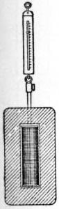
Fig. 20.
A few months later R. H. M. Bosanquet (Phil. Mag., 1886, 22, 535) experimented on the relation of tractive force to magnetic induction. Instead of a divided ring he employed a divided straight bar, each half of which was provided with a magnetizing coil. The joint was surrounded by an induction coil connected with a ballistic galvanometer, an arrangement which enabled him to make an independent measurement of the induction at the moment when the two portions of the bar were separated. He showed that there was, on the whole, a fair agreement between the values determined ballistically and those given by the formula B = √8πF. The greatest weight supported in the experiments was 14,600 grammes per square cm., and the corresponding induction 18,500 units. Taylor Jones subsequently found a good agreement between the theoretical and the observed values of the tractive force in fields ranging up to very high intensities (Phil. Mag., 1895, 39, 254, and 1896, 41, 153).
Permeameters.—Several instruments in which the traction method is applied have been devised for the rapid measurement of induction or of magnetization in commercial samples of iron and steel. The earliest of these is S. P. Thompson’s permeameter (Journ. Sci. Arts, 1890, 38, 885), which consists of a rectangular block of iron shaped like Hopkinson’s yoke, and slotted out in the same way to receive a magnetizing coil (fig. 20); the block is bored through at the upper end only, and its inner face opposite the hole is made quite flat and smooth. The sample has the form of a thin rod, one end of which is faced true; it is slipped into the magnetizing coil from above, and when the current is turned on its smooth end adheres tightly to the surface of the yoke. The force required to detach it is measured by a registering spring balance, which is clamped to the upper end of the rod, and thence the induction or the magnetization is deduced by applying the formula
(B − H)² / 8π = 2πI² = Pg / S,
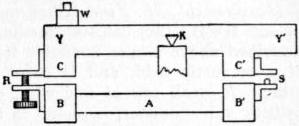
Fig. 21.
where P is the pull in grammes weight, S the sectional area of the rod in square cm., and g = 981. If the pull is measured in pounds and the area in square inches, the formula may be written B = 1317 × √P/S + H. The instrument exhibited by Thompson would, without undue heating, take a current of 30 amperes, which was sufficient to produce a magnetizing force of 1000 units. A testing apparatus of a similar type devised by Gisbert Kapp (Journ. Inst. Elec. Eng. xxiii. 199) differs only in a few details from Thompson’s permeameter. Ewing has described an arrangement in which the test bar has a soft-iron pole piece clamped to each of its ends; the pole pieces are joined by a long well-fitting block of iron, which is placed upon them (like the “keeper” of a magnet), and the induction is measured by the force required to detach the block. In all such measurements a correction should be made in respect of the demagnetizing force due to the joint, and unless the fit is very accurate the demagnetizing action will be variable. In the magnetic balance of du Bois (Magnetic Circuit, p. 346) the uncertainty arising from the presence of a joint is avoided, the force measured being that exerted between two pieces of iron separated from each other by a narrow air-gap of known width. The instrument is represented diagrammatically in fig. 21. The test-piece A, surrounded by a magnetizing coil, is clamped between two soft-iron blocks B, B′. Y Y′ is a soft iron yoke, which rocks upon knife-edges K and constitutes the beam of the balance. The yoke has two projecting pieces C, C′ at unequal distances from the knife-edges, and separated from the blocks B, B′ by narrow air-gaps. The play of the beam is limited by a stop S and a screw R, the latter being so adjusted that when the end Y of the beam is held down the two air-gaps are of equal width. W is a weight capable of sliding from end to end of the yoke along a graduated scale. When there is no magnetization, the yoke is in equilibrium; but as soon as the current is turned on the block C is drawn downwards as far as the screw R will allow, for, though the attractive forces F between B and C and between B′ and C′ are equal, the former has a greater moment. The weight W is moved along the scale until the yoke just tilts over upon the stop S; the distance of W from its zero position is then, as can easily be shown, proportional to F, and therefore to B², and approximately to I². The scale is graduated in such a manner that by multiplying the reading by a simple factor (generally 10 or 2) the absolute value of the magnetization is obtained. The actual magnetizing force H is of course less than that due to the coil; the corrections required are effected automatically by the use of a set of demagnetization lines drawn on a sheet of celluloid which is supplied with the instrument. The celluloid sheet is laid upon the squared paper, and in plotting a curve horizontal distances are reckoned from the proper demagnetization line instead of from the vertical axis. An improved but somewhat more complex form of the instrument is described in Ann. d. Phys., 1900, 2, 317.
In Ewing’s magnetic balance (Journ. Inst. Elec. Eng. 1898, 27, 526), the value of the magnetic induction corresponding to a single stated magnetizing force is directly read off on a divided scale. The specimen, which has the form of a turned rod, 4 in. long and ¼ in. in diameter, is laid across the poles of a horseshoe electromagnet, excited by a current of such strength as to produce in the rod a magnetizing force H = 20. One pole has a V-shaped notch for the rod to rest in; the surface of the other is slightly rounded, forming a portion of a cylinder, the axis of which is perpendicular to the direction of the length of the rod. The rod touches this pole at a single point, and is pulled away from it by the action of a lever, the long arm of which is graduated and carries a sliding weight. The position of the weight at the moment when contact is broken indicates the induction in the rod. The standard force H = 20 was selected as being sufficiently low to distinguish between good and bad specimens, and at the same time sufficiently high to make the order of merit the same as it would be under stronger forces.
Permeability Bridges.—Several pieces of apparatus have been invented for comparing the magnetic quality of a sample with that of a standard iron rod by a zero method, such as is employed in the comparison of electrical resistances by the Wheatstone bridge. An excellent instrument of the class is Ewing’s permeability bridge. The standard rod and the test specimen, which must be of the same dimensions, are placed side by side within two magnetizing coils, and each pair of adjacent ends is joined by a short rectangular block or “yoke” of soft iron. An iron bar shaped like an inverted projects upwards from each of the yokes, the horizontal portions of the bars being parallel to the rods, and nearly meeting at a height of about 8 in. above them (thus ). A compass needle placed in the gap serves to detect any flow of induction that may exist between the bent bars. For simplicity of calculation, the clear length of each rod between the yokes is made 12.56 (= 4π) centimetres, while the coil surrounding the standard bar contains 100 turns; hence the magnetizing force due to a current of n amperes will be 10n C.G.S. units. The effective number of turns in the coil surrounding the test rod can be varied by means of three dial switches (for hundreds, tens and units), which also introduce compensating resistances as the number of effective turns in the coil is reduced, thus keeping the total resistance of the circuit constant. The two coils are connected in series, the same current passing through both. Suppose the switches to be adjusted so that the effective number of turns in the variable coil is 100; the magnetizing forces in the two coils will then be equal, and if the test rod is of the same quality as the standard, the flow of induction will be confined entirely to the iron circuit, the two yokes will be at the same magnetic potential, and the compass needle will not be affected. If, however, the permeability of the test rod differs from that of the standard, the number of lines of induction flowing in opposite directions through the two rods will differ, and the excess will flow from one yoke to the other, partly through the air, and partly along the path provided by the bent bars, deflecting the compass needle. But a balance may still be obtained by altering the effective number of turns in the test coil, and thus increasing or decreasing the magnetizing force acting on the test rod, till the induction in the two rods is the same, a condition which is fulfilled when reversal of the current has no effect on the compass needle. Let m be the number of turns in use, and H1 and H2 the magnetizing forces which produce the same induction B in the test and the standard rods respectively; then H1 = H2 × m/100. The value of B which corresponds to H2m/100 can be found from the (B, H) curve for the standard, which is assumed to have been determined; and this same value corresponds to the force H in the case of the test bar. Thus any desired number of corresponding values of H and B can be easily and quickly found.


Measurement of Field Strength. Exploring Coil.—Since in air B = H, the ballistic method of measuring induction described above is also available for determining the strength of a magnetic field, and is more often employed than any other. A small coil of fine wire, connected in series with a ballistic galvanometer, is placed in the field, with its windings perpendicular to the lines of force, and then suddenly reversed or withdrawn from the field, the integral electromotive force being twice as great in the first case as in the second. The strength of the field is proportional to the swing of the galvanometer-needle, and, when the galvanometer is calibrated, can be expressed in C.G.S. units. Convenient arrangements have been introduced whereby the coil is reversed or withdrawn from the field by the action of a spring.
Bismuth Resistance.—The fact, which will be referred to later, that the electrical resistance of bismuth is very greatly affected by a magnetic field has been applied in the construction of apparatus for measuring field intensity. A little instrument, supplied by Hartmann and Braun, contains a short length of fine bismuth wire wound into a flat double spiral, half an inch or thereabouts in diameter, and attached to a long ebonite handle. Unfortunately the effects of magnetization upon the specific resistance of bismuth vary enormously with changes of temperature; it is therefore necessary to take two readings of the resistance, one when the spiral is in the magnetic field, the other when it is outside.
Electric Circuit.—If a coil of insulated wire is suspended so that it is in stable equilibrium when its plane is parallel to the direction of a magnetic field, the transmission of a known electric current through the coil will cause it to be deflected through an angle which is a function of the field intensity.
One of the neatest applications of this principle is that described by Edser and Stansfield (Phil. Mag., 1893, 34, 186), and used by them to test the stray fields of dynamos. An oblong coil about an inch in length is suspended from each end by thin strips of rolled German silver wire, one of which is connected with a spiral spring for regulating the tension, the other being attached to a torsion-head. Inside the torsion-head is a commutator for automatically reversing the current, so that readings may be taken on each side of zero, and the arrangement is such that when the torsion-head is exactly at zero the current is interrupted. To take a reading the torsion-head is turned until an aluminium pointer attached to the coil is brought to the zero position on a small scale; the strength of the field is then proportional to the angular torsion. The small current required is supplied to the coil from a single dry cell. The advantages of portability, very considerable range (from H = 1 upwards), and fair accuracy are claimed for the instrument.
Polarized Light.—The intensity of a field may be measured by the rotation of the plane of polarization of light passing in the direction of the magnetic force through a transparent substance. If the field is uniform, H = θ/ωd, where θ is the rotation, d the thickness of the substance arranged as a plate at right angles to the direction of the field, and ω Verdet’s constant for the substance.
For the practical measurement of field intensity du Bois has used plates of the densest Jena flint glass. These are preferably made slightly wedge-shape, to avoid the inconvenience resulting from multiple internal reflections, and they must necessarily be rather thin, so that double refractions due to internal strain may not exert a disturbing influence. Since Verdet’s constant is somewhat uncertain for different batches of glass even of the same quality, each plate should be standardized in a field of known intensity. As the source of monochromatic light a bright sodium burner is used, and the rotation, which is exactly proportional to H, is measured by an accurate polarimeter. Such a plate about 1 mm. in thickness is said to be adapted for measuring fields of the order of 1000 units. A part of one surface of the plate may be silvered, so that the polarized ray, after having once traversed the glass, is reflected back again; the rotation is thus doubled, and moreover, the arrangement is, for certain experiments, more convenient than the other.
4. Magnetization in Strong Fields
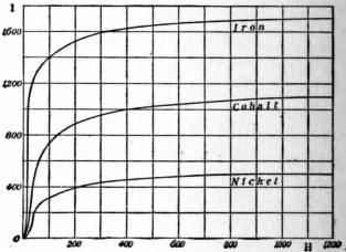
Fig. 22.
Fields due to Coils.—The most generally convenient arrangement for producing such magnetic fields as are required for experimental purposes is undoubtedly a coil of wire through which an electric current can be caused to flow. The field due to a coil can be made as nearly uniform as we please throughout a considerable space; its intensity, when the constants of the coil are known, can be calculated with ease and certainty and may be varied at will through wide ranges, while the apparatus required is of the simplest character and can be readily constructed to suit special purposes. But when exceptionally strong fields are desired, the use of a coil is limited by the heating effect of the magnetizing current, the quantity of heat generated per unit of time in a coil of given dimensions increasing as the square of the magnetic field produced in its interior. In experiments on magnetic strains carried out by H. Nagaoka and K. Honda (Phil. Mag., 1900, 49, 329) the intensity of the highest field reached in the interior of a coil was 2200 units; this is probably the strongest field produced by a coil which has hitherto been employed in experimental work. In 1890 some experiments in which a coil was used were made by du Bois (Phil. Mag., 1890, 29, 253, 293) on the magnetization of iron, nickel, and cobalt under forces ranging from about 100 to 1250 units. Since the demagnetizing factor was 0.052, the strongest field due to the coil was about 1340; but though arrangements were provided for cooling the apparatus by means of ice, great difficulty was experienced owing to heating. Du Bois’s results, which, as given in his papers, show the relation of H to the magnetic moment per unit of mass, have been reduced by Ewing to the usual form, and are indicated in fig. 22, the earlier portions of the curves being sketched in from other data.
Fields due to Electromagnets.—The problem of determining the magnetization of iron and other metals in the strong fields formed between the poles of an electromagnet was first attacked by J. A. Ewing and W. Low. An account of their preliminary experiments by what they call the isthmus method was published in 1887 (Proc. Roy. Soc. 42, 200), and in the following year they described a more complete and perfect series (Phil. Trans., 1889, 180, 221).
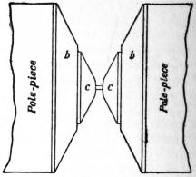
Fig. 23.
The sample to be inserted between the magnet poles was prepared in the form of a bobbin resembling an ordinary cotton reel, with a short narrow neck (constituting the “isthmus”) and conical ends. Upon the central neck was wound a coil consisting of one or two layers of very fine wire, which was connected with a ballistic galvanometer for measuring the induction in the iron; outside this coil, and separated from it by a small and accurately determined distance, a second coil was wound, serving to measure the induction in the iron, together with that in a small space surrounding it. The difference of the ballastic throws taken with the two coils measured the intensity of the field in the space around the iron, and it also enabled a correction to be made for the non-ferrous space between the iron neck and the centre of the thickness of the inner coil. The pole pieces of the electromagnet (see fig. 23) were furnished with a pair of truncated cones b b, of soft iron forming an extension of the conical ends of the bobbin c. The most suitable form for the pole faces is investigated in the paper, and the conclusion arrived at is that to produce the greatest concentration of force upon the central neck, the cones should have a common vertex in the middle of the neck with a semi-vertical angle of 54° 44′, while the condition for a uniform field is satisfied when the cones have a semi-vertical angle of 39° 14′; in the latter case the magnetic force in the air just outside is sensibly equal to that within the neck. A pair of cones having a semi-vertical angle of 45° were considered to combine high concentrative power with a sufficient approximation to uniformity of field. In most of the experiments the measurements were made by suddenly withdrawing the bobbin from its place between the pole pieces. Two groups of observations were recorded, one giving the induction in the inner coil and the other that in the outer coil. The value of the residual induction which persisted when the bobbin was drawn out was added to that of the induction measured, and thus the total induction in the iron was determined. The highest induction reached in these experiments was 45,350 units, more than twice the value of any previously recorded. The corresponding intensity of the outside field was 24,500, but, owing to the wide angle of the cones used (about 2 × 63°), this was probably greater than the value of the magnetic force within the metal. The following table shows some results of other experiments in which H was believed to have sensibly the same value inside as outside the metal. Values of I are derived from (B − H)/4π and of μ from B/H.
Metal. H B I μ
Swedish Iron 1,490 22,650 1680 15.20
6,070 27,130 1680 4.47
8,600 30,270 1720 3.52
19,450 40,820 1700 2.10
19,880 41,140 1700 2.07
Cast Iron 4,560 20,070 1230 4.40
13,460 28,710 1210 2.13
16,200 30,920 1170 1.91
16,900 31,760 1180 1.88
Tool Steel 6,210 25,480 1530 4.10
9,970 29,650 1570 2.97
12,170 31,620 1550 2.60
14,660 34,550 1580 2.36
15,530 35,820 1610 2.31
Hard Nickel 2,220 7,100 390 3.20
4,440 9,210 380 2.09
7,940 12,970 400 1.63
14,660 19,640 400 1.34
16,000 21,070 400 1.32
Cobalt 1,350 16,000 1260 12.73
4,040 18,870 1280 4.98
8,930 23,890 1290 2.82
14,990 30,210 1310 2.10
These results are of extreme interest, for they show that under sufficiently strong magnetizing forces the intensity of magnetization I reaches a maximum value, as required by W. E. Weber’s theory of molecular magnetism. There appears to be no definite limit to the value to which the induction B may be raised, but the magnetization I attains a true saturation value under magnetizing forces which are in most cases comparatively moderate. Thus the magnetization which the sample of Swedish iron received in a field of 1490 was not increased (beyond the limits of experimental error) when the intensity of the field was multiplied more than thirteen-fold, though the induction was nearly doubled. When the saturation value of I has been reached, the relation of magnetic induction to magnetic force may be expressed by
B = H + constant.
The annexed table gives the saturation values of I for the particular metals examined by Ewing and Low:—
Saturation Value of I
Wrought iron 1,700
Cast iron 1,240
Nickel (0.75% iron) 515
Nickel (0.56% iron) 400
Cobalt (1.66% iron) 1,300
It is shown in the paper that the greatest possible force which the isthmus method can apply at a point in the axis of the bobbin is
F = 11.137 Is log10 b/a,
Is being the saturation value of the magnet poles, a the radius of the neck on which the cones converge, and b the radius of the bases of the cones.
Some experiments made by H. du Bois (Phil. Mag., 1890, 29, 293) with an electromagnet specially designed for the production of strong fields, confirm Ewing’s results for iron, nickel and cobalt. The method employed did not admit of the production of such high magnetizing forces, but was of special interest in that both B and I were measured optically—B by means of the rotation of a polarized ray inside a glass plate, as before described, and I by the rotation of a polarized ray reflected from the polished surface of the magnetized metal (see “Kerr’s constant,” Magneto-Optics). H(= B − 4πI) was calculated from corresponding values of I and B. Taylor Jones (Wied. Ann., 1896, 57, 258, and Phil. Mag., 1896, 41, 153), working with du Bois’s electromagnet and using a modification of the isthmus method, succeeded in pushing the induction B up to 74,200 with H = 51,600, the corresponding value of I being 1798, and of μ only 1.44. The diameter of the isthmus was 0.241 mm., and the electromagnet was excited by a current of 40 amperes.
Tractive Force of a Magnet.—Closely connected with the results just discussed is the question what is the greatest tractive force that can be exerted by a magnet. In the year 1852 J. P. Joule (Phil. Mag., 1852, 3, 32) expressed the opinion that no “force of current could give an attraction equal to 200 ℔ per sq. in.,” or 14,000 grms. per square centimetre, and a similar view prevailed among high authorities more than twenty years later. For the greatest possible “lifting power” of permanent magnets this estimate is probably not very far from the truth, but it is now clearly understood that the force which can be exerted by an electromagnet, or by a pair of electromagnets with opposite poles in contact, is only limited by the greatest value to which it is practically possible to raise the magnetizing force H. This is at once evident when the tractive force due to magnetization is expressed as 2πI² + HI. For fields of moderate intensity the first term of the expression is the more important, but when the value of H exceeds 12,000 or thereabouts, the second preponderates, and with the highest values that have been actually obtained, HI is several times greater than 2πI². If H could be increased without limit, so also could the tractive force. The following table shows the greatest “lifting powers” experimentally reached at the dates mentioned:—
Observer. Kilos per sq. cm. ℔ per sq. in. Date.
Joule 12.3 175 1852
Bidwell 15.9 226 1886
Wilde 26.8 381 1891
T. Jones 114.9 1634 1896
5. Magnetization in Very Weak Fields
Some interesting observations have been made of the effects produced by very small magnetic forces. It was first pointed out by C. Baur (Wied. Ann., 1880, 11, 399) that in weak fields the relation of the magnetization I to the magnetizing force H is approximately expressed by an equation of the form
I = aH + bH²,
or
κ = I / H = a + bH,
whence it appears that within the limits of Baur’s experiments the magnetization curve is a parabola, and the susceptibility curve an inclined straight line, κ being therefore a known function of H. If these equations could be assumed to hold when H is indefinitely small, it would follow that κ has a finite initial value, from which there would be no appreciable deviation in fields so weak that bH was negligibly small in comparison with a. Such an assumption could not, however, without dangerous extrapolation, be founded upon the results of Baur’s experiments, which did not go far enough to justify it. In some experiments carried out in 1887, Lord Rayleigh (Phil. Mag., 1887, 23, 225) approached very much more nearly than Baur to the zero of magnetic force. Using an unannealed Swedish iron wire, he found that when H was gradually diminished from 0.04 to 0.00004 C.G.S. unit, the ratio of magnetization to magnetizing force remained sensibly constant at 6.4, which may therefore with great probability be assumed to represent the initial value of κ for the specimen in question. Experiments with annealed iron gave less satisfactory results, on account of the slowness with which the metal settled down into a new magnetic state, thus causing a “drift” of the magnetometer needle, which sometimes persisted for several seconds. Apart from this complication, it appeared that I was proportional to H when the value of H was less than 0.02.
The observations of Baur and Rayleigh have been confirmed and discussed by (amongst others) W. Schmidt (Wied. Ann., 1895, 54, 655), who found the limiting values of κ to be 7.5 to 9.5 for iron, and 11.2 to 13.5 for steel, remaining constant up to H = .06; by P. Culmann (Elekt. Zeit., 1893, 14, 345; Wied. Ann., 1895, 56, 602); and by L. Holborn (Berl. Ber., 1897, p. 95, and Wied. Ann., 1897, 61, 281). The latter gives values of the constants a and b for different samples of iron and steel, some of which are shown in the following table:—
κ = a + bH
Metal. a b
English tungsten steel 8.90 0.264
Tungsten steel, hardened 2.23 0.032
Silver steel 8.66 0.384
Tool steel 8.30 0.400
Refined steel 11.28 1.92
Cast iron 3.16 0.236
Soft iron 16.6 18.6
Hard drawn iron 5.88 1.76
For most samples of steel the straight-line law was found to hold approximately up to H = 3; in the case of iron and of soft steel the approximation was less close.
The behaviour of nickel in weak fields has been observed by Ewing (Phil. Trans., 1888, 179A, 325), who found that the initial value of κ was 1.7, and that it remained sensibly constant until H had reached a value of about five units. While therefore the initial susceptibility of nickel is less than that of iron and steel, the range of magnetic force within which it is approximately constant is about one hundred times greater. Ewing has also made a careful study (Proc. Roy. Soc., 1889, 46, 269) of “magnetic viscosity” under small forces—the cause of the magnetometer “drift” referred to by Rayleigh. On the application of a small magnetizing force to a bar of soft annealed iron, a certain intensity of magnetization is instantly produced; this, however, does not remain constant, but slowly increases for some seconds or even minutes, and may ultimately attain a value nearly twice as great as that observed immediately after the force was applied.30 When the magnetizing current is broken, the magnetization at once undergoes considerable diminution, then gradually falls to zero, and a similar sudden change followed by a slow one is observed when a feeble current is reversed. Ewing draws attention to a curious consequence of this time-lag. By the alternate application and withdrawal of a small magnetizing force a cyclic condition may be established in an iron rod. If now the alternations are performed so rapidly that time is not allowed for more than the first sudden change in the magnetization, there will be no hysteresis loss, the magnetization exactly following the magnetizing force. Further, if the alternations take place so slowly that the full maximum and minimum values of the magnetization are reached in the intervals between the reversals, there will again be no dissipation of energy. But at any intermediate frequency the ascending and descending curves of magnetization will enclose a space, and energy will be dissipated. It is remarkable that the phenomena of magnetic viscosity are much more evident in a thick rod than in a thin wire, or even in a large bundle of thin wires. In hardened iron and steel the effect can scarcely be detected, and in weak fields these metals exhibit no magnetic hysteresis of any kind.
6. Changes of Dimensions Attending Magnetization
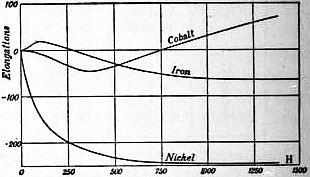
Fig. 24.
It is well known that the form of a piece of ferromagnetic metal is in general slightly changed by magnetization. The phenomenon was first noticed by J. P. Joule, who in 1842 and 1847 described some experiments which he had made upon bars of iron and steel. His observations, were for the most part confirmed by a number of subsequent workers, notably by A. M. Mayer; but with the single exception of the discovery by W. F. Barrett in 1882 that a nickel bar contracts when magnetized, nothing of importance was added by Joule’s results for nearly forty years. Later researches have however thrown much new light upon a class of phenomena which cannot fail to have an important bearing upon the complete theory of molecular magnetism.31 According to Joule’s observations, the length of a bar of iron or soft steel was increased by magnetization, the elongation being proportional up to a certain point to the square of the intensity of magnetization; but when the “saturation point” was approached the elongation was less than this law would require, and a stage was finally reached at which further increase of the magnetizing force produced little or no effect upon the length. From data contained in Joule’s paper it may be calculated that the strongest external field H0 produced by his coil was about 126 C.G.S. units, but since the dimensional ratio of his bars was comparatively small, the actual magnetizing force H must have been materially below that value. In 1885 it was shown by Bidwell, in the first of a series of papers on the subject, that if the magnetizing force is pushed beyond the point at which Joule discontinued his experiments, the extension of the bar does not remain unchanged, but becomes gradually less and less, until the bar, after first returning to its original length, ultimately becomes actually shorter than when in the unmagnetized condition. The elongation is generally found to reach a maximum under a magnetizing force of 50 to 120 units, and to vanish under a force of 200 to 400, retraction occurring when still higher forces are applied. In order to meet the objection that the phenomenon might be due to electromagnetic action between the coil and the rod, Bidwell made some experiments with iron rings, and found that the length of their diameters varied under magnetization in precisely the same manner as the length of a straight rod. Experiments were afterwards made with rods of iron, nickel, and cobalt, the external field being carried up to the high value of 1500 units. The results are indicated in Fig. 24. It appears that the contraction which followed the initial extension of the iron reached a limit in fields of 1000 or 1100. Nickel exhibited retraction from the very beginning (as observed by Barrett), its greatest change of length considerably exceeding that undergone by iron; in a field of 800 the original length was diminished by as much as 1/40,000 part, but stronger forces failed to produce any further effect. The curve for cobalt is a very remarkable one. Little or no change of length was observed until the strength of the field H0 reached about 50; then the rod began to contract, and after passing a minimum at H0 = 400, recovered its original length at H0 = 750; beyond this point there was extension, the amount of which was still increasing fast when the experiment was stopped at H0 = 1400. Similar results were obtained with three different samples of the metal. Roughly speaking, therefore, cobalt behaves oppositely to iron.
Joule and others experimented with hardened steel, but failed to find a key to the results they obtained, which are rather complex, and have been thought to be inconsistent. The truth appears to be that a hardened steel rod generally behaves like one of iron or soft steel in first undergoing extension under increasing magnetizing force, and recovering its original length when the force has reached a certain critical value, beyond which there is contraction. But this “critical value” of the force is found to depend in an unexpected manner upon the hardness of the steel; the critical value diminishes as the hardness becomes greater up to a certain point, corresponding to a yellow temper, after which it increases and with the hardest steel becomes very high. For steel which has been made red-hot, suddenly cooled, and then let down to a yellow temper, the critical value of the magnetizing force is smaller than for steel which is either softer or harder; it is indeed so small that the metal contracts like nickel even under weak magnetizing forces, without undergoing any preliminary extension that can be detected.
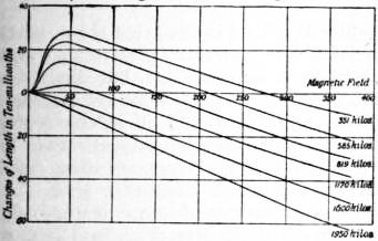
Fig. 25.
Joule also made experiments upon iron wires under tension, and drew the erroneous inference (which has been often quoted as if it were a demonstrated fact) that under a certain critical tension (differing for different specimens of iron but independent of the magnetizing force) magnetization would produce no effect whatever upon the dimensions of the wire. What actually happens when an iron wire is loaded with various weights is clearly shown in Fig. 25. Increased tension merely has the effect of diminishing the maximum elongation and hastening the contraction; with the two greatest loads used in the experiment there was indeed no preliminary extension at all.32 The effects of tension upon the behaviour of a nickel wire are of a less simple character. In weak fields the magnetic contraction is always diminished by pulling stress; in strong fields the contraction increases under a small load and diminishes under a heavy one. Cobalt, curiously enough, was found to be quite unaffected by tensile stress.
Certain experiments by C. G. Knott on magnetic twist, which will be referred to later, led him to form the conclusion that in an iron wire carrying an electric current the magnetic elongation would be increased. This forecast was shown by Bidwell to be well founded. The effect produced by a current is exactly opposite to that of tension, raising the elongation curve instead of depressing it. In the case of a wire 0.75 mm. in diameter the maximum elongation was nearly doubled when a current of two amperes was passing through the iron, while the “critical value” of the field was increased from 130 to 200. Yet notwithstanding this enormous effect in iron, the action of a current upon nickel and cobalt turned out to be almost inappreciable.
Some experiments were next undertaken with the view of ascertaining how far magnetic changes of length in iron were dependent upon the hardness of the metal, and the unexpected result was arrived at that softening produces the same effect as tensile stress; it depresses the elongation curve, diminishing the maximum extension, and reducing the “critical value” of the magnetizing force. A thoroughly well annealed ring of soft iron indeed showed no extension at all, beginning to contract, like nickel, under the smallest magnetizing forces. The experiments were not sufficiently numerous to indicate whether, as is possible, there is a critical degree of hardness for which the height of the elongation curve is a maximum.
Finally, experiments were made to ascertain the effect of magnetization upon the dimensions of iron rings in directions perpendicular to the magnetization, and upon the volume of the rings.33 It was found that the curve showing the relation of transverse changes of dimensions to magnetizing force was similar in general character to the familiar elongation curves, but the signs were reversed; the curve was inverted, indicating at first retraction, which, after passing a maximum and vanishing in a critical field, was succeeded by elongation. The curve showing the circumferential (or longitudinal) changes was also plotted, and from the two curves thus obtained it was easy, on the assumption that the metal was isotropic in directions at right angles to the magnetization, to calculate changes of volume; for if circumferential elongation be denoted by l1, and transverse elongation by l2, then the cubical dilatation (+ or −) = l1 + 2l2 approximately. If l1 were exactly equal to -2l2 for all values of the magnetizing force, it is clear that the volume of the ring would be unaffected by magnetization. In the case of the ring in question, the circumferential changes were in weak fields less than twice as great as the transverse ones, while in strong fields they were more than twice as great; under increasing magnetic force therefore the volume of the ring was first diminished, then it regained its original value (for H = 90), and ultimately increased. It was also shown that annealing, which has such a large effect upon circumferential (or longitudinal) changes, has almost none upon transverse ones. Hence the changes of volume undergone by a given sample of wrought iron under increasing magnetization must depend largely upon the state of the metal as regards hardness; there may be always contraction, or always expansion, or first one and then the other.
Most of the experiments described above have been repeated and the results confirmed by other workers, some of whom have added fresh observations. The complicated hysteresis effects which attend magnetic elongation and retraction have been studied by H. Nagaoka, who also, in conjunction with K. Honda, measured the changes of length of various metals shaped in the form of ovoids instead of cylindrical rods, and determined the magnetization curves for the same specimens; a higher degree of accuracy was thus attained, and satisfactory data were provided for testing theories. Among other things, it was found that the behaviour of cast cobalt was entirely changed by annealing; the sinuous curve shown in Fig. 24 was converted into an almost perfectly straight line passing through the origin, and lying below the horizontal axis; while the permeability of the metal was greatly diminished by the operation. They also tested several varieties of nickel-steel in the form of both ovoids and wires. With a sample containing 25% of nickel no appreciable change was detected; others containing larger percentages, and tested in fields up to 2000, all exhibited elongation, which tended to an asymptotic value as the field was increased. The influence of temperature varying between wide limits has formed the subject of a research by K. Honda and S. Shimizu. For soft iron, tungsten-steel and nickel little difference appeared to result from lowering the temperature down to −186° C. (the temperature of liquid air); at sufficiently high temperatures, 600° to 1000° or more, it was remarked that the changes of length in iron, steel and cobalt tended in every case to become proportional to the magnetic force, the curves being nearly straight lines entirely above the axis. The retraction of nickel was diminished by rising temperature, and at 400° had almost vanished. The influence of high temperature on cobalt was very remarkable, completely altering the character of the change of length: the curves for annealed cobalt show that at 450° this metal behaves just like iron at ordinary temperatures, lengthening in fields up to about 300 and contracting in stronger ones. The same physicists have made some additional experiments upon the effect of tension on magnetic change of length. Bidwell’s results for iron and nickel were confirmed, and it was further shown that the elongation of nickel-steel was very greatly diminished by tension; when magnetized under very heavy loads, the wire was indeed found to undergo slight contraction. Honda subjected tubes of iron, steel and nickel to the simultaneous action of circular and longitudinal fields, and observed the changes of length when one of the fields was varied while the other remained constant at different successive values from zero upwards. The experimental results agreed in sign though not in magnitude with those calculated from the changes produced by simple longitudinal magnetization, discrepancies being partly accounted for by the fact that the metals employed were not actually isotropic. Heusler’s alloy has been tested for change of length by L. Austin, who found continuous elongation with increasing fields, the curves obtained bearing some resemblance to curves of magnetization.
As regards the effect of magnetization upon volume there are some discrepancies. Nagaoka and Honda, who employed a fluid dilatometer, found that the volume of several specimens of iron, steel and nickel was always slightly increased, no diminution being indicated in low fields; cobalt, on the other hand, was diminished in volume, and the amount of the change, though still very small, was greater than that shown by the other metals. Various nickel-steels all expanded under magnetization, the increase being generally considerable and proportional to the field; in the case of an alloy containing 29% of nickel the change was nearly 40 times greater than in soft iron. C. G. Knott, who made an exhaustive series of experiments upon various metals in the form of tubes, concluded that in iron there was always a slight increase of volume, and in nickel and cobalt a slight decrease. It is uncertain how far these various results are dependent upon the physical condition of the metals.
Attempts have been made to explain magnetic deformation by various theories of magnetic stress,34 notably that elaborated by G. R. Kirchhoff (Wied. Ann., 1885, 24, 52, and 1885, 25, 601), but so far with imperfect success. E. Taylor Jones showed in 1897 that only a small proportion of the contraction exhibited by a nickel wire when magnetized could be accounted for on Kirchhoff’s theory from the observed effects of pulling stress upon magnetization; and in a more extended series of observations Nagaoka and Honda found wide quantitative divergences between the results of experiment and calculation, though in nearly all cases there was agreement as to quality. They consider, however, that Kirchhoff’s theory, which assumes change of magnetization to be simply proportional to strain, is still in its infancy, the present stage of its evolution being perhaps comparable with that reached by the theory of magnetization at the time when the ratio I/H was supposed to be constant. In the light of future researches further development may reasonably be expected.
It has been suggested35 that an iron rod under magnetization may be in the same condition as if under a mechanically applied longitudinal stress tending to shorten the iron. If a long magnetized rod is divided transversely and the cut ends placed nearly in contact, the magnetic force inside the narrow air gap will be B = H + 4πI. The force acting on the magnetism of one of the faces, and urging this face towards the other, will be less than B by 2πI, the part of the total force due to the first face itself; hence the force per unit of area with which the faces would press against each other if in contact is
P = (B − 2πI) I = 2πI² + HI = (B² − H²) / 8π.
The width of the gap may be diminished until it is no greater than the distance between two neighbouring molecules, when it will cease to be distinguishable, but, assuming the molecular theory of magnetism to be true, the above statement will still hold good for the intermolecular gap. The same pressure P will be exerted across any imaginary section of a magnetized rod, the stress being sustained by the intermolecular springs, whatever their physical nature may be, to which the elasticity of the metal is due. The whole of the rod will therefore be subject to a compressive longitudinal stress P, the associated contraction R, expressed as a fraction of the original length, being
R = P / M = (B² − H²) / 8πM,
where M is Young’s modulus. This was found to be insufficient to account for the whole of the retraction exhibited by iron in strong fields, but it was pointed out by L. T. More36 that R ought to be regarded as a “correction” to be applied to the results of experiments on magnetic change of length, the magnetic stress being no less an extraneous effect than a stress applied mechanically. Those who support this view generally speak of the stress as “Maxwell’s stress,” and assume its value to be B2/8π. The stress in question seems, however, to be quite unconnected with the “stress in the medium” contemplated by Maxwell, and its value is not exactly B2/8π except in the particular case of a permanent ring magnet, when H = O. Further, Maxwell’s stress is a tension along the lines of force, and is equal to B2/8π only when B = H, and there is no magnetization.37 Some writers have indeed contended that the stress in magnetized iron is not compressive, but tensile, even when, as in the case of a ring-magnet, there are no free ends. The point at issue has an important bearing upon the possible correlation of magnetic phenomena, but, though it has given rise to much discussion, no accepted conclusion has yet been reached.38
7. Effects of Mechanical Stress upon Magnetization
The effects of traction, compression and torsion in relation to magnetism have formed the subject of much patient investigation, especially at the hands of J. A. Ewing, C. G. Knott and the indefatigable physicists of Tokyo University. The results of their experiments embrace a multiplicity of details of which it is impossible to give an adequate summary. Only a few of the most important can be mentioned here; the reader who wishes for fuller information should consult the original papers.39
It was first discovered by E. Villari in 1868 that the magnetic susceptibility of an iron wire was increased by stretching when the magnetization was below a certain value, but diminished when that value was exceeded; this phenomenon has been termed by Lord Kelvin, who discovered it independently, the “Villari reversal,” the value of the magnetization for which stretching by a given load produces no effect being known as the “Villari critical point” for that load. The Villari critical point for a given sample of iron is reached with a smaller magnetizing force when the stretching load is great than when it is small; the reversal also occurs with smaller loads and with weaker fields when the iron is soft than when it is hard. The following table shows the values of I and H corresponding to the Villari critical point in some of Ewing’s experiments:—
Soft Iron. Hard Iron.
Kilos per sq. mm. I. H. Kilos per sq. mm. I. H.
2.15 1220 7.3 27.6 1180 34
4.3 1040 4.3 32.2 1150 32
8.6 840 3.4 37.3 1110 29
12.9 690 3.05 42.5 1020 25
The effects of pulling stress may be observed either when the wire is stretched by a constant load while the magnetizing force is varied, or when the magnetizing force is kept constant while the load is varied. In the latter case the first application of stress is always attended by an increase—often a very great one—of the magnetization, whether the field is weak or strong, but after a load has been put on and taken off several times the changes of magnetization become cyclic. From experiments of both classes it appears that for a given field there is a certain value of the load for which the magnetization is a maximum, the maximum occurring at a smaller load the stronger the field. In very strong fields the maximum may even disappear altogether, the effect of the smallest stress being to diminish the magnetization; on the other hand, with very weak fields the maximum may not have been reached with the greatest load that the wire can support without permanent deformation. When the load on a hardened wire is gradually increased, the maximum value of I is found to correspond with a greater stress than when the load is gradually diminished, this being an effect of hysteresis. Analogous changes are observed in the residual magnetization which remains after the wire has been subjected to fields of different strength. The effects of longitudinal pressure are opposite to those of traction; when the cyclic condition has been reached, pressure reduces the magnetization of iron in weak fields and increases it in strong fields (Ewing, Magnetic Induction, 1900, 223).
The influence of traction in diminishing the susceptibility of nickel was first noticed by Kelvin (W. Thomson), and was subsequently investigated by Ewing and Cowan. The latter found the effect to be enormous, not only upon the induced magnetization, but in a still greater degree upon the residual. Even under so “moderate” a load as 33 kilogrammes per square mm., the induced magnetization of a hard-drawn nickel wire in a field of 60 fell from 386 to 72 units, while the residual was reduced from about 280 to 10. Ewing has also examined the effects produced by longitudinal compression upon the susceptibility and retentiveness of nickel, and found, as was to be expected, that both were greatly increased by pressure. The maximum susceptibility of one of his bars rose from 5.6 to 29 under a stress of 19.8 kilos per square mm. There were reasons for believing that no Villari reversal would be found in nickel. Ewing and Cowan looked carefully for it, especially in weak fields, but failed to discover anything of the kind.40 Some experiments by A. Heydweiller,41 which appeared to indicate a reversal in weak fields (corresponding to I = 5, or thereabouts), have been shown by Honda and Shimizu to be vitiated by the fact that his specimen was not initially in a magnetically neutral state; they found that when the applied field had the same direction as that of the permanent magnetization, Heydweiller’s fallacious results were easily obtained; but if the field were applied in the direction opposite to that of the permanent magnetization, or if, as should rightly be the case, there were no permanent magnetization at all, then there was no indication of any Villari reversal. Thus a very important question, which has given rise to some controversy, appears to be now definitely settled.
The effects of longitudinal pressure upon the magnetization of cast cobalt have been examined by C. Chree,42 and also by J. A. Ewing.43 Chree’s experiments were undertaken at the suggestion of J. J. Thomson, who, from the results of Bidwell’s observations on the magnetic deformation of cobalt, was led to expect that that metal would exhibit a reversal opposite in character to the effect observed in iron. The anticipated reversal was duly found by Chree, the critical point corresponding, under the moderate stress employed, to a field of about 120 units. Ewing’s independent experiments showed that the magnetization curve for a cobalt rod under a load of 16.2 kilogrammes per square mm. crossed the curve for the same rod when not loaded at H = 53. Both observers noticed analogous effects in the residual magnetization. The effect of tension was subsequently studied by Nagaoka and Honda, who in 1902 confirmed, mutatis mutandis, the results obtained by Chree and Ewing for cast cobalt, while for annealed cobalt it turned out that tension always caused diminution of magnetization, the diminution increasing with increasing fields. They also investigated the magnetic behaviour of various nickel-steels under tension, and found that there was always increase of magnetization. Thus it has been proved that in annealed cobalt and in nickel-steel there is no Villari reversal.
It has been pointed out by J. J. Thomson (Applications of Dynamics to Physics and Chemistry, 47) that on dynamical principles there must be a reciprocal relation between the changes of dimensions produced by magnetization and the changes of magnetization attending mechanical strain. Since, for example, stretching diminishes the magnetization of nickel, it follows from theory that the length of a nickel rod should be diminished by magnetization and conversely. So, too, the Villari reversals in iron and cobalt might have been predicted—as indeed that in cobalt actually was—from a knowledge of the changes of length which those metals exhibit when magnetized.
The complete reciprocity of the effects of magnetization upon length and of stretching upon magnetization is shown by the following parallel statements:—
Iron.
Magnetization produces increase of length in weak fields, decrease in strong fields. Tension produces increase of magnetization in weak fields, decrease in strong fields.
Cast Cobalt.
Magnetization produces decrease of length in weak fields, increase in strong fields. Tension produces decrease of magnetization in weak fields, increase in strong fields.
Nickel and Annealed Cobalt.
Magnetization produces decrease of length in all fields. Tension produces decrease of magnetization in all fields.
Nickel-Steel.
Magnetization produces increase of length in all fields. Tension produces increase of magnetization in all fields.
Nagaoka and Honda (Phil. Mag., 1898, 46, 261) have investigated the effects of hydrostatic pressure upon magnetization, using the same pieces of iron and nickel as were employed in their experiments upon magnetic change of volume. In the iron cylinder and ovoid, which expanded when magnetized, compression caused a diminution of magnetization; in the nickel rod, which contracted when magnetized, pressure was attended by an increase of magnetization. The amount of the change was in both cases exceedingly small, that in iron being less than 0.1 C.G.S. unit with a pressure of 250 atmospheres and H = 54. It would hardly be safe to generalize from these observations; the effects may possibly be dependent upon the physical condition of the metals. In the same paper Nagaoka and Honda describe an important experiment on the effect of transverse stress. An iron tube, having its ends closed by brass caps, was placed inside a compressing vessel into which water was forced until the pressure upon the outer surface of the tube reached 250 atmospheres. The experiment was the reverse of one made by Kelvin with a gun-barrel subjected to internal hydrostatic pressure (Phil. Trans., 1878, 152, 64), and the results were also the reverse. Under increasing magnetizing force the magnetization first increased, reached a maximum, and then diminished until its value ultimately became less than when the iron was in the unstrained condition. Experiments on the effect of external hydrostatic pressure upon the magnetization of iron rings have also been made by F. Frisbie,44 who found that for the magnetizing forces used by Nagaoka and Honda pressure produced a small increase of magnetization, a result which appears to be in accord with theory.
The relations of torsion to magnetization were first carefully studied by G. Wiedemann, whose researches are described in his Elektricität, iii. 671. The most interesting of his discoveries, now generally known as the “Wiedemann effect,” is the following: If we magnetize longitudinally a straight wire which is fixed at one end and free at the other, and then pass an electric current through the wire (or first pass the current and then magnetize), the free end of the wire will twist in a certain direction depending upon circumstances: if the wire is of iron, and is magnetized (with a moderate force) so that its free end has north polarity, while the current through it passes from the fixed to the free end, then the free end as seen from the fixed end will twist in the direction of the hands of a watch; if either the magnetization or the current is reversed, the direction of the twist will be reversed. To this mechanical phenomenon there is a magnetic reciprocal. If we twist the free end of a ferromagnetic wire while a current is passing through it, the wire becomes longitudinally magnetized, the direction of the magnetization depending upon circumstances: if the wire is of iron and is twisted so that its free end as seen from the fixed end turns in the direction of the hands of a watch, while the current passes from the fixed to the free end, then the direction of the resulting magnetization will be such as to make the free end a north pole. The twist effect exhibited by iron under moderate longitudinal magnetization has been called by Knott a positive Wiedemann effect; if the twist were reversed, the other conditions remaining the same, the sign of the Wiedemann effect would be negative. An explanation of the twist has been given by Maxwell (Electricity and Magnetism, § 448). The wire is subject to two superposed magnetizations, the one longitudinal, the other circular, due to the current traversing the wire; the resultant magnetization is consequently in the direction of a screw or spiral round the wire, which will be right-handed or left-handed according as the relation between the two magnetizations is right-handed or left-handed; the magnetic expansion or contraction of the metal along the spiral lines of magnetization produces the Wiedemann twist. Iron (moderately magnetized) expands along the lines of magnetization, and therefore for a right-handed spiral exhibits a right-handed twist. This explanation was not accepted by Wiedemann,45 who thought that the effect was accounted for by molecular friction. Now nickel contracts instead of lengthening when it is magnetized, and an experiment by Knott showed, as he expected, that caeteris paribus a nickel wire twists in a sense opposite to that in which iron twists. The Wiedemann effect being positive for iron is negative for nickel. Further, although iron lengthens in fields of moderate strength, it contracts in strong ones; and if the wire is stretched, contraction occurs with smaller magnetizing forces than if it is unstretched. Bidwell46 accordingly found upon trial that the Wiedemann twist of an iron wire vanished when the magnetizing force reached a certain high value, and was reversed when that value was exceeded; he also found that the vanishing point was reached with lower values of the magnetizing force when the wire was stretched by a weight. These observations have been verified and extended by Knott, whose researches have brought to light a large number of additional facts, all of which are in perfect harmony with Maxwell’s explanation of the twist.
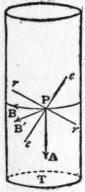
Fig. 26.
Maxwell has also given an explanation of the converse effect, namely, the production of longitudinal magnetization by twisting a wire when circularly magnetized by a current passing through it. When the wire is free from twist, the magnetization at any point P is in the tangential direction PB (see fig. 26). Suppose the wire to be fixed at the top and twisted at the bottom in the direction of the arrow-head T; then the element of the wire at P will be stretched in the direction Pe and compressed in the direction Pr. But tension and compression produce opposite changes in the magnetic susceptibility; if the metal is iron and its magnetization is below the Villari critical point, its susceptibility will be greater along Pe than along Pr; the direction of the magnetization therefore tends to approach Pe and to recede from Pr, changing, in consequence of the twist, from PB to some such direction as PB′, which has a vertical component downwards; hence the lower and upper ends will respectively acquire north and south polarity, which will disappear when the wire is untwisted. This effect has never been actually reversed in iron, probably, as suggested by Ewing, because the strongest practicable circular fields fail to raise the components of the magnetization along Pe and Pr up to the Villari critical value. Nagaoka and Honda have approached very closely to a reversal, and consider that it would occur if a sufficiently strong current could be applied without undue heating.
One other effect of torsion remains to be noticed. If a longitudinally magnetized wire is twisted, circular magnetization is developed; this is evidenced by the transient electromotive force induced in the iron, generating a current which will deflect a galvanometer connected with the two ends of the wire. The explanation given of the last described phenomenon will with the necessary modification apply also to this; it is a consequence of the aeolotropy produced by the twist. There are then three remarkable effects of torsion: