VOLUME XVII SLICE IV Magnetite to Malt
Reading edition
Articles in This Slice
MAGNETITE MAJOR, JOHN
MAGNETOGRAPH MAJOR
MAGNETOMETER MAJORCA
MAGNETO-OPTICS MAJORIAN
MAGNOLIA MAJORITY
MAGNUS, HEINRICH GUSTAV MAJUBA
MAGNY, CLAUDE DRIGON MAKALAKA
MAGO MAKARAKA
MAGPIE MAKART, HANS
MAGWE MAKING-UP PRICE
MAGYARS MAKÓ
MAHABALESHWAR MAKRAN
MAHAFFY, JOHN PENTLAND MAKSOORA
MAHALLAT MALABAR
MAHAN, ALFRED THAYER MALABARI, BEHRAMJI
MAHANADI MALABON
MAHANOY CITY MALACCA
MAHAR MALACHI
MAHARAJPUR MALACHITE
MAHĀVAṂSA MALACHOWSKI, STANISLAW
MAHAYANA MALACHY, ST
MAHDI MALACOSTRACA
MAHDIA MALAGA (province of Spain)
MAHÉ MALAGA (city of Spain)
MAHESHWAR MALAKAND PASS
MAHI MALALAS, JOHN
MAHI KANTHA MALAN, SOLOMON CAESAR
MAHMUD I. MÄLAR
MAHMUD II. MALARIA
MAHMUD NEDIM PASHA MALATIA
MAHMUD OF GHAZNI MALAYALAM
MAHOBA MALAY ARCHIPELAGO
MAHOGANY MALĀIR
MAHOMET MALAY PENINSULA
MAHOMMED AHMED IBN SEYYID ABDULLAH MALAYS
MAHOMMEDAN INSTITUTIONS MALAY STATES (British)
MAHOMMEDAN LAW MALAY STATES (Siamese)
MAHOMMEDAN RELIGION MALCHIN
MAHONY, FRANCIS SYLVESTER MALCOLM
MAHOUT MALCOLM, SIR JOHN
MAHRATTAS MALDA
MAHSEER MALDEN
MAI, ANGELO MALDIVE ISLANDS
MAIA MALDON
MAIDA MALEBRANCHE, NICOLAS
MAIDAN MALER KOTLA
MAIDEN MALESHERBES, CHRÉTIEN GUILLAUME DE LAMOIGNON DE
MAIDENHAIR MALET, LUCAS
MAIDENHEAD MALHERBE, FRANÇOIS DE
MAID MARIAN MALIBRAN, MARIE FÉLICITÉ
MAIDSTONE MALIC ACID
MAIHAR MALIGNANT
MAIL MALIK IBN ANAS
MAILLY, LOUISE JULIE MALINES
MAIMANA MALLANWAN
MAIMAND MALLARMÉ, FRANÇOIS RENÉ AUGUSTE
MAIMBOURG, LOUIS MALLARMÉ, STÉPHANE
MAIMING MALLECO
MAIMON, SALOMON MALLEMUCK
MAIMONIDES MALLESON, GEORGE BRUCE
MAIN (river of Germany) MALLET, DAVID
MAIN (power or strength) MALLET, PAUL HENRI
MAINA and MAINOTES MALLET, ROBERT
MAINE, ANNE LOUISE BÉNÉDICTE DE BOURBON MALLET DU PAN, JACQUES
MAINE, SIR HENRY JAMES SUMNER MALLING, EAST and WEST
MAINE (French province) MALLOCK, WILLIAM HURRELL
MAINE (U.S. state) MALLOW (town of Ireland)
MAINE DE BIRAN, FRANÇOIS-PIERRE-GONTHIER MALLOW (botanical genus)
MAINE-ET-LOIRE MALMEDY
MAINPURI MALMESBURY, JAMES HARRIS
MAINTENANCE MALMESBURY, JAMES HOWARD HARRIS
MAINTENON, FRANÇOISE D’AUBIGNÉ MALMESBURY
MAINZ MALMÖ
MAIRET, JEAN DE MALMSEY
MAISTRE, JOSEPH DE MALOCELLO, LANCILOTO
MAISTRE, XAVIER DE MALOLOS
MAITLAND, EDWARD MALONE, EDMOND
MAITLAND, FREDERIC WILLIAM MALONE
MAITLAND, SIR RICHARD MALONIC ACID
MAITLAND, WILLIAM MALORY, SIR THOMAS
MAITLAND, EAST and WEST MALOT, HECTOR HENRI
MAITREYA MALOU, JULES ÉDOUARD XAVIER
MAIWAND MALOUET, PIERRE VICTOR
MAIZE MALPIGHI, MARCELLO
MAJESTY MALPLAQUET
MAJLÁTH, JÁNOS MALSTATT-BURBACH
MAJOLICA MALT

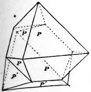
Fig. 1.
MAGNETITE, a mineral forming the natural magnet (see Magnetism), and important also as an iron-ore. It is an iron-black, opaque mineral, with metallic lustre; hardness about 6, sp. gr. 4.9 to 5.2. When scratched, it yields a black streak. It is an oxide of iron having the formula Fe3O4, corresponding with 72.4% of metal, whence its great value as an ore. It may be regarded as a ferroso-ferric oxide, FeO·Fe2O3, or as iron ferrate, Fe″Fe2″′O4. Titanium is often present, and occasionally the mineral contains magnesium, nickel, &c. It is always strongly magnetic. Magnetite crystallizes in the cubic system, usually in octahedra, less commonly in rhombic dodecahedra, and not infrequently in twins of the “spinel type” (fig. 1). The rhombic faces of the dodecahedron are often striated parallel to the longer diagonal. There is no distinct cleavage, but imperfect parting may be obtained along octahedral planes.
Magnetite is a mineral of wide distribution, occurring as grains in many massive and volcanic rocks, like granite, diorite and dolerite. It appears to have crystallized from the magma at a very early period of consolidation. Its presence contributes to the dark colour of many basalts and other basic rocks, and may cause them to disturb the compass. Large ore-bodies of granular and compact magnetite occur as beds and lenticular masses in Archean gneiss and crystalline schists, in various parts of Norway, Sweden, Finland and the Urals; as also in the states of New York, New Jersey, Pennsylvania and Michigan, as well as in Canada. In some cases it appears to have segregated from a basic eruptive magma, and in other cases to have resulted from metamorphic action. Certain deposits appear to have been formed, directly or indirectly, by wet processes. Iron rust sometimes contains magnetite. An interesting deposit of oolitic magnetic ore occurs in the Dogger (Inferior Oolite) of Rosedale Abbey, in Yorkshire; and a somewhat similar pisolitic ore, of Jurassic age, is known on the continent as chamoisite, having been named from Chamoison (or Chamoson) in the Valais, Switzerland. Grains of magnetite occur in serpentine, as an alteration-product of the olivine. In emery, magnetite in a granular form is largely associated with the corundum; and in certain kinds of mica magnetite occurs as thin dendritic enclosures. Haematite is sometimes magnetic, and A. Liversidge has shown that magnetite is probably present. By deoxidation, haematite may be converted into magnetite, as proved by certain pseudomorphs; but on the other hand magnetite is sometimes altered to haematite. On weathering, magnetite commonly passes into limonite, the ferrous oxide having probably been removed by carbonated waters. Closely related to magnetite is the rare volcanic mineral from Vesuvius, called magnoferrite, or magnesioferrite, with the formula MgFe2O4; and with this may be mentioned a mineral from Jakobsberg, in Vermland, Sweden, called jakobsite, containing MnFe2O4.
(F. W. R.*)
MAGNETOGRAPH, an instrument for continuously recording the values of the magnetic elements, the three universally chosen being the declination, the horizontal component and the vertical component (see Terrestrial Magnetism). In each case the magnetograph only records the variation of the element, the absolute values being determined by making observations in the neighbourhood with the unifilar magnetometer (q.v.) and inclinometer (q.v.).
Declination.—The changes in declination are obtained by means of a magnet which is suspended by a long fibre and carries a mirror, immediately below which a fixed mirror is attached to the base of the instrument. Both mirrors are usually concave; if plane, a concave lens is placed immediately before them. Light passing through a vertical slit falls upon the mirrors, from which it is reflected, and two images of the slit are produced, one by the movable mirror attached to the magnet and the other by the fixed mirror. These images would be short lines of light; but a piano-cylindrical lens is placed with its axis horizontal just in front of the recording surface. In this way a spot of light is obtained from each mirror. The recording surface is a sheet of photographic paper wrapped round a drum which is rotated at a constant speed by clockwork about a horizontal axis. The light reflected from the fixed mirror traces a straight line on the paper, serving as a base line from which the variations in declination are measured. As the declination changes the spot of light reflected from the magnet mirror moves parallel to the axis of the recording drum, and hence the distance between the line traced by this spot and the base line gives, for any instant, on an arbitrary scale the difference between the declination and a constant angle, namely, the declination corresponding to the base line. The value of this constant angle is obtained by comparing the record with the value for the declination as measured with a magnetometer. The value in terms of arc of the scale of the record can be obtained by measuring the distance between the magnet mirror and the recording drum, and in most observations it is such that a millimetre on the record represents one minute of arc. The time scale ordinarily employed is 15 mm. per hour, but in modern instruments provision is generally made for the time scale to be increased at will to 180 mm. per hour, so that the more rapid variations of the declination can be followed. The advantages of using small magnets, so that their moment of inertia may be small and hence they may be able to respond to rapid changes in the earth’s field, were first insisted upon by E. Mascart,1 while M. Eschenhagen2 first designed a set of magnetographs in which this idea of small moment of inertia was carried to its useful limit, the magnets only weighing 1.5 gram each, and the suspension consisting of a very fine quartz fibre.
Horizontal Force.—The variation of the horizontal force is obtained by the motion of a magnet which is carried either by a bifilar suspension or by a fairly stiff metal wire or quartz fibre. The upper end of the suspension is turned till the axis of the magnet is at right angles to the magnetic meridian. In this position the magnet is in equilibrium under the action of the torsion of the suspension and the couple exerted by the horizontal component, H, of the earth’s field, this couple depending on the product of H into the magnetic moment, M, of the magnet. Hence if H varies the magnet will rotate in such a way that the couple due to torsion is equal to the new value of H multiplied by M. Since the movements of the magnet are always small, the rotation of the magnet is proportional to the change in H, so long as M and the couple, θ, corresponding to unit twist of the suspension system remain constant. When the temperature changes, however, both M and θ in general change. With rise of temperature M decreases, and this alone will produce the same effect as would a decrease in H. To allow for this effect of temperature a compensating system of metal bars is attached to the upper end of the bifilar suspension, so arranged that with rise of temperature the fibres are brought nearer together and hence the value of θ decreases. Since such a decrease in θ would by itself cause the magnet to turn in the same direction as if H had increased, it is possible in a great measure to neutralize the effects of temperature on the reading of the instrument. In the case of the unifilar suspension, the provision of a temperature compensation is not so easy, so that what is generally done is to protect the instrument from temperature variation as much as possible and then to correct the indications so as to allow for the residual changes, a continuous record of the temperature being kept by a recording thermograph attached to the instrument. In the Eschenhagen pattern instrument, in which a single quartz fibre is used for the suspension, two magnets are placed in the vicinity of the suspended magnet and are so arranged that their field partly neutralizes the earth’s field; thus the torsion required to hold the magnet with its axis perpendicular to the earth’s field is reduced, and the arrangement permits of the sensitiveness being altered by changing the position of the deflecting magnets. Further, by suitably choosing the positions of the deflectors and the coefficient of torsion of the fibre, it is possible to make the temperature coefficient vanish. (See Adolf Schmidt, Zeits. für Instrumentenkunde, 1907, 27, 145.) The method of recording the variations in H is exactly the same as that adopted in the case of the declination, and the sensitiveness generally adopted is such that 1 mm. on the record represents a change in H of .00005 C.G.S., the time scale being the same as that employed in the case of the declination.
Vertical Component.—To record the variations of the vertical component use is made of a magnet mounted on knife edges so that it can turn freely about a horizontal axis at right angles to its length (H. Lloyd, Proc. Roy. Irish Acad., 1839, 1, 334). The magnet is so weighted that its axis is approximately horizontal, and any change in the inclination of the axis is observed by means of an attached mirror, a second mirror fixed to the stand serving to give a base line for the records, which are obtained in the same way as in the case of the declination. The magnet is in equilibrium under the influence of the couple VM due to the vertical component V, and the couple due to the fact that the centre of gravity is slightly on one side of the knife-edge. Hence when, say, V decreases the couple VM decreases, and hence the north end of the balanced magnet rises, and vice versa. The chief difficulty with this form of instrument is that it is very sensitive to changes of temperature, for such changes not only alter M but also in general cause the centre of gravity of the system to be displaced with reference to the knife-edge. To reduce these effects the magnet is fitted with compensating bars, generally of zinc, so adjusted by trial that as far as possible they neutralize the effect of changes of temperature. In the Eschenhagen form of vertical force balance two deflecting magnets are used to partly neutralize the vertical component, so that the centre of gravity is almost exactly over the support. By varying the positions of these deflecting magnets it is possible to compensate for the effects of changes of temperature (A. Schmidt, loc. cit.). In order to eliminate the irregularity which is apt to be introduced by dust, &c., interfering with the working of the knife-edge, W. Watson (Phil. Mag., 1904 [6], 7, 393) designed a form of vertical force balance in which the magnet with its mirror is attached to the mid point of a horizontal stretched quartz fibre. The temperature compensation is obtained by attaching a small weight to the magnet, and then bringing it back to the horizontal position by twisting the fibre.
The scale values of the records given by the horizontal and vertical force magnetographs are determined by deflecting the respective needles, either by means of a magnet placed at a known distance or by passing an electric current through circular coils of large diameter surrounding the instruments.
The width of the photographic sheet which receives the spot of light reflected from the mirrors in the above instruments is generally so great that in the case of ordinary changes the curve does not go off the paper. Occasionally, however, during a disturbance such is not the case, and hence a portion of the trace would be lost. To overcome this difficulty Eschenhagen in his earlier type of instruments attached to each magnet two mirrors, their planes being inclined at a small angle so that when the spot reflected from one mirror goes off the paper, that corresponding to the other comes on. In the later pattern a third mirror is added of which the plane is inclined at about 30° to the horizontal. The light from the slit is reflected on to this mirror by an inclined fixed mirror, and after reflection at the movable mirror is again reflected at the fixed mirror and so reaches the recording drum. By this arrangement the angular rotation of the reflected beam is less than that of the magnet, and hence the spot of light reflected from this mirror yields a trace on a much smaller scale than that given by the ordinary mirror and serves to give a complete record of even the most energetic disturbance.
See also Balfour Stewart, Report of the British Association, Aberdeen, 1859, 200, a description of the type of instrument used in the older observatories; E. Mascart, Traité de magnétisme terrestre, p. 191; W. Watson, Terrestrial Magnetism, 1901, 6, 187, describing magnetographs used in India; M. Eschenhagen, Verhandlungen der deutschen physikalischen Gesellschaft, 1899, 1, 147; Terrestrial Magnetism, 1900, 5, 59; and 1901, 6, 59; Zeits. für Instrumentenkunde, 1907, 27, 137; W. G. Cady, Terrestrial Magnetism, 1904, 9, 69, describing a declination magnetograph in which the record is obtained by means of a pen acting on a moving strip of paper, so that the curve can be consulted at all times to see whether a disturbance is in progress.
The effects of temperature being so marked on the readings of the horizontal and vertical force magnetographs, it is usual to place the instruments either in an underground room or in a room which, by means of double walls and similar devices, is protected as much as possible from temperature changes. For descriptions of the arrangements adopted in some observatories see the following: U.S. observatories, Terrestrial Magnetism, 1903, 8, 11; Utrecht, Terrestrial Magnetism, 1900, 5, 49; St Maur, Terrestrial Magnetism, 1898, 3, 1; Potsdam, Veröffentlichungen des k. preuss. meteorol. Instituts, “Ergebnisse der magnetischen Beobachtungen in Potsdam in den Jahren 1890 und 1891;” Pavlovsk, “Das Konstantinow’sche meteorologische und magnetische Observatorium in Pavlovsk,” Ausgabe der kaiserl. Akad. der Wissenschaften zu St Petersburg, 1895.
(W. Wn.)
1 Report British Association, Bristol, 1898, p. 741.
2 Verhandlungen der deutschen physikalischen Gesellschaft, 1899, 1, 147; or Terrestrial Magnetism, 1900, 5, 59.
MAGNETOMETER, a name, in its most general sense, for any instrument used to measure the strength of any magnetic field; it is, however, often used in the restricted sense of an instrument for measuring a particular magnetic field, namely, that due to the earth’s magnetism, and in this article the instruments used for measuring the value of the earth’s magnetic field will alone be considered.
The elements which are actually measured when determining the value of the earth’s field are usually the declination, the dip and the horizontal component (see Magnetism, Terrestrial). For the instruments and methods used in measuring the dip see Inclinometer. It remains to consider the measurement of the declination and the horizontal component, these two elements being generally measured with the same instrument, which is called a unifilar magnetometer.
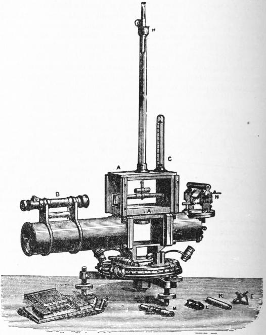
Fig. 1.—Unifilar Magnetometer, arranged to indicate declination.
Measurement of Declination.—The measurement of the declination involves two separate observations, namely, the determination of (a) the magnetic meridian and (b) the geographical meridian, the angle between the two being the declination. In order to determine the magnetic meridian the orientation of the magnetic axis of a freely suspended magnet is observed; while, in the absence of a distant mark of which the azimuth is known, the geographical meridian is obtained from observations of the transit of the sun or a star. The geometrical axis of the magnet is sometimes defined by means of a mirror rigidly attached to the magnet and having the normal to the mirror as nearly as may be parallel to the magnetic axis. This arrangement is not very convenient, as it is difficult to protect the mirror from accidental displacement, so that the angle between the geometrical and magnetic axes may vary. For this reason the end of the magnet is sometimes polished and acts as the mirror, in which case no displacement of the reflecting surface with reference to the magnet is possible. A different arrangement, used in the instrument described below, consists in having the magnet hollow, with a small scale engraved on glass firmly attached at one end, while to the other end is attached a lens, so chosen that the scale is at its principal focus. In this case the geometrical axis is the line joining the central division of the scale to the optical centre of the lens. The position of the magnet is observed by means of a small telescope, and since the scale is at the principal focus of the lens, the scale will be in focus when the telescope is adjusted to observe a distant object. Thus no alteration in the focus of the telescope is necessary whether we are observing the magnet, a distant fixed mark, or the sun.
The Kew Observatory pattern unifilar magnetometer is shown in figs. 1 and 2. The magnet consists of a hollow steel cylinder fitted with a scale and lens as described above, and is suspended by a long thread of unspun silk, which is attached at the upper end to the torsion head H. The magnet is protected from draughts by the box A, which is closed at the sides by two shutters when an observation is being taken. The telescope B serves to observe the scale attached to the magnet when determining the magnetic meridian, and to observe the sun or star when determining the geographical meridian.
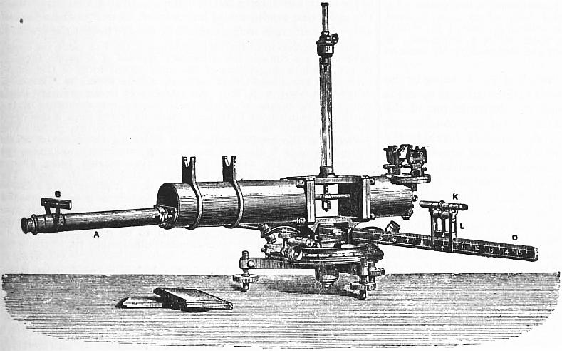
Fig. 2.—Unifilar Magnetometer, arranged to show deflexion.
When making a determination of declination a brass plummet having the same weight as the magnet is first suspended in its place, and the torsion of the fibre is taken out. The magnet having been attached, the instrument is rotated about its vertical axis till the centre division of the scale appears to coincide with the vertical cross-wire of the telescope. The two verniers on the azimuth circle having been read, the magnet is then inverted, i.e. turned through 180° about its axis, and the setting is repeated. A second setting with the magnet inverted is generally made, and then another setting with the magnet in its original position. The mean of all the readings of the verniers gives the reading on the azimuth circle corresponding to the magnetic meridian. To obtain the geographical meridian the box A is removed, and an image of the sun or a star is reflected into the telescope B by means of a small transit mirror N. This mirror can rotate about a horizontal axis which is at right angles to the line of collimation of the telescope, and is parallel to the surface of the mirror. The time of transit of the sun or star across the vertical wire of the telescope having been observed by means of a chronometer of which the error is known, it is possible to calculate the azimuth of the sun or star, if the latitude and longitude of the place of observation are given. Hence if the readings of the verniers on the azimuth circle are made when the transit is observed we can deduce the reading corresponding to the geographical meridian.
The above method of determining the geographical meridian has the serious objection that it is necessary to know the error of the chronometer with very considerable accuracy, a matter of some difficulty when observing at any distance from a fixed observatory. If, however, a theodolite, fitted with a telescope which can rotate about a horizontal axis and having an altitude circle, is employed, so that when observing a transit the altitude of the sun or star can be read off, then the time need only be known to within a minute or so. Hence in more recent patterns of magnetometer it is usual to do away with the transit mirror method of observing and either to use a separate theodolite to observe the azimuth of some distant object, which will then act as a fixed mark when making the declination observations, or to attach to the magnetometer an altitude telescope and circle for use when determining the geographical meridian.
The chief uncertainty in declination observations, at any rate at a fixed observatory, lies in the variable torsion of the silk suspension, as it is found that, although the fibre may be entirely freed from torsion before beginning the declination observations, yet at the conclusion of these observations a considerable amount of torsion may have appeared. Soaking the fibre with glycerine, so that the moisture it absorbs does not change so much with the hygrometric state of the air, is of some advantage, but does not entirely remove the difficulty. For this reason some observers use a thin strip of phosphor bronze to suspend the magnet, considering that the absence of a variable torsion more than compensates for the increased difficulty in handling the more fragile metallic suspension.
Measurement of the Horizontal Component of the Earth’s Field.—The method of measuring the horizontal component which is almost exclusively used, both in fixed observatories and in the field, consists in observing the period of a freely suspended magnet, and then obtaining the angle through which an auxiliary suspended magnet is deflected by the magnet used in the first part of the experiment. By the vibration experiment we obtain the value of the product of the magnetic moment (M) of the magnet into the horizontal component (H), while by the deflexion experiment we can deduce the value of the ratio of M to H, and hence the two combined give both M and H.
In the case of the Kew pattern unifilar the same magnet that is used for the declination is usually employed for determining H, and for the purposes of the vibration experiment it is mounted as for the observation of the magnetic meridian. The time of vibration is obtained by means of a chronometer, using the eye-and-ear method. The temperature of the magnet must also be observed, for which purpose a thermometer C (fig. 1) is attached to the box A.
When making the deflection experiment the magnetometer is arranged as shown in fig. 2. The auxiliary magnet has a plane mirror attached, the plane of which is at right angles to the axis of the magnet. An image of the ivory scale B is observed after reflection in the magnet mirror by the telescope A. The magnet K used in the vibration experiment is supported on a carriage L which can slide along the graduated bar D. The axis of the magnet is horizontal and at the same level as the mirror magnet, while when the central division of the scale B appears to coincide with the vertical cross-wire of the telescope the axes of the two magnets are at right angles. During the experiment the mirror magnet is protected from draughts by two wooden doors which slide in grooves. What is known as the method of sines is used, for since the axes of the two magnets are always at right angles when the mirror magnet is in its zero position, the ratio M/H is proportional to the sine of the angle between the magnetic axis of the mirror magnet and the magnetic meridian. When conducting a deflexion experiment the deflecting magnet K is placed with its centre at 30 cm. from the mirror magnet and to the east of the latter, and the whole instrument is turned till the centre division of the scale B coincides with the cross-wire of the telescope, when the readings of the verniers on the azimuth circle are noted. The magnet K is then reversed in the support, and a new setting taken. The difference between the two sets of readings gives twice the angle which the magnetic axis of the mirror magnet makes with the magnetic meridian. In order to eliminate any error due to the zero of the scale D not being exactly below the mirror magnet, the support L is then removed to the west side of the instrument, and the settings are repeated. Further, to allow of a correction being applied for the finite length of the magnets the whole series of settings is repeated with the centre of the deflecting magnet at 40 cm. from the mirror magnet.
Omitting correction terms depending on the temperature and on the inductive effect of the earth’s magnetism on the moment of the deflecting magnet, if θ is the angle which the axis of the deflected magnet makes with the meridian when the centre of the deflecting magnet is at a distance r, then
r³H sin θ = 1 + P + Q + &c.,
2M r r²
in which P and Q are constants depending on the dimensions and magnetic states of the two magnets. The value of the constants P and Q can be obtained by making deflexion experiments at three distances. It is, however, possible by suitably choosing the proportions of the two magnets to cause either P or Q to be very small. Thus it is usual, if the magnets are of similar shape, to make the deflected magnet 0.467 of the length of the deflecting magnet, in which case Q is negligible, and thus by means of deflexion experiments at two distances the value of P can be obtained. (See C. Börgen, Terrestrial Magnetism, 1896, i. p. 176, and C. Chree, Phil. Mag., 1904 [6], 7, p. 113.)
In the case of the vibration experiment correction terms have to be introduced to allow for the temperature of the magnet, for the inductive effect of the earth’s field, which slightly increases the magnetic moment of the magnet, and for the torsion of the suspension fibre, as well as the rate of the chronometer. If the temperature of the magnet were always exactly the same in both the vibration and deflexion experiment, then no correction on account of the effect of temperature in the magnetic moment would be necessary in either experiment. The fact that the moment of inertia of the magnet varies with the temperature must, however, be taken into account. In the deflexion experiment, in addition to the induction correction, and that for the effect of temperature on the magnetic moment, a correction has to be applied for the effect of temperature on the length of the bar which supports the deflexion magnet.
See also Stewart and Gee, Practical Physics, vol. 2, containing a description of the Kew pattern unifilar magnetometer and detailed instructions for performing the experiments; C. Chree, Phil. Mag., 1901 (6), 2, p. 613, and Proc. Roy. Soc., 1899, 65, p. 375, containing a discussion of the errors to which the Kew unifilar instrument is subject; E. Mascart, Traité de magnétisme terrestre, containing a description of the instruments used in the French magnetic survey, which are interesting on account of their small size and consequent easy portability; H. E. D. Fraser, Terrestrial Magnetism, 1901, 6, p. 65, containing a description of a modified Kew pattern unifilar as used in the Indian survey; H. Wild, Mém. Acad. imp. sc. St Pétersbourg, 1896 (viii.), vol. 3, No. 7, containing a description of a most elaborate unifilar magnetometer with which it is claimed results can be obtained of a very high order of accuracy; K. Haufsmann, Zeits. für Instrumentenkunde, 1906, 26, p. 2, containing a description of a magnetometer for field use, designed by M. Eschenhagen, which has many advantages.
Measurements of the Magnetic Elements at Sea.—Owing to the fact that the proportion of the earth’s surface covered by sea is so much greater than the dry land, the determination of the magnetic elements on board ship is a matter of very considerable importance. The movements of a ship entirely preclude the employment of any instrument in which a magnet suspended by a fibre has any part, so that the unifilar is unsuited for such observations. In order to obtain the declination a pivoted magnet is used to obtain the magnetic meridian, the geographical meridian being obtained by observations on the sun or stars. A carefully made ship’s compass is usually employed, though in some cases the compass card, with its attached magnets, is made reversible, so that the inclination to the zero of the card of the magnetic axis of the system of magnets attached to the card can be eliminated by reversal. In the absence of such a reversible card the index correction must be determined by comparison with a unifilar magnetometer, simultaneous observations being made on shore, and these observations repeated as often as occasion permits. To determine the dip a Fox’s dip circle1 is used. This consists of an ordinary dip circle (see Inclinometer) in which the ends of the axle of the needle are pointed and rest in jewelled holes, so that the movements of the ship do not displace the needle. The instrument is, of course, supported on a gimballed table, while the ship during the observations is kept on a fixed course. To obtain the strength of the field the method usually adopted is that known as Lloyd’s method.2 To carry out a determination of the total force by this method the Fox dip circle has been slightly modified by E. W. Creak, and has been found to give satisfactory results on board ship. The circle is provided with two needles in addition to those used for determining the dip, one (a) an ordinary dip needle, and the other (b) a needle which has been loaded at one end by means of a small peg which fits into one of two symmetrically placed holes in the needle. The magnetism of these two needles is never reversed, and they are as much as possible protected from shock and from approach to other magnets, so that their magnetic state may remain as constant as possible. Attached to the cross-arm which carries the microscopes used to observe the ends of the dipping needle is a clamp, which will hold the needle b in such a way that its plane is parallel to the vertical circle and its axis is at right angles to the line joining the two microscopes. Hence, when the microscopes are adjusted so as to coincide with the points of the dipping needle a, the axes of the two needles must be at right angles. The needle a being suspended between the jewels, and the needle b being held in the clamp, the cross-arm carrying the reading microscopes and the needle b is rotated till the ends of the needle a coincide with the cross-wires of the microscopes. The verniers having been read, the cross-arm is rotated so as to deflect the needle a in the opposite direction, and a new setting is taken. Half the difference between the two readings gives the angle through which the needle a has been deflected under the action of the needle b. This angle depends on the ratio of the magnetic moment of the needle b to the total force of the earth’s field. It also involves, of course, the distance between the needles and the distribution of the magnetism of the needles; but this factor is determined by comparing the value given by the instrument, at a shore station, with that given by an ordinary magnetometer. Hence the above observation gives us a means of obtaining the ratio of the magnetic moment of the needle b to the value of the earth’s total force. The needle b is then substituted for a, there being now no needle in the clamp attached to the microscope arm, and the difference between the reading now obtained and the dip, together with the weight added to the needle, gives the product of the moment of the needle b into the earth’s total force. Hence, from the two observations the value of the earth’s total force can be deduced. In an actual observation the deflecting needle would be reversed, as well as the deflected one, while different weights would be used to deflect the needle b.
For a description of the method of using the Fox circle for observations at sea consult the Admiralty Manual of Scientific Inquiry, p. 116, while a description of the most recent form of the circle, known as the Lloyd-Creak pattern, will be found in Terrestrial Magnetism, 1901, 6, p. 119. An attachment to the ordinary ship’s compass, by means of which satisfactory measurements of the horizontal component have been made on board ship, is described by L. A. Bauer in Terrestrial Magnetism, 1906, 11, p. 78. The principle of the method consists in deflecting the compass needle by means of a horizontal magnet supported vertically over the compass card, the axis of the deflecting magnet being always perpendicular to the axis of the magnet attached to the card. The method is not strictly an absolute one, since it presupposes a knowledge of the magnetic moment of the deflecting magnet. In practice it is found that a magnet can be prepared which, when suitably protected from shock, &c., retains its magnetic moment sufficiently constant to enable observations of H to be made comparable in accuracy with that of the other elements obtained by the instruments ordinarily employed at sea.
(W. Wn.)
1 Annals of Electricity, 1839, 3, p. 288.
2 Humphrey Lloyd, Proc. Roy. Irish Acad., 1848, 4, p. 57.
MAGNETO-OPTICS. The first relation between magnetism and light was discovered by Faraday,1 who proved that the plane of polarization of a ray of light was rotated when the ray travelled through certain substances parallel to the lines of magnetic force. This power of rotating the plane of polarization in a magnetic field has been shown to be possessed by all refracting substances, whether they are in the solid, liquid or gaseous state. The rotation by gases was established independently by H. Becquerel,2 and Kundt and Röntgen,3 while Kundt4 found that films of the magnetic metals, iron, cobalt, nickel, thin enough to be transparent, produced enormous rotations, these being in iron and cobalt magnetized to saturation at the rate of 200,000° per cm. of thickness, and in nickel about 89,000°. The direction of rotation is not the same in all bodies. If we call the rotation positive when it is related to the direction of the magnetic force, like rotation and translation in a right-handed screw, or, what is equivalent, when it is in the direction of the electric currents which would produce a magnetic field in the same direction as that which produces the rotation, then most substances produce positive rotation. Among those that produce negative rotation are ferrous and ferric salts, ferricyanide of potassium, the salts of lanthanum, cerium and didymium, and chloride of titanium.5
The magnetic metals iron, nickel, cobalt, the salts of nickel and cobalt, and oxygen (the most magnetic gas) produce positive rotation.
For slightly magnetizable substances the amount of rotation in a space PQ is proportional to the difference between the magnetic potential at P and Q; or if θ is the rotation in PQ, ΩP, ΩQ, the magnetic potential at P and Q, then θ = R(ΩP − ΩQ), where R is a constant, called Verdet’s constant, which depends upon the refracting substance, the wave length of the light, and the temperature. The following are the values of R (when the rotation is expressed in circular measure) for the D line and a temperature of 18° C.:—
Substance. R × 105. Observer.
Carbon bisulphide 1.222 Lord Rayleigh6 and Köpsel.7
1.225 Rodger and Watson.8
Water .377 Arons.9
.3808 Rodger and Watson.8
Alcohol .330 Du Bois.10
Ether .315 Du Bois.10
Oxygen (at 1 atmosphere) .000179 Kundt and Röntgen (loc. cit.)
Faraday’s heavy glass 1.738
The variation of Verdet’s constant with temperature has been determined for carbon bisulphide and water by Rodger and Watson (loc. cit.). They find if Rt, R0 are the values of Verdet’s constant at t°C and 0°C. respectively, then for carbon bisulphide Rt = R0 (1 − .0016961), and for water Rt = R0 (1 − .0000305t − .00000305t²).
For the magnetic metals Kundt found that the rotation did not increase so rapidly as the magnetic force, but that as this force was increased the rotation reached a maximum value. This suggests that the rotation is proportional to the intensity of magnetization, and not to the magnetic force.
The amount of rotation in a given field depends greatly upon the wave length of the light; the shorter the wave length the greater the rotation, the rotation varying a little more rapidly than the inverse square of the wave length. Verdet11 has compared in the cases of carbon bisulphide and creosote the rotation given by the formula
θ = mcγ c² ( c − λ di )
λ² dλ
with those actually observed; in this formula θ is the angular rotation of the plane of polarization, m a constant depending on the medium, λ the wave length of the light in air, and i its index of refraction in the medium. Verdet found that, though the agreement is fair, the differences are greater than can be explained by errors of experiment.
Verdet12 has shown that the rotation of a salt solution is the sum of the rotations due to the salt and the solvent; thus, by mixing a salt which produces negative rotation with water which produces positive rotation, it is possible to get a solution which does not exhibit any rotation. Such solutions are not in general magnetically neutral. By mixing diamagnetic and paramagnetic substances we can get magnetically neutral solutions, which, however, produce a finite rotation of the plane of polarization. The relation of the magnetic rotation to chemical constitution has been studied in great detail by Perkin,13 Wachsmuth,14 Jahn15 and Schönrock.16
The rotation of the plane of polarization may conveniently be regarded as denoting that the velocity of propagation of circular-polarized light travelling along the lines of magnetic force depends upon the direction of rotation of the ray, the velocity when the rotation is related to the direction of the magnetic force, like rotation and translation on a right-handed screw being different from that for a left-handed rotation. A plane-polarized ray may be regarded as compounded of two oppositely circularly-polarized rays, and as these travel along the lines of magnetic force with different velocities, the one will gain or lose in phase on the other, so that when they are again compounded they will correspond to a plane-polarized ray, but in consequence of the change of phase the plane of polarization will not coincide with its original position.
Reflection from a Magnet.—Kerr17 in 1877 found that when plane-polarized light is incident on the pole of an electromagnet, polished so as to act like a mirror, the plane of polarization of the reflected light is rotated by the magnet. Further experiments on this phenomenon have been made by Righi,18 Kundt,19 Du Bois,20 Sissingh,21 Hall,22 Hurion,23 Kaz24 and Zeeman.25 The simplest case is when the incident plane-polarized light falls normally on the pole of an electromagnet. When the magnet is not excited the reflected ray is plane-polarized; when the magnet is excited the plane of polarization is rotated through a small angle, the direction of rotation being opposite to that of the currents exciting the pole. Righi found that the reflected light was slightly elliptically polarized, the axes of the ellipse being of very unequal magnitude. A piece of gold-leaf placed over the pole entirely stops the rotation, showing that it is not produced in the air near the pole. Rotation takes place from magnetized nickel and cobalt as well as from iron, and is in the same direction (Hall). Righi has shown that the rotation at reflection is greater for long waves than for short, whereas, as we have seen, the Faraday rotation is greater for short waves than for long. The rotation for different coloured light from iron, nickel, cobalt and magnetite has been measured by Du Bois; in magnetite the direction of rotation is opposite to that of the other metals. When the light is incident obliquely and not normally on the polished pole of an electromagnet, it is elliptically polarized after reflection, even when the plane of polarization is parallel or at right angles to the plane of incidence. According to Righi, the amount of rotation when the plane of polarization of the incident light is perpendicular to the plane of incidence reaches a maximum when the angle of incidence is between 44° and 68°, while when the light is polarized in the plane of incidence the rotation steadily decreases as the angle of incidence is increased. The rotation when the light is polarized in the plane of incidence is always less than when it is polarized at right angles to that plane, except when the incidence is normal, when the two rotations are of course equal.
Reflection from Tangentially Magnetized Iron.—In this case Kerr26 found: (1) When the plane of incidence is perpendicular to the lines of magnetic force, no rotation of the reflected light is produced by magnetization; (2) no rotation is produced when the light is incident normally; (3) when the incidence is oblique, the lines of magnetic force being in the plane of incidence, the reflected light is elliptically polarized after reflection, and the axes of the ellipse are not in and at right angles to the plane of incidence. When the light is polarized in the plane of incidence, the rotation is at all angles of incidence in the opposite direction to that of the currents which would produce a magnetic field of the same sign as the magnet. When the light is polarized at right angles to the plane of incidence, the rotation is in the same direction as these currents when the angle of incidence is between 0° and 75° according to Kerr, between 0° and 80° according to Kundt, and between 0° and 78° 54′ according to Righi. When the incidence is more oblique than this, the rotation of the plane of polarization is in the opposite direction to the electric currents which would produce a magnetic field of the same sign.
The theory of the phenomena just described has been dealt with by Airy,27 C. Neumann,28 Maxwell,29 Fitzgerald,30 Rowland,31 H. A. Lorentz,32 Voight,33 Ketteler,34 van Loghem,35 Potier,36 Basset,37 Goldhammer,38 Drude,39 J. J. Thomson,40 and Leatham;41 for a critical discussion of many of these theories we refer the reader to Larmor’s42 British Association Report. Most of these theories have proceeded on the plan of adding to the expression for the electromotive force terms indicating a force similar in character to that discovered by Hall (see Magnetism) in metallic conductors carrying a current in a magnetic field, i.e. an electromotive force at right angles to the plane containing the magnetic force and the electric current, and proportional to the sine of the angle between these vectors. The introduction of a term of this kind gives rotation of the plane of polarization by transmission through all refracting substance, and by reflection from magnetized metals, and shows a fair agreement between the theoretical and experimental results. The simplest way of treating the questions seems, however, to be to go to the equations which represent the propagation of a wave travelling through a medium containing ions. A moving ion in a magnetic field will be acted upon by a mechanical force which is at right angles to its direction of motion, and also to the magnetic force, and is equal per unit charge to the product of these two vectors and the sine of the angle between them. For the sake of brevity we will take the special case of a wave travelling parallel to the magnetic force in the direction of the axis of z.
Then supposing that all the ions are of the same kind, and that there are n of these each with mass m and charge e per unit volume, the equations representing the field are (see Electric Waves):—
K0 dX0 + 4πne dξ = dβ ;
dt dt dz
dX0 = dβ ;
dz dt
K0 dY0 + 4πne dη = − dα
dt dt dz
dY0 = − dα ;
dz dt
m d²ξ + R1 dξ + aξ = ( X0 + 4π neξ ) e + He dη
dt² dt 3 dt
m d²η + R1 dη + aη = ( Y0 + 4π neη ) e − He dξ ;
dt² dt 3 dt
where H is the external magnetic field, X0, Y0 the components of the part of the electric force in the wave not due to the charges on the atoms, α and β the components of the magnetic force, ξ and η the co-ordinates of an ion, R1 the coefficient of resistance to the motion of the ions, and α the force at unit distance tending to bring the ion back to its position of equilibrium, K0 the specific inductive capacity of a vacuum. If the variables are proportional to εl(pt−qz) we find by substitution that q is given by the equation
q² − K0p² − 4πne²p²P = ± 4πne³Hp³ ,
P² − H²e²p² P² − H²e²p²
where
P = (a − 4⁄3πne²) + R1ιp − mp²,
or, by neglecting R, P = m (s² − p²), where s is the period of the free ions. If, q1², q2² are the roots of this equation, then corresponding to q1 we have X0 = ιY0 and to q2 X0 = −ιY0. We thus get two oppositely circular-polarized rays travelling with the velocities p/q1 and p/q2 respectively. Hence if v1, v2 are these velocities, and v the velocity when there is no magnetic field, we obtain, if we neglect terms in H²,
1 = 1 + 4πne³Hp ,
v1² v² m² (s² − p²)²
1 = 1 − 4πne³Hp .
v2² v² m² (s² − p²)²
The rotation r of the plane of polarization per unit length
= ½p ( 1 − 1 ) = 2πne³Hp²v .
v1 v2 m² (s² − p²)²
Since 1/v² = K0 + 4πne²/m (s² − p²), we have if µ is the refractive index for light of frequency p, and v0 the velocity of light in vacuo.
µ² − 1 = 4πne²v0² / m (s² − p²).
(1)
So that we may put
r = (µ² − 1)² p²H / sπµnev0³.
(2)
Becquerel (Comptes rendus, 125, p. 683) gives for r the expression
½ e H dµ ,
m v0 dλ
where λ is the wave length. This is equivalent to (2) if µ is given by (1). He has shown that this expression is in good agreement with experiment. The sign of r depends on the sign of e, hence the rotation due to negative ions would be opposite to that for positive. For the great majority of substances the direction of rotation is that corresponding to the negation ion. We see from the equations that the rotation is very large for such a value of p as makes P = 0; this value corresponds to a free period of the ions, so that the rotation ought to be very large in the neighbourhood of an absorption band. This has been verified for sodium vapour by Macaluso and Corbino.43
If plane-polarized light falls normally on a plane face of the medium containing the ions, then if the electric force in the incident wave is parallel to x and is equal to the real part of Aεl(pt−qz), if the reflected beam in which the electric force is parallel to x is represented by Bεl(pt+qz) and the reflected beam in which the electric force is parallel to the axis of y by Cεl(pt+qz), then the conditions that the magnetic force parallel to the surface is continuous, and that the electric forces parallel to the surface in the air are continuous with Y0, X0 in the medium, give
A = B = ιC
(q + q1) (q + q2) (q² − q1q2) q (q2 − q1)
or approximately, since q1 and q2 are nearly equal,
ιC = q (q2 − q1) = (µ² − 1) pH .
B q² − q1² 4πµneV0²
Thus in transparent bodies for which µ is real, C and B differ in phase by π/2, and the reflected light is elliptically polarized, the major axis of the ellipse being in the plane of polarization of the incident light, so that in this case there is no rotation, but only elliptic polarization; when there is strong absorption so that µ contains an imaginary term, C/B will contain a real part so that the reflected light will be elliptically polarized, but the major axis is no longer in the plane of polarization of the incident light; we should thus have a rotation of the plane of polarization superposed on the elliptic polarization.
Zeeman’s Effect.—Faraday, after discovering the effect of a magnetic field on the plane of polarization of light, made numerous experiments to see if such a field influenced the nature of the light emitted by a luminous body, but without success. In 1885 Fievez,44 a Belgian physicist, noticed that the spectrum of a sodium flame was changed slightly in appearance by a magnetic field; but his observation does not seem to have attracted much attention, and was probably ascribed to secondary effects. In 1896 Zeeman45 saw a distinct broadening of the lines of lithium and sodium when the flames containing salts of these metals were between the poles of a powerful electromagnet; following up this observation, he obtained some exceedingly remarkable and interesting results, of which those observed with the blue-green cadmium line may be taken as typical. He found that in a strong magnetic field, when the lines of force are parallel to the direction of propagation of the light, the line is split up into a doublet, the constituents of which are on opposite sides of the undisturbed position of the line, and that the light in the constituents of this doublet is circularly polarized, the rotation in the two lines being in opposite directions. When the magnetic force is at right angles to the direction of propagation of the light, the line is resolved into a triplet, of which the middle line occupies the same position as the undisturbed line; all the constituents of this triplet are plane-polarized, the plane of polarization of the middle line being at right angles to the magnetic force, while the outside lines are polarized on a plane parallel to the lines of magnetic force. A great deal of light is thrown on this phenomenon by the following considerations due to H. A. Lorentz.46
Let us consider an ion attracted to a centre of force by a force proportional to the distance, and acted on by a magnetic force parallel to the axis of z: then if m is the mass of the particle and e its charge, the equations of motion are
m d²x + αx = − He dy ;
dt² dt
m d²y + αy = He dx ;
dt² dt
m d²z + ax = 0.
dt²
The solution of these equations is
x = A cos (p1t + β) + B cos (p2t + β1)
y = A sin (p1t + β) − B sin (p2t + β1)
z = C cos (pt + γ)
where
α − mp1² = − Hep1
α − mp2² = Hep2
p² = α / m,
or approximately
p1 = p + ½ He , p2 = p − ½ He .
m m
Thus the motion of the ion on the xy plane may be regarded as made up of two circular motions in opposite directions described with frequencies p1 and p2 respectively, while the motion along z has the period p, which is the frequency for all the vibrations when H = 0. Now suppose that the cadmium line is due to the motion of such an ion; then if the magnetic force is along the direction of propagation, the vibration in this direction has its period unaltered, but since the direction of vibration is perpendicular to the wave front, it does not give rise to light. Thus we are left with the two circular motions in the wave front with frequencies p1 and p2 giving the circularly polarized constituents of the doublet. Now suppose the magnetic force is at right angles to the direction of propagation of the light; then the vibration parallel to the magnetic force being in the wave front produces luminous effects and gives rise to a plane-polarized ray of undisturbed period (the middle line of the triplet), the plane of polarization being at right angles to the magnetic force. The components in the wave-front of the circular orbits at right angles to the magnetic force will be rectilinear motions of frequency p1 and p2 at right angles to the magnetic force—so that they will produce plane-polarized light, the plane of polarization being parallel to the magnetic force; these are the outer lines of the triplet.
If Zeeman’s observations are interpreted from this point of view, the directions of rotation of the circularly-polarized light in the doublet observed along the lines of magnetic force show that the ions which produce the luminous vibrations are negatively electrified, while the measurement of the charge of frequency due to the magnetic field shows that e/m is of the order 107. This result is of great interest, as this is the order of the value of e/m in the negatively electrified particles which constitute the Cathode Rays (see Conduction, Electric III. Through Gases). Thus we infer that the “cathode particles” are found in bodies, even where not subject to the action of intense electrical fields, and are in fact an ordinary constituent of the molecule. Similar particles are found near an incandescent wire, and also near a metal plate illuminated by ultra-violet light. The value of e/m deduced from the Zeeman effect ranges from 107 to 3.4 × 10⁷, the value of e/m for the particle in the cathode rays is 1.7 × 10⁷. The majority of the determinations of e/m from the Zeeman effect give numbers larger than this, the maximum being about twice this value.
A more extended study of the behaviour of the spectroscopic lines has afforded examples in which the effects produced by a magnet are more complicated than those we have described, indeed the simple cases are much less numerous than the more complex. Thus Preston47 and Cornu48 have shown that under the action of a transverse magnetic field one of the D lines splits up into four, and the other into six lines; Preston has given many other examples of these quartets and sextets, and has shown that the change in the frequency, which, according to the simple theory indicated, should be the same for all lines, actually varies considerably from one line to another, many lines showing no appreciable displacement. The splitting up of a single line into a quartet or sextet indicates, from the point of view of the ion theory, that the line must have its origin in a system consisting of more than one ion. A single ion having only three degrees of freedom can only have three periods. When there is no magnetic force acting on the ion these periods are equal, but though under the action of a magnetic force they are separated, their number cannot be increased. When therefore we get four or more lines, the inference is that the system giving the lines must have at least four degrees of freedom, and therefore must consist of more than one ion. The theory of a system of ions mutually influencing each other shows, as we should expect, that the effects are more complex than in the case of a single ion, and that the change in the frequency is not necessarily the same for all systems (see J. J. Thomson, Proc. Camb. Phil. Soc. 13, p. 39). Preston49 and Runge and Paschen have proved that, in some cases at any rate, the change in the frequency of the different lines is of such a character that they can be grouped into series such that each line in the series has the same change in frequency for the same magnetic force, and, moreover, that homologous lines in the spectra of different metals belonging to the same group have the same change in frequency.
A very remarkable case of the Zeeman effect has been discovered by H. Becquerel and Deslandres (Comptes rendus, 127, p. 18). They found lines in iron when the most deflected components are those polarized in the plane at right angles to the magnetic force. On the simple theory the light polarized in this way is not affected. Thus the behaviour of the spectrum in the magnetic field promises to throw great light on the nature of radiation, and perhaps on the constitution of the elements. The study of these effects has been greatly facilitated by the invention by Michelson50 of the echelon spectroscope.
There are some interesting phenomena connected with the Zeeman effect which are more easily observed than the effect itself. Thus Cotton51 found that if we have two Bunsen flames, A and B, coloured by the same salt, the absorption of the light of one by the other is diminished if either is placed between the poles of a magnet: this is at once explained by the Zeeman effect, for the times of vibration of the molecules of the flame in the magnetic field are not the same as those of the other flame, and thus the absorption is diminished. Similar considerations explain the phenomenon observed by Egoroff and Georgiewsky,52 that the light emitted from a flame in a transverse field is partially polarized in a plane parallel to the magnetic force; and also Righi’s53 observation that if a sodium flame is placed in a longitudinal field between two crossed Nicols, and a ray of white light sent through one of the Nicols, then through the flame, and then through the second Nicol, the amount of light passing through the second Nicol is greater when the field is on than when it is off. Voight and Wiechert (Wied. Ann. 67, p. 345) detected the double refraction produced when light travels through a substance exposed to a magnetic field at right angles to the path of the light; this result had been predicted by Voight from theoretical considerations. Jean Becquerel has made some very interesting experiments on the effect of a magnetic field on the fine absorption bands produced by xenotime, a phosphate of yttrium and erbium, and tysonite, a fluoride of cerium, lanthanum and didymium, and has obtained effects which he ascribes to the presence of positive electrons. A very complete account of magneto- and electro-optics is contained in Voight’s Magneto- and Elektro-optik.
1 Experimental Researches, Series 19.
2 Comptes rendus, 88, p. 709.
3 Wied. Ann. 6, p. 332; 8, p. 278; 10, p. 257.
4 Wied. Ann. 23, p. 228; 27, p. 191.
5 Wied. Ann. 31, p. 941.
6 Phil. Trans., A. 1885, Pt. 11, p. 343.
7 Wied. Ann. 26, p. 456.
8 Phil. Trans., A. 1895, Pt. 17, p. 621.
9 Wied. Ann. 24, p. 161.
10 Wied. Ann. 31, p. 970.
11 Comptes rendus, 57, p. 670.
12 Comptes rendus, 43, p. 529; 44, p. 1209.
13 Journ. Chem. Soc. 1884, p. 421; 1886, p. 177; 1887, pp. 362 and 808; 1888, p. 561; 1889, pp. 680 and 750; 1891, p. 981; 1892, p. 800; 1893, pp. 75, 99 and 488.
14 Wied. Ann. 44, p. 377.
15 Wied. Ann. 43, p. 280.
16 Zeitschrift f. physikal. Chem. 11, p. 753.
17 Phil. Mag. [5] 3, p. 321.
18 Ann. de chim. et de phys. [6] 4, p. 433; 9, p. 65; 10, p. 200.
19 Wied. Ann. 23, p. 228; 27, p. 191.
20 Wied. Ann. 39, p. 25.
21 Wied. Ann. 42, p. 115.
22 Phil. Mag. [5] 12, p. 171.
23 Journ. de Phys. 1884, p. 360.
24 Beiblätter zu Wied. Ann. 1885, p. 275.
25 Messungen über d. Kerr’sche Erscheinung. Inaugural Dissert. Leiden, 1893.
26 Phil. Mag. [5] 5, p. 161.
27 Phil. Mag. [3] 28, p. 469.
28 Die Magn. Drehung d. Polarisationsebene des Lichts, Halle, 1863.
29 Electricity and Magnetism, chap. xxi.
30 Phil. Trans. 1880 (2), p. 691.
31 Phil. Mag. (5) 11, p. 254, 1881.
32 Arch. Néerl. 19, p. 123.
33 Wied. Ann. 23, p. 493; 67, p. 345.
34 Wied. Ann. 24, p. 119.
35 Wied. Beiblätter, 8, p. 869.
36 Comptes rendus, 108, p. 510.
37 Phil. Trans. 182, A. p. 371, 1892; Physical Optics, p. 393.
38 Wied. Ann. 46, p. 71; 47, p. 345; 48, p. 740; 50, p. 722.
39 Wied. Ann. 46, p. 353; 48, p. 122; 49, p. 690.
40 Recent Researches, p. 489 et seq.
41 Phil. Trans., A. 1897, p. 89.
42 Brit. Assoc. Report, 1893.
43 Comptes rendus, 127, p. 548.
44 Bull. de l’Acad. des Sciences Belg. (3) 9, pp. 327, 381, 1885; 12 p. 30, 1886.
45 Communications from the Physical Laboratory, Leiden, No. 33, 1896; Phil. Mag. 43, p. 226; 44, pp. 55 and 255; and 45, p. 197.
46 Arch. Néerl. 25, p. 190.
47 Phil. Mag. 45, p. 325; 47, p. 165.
48 Comptes rendus, 126, p. 181.
49 Phil. Mag. 46, p. 187.
50 Phil. Mag. 45, p. 348.
51 Comptes rendus, 125, p. 865.
52 Comptes rendus, pp. 748 and 949, 1897.
53 Comptes rendus, 127, p. 216; 128, p. 45.
(J. J. T.)
MAGNOLIA, the typical genus of the botanical order Magnoliaceae, named after Pierre Magnol (1638-1715), professor of medicine and botany at Montpellier. It contains about twenty species, distributed in Japan, China and the Himalayas, as well as in North America.
Magnolias are trees or shrubs with deciduous or rarely evergreen foliage. They bear conspicuous and often large, fragrant, white, rose or purple flowers. The sepals are three in number, the petals six to twelve, in two to four series of three in each, the stamens and carpels being numerous. The fruit consists of a number of follicles which are borne on a more or less conical receptacle, and dehisce along the outer edge to allow the scarlet or brown seeds to escape; the seeds however remain suspended by a long slender thread (the funicle). Of the old-world species, the earliest in cultivation appears to have been M. Yulan (or M. conspicua) of China, of which the buds were preserved, as well as used medicinally and to season rice; together with the greenhouse species, M. fuscata, it was transported to Europe in 1789, and thence to North America, and is now cultivated in the Middle States. There are many fine forms of M. conspicua, the best being Soulangeana, white tinted with purple, Lenné and stricta. Of the Japanese magnolias, M. Kobus and the purple-flowered M. obovata were met with by Kaempfer in 1690, and were introduced into England in 1709 and 1804 respectively. M. pumila, the dwarf magnolia, from the mountains of Amboyna, is nearly evergreen, and bears deliciously scented flowers; it was introduced in 1786. The Indian species are three in number, M. globosa, allied to M. conspicua of Japan, M. sphenocarpa, and, the most magnificent of all magnolias, M. Campbellii, which forms a conspicuous feature in the scenery and vegetation of Darjeeling. It was discovered by Dr Griffith in Bhutan, and is a large forest tree, abounding on the outer ranges of Sikkim, 80 to 150 ft. high, and from 6 to 12 ft. in girth. The flowers are 6 to 10 in. across, appearing before the leaves, and vary from white to a deep rose colour.
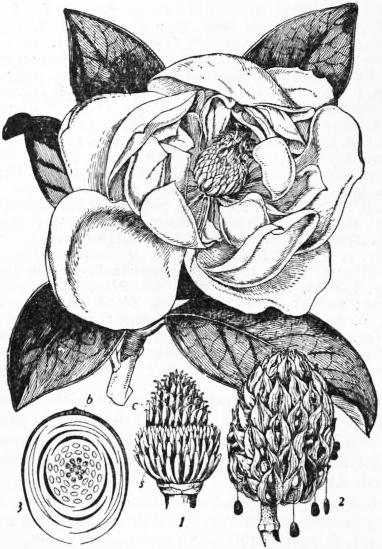
Magnolia grandiflora, shoot with flower; rather less than ½ nat. size.
1. Flower after removal of the sepals and petals, showing the indefinite stamens, s, and carpels, c. 2. Fruit—the ripe carpels are splitting, exposing the seeds, some of which are suspended by the long funicle. 3. Floral diagram, b, bract.
The first of the American species brought to Europe (in 1688 by John Banister) was M. glauca, a beautiful evergreen species about 15 ft. high with obtuse leathery leaves, blue-green above, silvery underneath, and globular flowers varying from creamy white to pale yellow with age. It is found in low situations near the sea from Massachusetts to Louisiana—more especially in New Jersey and the Carolinas. M. acuminata, the so-called “cucumber tree,” from the resemblance of the young fruits to small cucumbers, ranges from Pennsylvania to Carolina. The wood is yellow, and used for bowls; the flowers, 3 to 4 in. across, are glaucous green tinted with yellow. It was introduced into England from Virginia about 1736. M. tripetala (or M. umbrella), is known as the “umbrella tree” from the arrangement of the leaves at the ends of the branches resembling somewhat that of the ribs of an umbrella. The flowers, 5 to 8 in. across, are white and have a strong but not disagreeable scent. It was brought to England in 1752. M. Fraseri (or M. auriculata), discovered by John Bartram in 1773, is a native of the western parts of the Carolinas and Georgia, extending southward to western Florida and southern Alabama. It grows 30 to 50 ft. high, has leaves a foot or more long, heart-shaped and bluntly auricled at the base, and fragrant pale yellowish-white flowers, 3 to 4 in. across. The most beautiful species of North America is M. grandiflora, the “laurel magnolia,” a native of the south-eastern States, and introduced into England in 1734. It grows a straight trunk, 2 ft. in diameter and upwards of 70 ft. high, bearing a profusion of large, powerfully lemon-scented creamy-white flowers. It is an evergreen tree, easily recognized by its glossy green oval oblong leaves with a rusty-brown under surface. In England it is customary to train it against a wall in the colder parts, but it does well as a bush tree; and the original species is surpassed by the Exmouth varieties, which originated as seedlings at Exeter from the tree first raised in England by Sir John Colliton, and which flower much more freely than the parent plant. Other fine magnolias now to be met with in gardens are M. cordata, a North American deciduous tree 40 to 50 ft. high, with heart-shaped leaves, woolly beneath, and yellow flowers lined with purple; M. hypoleuca, a fine Japanese tree 60 ft. high or more, with leaves a foot or more long, 6 to 7 in. broad, the under surface covered with hairs; M. macrophylla, a handsome deciduous North American tree, with smooth whitish bark, and very large beautiful green leaves, 1 to 3 ft. long, 8 to 10 in. broad, oblong-obovate and heart-shaped at the base; the open sweet-scented bell-shaped flowers 8 to 10 in. across, are white with a purple blotch at the base of the petals; M. stellata or Halleana, a charming deciduous Japanese shrub remarkable for producing its pure white starry flowers as early as February and March on the leafless stems; and M. Watsoni, another fine deciduous Japanese bush or small tree with very fragrant pure white flowers 5 to 6 in. across.
The tulip tree, Liriodendron tulipifera, a native of North America, frequently cultivated in England, is also a member of the same family. It reaches a height of over 100 ft. in a native condition, and as much as 60 to 80 ft. in England. It resembles the plane tree somewhat in appearance, but is readily recognized by lobed leaves having the apical lobe truncated, and by its soft green and yellow tulip-like flowers—which however are rarely borne on trees under twenty years of age.
For a description of the principal species of magnolia under cultivation see J. Weathers, Practical Guide to Garden Plants, pp. 174 seq., and for a detailed account of the American species see C. S. Sargent, Silva of North America, vol. i.
MAGNUS, HEINRICH GUSTAV (1802-1870), German chemist and physicist, was born at Berlin on the 2nd of May 1802. His father was a wealthy merchant; and of his five brothers one, Eduard (1799-1872), became a celebrated painter. After studying at Berlin, he went to Stockholm to work under Berzelius, and later to Paris, where he studied for a while under Gay-Lussac and Thénard. In 1831 he returned to Berlin as lecturer on technology and physics at the university. As a teacher his success was rapid and extraordinary. His lucid style and the perfection of his experimental demonstrations drew to his lectures a crowd of enthusiastic scholars, on whom he impressed the importance of applied science by conducting them round the factories and workshops of the city; and he further found time to hold weekly “colloquies” on physical questions at his house with a small circle of young students. From 1827 to 1833 he was occupied mainly with chemical researches, which resulted in the discovery of the first of the platino-ammonium compounds (“Magnus’s green salt” is PtCl2, 2NH3), of sulphovinic, ethionic and isethionic acids and their salts, and, in conjunction with C. F. Ammermüller, of periodic acid. Among other subjects at which he subsequently worked were the absorption of gases in blood (1837-1845), the expansion of gases by heat (1841-1844), the vapour pressures of water and various solutions (1844-1854), thermo-electricity (1851), electrolysis (1856), induction of currents (1858-1861), conduction of heat in gases (1860), and polarization of heat (1866-1868). From 1861 onwards he devoted much attention to the question of diathermancy in gases and vapours, especially to the behaviour in this respect of dry and moist air, and to the thermal effects produced by the condensation of moisture on solid surfaces.
In 1834 Magnus was elected extraordinary, and in 1845 ordinary professor at Berlin. He was three times elected dean of the faculty, in 1847, 1858 and 1863; and in 1861, rector magnificus. His great reputation led to his being entrusted by the government with several missions; in 1865 he represented Prussia in the conference called at Frankfort to introduce a uniform metric system of weights and measures into Germany. For forty-five years his labour was incessant; his first memoir was published in 1825 when he was yet a student; his last appeared shortly after his death on the 4th of April 1870. He married in 1840 Bertha Humblot, of a French Huguenot family settled in Berlin, by whom he left a son and two daughters.
See Allgemeine deutsche Biog. The Royal Society’s Catalogue enumerates 84 papers by Magnus, most of which originally appeared in Poggendorff’s Annalen.
MAGNY, CLAUDE DRIGON, Marquis de (1797-1879), French heraldic writer, was born in Paris. After being employed for some time in the postal service, he devoted himself to the study of heraldry and genealogy, his work in this direction being rewarded by Pope Gregory XVI. with a marquisate. He founded a French college of heraldry, and wrote several works on heraldry and genealogy, of which the most important were Archives nobiliaires universelles (1843) and Livre d’or de la noblesse de France (1844-1852). His two sons, Edouard Drigon and Achille Ludovice Drigon, respectively comte and vicomte de Magny, also wrote several works on heraldry.
MAGO, the name of several Carthaginians, (1) The reputed founder of the military power of Carthage, fl. 550-500 B.C. (Justin xviii. 7, xix. i). (2) The youngest of the three sons of Hamilcar Barca. He accompanied Hannibal into Italy, and held important commands in the great victories of the first three years. After the battle of Cannae (216 B.C.) he sailed to Carthage to report the successes gained. He was about to return to Italy with strong reinforcements for Hannibal, when the government ordered him to go to the aid of his other brother, Hasdrubal, who was hard pressed in Spain. He carried on the war there with varying success in concert with the two Hasdrubals until, in 209, his brother marched into Italy to help Hannibal. Mago remained in Spain with Hasdrubal, the son of Gisco. In 207 he was defeated by M. Junius Silanus, and in 206 the combined forces of Mago and Hasdrubal were scattered by Scipio Africanus in the decisive battle of Silpia. Mago maintained himself for some time in Gades, but afterwards received orders to carry the war into Liguria. He wintered in the Balearic Isles, where the harbour Portus Magonis (Port Mahon) still bears his name. Early in 204 he landed in Liguria, where he maintained a desultory warfare till in 203 he was defeated in Cisalpine Gaul by the Roman forces. Shortly afterwards he was ordered to return to Carthage, but on the voyage home he died of wounds received in battle.
See Polybius iii.; Livy xxi.-xxiii.; xxviii., chs. 23-37; xxix., xxx.; Appian, Hispanica, 25-37; T. Friedrich, Biographie des Barkiden Mago; H. Lehmann, Der Angriff der drei Barkiden auf Italien (Leipzig, 1905); and further J. P. Mahaffy, in Hermathena, vii. 29-36 (1890).
(3) The name of Mago is also attached to a great work on agriculture which was brought to Rome and translated by order of the senate after the destruction of Carthage. The book was regarded as a standard authority, and is often referred to by later writers.
See Pliny, Nat. Hist, xviii. 5; Columella, i. 1; Cicero, De oratore, i. 58.
MAGPIE, or simply Pie (Fr. pie), the prefix being the abbreviated form of a human name (Margaret1), a bird once common throughout Great Britain, though now nearly everywhere scarce. Its pilfering habits have led to this result, yet the injuries it causes are exaggerated by common report; and in many countries of Europe it is still the tolerated or even the cherished neighbour of every farmer, as it formerly was in England if not in Scotland also. It did not exist in Ireland in 1617, when Fynes Morison wrote his Itinerary, but it had appeared there within a hundred years later, when Swift mentions its occurrences in his Journal to Stella, 9th July 1711. It is now common enough in that country, and there is a widespread but unfounded belief that it was introduced by the English out of spite. It is a species that when not molested is extending its range, as J. Wolley ascertained in Lapland, where within the last century it has been gradually pushing its way along the coast and into the interior from one fishing-station or settler’s house to the next, as the country has been peopled.
Since the persecution to which the pie has been subjected in Great Britain, its habits have altered greatly. It is no longer the merry, saucy hanger-on of the homestead, but is become the suspicious thief, shunning the gaze of man, and knowing that danger may lurk in every bush. Hence opportunities of observing it fall to the lot of few, and most persons know it only as a curtailed captive in a wicker cage, where its vivacity and natural beauty are lessened or wholly lost. At large few European birds possess greater beauty, the pure white of its scapulars and inner web of the flight-feathers contrasting vividly with the deep glossy black on the rest of its body and wings, while its long tail is lustrous with green, bronze, and purple reflections. The pie’s nest is a wonderfully ingenious structure, placed either in high trees or low bushes, and so massively built that it will stand for years. Its foundation consists of stout sticks, turf and clay, wrought into a deep, hollow cup, plastered with earth, and lined with fibres; but around this is erected a firmly interwoven, basket-like outwork of thorny sticks, forming a dome over the nest, and leaving but a single hole in the side for entrance and exit, so that the whole structure is rendered almost impregnable. Herein are laid from six to nine eggs, of a pale bluish-green freckled with brown and blotched with ash-colour. Superstition as to the appearance of the pie still survives even among many educated persons, and there are several versions of a rhyming adage as to the various turns of luck which its presenting itself, either alone or in company with others, is supposed to betoken, though all agree that the sight of a single pie presages sorrow.
The pie belongs to the same family of birds as the crow, and is the Corvus pica of Linnaeus, the Pica caudata, P. melanoleuca, or P. rustica of modern ornithologists, who have recognized it as forming a distinct genus, but the number of species thereto belonging has been a fruitful source of discussion. Examples from the south of Spain differ slightly from those inhabiting the rest of Europe, and in some points more resemble the P. mauritanica of north-western Africa; but that species has a patch of bare skin of a fine blue colour behind the eye, and much shorter wings. No fewer than five species have been discriminated from various parts of Asia, extending to Japan; but only one of them, the P. leucoptera of Turkestan and Tibet, has of late been admitted as valid. In the west of North America, and in some of its islands, a pie is found which extends to the upper valleys of the Missouri and the Yellowstone, and has long been thought entitled to specific distinction as P. hudsonia; but its claim thereto is now disallowed by some of the best ornithologists of the United States, and it can hardly be deemed even a geographical variety of the Old-World form. In California, however, there is a permanent race if not a good species, P. nuttalli, easily distinguishable by its yellow bill and the bare yellow skin round its eyes; on two occasions in the year 1867 a bird apparently similar was observed in Great Britain (Zoologist, ser. 2, pp. 706, 1016).
(A. N.)
1 “Magot” and “Madge,” with the same origin, are names, frequently given in England to the pie; while in France it is commonly known as Margot, if not termed, as it is in some districts, Jaquette.
MAGWE, a district in the Minbu division of Upper Burma. Area, 2913 sq. m.; pop. (1901), 246,708, showing an increase of 12.38% in the decade. Magwe may be divided into two portions: the low, flat country in the Taungdwingyi subdivision, and the undulating high ground extending over the rest of the district. In Taungdwingyi the soil is rich, loamy, and extremely fertile. The plain is about 45 m. from north to south. At its southern extremity it is about 30 m. wide, and lessens in width to the north till it ends in a point at Natmauk. On the east are the Pegu Yomas, which at some points reach a height of 1500 ft. A number of streams run westwards to the Irrawaddy, of which the Yin and the Pin, which form the northern boundary, are the chief. The only perennial stream is the Yanpè. Rice is the staple product, and considerable quantities are exported. Sesamum of very high quality, maize, and millet are also cultivated, as well as cotton in patches here and there over the whole district.
In this district are included the well-known Yenangyaung petroleum wells. The state wells have been leased to the Burma Oil Company. The amount of oil-bearing lands is estimated at 80 sq. m. and the portion not leased to the company has been demarcated into blocks of 1 sq. m. and offered on lease. The remaining land belongs to hereditary Burmese owners called twinsa, who dig wells and extract their oil by the rope and pulley system as they have always done. Lacquered wood trays, bowls and platters, and cart-wheels, are the only manufactures of any note in the district.
The annual rainfall averages about 27 inches. The maximum temperature rises to a little over 100° in the hot season, and falls to an average minimum of 53° and 54° in the cold season.
The town of Magwe is the headquarters of the district; pop. (1901), 6232. It is diagonally opposite Minbu, the headquarters of the division, on the right bank of the Irrawaddy.
MAGYARS, the name of the dominant race in Hungary, or Hungarians proper. Though they have become physically assimilated to the western peoples, they belong in origin and language to the Finno-Ugrian (q.v.) division of the Ural-Altaic race. They form barely half of the population of Hungary, but are by far the largest and most compact of all its racial groups. Magyar is the official language of Hungary, the official name of which (Magyarorzág, or “country of the Magyars”) enshrines the Magyar claim to predominance. While all Magyars are properly Hungarians, all Hungarians are not necessarily Magyars. “Hungarian” may be used as a generic term covering all the various races of Hungary, while “Magyar” is strictly specific to a single group. The Magyars themselves, indeed, sometimes apply the name Magyarorzág to Hungary “proper,” excluding Croatia-Slavonia, the whole kingdom being called Magyarbirodalom, the Magyar monarchy or realm. See Hungary.
MAHABALESHWAR, or Malcolmpeth, a hill station in Satara district, and the principal sanatorium in the Bombay presidency, India. Pop. (1901), 5299. It is reached by carriage from Wathar railway station (39 m.) or by motor car from Poona (119 m.). Mahabaleshwar occupies the summit of a ridge of the Western Ghats, with a general elevation of 4500 ft. above sea-level. It was established in 1828 by Sir John Malcolm, governor of Bombay, who obtained the site from the raja of Satara in exchange for another patch of territory. The superior elevation of Mahabaleshwar renders it much cooler than Matheran (2460 ft.), a sanatorium about 50 m. E. of Bombay, but its heavy rainfall (292 in. annual average) makes it almost uninhabitable during the rainy season. The mean annual temperature is 67° F. In the hottest season (March-April) an extreme of a little over 90° is reached during the day. Mahabaleshwar forms the retreat usually during spring, and occasionally in autumn, of the governor of Bombay, and the chief officers of his establishment, and has the usual public buildings of a first-class sanatorium.
MAHAFFY, JOHN PENTLAND (1839- ), Irish classical scholar, was born in Switzerland on the 12th of July 1839. He received his early education in Switzerland and Germany, and later at Trinity College, Dublin, where he held the professorship of ancient history. Mahaffy, a man of great versatility, published numerous works, some of which, especially those dealing with what may be called the Silver age of Greece, became standard authorities. The following deserve mention: History of Classical Greek Literature (4th ed., 1903 seq.); Social Life in Greece from Homer to Menander (4th ed., 1903); The Silver Age of the Greek World (1906); The Empire of the Ptolemies (1896); Greek Life and Thought from Alexander to the Roman Conquest (2nd ed., 1896); The Greek World under Roman Sway from Polybius to Plutarch (1890). His translation of Kuno Fischer’s Commentary on Kant (1866) and his own exhaustive analysis, with elucidations, of Kant’s critical philosophy are of great value. He also edited the Petrie papyri in the Cunningham Memoirs (3 vols. 1891-1905).
MAHALLAT, a province of central Persia, situated between Kashan and Irak. Pop. about 20,000; yearly revenue about £2500. Until 1890 it was one of the five “central provinces” (the other four being Irak, Ferahan, Kezzaz, and Savah), which were under a governor appointed by the shah; since then it has formed part of the Isfahan government. It is traversed by the Anarbar or Kum River, and comprises the city of Mahallat, divided into upper and lower, or Rivkan and Zanjirvan, and twenty-two flourishing villages. It was known in former times as Anar, the Anarus of Peutinger’s tables. The city, capital of the province, is situated at an elevation of 5850 ft. in 33° 51′ N., 50° 30′ E.; pop. about 9000.
MAHAN, ALFRED THAYER (1840- ), American naval officer and historian, was born on the 27th of September 1840 at West Point, New York. His father, Dennis Hart Mahan (1802-1871) was a professor in the military academy, and the author of textbooks on civil and military engineering. The son graduated at the naval academy in 1859, became lieutenant in 1861, served on the “Congress,” and on the “Pocahontas,” “Seminole,” and “James Adger” during the Civil War, and was instructor at the naval academy for a year. In 1865 he was made lieut.-commander, commander in 1872, captain in 1885. Meanwhile he saw service in the Gulf of Mexico, the South Atlantic, the Pacific, and Asia, and did shore duty at Boston, New York and Annapolis. In 1886-89 he was president of the naval war college at Newport, Rhode Island. Between 1889 and 1892 he was engaged in special service for the bureau of navigation, and in 1893 was made commander of the “Chicago,” of the European squadron. In 1896 he retired from active service, but was a member of the naval board of strategy during the war between the United States and Spain. He was a member of the peace congress at the Hague in 1899. This long and varied service gave him extensive opportunities for observation, which he supplemented by constant study of naval authorities and reflection on the interpretation of the problems of maritime history. His first book was a modest and compact story of the affairs in The Gulf and Inland Waters (1883), in a series of volumes by various writers, entitled The Navy in the Civil War; in 1890 he suddenly acquired fame by the appearance of his masterly work entitled The Influence of Sea Power upon History, 1660-1783. Having been impressed by the failure of historians to allow for the influence of sea power in struggles between nations, he was led to make prolonged investigations of this general theme (see Sea Power). The reception accorded the volume was instant and hearty; in England, in particular, it was deemed almost an epoch-making work, and was studied by naval specialists, cabinet ministers and journalists, as well as by a large part of the general public. It was followed by The Influence of Sea Power upon the French Revolution and Empire (2 vols. 1892); The Life of Nelson, the Embodiment of the Sea Power of Great Britain (1897); and Sea Power in its Relations to the War of 1812 (1905). The author’s general aim in these works—some of which have been translated into French, German and Japanese—was to make the consideration of maritime matters paramount to that of military, political or economic movements, without, however, as he himself says “divorcing them from their surroundings of cause and effect in general history, but seeking to show how they modified the latter, and were modified by them.” He selected the year 1660 as the beginning of his narrative, as being the date when the “sailing-ship era, with its distinctive features, had fairly begun.” The series as a whole has been accepted as finally authoritative, supplanting its predecessors of similar aim, and almost—in the words of Theodore Roosevelt—founding a new school of naval historical writing.
Other works by Mahan are a Life of Admiral Farragut (1892); The Interest of America in Sea Power (1897); Lessons of the War with Spain (1899); The Story of the War with South Africa and The Problem of Asia (1900); Types of Naval Officers drawn from the History of the British Navy (1901); Retrospect and Prospect, studies of international relations (1902).
MAHANADI, or Mahanuddy (“The Great River”), a river of India. It rises in 20° 10′ N., 82° E., 25 m. S. of Raipur town, in the wild mountains of Bastar in the Central Provinces. At first an insignificant stream, taking a northerly direction, it drains the eastern portion of the Chhattisgarh plain, then a little above Seorinarayan it receives the waters which its first great affluent, the Seonath, has collected from the western portion of the plain; thence flowing for some distance due E., its stream is augmented by the drainage of the hills of Uprora, Korba, and the ranges that separate Sambalpur from Chota Nagpur. At Padampur it turns towards the south, and struggling through masses of rock, flows past the town of Sambalpur to Sonpur. From Sonpur it pursues a tortuous course among ridges and rocky crags towards the range of the Eastern Ghats. This mountain line it pierces by a gorge about 40 m. in length, overlooked by forest-clad hills. Since the opening of the Bengal-Nagpur railway, the Mahanadi is little used for navigation. It pours down upon the Orissa delta at Naraj, about 7 m. west of Cuttack town; and after traversing Cuttack district from west to east, and throwing off numerous branches (the Katjori, Paika, Biropa, Chitartala, &c.) it falls into the Bay of Bengal at False Point by several channels.
The Mahanadi has an estimated drainage area of 43,800 sq. m., and its rapid flow renders its maximum discharge in time of flood second to that of no other river in India. During unusually high floods 1,500,000 cub. ft. of water pour every second through the Naraj gorge, one-half of which, uncontrolled by the elaborate embankments, and heavily laden with silt, pours over the delta, filling the swamps, inundating the rice-fields, and converting the plains into a sea. In the dry weather the discharge of the Mahanadi dwindles to 1125 cub. ft. per second. Efforts have been made to husband and utilize the vast water supply thrown upon the Orissa delta during seasons of flood. Each of the three branches into which the parent stream splits at the delta head is regulated by a weir. Of the four canals which form the Orissa irrigation system, two take off from the Biropa weir, and one, with its branch, from the Mahanadi weir. On the 31st of December 1868 the government took over the whole canal works from the East Indian Irrigation Company, at a cost of £941,368. The canals thus taken over and since completed, are the high-level canal, the Kendrapara canal, the Taldanda canal and the Machgaon canal, irrigating 275,000 acres.
MAHANOY CITY, a borough of Schuylkill county, Pennsylvania, U.S.A., 56 m. N.E. of Harrisburg. Pop. (1890), 11,286; (1900), 13,504, of whom 3877 were foreign-born, mostly Slavs; (1910 census) 15,936. It is served by branches of the Lehigh Valley and the Philadelphia & Reading railways. The borough is situated in the valley of Mahanoy Creek, and has an elevation of 1240 ft. above the sea; Broad Mountain (1795 ft.), a ridge extending through Schuylkill county, overlooks it on the S.E. The valley is a part of the anthracite coal region of Pennsylvania, fire clay abounds in the vicinity, and the borough’s principal industries are the mining and shipping of coal, and the manufacture of shirts and foundry products. Mahanoy City, originally a part of Mahanoy township (pop. in 1910, 6256), was incorporated as a borough in 1863.
MAHAR, the name of a servile caste in the Deccan, India. Their special function, apart from that of scavenger, is to act as village watchman, as guardian of the village boundaries, and as public messenger. In some parts they are also weavers of coarse cotton cloth. In 1901 their total number in all India was just under three millions.
MAHARAJPUR, a village in Gwalior state, Central India. Pop. (1901), 366. It was the scene of a battle (Dec. 29, 1843) in which Sir Hugh Gough, accompanied by the governor-general, Lord Ellenborough, defeated the insurgent army of the Gwalior state.
MAHĀVAṂSA, the Great Chronicle, a history of Ceylon from the 5th century B.C. to the middle of the 5th century A.D., written in Pali verse by Mahānāma of the Dīghasanda Hermitage, shortly after the close of the period with which it deals. In point of historical value it compares well with early European chronicles. In India proper the decipherment of early Indian inscriptions was facilitated to a very great extent by the data found only in the Mahāvaṃsa. It was composed on the basis of earlier works written in Sinhalese, which are now lost, having been supplanted by the chronicles and commentaries in which their contents were restated in Pali in the course of the 5th century. The particular one on which our Mahāvaṃsa was mainly based was also called the Mahāvaṃsa, and was written in Sinhalese prose with Pali memorial verse interspersed. The extant Pali work gives legends of the Buddha and the genealogy of his family; a sketch of the history of India down to Asoka; an account of Buddhism in India down to the same date; a description of the sending out of missionaries after Asoka’s council, and especially of the mission of Mahinda to Ceylon; a sketch of the previous history of Ceylon; a long account of the reign of Devānam-piya Tissa, the king of Ceylon who received Mahinda, and established Buddhism in the island; short accounts of the kings succeeding him down to Duṭṭha Gāmīin (Dadagamana or Dutegemunu); then a long account, amounting to an epic poem, of the adventures and reign of that prince, a popular hero, born in adversity, who roused the people, and drove the Tamil invaders out of the island. Finally we have short notices of the subsequent kings down to the author’s time. The Mahāvaṃsa was the first Pali book made known to Europe. It was edited in 1837, with English translation and an elaborate introduction, by George Turnour, then colonial secretary in Ceylon. Its vocabulary was an important part of the material utilized in Childer’s Pali Dictionary. Its relation to the sources from which it drew has been carefully discussed by various scholars and in especial detail by Geiger. It is agreed that it gives a reasonably fair and correct presentation of the tradition preserved in the lost Sinhalese Mahāvaṃsa; that, except in the earliest period, its list of kings, with the years of each reign, is complete and trustworthy; and that it gives throughout the view, as to events in Ceylon, of a resident in the Great Minster at Anurādhapura.
See The Mahāvaṃsa, ed. by Geo. Turnour (Colombo, 1837); ed. by W. Geiger (London, 1908); H. Oldenberg, in the introduction to his edition of the Dīpavamsa (London, 1879); O. Franke, in Wiener Zeitschrift für die Kunde des Morgenlandes (1907); W. Geiger, Dīpavamsa und Mahāvamsa (Leipzig, 1905, trans. by Ethel M. Coomaraswamy, Colombo, 1908).