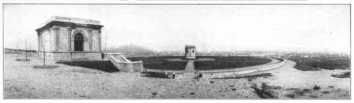
South Distributing Reservoir.
Reading edition
The distributing reservoir for the Estanzuela supply is at Guadalupe, on the foot-hills to the south of the Santa Catarina River, about 2 km. from the center of the city. The reservoir is a covered one, of reinforced concrete, and its capacity is 38,000,000 liters (10,000,000 U. S. gal.).
Plate VIII, Fig. 1.—General View of Excavation and Embankment for South Reservoir Before Lining.
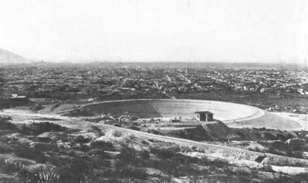
Excavation and Embankment.—The heavy slope of the ground at the selected site made the circular form the most desirable. On the low side the ground was excavated about 2 m. below the original ground line, while the excavation at the upper part of the slope was about 12 m. deep. The excavated material consisted chiefly of sillar and limestone conglomerate, which when broken up forms a calcareous clay of an excellent character for the formation of embankments, when proper care is taken. The dimensions fixed for the internal diameter of the finished concrete work of the reservoir were: 81 m. (265.68 ft.) at the top, and a depth of water of 9 m., with sides sloping 55 in 100.
Fig. 10.—South Reservoir Plan Of Excavation. Larger.
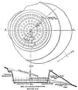
Fig. 10 is a plan of the reservoir, with a cross-section of the excavation and embankment. On the lower side the original ground line was cut down in steps, and all loose earth, roots, etc., were carefully removed. The floor of the reservoir was chiefly sillar conglomerate, a hard material that required a considerable amount of blasting for its removal. The embankments were formed in 10-cm. layers of sillar and conglomerate broken into small fragments and then rolled with 3-ton sectional rollers drawn by teams of 4 and 6 mules, which assisted in disintegrating the mass thoroughly, and produced by constant wetting a homogeneous and compact clay. The excavation and embankment were left so that 15 cm. of trimming could be done at a later date, immediately prior to the lining of the reservoir. The excavated material amounted to about 34,000 cu. m., and, of this quantity, 31,500 cu. m. were used to form the embankment; the remainder was taken to a spoil bank immediately adjoining, the black earth stripping being separated and reserved for covering the reservoir, etc. The contract prices for the excavated material placed in the embankment were:
Pesos per cubic meter
Class 1.—Material which could be removed by plows and scrapers0.60
Class 2.—This consisted chiefly of "sillar"1.09
Class 3.—Limestone conglomerate (requiring blasting)1.65
The prices (for the same classification) for material taken to the spoil bank, were 0.40, 0.80, and 1.40 pesos, respectively. Of the material taken out, 15% came under No. 1 classification, 80% under No. 2, and 5% under No. 3.
The excavation was begun at the end of May, 1907, and completed in January, 1908, by Scott and Lee, the contractors. The embankments were then allowed to stand until the beginning of July, 1908, to permit the whole to become thoroughly settled and consolidated prior to beginning the lining. In July the work of trimming the embankments and excavating for the foundations of the reservoir columns was commenced, under the Company's own administration, which completed the entire work.
Plate VI.—Details Of Beams And Columns For South Reservoir. Larger.
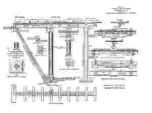
Plate VIII, Fig. 1.—Details Of Forms For South Reservoir. Larger.
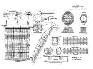
Plate VIII, Fig. 2.—View of Western Half of South Reservoir, Showing Final Setting Up of Derrick on Central Columns.
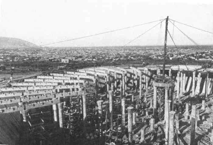
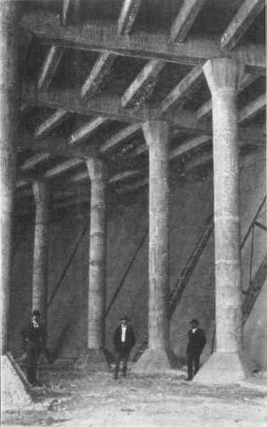
Concrete Lining and Roof.—The general arrangement and details of the side-walls, columns, and roof are shown on Plates VI, VII, VIII and IX. The principal feature consists in dividing the reservoir into radial sections and supporting the roof on 135 primary and 670 secondary beams, from 135 columns, spaced as follows:
Outerring,at34.25m.from center40columns.
2d""27.88""40"
3d""21.51""20"
4th""15.41""20"
5th""8.77""10"
6th""2.40""5"
——
Total135columns.
The inner bottom diameter of the reservoir is 70.32 m. (230.64 ft.); the upper inside diameter is 81 m. (265.68 ft.); the water depth at the overflow level is 9 m. (291⁄2 ft).
The roof was designed to carry a dead load (the earth cover) of 150 lb. per sq. ft., and a live load of 100 lb. The maximum compressive fiber stress in the concrete was assumed at 550 lb. per sq. in. for the beams, and at 350 lb. for the columns, a low figure, because of their eccentric loading. The tensile strength of the steel was taken at 14,500 and 16,000 lb. per sq. in. The twisted steel used for the column reinforcement was made at the local steel plant, but for the beams, etc., a twisted lug bar, of higher quality and greater permissible tensile stress, was used. The total quantity of steel used was 178 tons. It was calculated that the load on the column foundations would not exceed 11⁄4 tons per sq. ft. With the exception of the side-wall and floor, all the concrete was reinforced with steel, of the sizes and spacing shown on Plate VI.
General Construction and Erection Scheme.—The question of ordinary forms, requiring very heavy timber work, was a serious one, as suitable lumber is very expensive in Mexico; and the necessity of finishing this reservoir before the end of the first term allowed under the concession, which expired on December 31st, 1908, led to the adoption of what the writer believes is an original scheme for so large a structure. This scheme was to cast the columns in short sections, mould the radial and secondary beams as separate members, and then place them in position with derricks. At the same time, in the case of the beams, it was important not to sacrifice either the benefit of that part of the slab which is ordinarily assumed to act as a part of the beam, or the additional strength due to continuity; and, in case of the columns, the strength due to the reinforcement extending from the foundation to the beams.
The T-beam section was secured by notching the tops of the moulded members, with notches 10 cm. deep, throughout the lengths of the beams, as shown on Plate VI. A computation of the maximum flange increment shows that these notches are sufficient to transfer the flange stresses to the stem, but, for additional security, flat steel bars were bent to a Z-shape and embedded in the top of the beam, about 60 cm. apart. Continuity in the beams was secured by carrying the steel to the tops of the beams over all supports, and, after erection, concreting them into the roof slab. The secondary beams, after casting, were dropped into recesses left in the radial beams for the purpose.
Concreting, Mixing, etc.—The radial beams and column sections were cast as nearly as possible under their ultimate positions; the secondary beams were cast outside and immediately adjoining the reservoir.
The rock and sand was brought from the Company's crushing plant, in 3-cu. yd., side-dump cars, running on a 30-in. track by gravity a distance of 1 km., the last 150 m. requiring hauling with 6 mules. The cars returned all the way to the crusher by gravity. These cars dumped the material into bins on the high ground above the reservoir; from there it was hoppered into cars which carried to the mixer all the material for one batch of concrete. Two No. 1 Smith mixers were used, and from 25 to 30 batches per hour could be handled in each machine.
The concrete was transported from the mixers to place in 1⁄2-cu. yd., 18-in. gauge, swivel, steel dump-cars pushed by two men. All the concrete used in the bottom of the reservoir, for the main beams, columns, and floor, amounting to about 2,460 cu. m., was dumped through a chute into smaller cars. The chute had so many baffle-plates and bolts that it resembled a gravity mixer, but, although it was 12 m. long, it effectively prevented the separation of the materials.
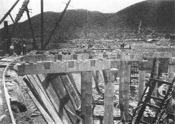
Concrete Placing and Moulding.—The square foundations for the columns were deposited in situ, a recess being left for the reception of the pedestals, which were moulded in place afterward. The capitals and pedestals were cast in one piece, and the columns in 1.21-m. (48-in.) sections, eight 5-cm. holes being left in them by using wrought-iron pipes, held in place by templates and removed when the castings were about 3 hours old. The columns were erected by threading them on the 15.8-mm. (5⁄8-in.) reinforcing rods, which extended from the pedestals up through the capitals. The rods were in two lengths, arranged to lap alternately at one-fourth, the center, and three-fourths of the height of the columns. In erection, a light timber frame was used in conjunction with the derrick, and, as the columns were placed, the reinforcing steel was grouted solid with 1:2 cement mortar.
All the erection was done with a combined stiff-leg or guy derrick, having an 80-ft. boom and a 50-ft. mast, and fitted with a 30-h.p. Lambert hoisting engine. The derrick was erected seven times at the circumference, and its final position was on top of the center columns. The moving of the derrick a distance of about 45 m. and its subsequent erection occupied usually about 48 hours. The erection work was carried on continuously, day and night, the placing of the whole of the radial and secondary beams and columns occupying 21⁄2 months.
Forms.—As the erection scheme was designed to reduce the cost of forms, economical construction was of considerable importance. The wall was formed in 40 panels, about 6 m. wide and 11.27 m. high. The chief object in arranging them in this manner was to permit an expansion joint, 30 cm. wide, at each panel; this joint was not filled until after the completion of the roof, when the temperature inside the reservoir was uniform and not subjected to such great fluctuations as if exposed alternately to the hot sun and comparatively cool nights. The range of temperature during the construction period sometimes amounted to 80° Fahr. in 24 hours.
The expansion joints were left to the last, when a uniform temperature of about 70° inside permitted the filling of the joints, thus avoiding all trouble from expansion cracks.
The forms are shown in detail on Plate VII. They consisted of shutters stiffened with four trapezoidal trusses. The bottom posts of the trusses were fixed in holes formed in the foundation block; they were propped back from the embankment at the top, and secured to anchorages by iron rods.
Six sets of these forms were used to construct the whole wall. The concrete was placed in position through stove-pipe chutes, 20 cm. in diameter, in continuous layers, the workmen treading and spading it well as it was deposited. The forms were allowed to remain 4 or 5 days, and were then struck and removed to another section. The pedestals and capital forms were of lumber, and five of each were used to cast the total number required. In the column sections the outer steel forms used in the manufacture of the Estanzuela pipes were adapted for this purpose. The radial beam forms, shown on Plate VII, were arranged with internal wedge-shaped blocks to mould accurately the recess for the secondary beams. The bottom forms were left attached to the beams for 28 days, but the sides and ends were removed after 24 hours. Eight forms were sufficient for the whole 135 beams.
For the secondary beams, 29 forms were used for the 670 beams, the bottom lumber also being left until they were mature for handling.
By referring to the cross-section of the secondary beam, it will be noticed that it is jug-shaped, shelves being left on either side for the support of the roof forms, which were placed after the secondary beams had been properly grouted to the radial ones. The lagging was laid diagonally, so that the short diameter was slightly greater than the distance between the beams. This greatly facilitated the removal of the lagging, as it was merely necessary to strike the wedge-shaped fillets beneath, and turn them clockwise, after tearing out the end lagging.
Plate IX, Fig. 1.—View of Separately Moulded Secondary Beams in Yard Below South Reservoir.
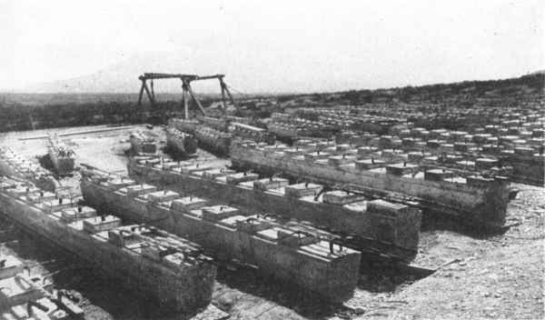
Plate IX, Fig. 2.—Setting Primary Beams, South Reservoir.
The writer believes that the adoption of forms of this type, rather than the ordinary kind, led to a saving of lumber of about 400,000 ft. b. m. During the erection and placing of the concrete, all the joining surfaces were carefully picked and cleaned, particular care being taken at the junction of the secondary with the radial beams, and the upper surfaces of all beams before laying the roof slab.
After the greater part of the roof was completed, the floor was laid in those sections where it was protected from the sun's rays. The concrete was placed in two 15-cm. thicknesses, and the work was carried on night and day, without any joints. The laying of the floor occupied 8 days, or an average of nearly 100 cu. m. daily.
Plate X, Fig. 1.—View of Completed Section of South Reservoir. Expansion Joints in Side-Wall Not Yet Filled.
Proportions of Concrete.—All the concrete work was brought to a smooth face by careful spading, no plastering being used throughout the reservoir, except in the superstructures. The work was kept well watered in every case for about 15 days. The whole of the concrete work in connection with the reservoir was completed in 51⁄2 months. The concrete for the columns and foundations was a 1:3:5 mixture, the aggregate consisting of equal parts of 19-mm. (3⁄4-in.) and 38-mm. (11⁄2-in.) crushed stone. The remainder of the concrete, except that for the roof, was a 1:2:4 mixture, the aggregate also consisting of equal parts of 19-and 38-mm. stone. With the exception of a short length of the side-walls, the sand used was that manufactured by the Company. When the crushing plant was unable to produce all the sand required, the Hornos sand (see Table 3) was used in the side-walls in equal proportions with the crusher sand.
Reservoir Outlet and Entrance Tower.—The outlet, 61 cm. (24 in.) in diameter, leads from a well in the center of the reservoir and passes under the floor and embankment to an outside valve-pit, 89 m. from the center. This pipe was laid in a trench in a solid cutting before the construction of the embankment, and was encased in 1:4:8 concrete. Where it passes under the embankment a 1:2:4 concrete cut-off wall, 3.6 m. wide, 2.5 m. high, and 1 m. thick, was placed across it at right angles. The cast-iron pipe is curved upward in the central well, and has a bellmouth on which rests a movable circular copper screen.
Above the outlet well, and on the roof of the reservoir, there is a central tower, giving access to the interior by a steel stairway. This tower also serves as a main ventilating shaft, and in it are arranged the guide-screens and gearing for raising them for cleaning purposes. In addition to the ventilation provided in the tower, 20 circular openings, 30 cm. in diameter, are carried through the roof of the reservoir at the circumference and into the parapet walls.
Inlet Gate-House, etc.—The inlet gate-house is above the reservoir and about 541⁄2 m. from its center. The conduit enters at 589.00 m. above datum, and the gate-house contains the valves for controlling the inlet pipe to the reservoir, the by-pass, overflow, scour-out pipe, and the copper screens. The inlet, which is 45.7 cm. (18 in.) in diameter, is of cast-iron flanged pipes, carried on iron hangers on the side-wall of the reservoir, and, at a point 90 cm. above the floor level, it is turned at right angles to the side-wall and carried on concrete piers to the center of the first row of columns. The end of the pipe is closed by a blank flange, and the water is deflected at right angles through two 30-cm. (12-in.) branches, for the purpose of setting up a slight circular motion as it enters the reservoir.
The valve-pit is clear of the embankment, and in it are brought together the main supply and by-pass pipes on which are placed two 61-cm. (24-in.) sluice-valves; and between them there is a 20-cm. (8-in.) scour-out pipe, for emptying the reservoir into an adjoining arroyo. The arrangement of the valves gives complete control over the contents of the reservoir.
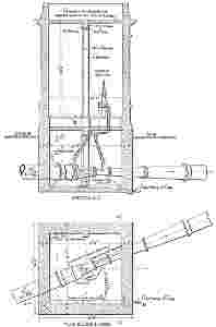
Venturi Meter-House.—Fig. 11 shows the arrangement of the Venturi meter and its automatic register in a house over the main supply pipe. This house is designed to form a feature of the entrance gateway of the reservoir grounds, which cover an area of 12 hectares.
Fig. 11.—Venturi Meter-House. Larger.
General.—The roof of the reservoir has been laid out as a garden, and the embankments are turfed. The intention is to develop the Company's land as a public park, as it commands fine views of the city and the surrounding mountains. An inspector's house has been built, and a private telephone line provides for communication with the Estanzuela intake and also with the general offices in the city.
Plate XVIII, Fig. 1.—View of South Reservoir, Looking Toward the City.