Main Outfall Sewer.
Reading edition
The direction of the main outfall sewer was determined after a thorough study of all the available land lying to the north and northeast of the city, as it was the intention of the Company to utilize for irrigation purposes the sewage and any surplus waters that might be developed. The best available site was found to be about 12 km. north of the city, a little northwest of the village of San Nicolas de los Garzas, as shown on Plate II. The long length of outfall required was justified by the cheap cost of the land and its excellent character for sewage irrigation. The sewer was designed for a capacity of 90,000,000 liters a day (36.76 cu. ft. per sec.) in order to allow for conveying surplus waters as well as sewage.
Plate XXII.—Outfall Sewer: Plan Of Ground Showing Sewer; Also Details Of Various Sections. Larger.
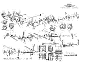
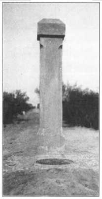
The outfall intercepts the two main branches of the city sewers at Calle de Allende and Calle de Tapia, and its total length is approximately 11,900 m. The chief type adopted is shown on Plate XXII. It is formed with an invert of radial bricks laid in 1:2 cement mortar, on a foundation of 1:3:5 concrete approximately 7 cm. thick. As the ground was chiefly in hard sillar, only a little concrete was required to mould the bottom to the correct shape. The arch was formed of special radial bricks, 15 cm. (6 in.) deep, laid in cement mortar. These bricks were adopted in preference to concrete, owing to the heavy cost of sand and rock, due to the long haul, and for the purpose of obtaining rapid work. Plate XXI shows the sewer arch, and one of the ventilating columns and manholes. The bricks were obtained from the local brick plant, and form a very satisfactory material for sewers, being well burnt, thoroughly hard, and absorbing not more than 71⁄2% of their weight of water. The contract prices for the labor on the brickwork were 1.25 pesos per sq. m., and 1.38 pesos for the arch.
Plate XXI, Fig. 1.—View of Arch, Outfall Sewer.
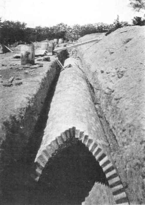
Plate XXI, Fig. 2.—Ventilating Column and Manhole, Outfall Sewer.
The general route of the sewer is very direct, long straight lines of several kilometers being possible, and these were joined by curves of approximately 30 m. radius. The gradient of the sewer invert is 0.2% (1 in 500) which is approximately the general fall of the ground northward from Monterrey.
The total quantity of excavation was as follows:
No. 1, soft earth8,960cu. m.
No. 2, sillar18,492"
No. 3, conglomerate rock9,822"
———
Total37,274cu. m.
The contract prices for this excavation were: for No. 1, 32 cents; No. 2, 85 cents; and No. 3, 2.17 pesos per cu. m.
All the excavation was in perfectly dry ground. Where the sewer was partly out of the ground it had a foundation of concrete, 1.75 m. wide, from 15 to 23 cm. thick, below the bottom of the brickwork, and carried up to the springing of the arch, and a well-tamped embankment, with slopes of 11⁄2 to 1, to protect the sewer to a height of 30 cm. (12 in.) above the arch. For 342 m. at the Monterrey end of the line, the sewer was constructed in tunnel, from, the open end and from two intermediate shafts. The tunnel throughout was in sillar, and the contract price for excavation was 24.50 pesos per lin. m. This work was done without timbering of any kind, except at the shaft lengths. Plate XXII shows the lining of the tunnel, which was of concrete with a brick invert. At four places the sewer passes under main railway tracks, which at these points were carried on steel girders supported on concrete abutments, the sewer being carried under the tracks in the ordinary way.
Bridges.—At three points the sewer was carried over arroyos on reinforced concrete girders. No. 1, at Station 5,600, consisted of four 10-m. spans; No. 2, at Station 8,365, over the Estanscia Arroyo, consisted of nine 10-m. spans; and No. 3, at Station 8,960, over the Topo Chico Arroyo, consisted of three 10-m. spans. One of these bridges is shown on Plate XXIII. They were designed as two parallel continuous girders with connecting top and bottom slabs. The concrete for the girders was a 1:21⁄2:31⁄2 mixture, the sand being from the crusher and the rock gauged to pass a 19-mm. (3⁄4-in.) screen. The inside was rendered with a coat of 1:1 cement mortar, 7 mm. thick, for water-tightness.
Plate XXIII, Fig. 1.—Forms for Main Girders, Estanscia Bridge, Outfall Sewer.
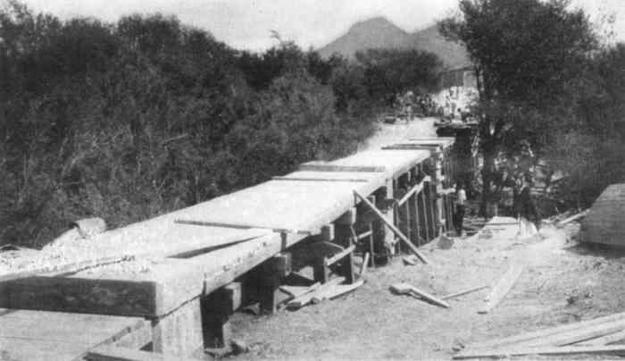
Plate XXIII, Fig. 2.—View of Estanscia Bridge, Completed.
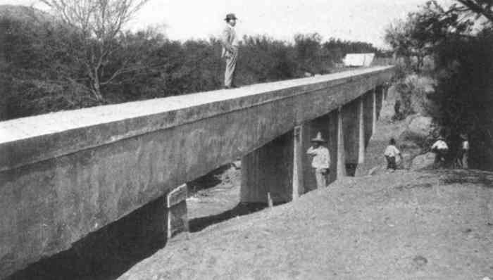
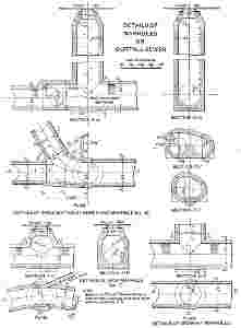
The piers of the Estanscia Bridge (Plate XXIII) were carried down through soft earth to a stiff clay from 41⁄2 to 6 m. below the surface, and the foundations were spread so that the pressure would not exceed 1 ton per sq. ft. The ends of the bridges were protected by rubble wing-walls supporting the embankment over the sewer. A 1:3:5 concrete was used for the upper part of the piers, and the lower part was of the same mixture with 30% of large boulders. There are 70 manholes (Fig. 19) along the line of the sewer, and they vary from 150 to 230 m. apart. The sewer is ventilated with 30 concrete towers (Fig. 18, and Fig. 2, Plate XXI), 2.9 m. high, having 20-cm. (8-in.) shafts.
Fig. 18.—Details Of Ventilators On Outfall Sewer. Larger.
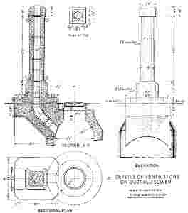
Fig. 19.—Details Of Manholes On Outfall Sewer. Larger.
The works for the outfall sewer were carried out satisfactorily under a contract with Mr. John Phillips, of Mexico City, the Company supplying the greater part of the materials. The work was begun on March 16th, and finished on November 12th, 1908.