Sewage Disposal Works and Irrigation Lands.
Reading edition
For the purpose of disposing of the sewage and using it profitably, the Company purchased 909 hectares (2,246 acres) of land from the Community of San Nicolas de los Garzas, the outfall sewer being carried to the southwestern boundary of the land acquired. This area has a general fall in all directions to the northeastern boundary, with a gradual fall of about 25 m. across the diagonal of the land. The area purchased was practically virgin land, only small portions having been cultivated. The greater part was covered with a growth of mezquite trees and small shrubs. The quality of the land is excellent, if properly irrigated, and capable of yielding abundant crops of every description. The limits of this land are shown on Plate II.
Sewage Purification Tanks.—For the purpose of obtaining a satisfactory effluent to discharge on the land without causing nuisance, the Company built a system of detritus chambers and liquefying tanks at the end of the outfall sewer. One difficulty to be faced, in designing these works, was the fact that there were no data regarding the probable quantity of dry-weather sewage, nor any particulars as to its general character; there was also the probability that the outfall sewer would have to carry large quantities of surplus water. Therefore, the system was designed so as to be capable of extension if necessary, and the sizes of the various tanks were limited at present, because of the septic processes which would be set up in the long length of outfall sewer. The tanks were designed to deal with 10,000,000 liters of sewage proper per day, and the channels, etc., were proportioned to take the full flow of the sewer if necessary. Provision was also made for discharging large volumes of surplus water directly on the land, independent of the tanks. To do this a by-pass was taken from the sewer a short distance before reaching the site of the tanks. By properly timing the flow, arrangements could be made to discharge these waters in the early hours of the morning, by allowing the scour-pipes in the distribution system to be opened at night when the domestic sewage flow was at its minimum. As the area of land available is very great, the degree of purification in the tanks was relatively unimportant; the object to be obtained consisted chiefly in distributing on the land an effluent which would be innocuous and clear.
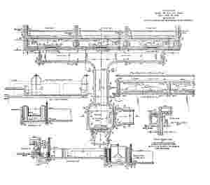
The general design of the works is shown on Plate XXIV, and they consist essentially of a screen chamber, duplicate detritus tanks, and three liquefying tanks. There is also a sludge-pit 629 m. from the tanks.
Plate XXIV.—Sewage Disposal Works At San Nicolas De Los Garzas General Plan Of Detritus And Liquefying Tanks; With Details Of The Latter. Larger.
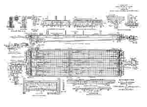
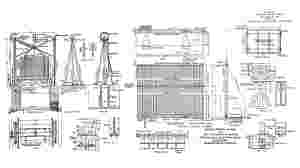
Screen Chamber and Detritus Tanks.—Enlarged details of the screen chamber are shown on Plate XXV. The invert, where the sewer enters the screen chamber, is 489.45 m. above datum. This chamber has duplicate screens which are fully detailed on Plate XXX. For cleaning purposes the screens are raised by a steel-framed head-gear, which is arranged so that they may be lowered to a small traveling bogie, out of the way of the screen chamber.
Plate XXV.—Sewage Disposal Works At San Nicolas De Los Garzas. Details Of Detritus Chambers And Inlet Channels. Larger.
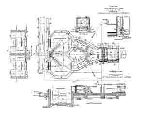
Plate XXVI.—Sewage Disposal Works At San Nicolas De Los Garzas Detritus And Liquefying Tanks; Details Of Distributing Channels. Larger.
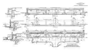
Plate XXX.—Sewage Disposal Works At San Nicolas De Los Garzas. Details Of Screening Apparatus. Larger.
From the screen chamber there are two main channels, 1.22 m. wide, branching to the two concrete detritus chambers. Each channel has a square penstock, so that the sewage can be diverted into either chamber when necessary.
The detritus chambers are octagonal in plan, 4 m. in diameter, and each is provided with an outlet weir 1.50 m. wide. At the weir level the chambers have a depth of 1.75 m., with drainage channels below that level. The coping is 1 m. above the outlet weir of the detritus tanks. To drain off these chambers, each has a scour-out pipe, 30 cm. in diameter, controlled from valves with spindles carried above the coping level. Each of these pipes is connected to a central chamber, and leads to a 56-cm. (22-in.) sludge-pipe. The chambers as designed are of smaller capacity than those usually provided, but, as all surface water is strictly excluded from the sewerage system, the quantity of detritus reaching the chambers may be small. The velocity through them when both are in use will be approximately 0.082 m. (0.27 ft.) per sec.
From these chambers the sewage is carried to the three liquefying tanks by a main channel, 11.5 m. long and 1.50 m. wide.
Plate XXVII, Fig. 1.—Cast Concrete Beams Being Placed in Position, Liquefying Tanks.
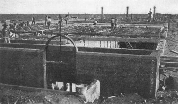
Plate XXVII, Fig. 2.—Inlet Weirs to Liquefying Tanks, During Construction.
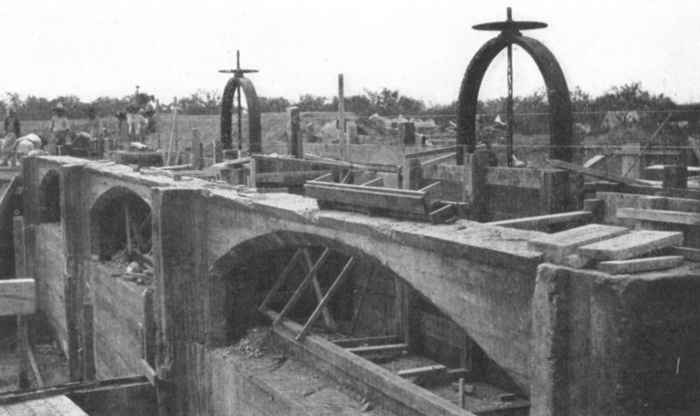
Plate XXVIII, Fig. 1.—View of Liquefying Tanks, from Inlet End.
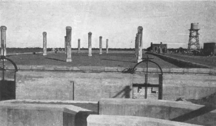
The tanks are of concrete and have reinforced concrete roofs. Each is 66 m. long and 6 m. wide; the minimum depth for the sewage is 1.50 m. at the outlet end, and 2.25 m. at the inlet, increasing to a maximum depth of 2.75 m. at the lowest depth at the scour-out channel. Their combined capacity is 2,500,000 liters, which is equivalent to 6 hours' flow of the quantity of sewage for which they were designed. The sewage passes from the main channel, through penstock-valves which control the flow, into one or the other of the tanks. From these valve openings it flows over concrete weirs, 5 m. long, and is deflected to the bottom of the tank by a reinforced concrete scum-plate, extending across each tank, with a clearance of 15 cm. at each end. This scum-plate is 1.5 m. deep and 10 cm. thick, and is placed 40 cm. from the end walls.
Plate XXIX.—Sewage Disposal Works At San Nicolas De Los Garzas; Details Of Outlet Channels And Weir Box. Larger.
The details of the concrete division and outside walls are shown on Plate XXIX. The floor was constructed in two layers, and its surface is divided into 6 channels formed by small walls, 20 cm. wide and 15 cm. deep, the object of these channels being to facilitate the cleaning of the floor by scouring it out to a specially arranged channel at the deepest point of the tank, near the inlet end. Each scour-out channel has a 30-cm. (12-in.) gate-valve, controlled from the roof of the tank, the three scour-pipes meeting in a concrete chamber outside of the tanks, from which a 56-cm. (22-in.) concrete pipe discharges the contents of the tanks to the sludge-pit during cleaning operations. The velocity through the tanks, when they are used in combination, is 0.0253 m. (0.083 ft.) per sec., the tanks being made as long as economically possible, in order to obtain this low velocity and thus permit the proper sedimentation of the suspended matters. The roof of each tank is 1 m. above the weir level. Each tank has four ventilating columns, 3.7 m. high and 30 cm. in diameter, vitrified clay pipes, with an exterior casing of contrete, being used for the shafts. The roof is enclosed within parapet walls, and is covered with a layer of earth 25 cm. thick.
The outlet channel from the tanks leads to a measuring chamber, 3 m. square, as shown on Plate XXIX. This chamber is fitted with penstocks, 1.83 m. wide, and measuring weirs. From this chamber the sewage is delivered to two main irrigation ditches, which distribute the sewage in two directions, one northward and the other to the western extremity of the lands.
Construction of Tanks.—The excavation for the tanks was in soft earth for a depth of 11⁄2 m.; the lower depths were in a firm foundation of sillar and calcareous clay. The total excavation in the tanks, channels, etc., was 8,335 cu. m., and the actual cost was 453⁄4 cents per cu. m. To facilitate the construction, about six-tenths of the concrete beams were cast as single monoliths and placed in position by sliding them across the tanks on temporary timbers. The remainder of the beams, the roof, and the slab were placed in position in the ordinary way with timber forms. The total quantity of concrete placed was 1,360 cu. m. A 1:21⁄2:41⁄2 concrete was used for the walls, channels, etc., and a 1:2:3 mixture for the roof slab and beams.
Table 14 gives the average cost per cubic meter for all the concrete work.
TABLE 14.—Average Cost per Cubic Meter for Concrete in Tanks.
Pesos per cubic meter. Pesos per cubic meter.
Labor:
Mixing and placing 5.20
Carpenter work in forms, framing, etc. 4.20
———
Total labor cost 9.40
Materials:
Screened gravel 4.04
Sand (from neighboring arroyo) 4.98
Cement (including hauling) 15.19
Lumber, nails, and other supplies 1.90
———
Total materials cost26.11
Total cost of concrete per cubic meter 35.51
Sludge-pit.—The sludge-pit, used when cleaning out the tanks, is carried 639 m. northward, far enough to get the available fall to drain the bottom of the detritus chambers and liquefying tanks. The drainage pipe was formed of 56-cm. (22-in.) concrete tubes. The sludge-pit is merely an excavation in the earth 20 m. square and 2 m. deep, the sides having a slope of 11⁄2 to 1. An overflow drains the pit to an irrigation ditch, the solid matter being allowed to settle and the liquid to drain off. From time to time it is proposed to dig out the solids and plow them into the land.
General.—To the east of the tanks a 3-roomed house has been built for the inspector.
In order to provide a good supply of water for cleaning operations, a well 22 m. deep has been sunk and is fitted with pumps operated by an Eclipse windmill, 4 m. in diameter, on a tower 22 m. high, which delivers the pump water to a circular wooden tank of 20,000 liters capacity.
The work in connection with the purification tanks was carried out by the Company's own staff; it was begun on September 10th, 1908, and practically completed by the first week in January, 1909.
At the time of writing, the tanks have to deal with the sewage from a population of only 10,000 persons, as only from 15 to 20% of the connections have been made. The sewage, therefore, has been diluted with several times its volume of surplus water, and the necessary scum on the top of the sewage in the tanks has not yet assumed the usual thick matty condition observed in most systems. As there are no available means in Monterrey of having proper determinations made of the degree of purification which takes place in the passage of the sewage through the liquefying tanks, a few simple tests have been made. These tests were limited to the determination of the amount of oxygen absorbed in 4 hours, and show a purification of 50% in passing from the detritus chambers to the outlet. The sewage, although very black and full of suspended matter as it enters the tanks, leaves them in a very clarified condition.
Of the total area of land acquired by the Company, 904 hectares (2,234 acres) have been leased to the Monterrey Railway, Light, and Power Company, for 99 years, the Water-Works Company reserving 5 hectares (12 acres) absolutely for future extensions of the sewage works. By giving 12 months' notice, the Company also reserves the right to utilize any part of 145 hectares (358 acres) near the tanks, should it be required at any time in the future for sewage purification purposes.