Distributing Reservoir at Obispado.
Reading edition
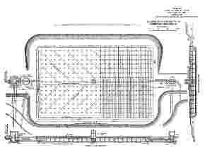
The main distributing reservoir for the San Geronimo gravity supply is immediately below the historic Obispado (Bishop's Palace), at the western limits of the city. The general arrangement and lay-out is shown on Plate XIII.
Plate XIII.—General Plan and Sections, Obispado Reservoir. Larger.
Valve-House.—The invert of the conduit from San Geronimo, where it enters the valve-house, is 558.50 m. above datum. The valve-house, which is built in the center of the reservoir, is shown on Fig. 2, Plate XVIII. One of its special features is the provision of the main overflow at this point instead of within the reservoir proper. The inlet, main supply tunnel, independent by-pass overflow, scour-out pipes, gate-valves, and screens, are all controlled within the valve-house.
Plate XVIII, Fig. 2.—View of Roof of Obispado Reservoir, Looking North.
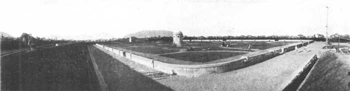
Reservoir.—The reservoir is rectangular, 126 by 81 m. (413.28 by 265.68 ft.) at the top, and has a water depth of 4 m. (13.1 ft.). In the design it was necessary to limit it to the lowest economical depth, so as to increase the static pressure over the low-pressure district as much as possible.
Excavation and Embankment.—The excavation, except for a depth of about 1 m. which was in black soil, was chiefly in a disintegrated "sillar" stratum of a heavy clayey nature, the greater part of which could be handled conveniently with plows and scrapers; the actual foundation on the eastern half required blasting for the final depths.
The total excavation amounted to 56,479 cu. m., of which 7,255 cu. m. were placed in the embankment, the remainder being deposited in the immediate neighborhood of the reservoir. The final trimming of the banks, which were left 30 cm. full, was not undertaken until the lining was begun. The work was done under contract with Mr. J. S. Nickerson, of Monterrey. The excavation had only one classification, and the contract prices were 0.50 peso per cu. m. for material carried to spoil banks, and 1.00 peso for material placed in the embankment. The excavation was begun in December, 1907, and completed in April, 1908. The work was then left standing until the end of 1908 to allow the banks to consolidate thoroughly prior to lining, which was begun on January 4th, 1909.
Concrete Lining and Roof.—Plate XIII shows the general plan and sections, the main feature being the simple division of the reservoir into 24 rows of columns longitudinally and 15 rows transversely, making a total of 360 columns, less the four left out at the central tower. All the columns are 5 m. apart both ways. The roof was designed for a live load of 100 lb. and a dead load of 150 lb., the same as at the South Reservoir. With the exception of the floor, all the concrete work was reinforced with twisted steel lug bars. The foundation load on the columns for the eastern half of the reservoir is 0.9 ton per sq. ft.; that on the columns for the western half, where the foundation is of very hard sillar and conglomerate, is 1.95 tons per sq. ft.
Under-drainage of the Floor.—To provide for proper drainage in case of seepage, the floor was underdrained with rubble drains, 30 cm. wide and 23 cm. deep, filled with large round gravel carted from the bed of the Santa Catarina River. The total length of these underdrains is 1,160 m. In order to facilitate the detection of any seepage, they were conducted to a permanent inspection pit outside of the reservoir.
Main Distributing Conduit.—The main distributing conduit is laid along the inside of the reservoir, at the inlet end, and carried on elliptical arches of 2 m. span to a height of 71 cm. above the finished floor level. This conduit is 76 cm. high and 45.7 cm. wide, and it branches in two directions from the inlet tunnel to each side of the reservoir, its total length being 69 m. In order to prevent any stagnation and to give a continuous circulation, the water is delivered at eight points, in the length of the distributing pipe, through square openings with semicircular tops, the areas of the openings increasing toward the ends. These inlets are placed so that the current will not strike the roof columns.
Outlet Tunnel and Valve-House.—The outlet tunnel is at the north end of the reservoir, and was excavated in hard sillar rock. The tunnel is lined with concrete 30 cm. thick, the finished internal dimensions being 1.52 by 0.91 m. The length of the tunnel is 22.5 m. to the point where it enters the outlet-house. This house is divided by a wall 45 cm. thick, which supports a 76-cm. (30-in.) penstock-valve. The supply pipe to the city leaves this chamber in the west wall, and is also fitted with a 76-cm. penstock-valve. The supply pipe has a copper screen of the same design and dimensions as those in the inlet-house. A 30-cm. (12-in.) scour-out pipe in this chamber provides for draining the contents of the reservoir to a neighboring irrigation ditch, when necessary.
The superstructure of the valve-house is of concrete, and at the floor level there are bevel-geared head-stocks to raise the valves, etc.
By-Pass and Supply Pipes.—The by-pass and supply pipes are carried below the reservoir embankment to join the main 76-cm. (30-in.) cast-iron distributing pipe to the city. For this short distance they were constructed of concrete, 76 cm. in internal diameter, 10 cm. (4 in.) thick, reinforced with 61⁄2-mm. square steel longitudinal rods, 30 cm. from center to center in the circumference, and hooped with 61⁄2-mm. square steel rods spaced 30 cm. apart. The concrete forming these pipes was a 1:11⁄2:21⁄2 mixture.
Parapet Walls.—The parapet walls have 12 piers at each side and 8 at each end. In these piers there are ventilating openings branching at the top to each side of the parapet, with outlets provided with cast-iron screens. This arrangement gives 4 sq. m. of ventilating space (exclusive of that provided in the central tower), equally distributed at 40 points around the walls of the reservoir.
General Construction Scheme.—The concrete mixing plant, which consisted of two No. 1 Smith mixers, was arranged in connection with the bins and hoppers for the rock and sand on the high ground to the west, and from there the material was conveyed on a framed timber gangway carried right across the center of the reservoir, as shown by Fig. 1, Plate XVII. From this central platform the concrete for the columns was filled from stages placed on the top of traveling towers, 5 m. high, which were run between two rows of columns on standard-gauge rails laid on the floor of the reservoir. By this arrangement 24 columns could be filled from each length of track. A main narrow track was also laid right around the reservoir, with the necessary turn-outs.
Plate XVII, Fig. 1.—Filling Primary Beams from Traveling Tower, Obispado Reservoir.
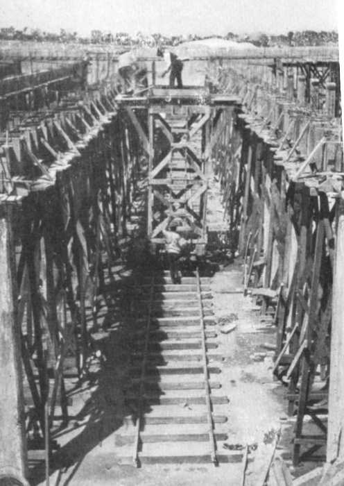
Plate XV, Fig. 1.—Construction of West Side-Wall of Obispado Reservoir.
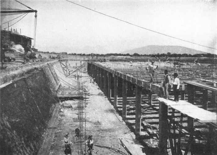
Plate XV, Fig. 2.—Primary Beams and Columns, Obispado Reservoir.
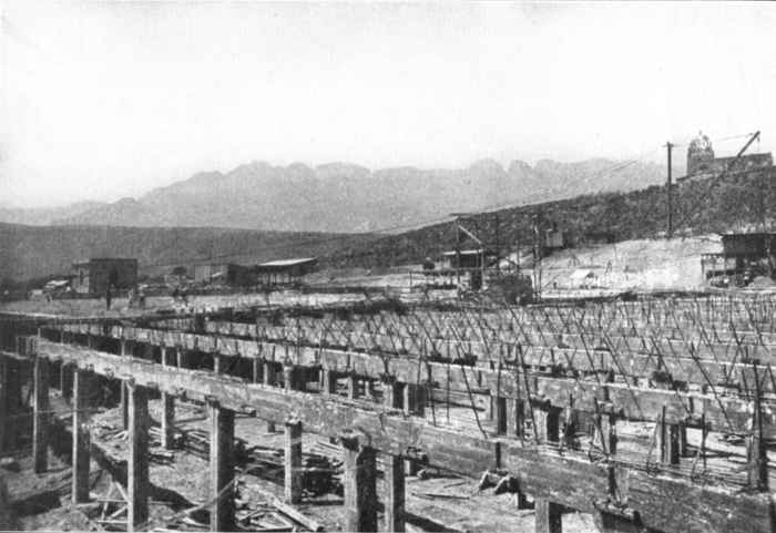
Plate XIV.—Details Of Forms For Concrete Work, Obispado Reservoir. Larger.
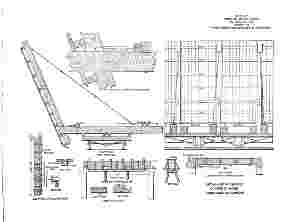
The forms for the columns, primary and secondary beams, are shown on Plate XIV. The side forms for the primary beams were struck in 24 hours, so as to economize lumber; but the bottom lumber was left in position for 28 days. To avoid much unnecessary timber, the secondary beam forms were supported at the ends on reinforced concrete corbels cast on the primary beams.
For placing the side-walls, a special traveling form was used, the details of which are shown clearly on Plate XIV. At the end of each form an expansion joint of 25 cm. was left to be filled after the roof was placed in position. The concrete was delivered to the wall through stove-pipe chutes, and carefully spaded by workmen in the limited space between the forms and the embankment. The wall form was removed after 36 hours, by loosening the jacks and pulling forward the hooked tie-rods. This form is also shown on Fig. 2, Plate XVI.
Plate XVI, Fig. 2.—Traveling Side-Wall Form, Obispado Reservoir.
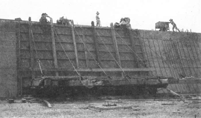
Plate XVI, Fig. 1.—Preparing Floor for Concreting, Obispado Reservoir.
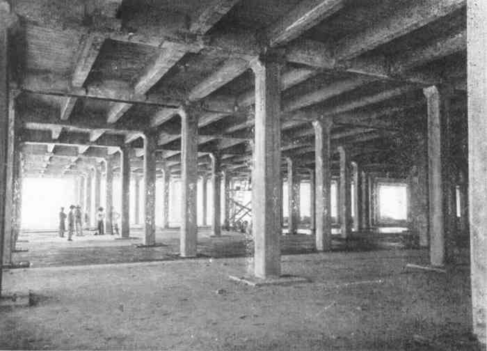
The concreting of the roof slab was carried on continuously, and, when partly completed, the floor was laid in the shade. The bottom layer of the floor, 13 cm. thick, was laid in continuous panels between the columns, and brought to a fairly smooth surface. On this surface, after keeping it wet for 10 days and then allowing it to dry thoroughly, a layer of asphaltum, supplied by the American Asphaltum and Rubber Company, of Chicago, was placed. The work was done by ordinary Mexican laborers after they had received a few days' instruction from one of the Asphaltum Company's superintendents. The surface of the lower layer was kept perfectly clean, and then received one coat of "Pioneer" paint. The asphaltum, heated in a boiler inside the reservoir to a temperature of approximately 425° Fahr., was then poured over the floor from buckets, in a layer approximately 4 mm. thick. Where the floor joined the column pedestals, and at each new panel section, a double thickness was used. The labor cost of water-proofing, including superintendence, etc., amounted to 3.3 cents (Mexican) per sq. m. for painting with "Pioneer" paint, and 5.4 cents for the asphaltum coating, or a total labor cost of 8.7 cents per sq. m. for the complete water-proofing. This cost is based on a rate of 8.00 pesos per day for a foreman, and 1.00 peso for each laborer. It required 50 U. S. gal. of the paint to cover 265.2 sq. m., and an average of about 6 lb. of asphaltum for 1 sq. m.
The upper concrete layer of the floor, 10 cm. thick, was placed so as to break joint with the lower, and was brought to a smooth surface with wooden floats sheathed with steel and reaching across the panels. In this way a perfectly smooth surface was obtained without any plastering.
Plate XVII, Fig. 2.—Central Tower and Stairway, Obispado Reservoir.
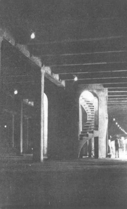
The concrete for the beams, columns, side-walls, and floor, was a 1:21⁄2:4 mixture, crushed sand and stone being used throughout. In the roof slab the mixture was 1:2:3.
The whole of the concrete work of the reservoir was completed in 6 months, by the Company's own administration, and the reservoir was first put into service a few days after the great flood of August 27th, when the Estanzuela supply main, crossing the Santa Catarina River, was partly destroyed. Since that time frequent examinations of the inspection pit, which is connected by a pipe to the rubble drains under the floor, have never revealed the slightest leakage.
Lay-Out of the Reservoir Roof and Grounds.—The Company owns about 111⁄2 hectares of land, which includes that occupied by the reservoir and its surroundings, and as this property is in an attractive situation, commanding fine views of the Sierra Madre Mountains, the whole of the works have been given a pleasing architectural character, and the grounds laid out to form a public park for the citizens of Monterrey.
Fig. 14.—Sketch Plan Of Lay Out At Obispado Reservoir. Larger.
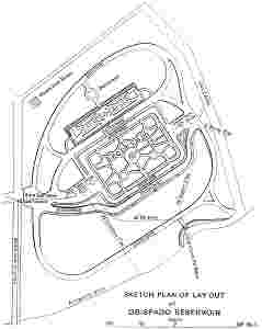
The general plan of the scheme is shown by Fig. 14 and Fig. 2, Plate XVIII. The roof, which has an area of 1 hectare, has been laid out with walks and grass plots, and the surrounding embankments have been converted into driveways. Above the reservoir a small plazuela of 1⁄2 hectare has been laid out with a space above it for a band-stand. The whole of the ground has been encircled with carriage drives, on which it is the intention to plant shade trees. The lay-out of this land also embraced the scheme for protecting the reservoir by draining the surface-water away to the irrigation ditches.