Main Sewerage System.
Reading edition
The Company's obligations, as far as drainage is concerned, were limited to the removal and disposal of sewage, no provision being required for storm-water, which is allowed to find its way to the natural watercourses. Apart from that fact, however, the best system for a city like Monterrey, where rainfall for many months at a time is very scarce, is the strictly "separate system." In the design advantage was taken of the natural topography of the drainage district, which is almost an ideal one for a gravitation system of sewers, the general fall in all directions being northeast; it was also in this direction that the best available land could be obtained for disposal purposes.
Plate XX.—Diagram Of The Main Sewers Of Monterrey. Larger.
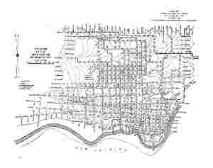
Plate XX shows in skeleton form the general lay-out of the sewers. Two drainage districts are arranged, divided by Calle de Washington, which may be regarded as practically the center of the city, and each of these districts has an independent main collector connecting to the outfall sewer at the northeast extremity of the city.
The system has been designed so that extensions may be made and may cover any part within the city limits; the main collectors are large enough for the whole area when fully built up.
The sewers are designed on a very liberal basis, namely, on the assumption that when flowing half full the quantity to be dealt with will be 380 liters per capita per day, with a maximum rate of flow of 200 per cent. It was assumed that each house would be occupied by 7 persons and have a frontage of 121⁄2 m. The minimum velocities in the sewers, when running full, vary between 0.91 and 1.5 m. per sec., with the exception of a few blocks.
The minimum size adopted was 24.3 cm. (8 in.) in internal diameter. The sewers of diameters between 24.3 and 50 cm., are 0.91 m. (36 in.) long, and are of salt-glazed vitrified clay, imported from San Antonio, Tex.
Table 12 gives the details of the length of the various sewers laid.
TABLE 12.—Length of Sewers.
Diameter:Kind.Length, in meters.
cmin.
24.38Fire clay38,332.85
25.410"16,400.69
30.512"7,953.15
38.115"4,850.56
45.718"2,023.40
50.820"1,450.53
55.922Reinforced concrete tubes, 6.9 cm. thick3,134.20
61.025Reinforced concrete tubes, 7.6 cm. thick357.40
68.627Brick and concrete484.05
76.230Brick and concrete662.69
———
Total75,649.15
The greater number of the manholes are of brickwork, 23 cm. thick, and have concrete inverts. They have a diameter of 1.2 m., which is reduced to 0.61 m. at the top, and each is provided with a heavy cast-iron frame and closed cover weighing about 190 kg. There are 521 manholes, and they are placed at every block and on long lines about 80 m. apart.
Fig. 16.—Standard 300-gal. Flush Tanks. Larger.
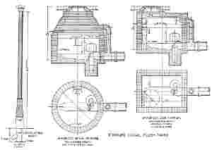
The sewers are flushed with 15-cm. (6-in.) automatic flushing siphons of the Miller pattern with 20-cm. (8-in.) discharge pipes. There are 278 of these siphons, and they are placed in flush-tanks (Fig. 16) built of brickwork and plastered with 1:1 cement mortar. Their capacity varies from 800 to 1,200 liters, and they discharge from 221⁄2 to 281⁄2 liters per sec. They are timed to flush once in 24 hours.
The system is at present ventilated by 23-cm. (9-in.) steel ventilating columns (Fig. 16), with ornamental cast-iron bases. There are 220 of these columns. Most of them are 7.85 m. above the level of the edge of the sidewalk, and are connected to special 15-cm. branch pipes leading from the sewer on the outside of the flush-tanks. In the center of the city they are provided with extension lengths, giving a total height of 12 m.
Table 13 gives the particulars of the average distributed cost of laying the 75.6 km. of sewers.
TABLE 13.—Average Cost, Per Linear Meter, for 75.6 Km. of Sewers, for Materials and Labor Complete.
Kind of Sewer.Internal Diameter of Sewers. Cost of materials including 10 cm. (4 in.) branches every 41⁄2 m. Pesos.Earthwork and Labor: Total cost of sewer complete per linear meter.
cm.in.Average depth of sewer m.Cost of excavation, including back filling, removing surplus, etc. Pesos.Cost of labor in laying (including hauling, etc.). Pesos.
Fire clay 24.3 8 2.00 2.10 3.46 0.21 5.67
" 25.4 10 2.78 2.25 3.97 0.2625 7.0125
" 30.5 12 3.64 2.50 4.705 0.305 8.65
" 38.1 15 6.14 2.75 5.50 0.4375 12.0775
" 45.7 18 8.80 3.00 6.745 0.645 16.19
" 50.8 20 11.30 3.50 8.275 0.815 20.39
Concrete 55.9 22 5.93 3.50 9.19 1.325 16.445
" 61.0 25 7.30 3.75 11.245 1.685 20.23
One brick thick on concrete foundations 68.6 27 7.17 3.75 11.735 3.93 22.835
76.2 30 7.925 4.00 14.53 4.515 26.97
Fig. 17.—Sketch Showing Disconnecting Trap On House Drain.
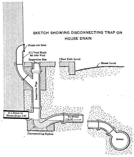
The house connections are chiefly of 10-cm. (4-in.) pipes, laid on a minimum gradient of 21⁄2%, from oblique branches on the sewer to siphon intercepting traps near the house, as shown by Fig. 17. From this trap a 10-cm. fire-clay inspection pipe is carried up and capped at the sidewalk level with a cast-iron box having a locked cover. From this inspection pipe a branch is connected to a cast-iron fresh-air inlet, in most cases set in the wall of the house, the inlet being 30 cm. above the level of the pavement.
Effect of the Flood on Sewers.—The flood of August 27th and 28th, 1909, partly destroyed one of the main collectors, which was laid along the banks of the river and encased in concrete. This has now been relaid farther north, and out of the way of any future floods. The total length of the new sewers replacing those damaged amounts to 1200 m., and they vary in internal diameter from 20 to 55.9 cm. (8 to 22 in.).