THE LATHE AND ITS USES.
Reading edition
The Lathe has now for many years been steadily making its way from the workshops of our leading artisans to those of the amateur and lesser stars of the mechanical world. This is but the natural result of the various additions and improvements which have been introduced into its construction from time to time. The unworkmanlike and clumsy tool of olden days has long since been superseded by one of admirable finish and perfect aptitude for its designed uses; and now that its construction is no longer dependent upon the skill of the workman alone, but upon machinery moving with the precision of clockwork, the fitting of the various parts is accomplished with the greatest ease and certainty. The sale being thus extended, the price has considerably diminished—the monopoly enjoyed by one or two makers no longer exists; and there are few of a mechanical turn of mind who cannot now provide themselves with a lathe suited to their requirements.
Nevertheless, the adepts in the art of turning are by no means so numerous as might be expected, and, among amateurs especially, it is rare to find work executed in first-rate style by simple hand tools requiring skill and practice in their use, so that it not unfrequently happens that a workman who can turn out exquisite specimens of ivory carving and ornamental lathe work, is but a fourth-rate hand with the gouge and chisel.
But however beautifully executed such ornamental work may be, the credit is rather due to the tool than the workman, and a well turned box with accurately fitting cover may bespeak more skill in handiwork than the above elaborately designed specimen.
Moreover the one requires lathe fittings, which are not always to be had unless the purse is well filled, whereas the general mechanic (amateur or professional) can provide the tools needed for the other; hence we propose first of all to give some practical hints on plain hand turning of wood and metal. The ordinary form of foot lathe is well known and requires no special description, it is represented in the frontispiece of this volume. There are, however, certain points of detail in its construction, to which it is necessary to direct the reader's attention.
First and foremost comes the mandrel, of which there are several patterns, according to the special purpose for which the lathe may be intended.
Now of whatever form it may be made this is the essential part of the lathe, and must run with the utmost truth in its bearings. Imperfection here will be imparted to all work executed upon it, and accuracy in this part alone will make up for any slight defects that may occur in less important parts of the machine.
For ordinary work in wood alone or in brass the best form is represented in Fig. 1.
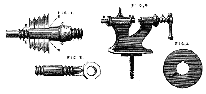
Figs. 1,2,3,4.
The part a, b, should be cylindrical, with a feather let in to fit a slot in the pulley shown in Fig. 2. This pulley, whether of hard wood or metal, is thus slipped on the mandrel as far as the collar d, d, and a nut e, screwed up tightly at the back of it, fixes it securely in its place, from which it may be moved if requisite and replaced without fear of being out of truth. This cannot be done if the mandrel is squared at a, b, and the pulley driven on with a hammer, as commonly done by inferior workmen. The part c, is made conical, to fit a hardened steel collar of similar shape. The angle of this conical part is of some importance, as if it is too small the mandrel is apt to jam and stick tight in its bearings. 35° will be found to work well. With regard to the length of this conical part, opinions differ considerably, but it must be remembered that friction is independent of the extent of the bearing surfaces and depends on the force with which they are pressed together (in the present case it depends on the tension of the lathe cord and the weight of the material to be turned), so that a tolerably wide margin may be allowed in this matter. Practically the question is decided by the thickness of the casting of the poppet head, which is regulated by the required strength and size of the lathe. The collar is sometimes of hardened steel, sometimes of brass. The latter would theoretically cause less friction than the former, but practically nothing can beat a well finished collar of hard steel. Collars of this material made by the original Holtzapffel two generations back are now as good as ever, perhaps even better. The centre, which screws up against the left-hand end of the mandrel, should be of the form shown in Fig. 3—a plain cylinder with a screw cut at each end to receive clamping nuts. The central part is rather larger than the screwed parts, and passes truly through the poppet head. This form is much better than a simple screw with points, as the latter is not likely to keep the line of centres in being screwed up into its place.
It will be found of great convenience to have the screw on the nose of the mandrel (and indeed all screws about the lathe) of standard Whit worth pitch, as taps for the chucks are thus readily obtained, and nuts and screws of the various sizes may be also procured to remedy breakages and losses. Upon this subject, however, we shall have occasion to treat more fully when we pass from the description of the lathe itself to the work that is to be accomplished by its aid.
The only form of back poppet that need be particularised is that made with cylinder and leading screw. The simple pointed screw passing through the lathe head tapped to receive it, not only requires no special description, but it is only calculated for lathes of the commonest design, as it is seldom that the line of centres is accurately maintained by the point at every part of the revolution of the screw. Moreover, the latter soon works loose in the poppet, and for anything like accurate work becomes speedily useless. The cylinder and pushing screw is indeed far superior to the form just alluded to, and where cheapness is an object it has its advantages over the first-named and best form. It is represented in Fig. 4. The cylindrical part is shown at B, and may have at one end the usual point, and at the other a small conical hole or hollow centre. It may then be reversed in its bearings at pleasure, or other cylinders with different shaped ends can be substituted, as may be found convenient. Of course the pushing screw A is for the purpose of advancing the cylinder, which is clamped by the small screw at C. The cylinder and leading screw are shown in detail in Fig. 5, which is the poppet head bored throughout to receive the spindle or cylinder A. At the right hand this bore is enlarged to form a recess, B, to receive the head of the leading screw, C. This screw is generally made with a left-handed thread, so as to withdraw the back centre when turned from right to left. The spindle A, A is bored, and a left-handed female thread is cut from end to end—this however is turned off at the place destined to receive the movable point or centre, and a hole slightly tapering is cut, or if preferred a cylindrical hole is made and tapped for the same purpose. The spindle has also a slot cut from end to end, into which a screw enters from the poppet, preventing the spindle from turning round while the internal screw is revolving by means of the small wheel and handle fixed to its right hand end. The spindle is now put in its place, the screw inserted and turned till the head or flange, C, rests in the recess before mentioned—a flat plate, F, is then attached to the back of the poppet by three or four screws, the head of the leading screw passing through its centre; the small wheel is then attached and the whole is complete.
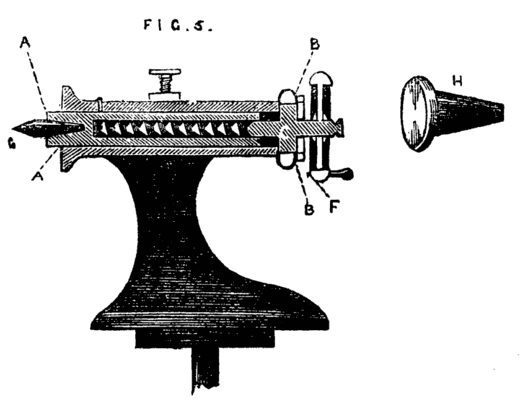
Fig. 5.
It is evident that by turning the wheel the internal screw is put in revolution, and as it is prevented by its flange from assuming any motion in the direction of its length, the movable cylinder will instead be withdrawn or thrust forward.
This form of poppet is the best that can be adopted and is of general use in all first-class lathes. In addition to the movable point g, a flange similar to H should be fitted. This will be found of great use when the lathe is used for drilling, the piece of work resting against it, while the pressure is regulated by the leading screw.
There are, in addition to the flange and pointed centre, other pieces of apparatus that can be substituted, as occasion may require, and these will be hereafter described in this series. With regard to the common rest for hand turning a lengthened description is unnecessary. The T or tee should for wood turning be of the form shown in Fig. 6 at A. It is often made as B, which is a very inconvenient pattern, as the cross piece on which the tool rests cannot be advanced sufficiently close to the work if the latter exceeds a diameter of two or three inches. For metal turning the top of the rest should be flat, and about one inch broad, as the heel of the hook tools used for turning iron must be able to take a firm bearing upon its surface. Sometimes a plate of brass is riveted on the flat top, as the tool takes a firmer hold on this metal, and when the latter becomes defaced and channelled it can be renewed without the cost of a new casting in iron. The turner should be provided with two or three tees for metal and for wood,—one may be long enough to have two legs and require two sockets, as shown at C. This is convenient in turning long pieces of wood,—a very short tee, not more than an inch in length, should also be provided, and if one tee is specially kept with a very level and smooth edge, it will be found of great advantage in chasing screws—indeed the latter work can hardly be managed at all if the top of the rest is damaged and uneven. The next part requiring description is the boring collar, without which even a hand turning lathe can hardly be considered complete. This boring collar is intended so to support one end of the work, instead of its being held by the back centre, as to enable the workman to get at the end of it for the purpose of drilling it. Suppose for instance the work in hand is a tool handle, and that it is so far finished as only to require the hole for the reception of the tang of the tool. If this is bored by hand with a gimlet, it is seldom that the hole will be truly in the axis of the piece, but when this is done in the lathe by the help of the boring collar the bore will be truly central, and the tool when in place will fall in the same line with the handle. This will conduce to the correctness of the work in hand more than the amateur or other workman might suppose, and a row of tools thus truly handled and in good condition generally bespeaks an efficient and careful artisan. There are several plans for boring collar of nearly equal efficiency, and we shall describe one or two of the most common, and also one invented by the author, and which, if carefully made, is of great service. Fig. 7 represents a poppet head, B, which is but half the height of the other poppets of the lathe—a side view of this is shown at B, Fig. 8. Near the top of this poppet is a hole through which passes a bolt C, by which and its nut the circular plate A can be securely clamped in any desired position, as it revolves freely on the bolt as a centre pin. This plate is bored with a series of conical holes, which are so arranged that their respective centres will be in a line with the centres of the mandrel when any one of them is brought into a position corresponding with the line c, c. The hole thus brought into position for use (having been selected according to the size of the work to be bored), takes the place of the back centre; the end of the work rests in the cone, which is greased or soaped to reduce friction, and the rest being fixed at the other side of the boring collar, the drill can be readily used, and the bore afterwards enlarged if necessary with any convenient tool. This boring collar is generally made of iron, but a substitute of hard wood will frequently serve the purpose, and can be made by the amateur, who may be unable to obtain one of more durable material. If made of wood the best unguent will be soap or black lead, such as is used for grates, or a mixture of the two. This black lead or plumbago (it has no lead in its composition) will always be found serviceable where wood works upon wood, and also to give a smooth surface to wooden patterns for casting.
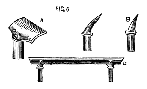
Fig. 6.
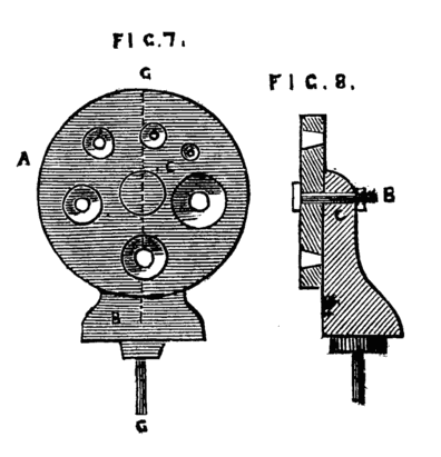
Figs. 7,8.
Where cost is an object, a simple substitute for the boring collar is frequently made by the ordinary workman by a piece of board one inch thick, shaped like Fig. 9, with a single hole of the size most generally required; and the work is then fitted to the boring collar, instead of the latter to the work. In turning tool handles, for instance, where a few dozen are required all of the same size, or nearly so, a device of this kind, which can be made in a few minutes, is sufficiently effective. This form has been modified in two ways, and either will be found convenient. In the first, the conical hole is made of the largest size likely to be required, a set of boxwood plugs are then turned to fit this hole and are themselves bored in a similar way to suit various sizes of work. The form of these plugs is shown in Fig. 10, which is a side sectional view, and at B, where the same is shown in perspective. Two small screws or pins b, c, Fig. 10, fitting into the holes a, a, Fig. 9, prevent these flange-shaped plugs from turning round in the board as the work revolves. The pattern of A, Fig. 9, may be varied, and is better made of hard wood, and of a form which will afford a good bearing upon the lathe bed.
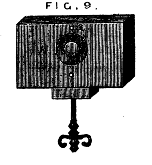
Fig. 9.
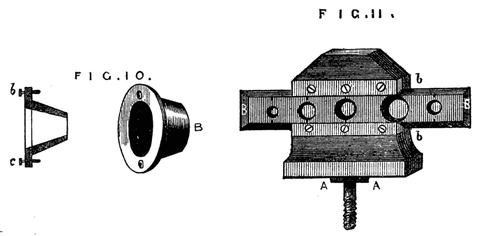
Figs. 10,11.
The second modification is more difficult to make, but equally effective. It is shown complete in Fig. 11. This form, arranged by the writer, has many advantages over the two last-named, and is very serviceable. A is the poppet, of the full height of the ordinary lathe heads, or a couple of inches higher. B, the slide forming the support of the piece to be bored. The form of the poppet without this attachment is shown in Fig. 12. If for nice work it should be made of metal and the face of it planed, but for general purposes hard wood will suffice. b, b, Fig. 11, are two pieces of brass forming a groove or guide in which a slide B, with dovetailed edges is fitted to work. This slide is bored, like the ordinary collar, with conical holes of different sizes, and should be made of metal and planed on back and edges. Over each hole is a mark, and this is to be brought to a similar mark on the face of the poppet. The plate is then clamped in position by a screw at the back of the poppet. One or more of such slides may be fitted at pleasure, and in case of wear or damage these are the only parts requiring to be renewed.
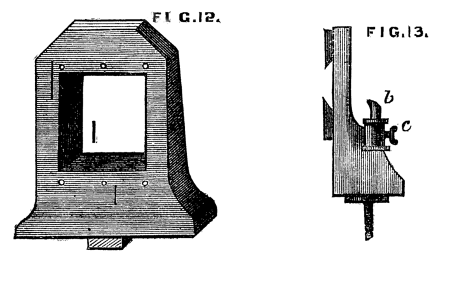
Figs. 12,13.
It is a good plan to arrange a socket and tee of a rest as b, c, Fig. 13, at the back of this boring collar, especially as the position of the tool will be always the same, so that the rest may be a permanent part of the poppet. There is sometimes a difficulty with the ordinary form of boring collar in advancing the rest T sufficiently near the work (the foot of the poppet, and that of the rest preventing it, by coming in contact.) There is another modification of boring collar, forming at the same time a guide for the drill, which in slender work, where the tool is long and fine, becomes almost a matter of necessity.
This consists in making such a guide cone as mentioned and shown in Fig. 10, B, but with a continuation containing a smaller hole for the drill, as Fig. 14. Both this and the other shorter cones above-mentioned may be made to screw into the poppet A, Fig. 9, instead of being kept in place by the pins at a, a, of that figure. In that case however the hole in the poppet must be cylindrical and only used as a support for the cones themselves. In addition to the use of these boring collars already alluded to, they serve for the purpose of turning up the points of screws like those of lathe centres. These are first formed between centres with carrier chuck, the back poppet is then removed and the extreme point fitted through one of the holes of the boring collar and the marks of the centre turned off.
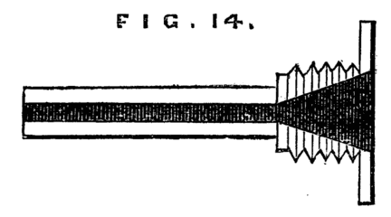
Fig. 14.
Another useful adjunct to the lathe is the back rest for supporting long and slender articles, which would otherwise bend under the pressure of the tool. The ordinary and simplest form is shown in Fig. 15, and this is of general use with brush handle makers and others whose work is confined to a few sizes and shapes only. A better form is shown in Fig. 16. A support of wood or metal shaped like A is clamped to the lathe bed. Through the upper part the slide B passes and is wedged up so as to support the work—or the socket of a lathe rest may be arranged to take the upright part A, which must then be rounded, as shown at C.
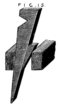
Fig. 15.
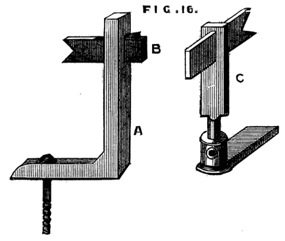
Fig. 16.
A modification of the latter, communicated to the English Mechanic, is shown in Fig. 16A. Its construction and mode of application is sufficiently evident without a detailed description. Fig. 16B is another form made in metal. It consists of two similar plates with a triangular opening A, through which the work is passed, and which has an oval slot D, by which the apparatus is secured to the short poppet of the boring collar. Between the two plates slides a third, partly visible at C, which can be clamped by a screw at B, this screw also serving as a stud by which the plate may be moved. The work is allowed to take up its own bearing in the triangular opening as it revolves in the lathe. The clamping screw of the poppet is then secured, and the centering thus made certain. The plate C is then made to descend so as to touch the work, and clamped in that position. This is a very good central support for long slender articles.
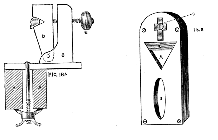
Fig. 16A,B.
There is a plan practised by German turners by which the back rest is in a measure superseded, and which may be mentioned here. It is simply the peculiar method of using the left hand. This is placed on the piece to be turned so that the fingers partly encircle the work while the thumb rests in the hollow of the gouge, or upon the end of the tool. The fingers thus form a back rest and keep the work pressed against the cutting edge, which is further steadied by the thumb. As the tool traverses the work the left-hand accompanies it, and with a little practice a ramrod or similar long and slender article may be readily and accurately turned. This position is shown in Fig. 17, and though the novice will find it difficult to work thus, it is well worth the trouble of mastering, as the method once acquired will be found of very great service.
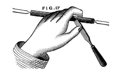
Fig. 17.
We have now described more or less in detail the principal parts of the lathe as adapted for hand turning. Before we dismiss this part of the subject, however, it will be necessary to say a few words respecting the bed and lower fittings, the flywheel, treadle, and their adjuncts.
Beyond question the iron bed, planed as it now is at a moderate price, by machinery, is the best that can be adopted, especially if it is intended eventually to fit up the simple tool with slide rest and superior apparatus. Nevertheless, the pocket must in this case also frequently decide the question of material. If wood is preferred by necessity or otherwise, it should be hard wood, beech, or Spanish mahogany, unless it is proposed to plate the surface with iron. This latter plan costs little and, besides stiffening the bed, it prevents the wear and tear caused by the constant shifting of the back poppet and rest. A flat strip of iron one inch or an inch and a half wide can be picked out from the stores of any village blacksmith straight and level as it came from the rolls of the manufacturer. Selecting a piece of the required length and breadth, the eighth of an inch thick or rather more, the purchaser will have holes drilled and countersunk at intervals of nine or ten inches, to receive ¾-inch screws. These strips will have to be laid upon the top of the bed, at its inner edges; they need not be let in flush with the surface unless appearance is studied.
They must then be screwed down firmly, and by means of a file worked by both hands up and down their length (not across them) a good surface may be readily obtained. If the iron is let into the bed this filing will abrade the wood work, which is the reason why we prefer screwing it on the surface. This method produces a very excellent and durable lathe bed, and it will be free from much of the tremor which is so disagreeable while working upon a lathe entirely of cast iron unless the bed of the latter and the standards are more substantial than is usual with small lathes.
The standards supporting the axle of the fly wheel and bed may in like manner be of wood or iron. Even when the bed is of iron these may be of hard wood, although it is customary to make them of the same material as the bed. If of beech, oak, or mahogany, as in some of Holtzapffel's best lathes with iron beds, the tremor before alluded to will be considerably lessened. Iron is nevertheless very neat, and is quite the fashion with the majority of makers, but is too often faulty in respect of solidity.
The standards as a rule are too slight, an elegant pattern being studied to the sacrifice of substance and weight, The bed and stand of a lathe cannot be too strong and stiff.
Respecting this matter of stiffness and solidity we seldom find it sufficiently considered, and, even with practical workmen, a defect in this particular is more frequently acknowledged and put up with than remedied, although the comfort of a steady lathe is beyond question, to say nothing of its superiority when good workmanship is studied (as it always should be). The old French lathes made in the form of a thick table with four stout legs, forming the bed and back-board, are by no means to be despised as patterns; and instead of the usual method of making but one standard at end of the bed, there can be no question that two additional ones add considerably to the stability of the machine.
The fly wheel should be sufficiently heavy and have three speed grooves on the rim and two additional ones to produce a slow motion, which is required for turning metal. The latter may be worked with ease in this way when the article to be turned is small, but if heavy work is likely to be encountered the back geared lathe, to be hereafter described, must be substituted, and the slide rest will then also replace the hand tools. The crank axle is generally supported by two centre screws, the points being hardened, and also the ends of the axles, which are accordingly made of steel, and the holes for the centre screws neatly drilled and countersunk.
This is however not the most perfect method, and as we are speaking of better class lathes, as well as those of more common and cheaper make, we must by no means omit to speak of a very superior way of fitting the crank axle. The latter must be turned at both ends, the wheel bored and slipped on, and keyed in its place.
Two wheels of brass about two inches diameter, must then take the place of the centre screws. These are called friction wheels, and they must be placed sufficiently near each other to support the end of the axle between them, as shown in Fig. 17B, a and b. A pair of these must be thus fitted to each standard, and after the axle is placed in position a third may be placed above it to prevent the lathe cord from lifting the axle out of place by its tension. The axle and friction wheels will thus work together with an exquisitely smooth rolling motion—there will be no tendency to thrust the lathe standards apart as must result from tightening the ordinary centre screws, and the friction of the axle on its bearings will be reduced to a minimum. Any person acquainted with the use of the lathe may readily fit up these friction wheels, and the time and trouble so expended will be amply repaid by the superior ease with which the lathe can be used. We may say the same of the chain and eccentric, which can replace with similar advantage the crank and hook in ordinary use.
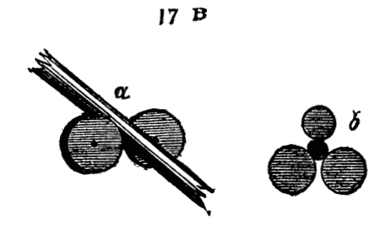
Fig. 17B.
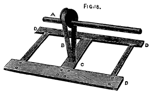
Fig. 18.
For the latter the following arrangements are necessary. A is the eccentric keyed to the crank axle, and may be either in the middle of the same or, as in Muir's patent lathes, at one end outside the standard. Around it passes the endless flat chain B (known as crank chain). This also passes round a roller in the treadle shown at C. This chain does not act as a mere link, but when the lathe is in action it moves round and over the eccentric and treadle roller. The motion of the whole is smooth and regular, and, what is almost as important, noiseless. In Muir's and other lathes the crank chain is used without the eccentric, being applied to the crank instead. Perhaps there is not much to choose between the two, but no one who has studied the eccentric and observed its exquisitely gentle and smooth motion in an ordinary engine can have failed to be struck by these valuable qualities. It must however be remembered that its throw is half that of a crank of the same eccentricity and the latter will have the advantage in power size for size.
In whatever position the lathe may be set up let the rise of the treadle be moderate. It is exceedingly disagreeable to work at a lathe where the rise of the foot board is so great as to bring the knee into contact with the lathe bed, a consummation not infrequent in country made ones.
This is only to be escaped by giving up a certain portion of power. Let A, B, Fig. 19, be the line of the treadle when at rest; c, the crank. To gain power we should let part A, E, be longer than E, B, as in the sketch. But let this arrangement be made, and when the crank is at its highest point, the line G, B, will show the position of the treadle and foot board. Hence this kind of leverage is not practicably available to any extent, and the length taken from foot board to link may with advantage be even less than that from link to the axle on which the treadle works. In lathes, of all machine tools, it is essential that the workman should be able to stand easily, that the movements of the leg and body should not be communicated to the tool, the play of the treadle and such items of detail being of more consequence than might at first sight appear, and any method tending to diminish friction, vibration, and noise is well worth consideration in planning this machine.
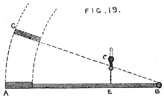
Fig. 19.
We may now suppose the reader the happy possessor of a well made foot lathe, long or short in bed, high or low in poppet, according to his need, but, of whatever size, carefully made and firmly fixed in a well-lighted place, and if possible on the basement floor—an upstairs workshop is objectionable owing to the certain vibration of a boarded floor. He will now require certain chucks and tools, many of the former of which he will have to make for himself.
Chucks.
No lathe can be considered well fitted until it is supplied with a large number of chucks, by which strange term are signified the various appliances for fixing to the mandrel the article to be turned. When it is considered how varied are the forms which present themselves to the turner, it may readily be conceived that much ingenuity has to be exercised in contriving methods for mounting his work in the lathe; and when in addition to variety of form, variety of size has to be taken into consideration, it is plain that a large assortment of chucks is a necessary item in the workshop of the turner. A vast number of these chucks are of necessity made of wood, as required, and such wooden ones are altered from time to time to suit different-sized work, till they eventually become so completely used up as to be only fit for the fire. In addition, however, to these, there are certain chucks of metal (chiefly brass or gun metal) which should always be ordered with a lathe, or fitted to it before any work (even the making of wooden chucks) can be satisfactorily accomplished. The first of these, is represented in Fig. 20, the part A, screws to the mandrel; while the work is attached to the taper screw B. The use of this chuck is to hold short pieces or flat discs, which allow of a hole in the centre and require to be turned on the face. It is only used for wood-work. This is the chuck to be selected when it is desired to make a wooden chuck. A piece of sound wood being chosen of the requisite size, and roughly rounded by the axe or chisel, a hole is made in one face by a gimlet rather smaller than the tapering screw. The piece is then firmly screwed to the latter, the opposite end dressed with gouge and chisel, and the rest being placed across the end, a hand-drill for wood is brought to bear upon the piece. The hole thus made in the centre is then enlarged by any convenient tool until its diameter is only a little less than that of the screw cut on the lathe mandrel. An inside screw tool is then made use of to cut a thread of the same pitch as that of the mandrel, or a tap of similar size and pitch screwed into it (the former is the best but most difficult method to a novice), the piece detached from the taper screw chuck, which is removed, and the wood attached to the nose of the mandrel on which it may now be accurately fitted and finished to the requisite form and hollowed out or otherwise, as may be necessary. Numberless articles may be in a similar manner turned upon the above chuck such as the bottoms of candlesticks, ring or other stands, bread-platters, small wheels, and so forth; it may therefore stand as number one of these adjuncts to the lathe.
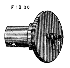
Fig. 20.
Fig. 21 is the face plate, another most serviceable chuck of almost universal application in such work as surface-turning and boring, and where a hole in the centre is inadmissible. To this belong various dogs or cramps, a few forms of which are shown at a, b, c, d. These hold the work firmly down to the surface of the plate, being tightened from behind by screw nuts. It will be seen that there are four slots and numbers of holes in the face plate, some of the latter being tapped for screws. These slots and holes may be increased in number, and some of the latter may be square instead of round, and the cramps may be of all shapes and sizes, because sometimes it may be required to hold down a flat piece of brass the eighth of an inch thick only, and the next job may be to hollow an irregular block of wood of three or four inches in thickness, or it may be necessary to bore out the boss of a wheel, or to turn the rim—all of which, and a hundred others, are cases in which the aid of the face plate will be in requisition.
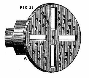
Fig. 21.
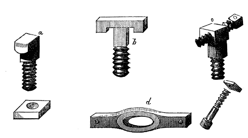
Fig. 22 is the chuck specially used for turning rods of metal. It consists of two parts, the body A, which screws to the mandrel, and the piece B, which passes through a slot and is clamped by a small screw at one side c. To these must be added the carrier which is of such forms as A1, B1, C1. Above is shown a rod of metal to be turned with this chuck in position for use. Of this we shall have to speak again when we arrive at the subject of metal-turning. There should be several sizes of carriers kept in stock, from ¼in. in the largest part of the ring to 2in. or 3in., or even much larger for heavy work. The amateur will, however, scarcely need these larger ones. The usual method of making the wood-holding chuck for work that is to be also supported by the back centre, is to have a socket cast like Fig. 23, C, with a central hole to take the fork A, which is held in place by a set screw. This socket is useful for other purposes as it will hold short pieces of iron to be turned, but the fork is far inferior for general work to the piece b; this is made of iron, and the end of the cross (against which the wood to be turned comes) is sharpened but must not be too sharp. The end of the piece of wood has then two saw-cuts made at right angles to each other into which the sharpened edges of the cross fall, Fig. 23 D, and the whole will turn together without any chance of slipping. It often happens, when the ordinary fork is used, that if the tool chances to hitch in the work, the latter is either thrown quite out of the lathe, or the centre of the fork retains its place, while the other two points slip and score the work. This can never happen with the form B, which is the most reliable pattern that can be devised for work of this nature.
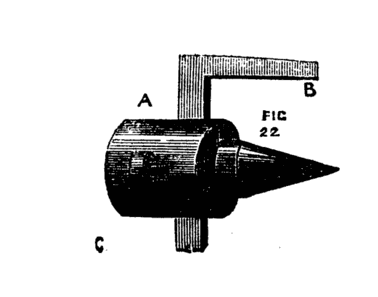
Fig. 22.
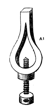
Fig. A1.
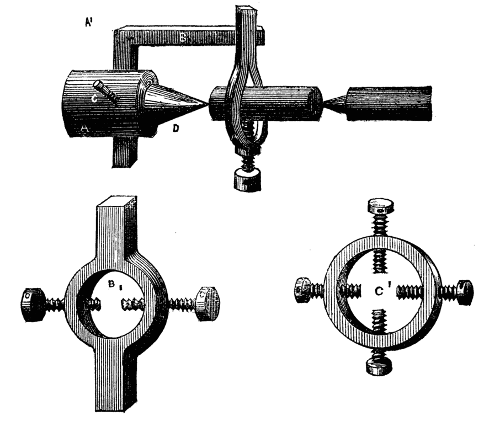
Figs. B1, C1.
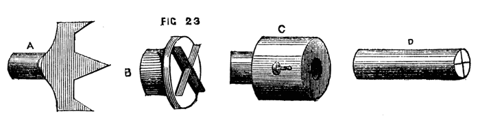
Fig. 23.
Fig. 24 is to some extent self-centering. A piece of wood hollowed out conically has three nails, or three-square saw-files so placed within the cone as to present three sharp edges inwards. Any piece of wood, if not too hard, will, if placed with one end in the chuck, while the back centre is screwed against the other, centre itself in some part of this cone, and, being at the same time held by the three sharp edges, will necessarily revolve in the chuck. There are many cases in which even in this rough form such a chuck will prove useful; but if it were cast in metal and the three edges formed by slips of steel, and the whole accurately turned, it would be a very efficient and good self-centering chuck. In its more common form it is largely used by the turners of mop and broom handles, who work rapidly and cannot afford to waste time in chucking their work. With the above, the lathe, if worked by steam or water power, is not even stopped,—the screw of the back centre has a quick thread, so that a single turn to or fro fixes or releases the work; and thus, one handle being finished, another piece takes its place in the chuck, is fixed by a half-turn of the back screw, and being set in rapid motion is turned and completed by a practised hand in a couple of minutes or less.
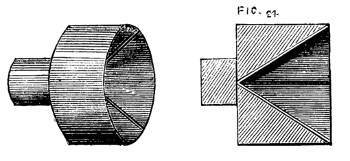
Fig. 24.
Fig. 25 represents another useful chuck, generally of boxwood, called the barrel stave chuck. It is turned conical, the largest part being towards the mandrel; it is then wholly or partially drilled through, after which saw-cuts are made longitudinally, as in the drawing. These allow a certain degree of expansion when a piece of work is fitted into it, and it is tightened round the latter by driving on a ring of iron or brass. This ring is sometimes cut with a coarse thread inside, and a similar thread being chased on the outside of the chuck, it is screwed upon the cone instead of requiring to be driven by blows of a hammer. One important use of this chuck is to re-mount in the lathe, for ornamentation by the eccentric cutter or other apparatus, any finished work that could not be readily chucked in any other manner, or to hold rings requiring (like curtain rings) to be turned on the inside. Such articles will, from the nature of this chuck, be truly centred at once; and their exterior parts will not be liable to injury, as they would be by being driven into an ordinary chuck hollowed out to receive them.
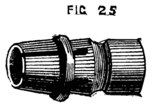
Fig. 25.
Another useful chuck for turning short pieces of metal such as bolts and binding screws, and which is in a great measure self centering is made of cast iron, and is usually called the dog-nose chuck, represented in Fig. 26. This is made with movable jaw hinged, as more plainly seen in B. The screw clamps these jaws firmly together, and any small piece of work is thus securely held. The centering, however, is not accurate, though sufficiently so for many purposes. The die chuck (Fig. 27) is accurately self-centering, and although somewhat expensive, is a valuable addition to the lathe. This chuck consists, first of all, of a socket for screw to fit the mandrel, and round flat plate of brass cast in one piece, as in Fig. 28. This must be carefully turned and faced in the lathe. Two pieces of iron or brass are then screwed to the face, as B, B, 28A, leaving a space between, the sides of which are to be truly parallel. These pieces may either be chamfered to form V-pieces, or may be rectangular on their inner edges; at C, C, a part of each is cut away, and the outer or back plate is also filed down to receive the small plates D, D. E shows a groove in which a screw lies, half of which has a right and half a left handed thread; this is shown in Fig. 29. It will be evident that if this screw is placed in the groove of the bottom plate, and its ends pass through the pieces D, D, which are screwed to the plates, it can revolve in its bearings, but will have no endwise motion; the collar F resting in a recess under the top plate D. This screw passes through a projection in the back of the pair of dies, which projection also goes into the same slot in the back plate in which the screw works when turned by the key (Fig. 27, B.) The above being nicely fitted, the dies moving evenly but stiffly in their places, the plain top is screwed on, keeping all firmly together. This plate has a long opening or slot (Fig. 27), through which the jaws of the dies and part of the screw are visible. The ends of the screw should not project, as any such projection is calculated to bring to grief the knuckles of the turner—a consideration worth attention in every form of chuck—the squared ends of the screw lie in a recess in the small plates, as shown in the section of one of these plates (Fig. 28X). Into this recess the key fits over the screw end; and by turning this the dies are simultaneously moved asunder, or closer together so as to grasp centrally as in the jaws of a vice, any small article, such as a screw or short rod of metal placed between them, A similarly contrived chuck is often used under the name of a universal chuck, for holding pieces of large diameter, and is very useful for taking pieces of ivory which have to be hollowed or otherwise worked, as will hereafter be detailed. In this case the jaws may be semicircular in form, as Fig. 30.
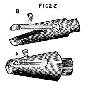
Fig. 26.
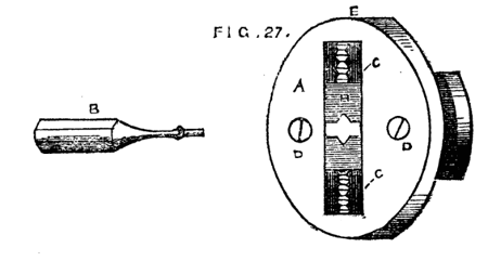
Fig. 27.
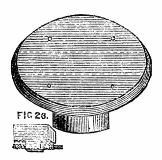
Fig. 28.
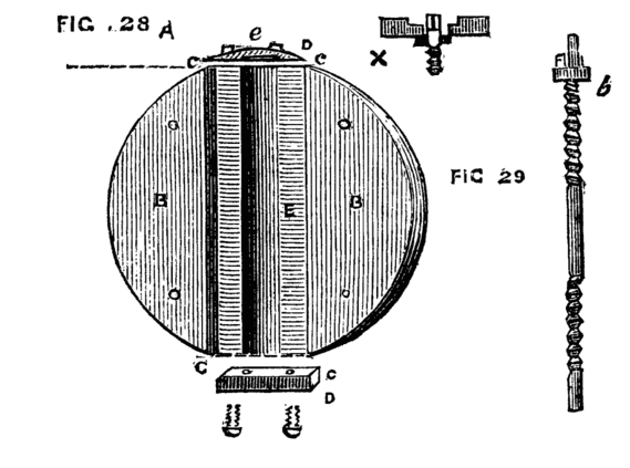
Figs. 28, 29.
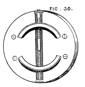
Fig. 30.
It is however, evident that these two chucks have a rather limited range. The first can only be used for small work, and the only case in which the latter can take firm hold all round the work is when the jaws are just so far apart as that they form portions of the circumference of one and the same circle. Practically they will hold the work tightly under an extended range of sizes, and they are thus of great use to the turner. The following is however more perfect in operation, from the fact that it has four jaws instead of two which meet concentrically. This may be made either with two long screws at right angles to each other, with right and left-handed threads to each, as in the die chucks, or more simply and, in some respects more satisfactorily, with four distinct screws, all of the same pitch, and all with squared ends of equal size, to allow of the same key being used to turn them. It is possible to use such a chuck as an eccentric chuck if desired, which is certainly a recommendation in its favour over those which work always concentrically. The face of this chuck is shown in Fig. 31. The ends of the four screws have a bearing in the small centre plate b, whilst the collars or flanges rest in a recess under the several plates c, c. The face of this chuck is graduated by each die, so that it is easy to set the jaws concentrically or to place one or more eccentrically to take in work of other shape than round or square. The jaws of this form of chuck are used for two purposes, either to hold work inside them like a vice, or externally. A ring, for instance, requiring to be chased on the outside is slipped over the jaws, which are then caused to recede from the centre so as to hold the work securely. If the latter does not run truly, one or more of the screws can be slackened, and the opposite ones tightened, or if the eccentricity appears to be in an intermediate part, two adjacent screws will have to be thus slackened and the others tightened. On the whole this is a most useful pattern of chuck.
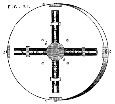
Fig. 31.
The following is a very excellent self-centering chuck now coming into extensive use. It has been noticed in more than one periodical. The description annexed is extracted from the pages of the English Mechanic. "The chuck hereby illustrated seems to be a very convenient form, easily adjusted and holding the drill securely. It is also well adapted for holding wire to be threaded. Every piece of which it is composed is of cast steel well hardened. It can be furnished with a shank to fit the hole for the centre, screwed on the spindle, or slipped on the centre. No wrench is necessary, the gripe of the fingers being sufficient to secure the shank of any drill. The inventor claims that he has used a one-inch drill, in tenacious wrought iron in one of them, receiving a shank of only three-eighths of an inch diameter without using a wrench."
Fig. 31A represents the shell of the chuck with milled bosses for the fingers. The core, B, is threaded and receives a steel wire spring which is inserted into the rear of each jaw, so that when relieved from pressure, the jaws open automatically.
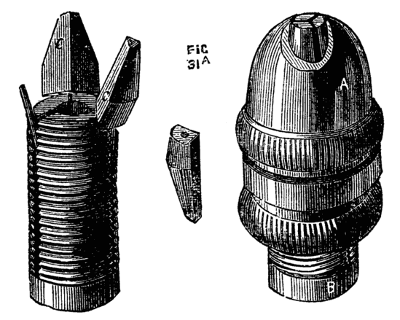
Fig. 31A.
With this brief explanation, the operation of the chuck can be easily comprehended. These chucks are made of two sizes, one with an opening of three-eighths of an inch, and the other of three-sixteenths of an inch, and they can be made of larger sizes. Patented by L. H. Olmsted, Stamford, Connecticut, United States America.
Another chuck of self centering design, has likewise appeared in the periodical above named, into which it appears to have been copied from an American paper.
The accompanying engravings illustrate some improvements in the arrangement of chucks which have been recently patented in this country, the inventors being Messrs. Smith and Haight, both of New York, U.S. The first part of the invention refers to an arrangement of adjustable chuck, by means of which tools and other articles of different diameters may be held firmly in the jaws of the chuck. Fig. 31B is a longitudinal view of the chuck, partly in section. The spindle, a, is fitted so that it may be inserted tightly in the mandrel of the lathe. On the front end of the spindle is a conical screw on which is fitted the cap, b; this part is formed with an opening at the front end, having three longitudinal slots in it. In each of these slots an adjustable jaw, c, is fitted, the inner part of which is threaded with a female screw, to fit the conical screw on the spindle, a. An outer casing d, encloses the front part of the chuck, and behind this is fitted a loose collar, which is screwed into the casing d, so as to connect the parts firmly together. By turning the cap, b, with the casing, d, and collar, in one direction, the jaws, c, are moved forward and project out through the openings, and they may thus be adjusted to grip a tool or other article of small diameter. The opposite motion of the cap causes the jaws to recede, and in this way they may be adjusted to grasp articles of different diameters.
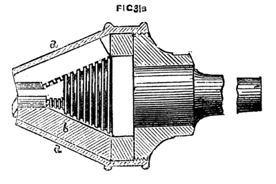
Fig. 31B.
Another arrangement of the adjustable chuck is shown in Fig. 31C, which is a front view, and Fig. 31D, a longitudinal section of the same. A, is the body of the chuck, the front part of which is formed with a rim or flange, in which are three radial recesses having fitted therein the sliding jaws, B. In the rear of each jaw is a bearing, in which is fitted a pin carrying a small lever, C, the front end of which is rounded, as shown in the section, and enters a slot made in the jaw, B; so that when the levers are moved outwards they cause the jaws to contract or move towards the centre. The back part of the body, A, of the chuck is threaded, and on this part is fitted a collar, D, and in front of this is a sliding collar, E, which is connected to the collar, D, by means of a pin which enters a groove formed in the latter. The sliding collar is prevented from turning round on the body, A, by means of a feather, which works in a longitudinal groove formed in the inner circumference of the collar. Three inclined planes, F, are formed on the periphery of the collar, E, which extend to the backward ends of the levers, C, so that by moving the collar to and fro, the jaws, B, are caused to contract or expand, according to the size of the article to be grasped. A short cylindrical block, G, made of a conical figure internally is fitted loosely within the chuck, A, and serves to centre the end of a drill or other short article, but may be removed when it is desired to pass a rod or other article through the body of the chuck. To provide for the easy turning of the collar, D, it is shown as fitted with a hand wheel, H. With this arrangement of the several parts, the jaws of the chuck readily adapt themselves to drill or bit shanks as well as to articles of parallel form, or of a tapered or irregular figure.
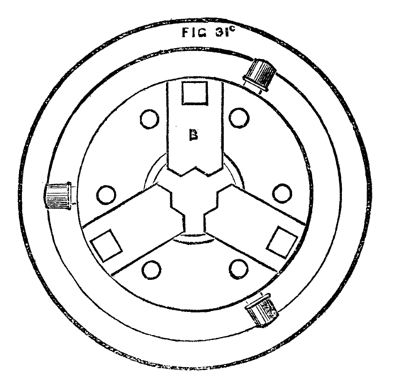
Fig. 31C.
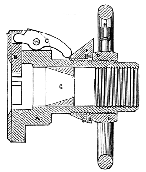
Fig. 31D.
The chucks last named belong to the class of compound or mechanical tools; and though their usefulness is beyond question, they need not be considered absolutely necessary, as the work which they are designed to facilitate can be and often is done without their aid. Indeed, success in the art of turning by no means depends absolutely upon the possession of expensive apparatus, and the amateur or mechanic will find the advantage of ransacking his own brain for the devising of divers makeshifts and off-hand contrivances—especially in this chuck-making department.
Among the simple expedients the following will be found well worthy of adoption.
A, Fig. 32, is a simple flange or flat brass plate with a boss behind, similar to a small face plate, and is to be turned up, drilled, and tapped to fit the mandrel. If the latter has a diameter of ¾ of an inch, a few of these brass pieces should be cast from a set of wooden patterns ranging from two to three or four inches across the diameter of the plate, and, after having been fitted to the mandrel and turned, four holes, countersunk for wood screws, should be made, as shown in the sketch. These are intended to do away with the necessity of boring out and tapping each individual wooden chuck. They can be readily attached to any piece of wood by four screws, and a few minutes will be sufficient to adapt the same to any required purpose. A flat piece of board, for instance, itself too thin, or of too soft substance to permit of its being attached to the mandrel in the ordinary way, can thus be made into a temporary face plate, or a ring cut out of it, or any desired operation performed upon it. Indeed, these socket pieces will be found serviceable on many occasions, and will do away with the necessity of a large set of cup chucks.
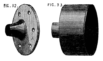
Figs. 32, 33.
A few of the latter, however, are very useful and will cost but little. The castings are sold by weight, and the turner will experience no difficulty in fitting and finishing them for himself. Fig. 33 is the form of these, and needs no description. The substance may be from ⅛ to ¼ of an inch, and need not be more, as that thickness will stand any reasonable shock caused by driving a piece of wood into the chuck, and it is always well not to overweight the mandrel with chucks of undue size or substance. The addition of three to six screws to one or two sizes of the cup chuck extends its usefulness. This form is represented in Fig. 34, A and B. In this case, the casting may be rather more substantial (¼ to ⅜ of an inch in thickness). The screws must be strictly radial, pointing to the centre of the circle, and their ends must be turned off or filed flat. Their heads may be squared to enable a key or pair of pincers to be applied, or round with a hole through them. It is better to make this kind of chuck with six screws—three in one plane, and three again between these in another plane behind them. In fitting a piece of work into the chuck, it will not at first be found an easy matter to make it run truly. The best way is to centre it as nearly as can be guessed, by means of the three screws nearest to the open end of the chuck, and then, placing the latter on the mandrel, set the lathe in slow motion and correct the eccentricity of the piece by means of the three inner screws. Even after this it is probable that a little alternate slackening and tightening of the different screws may be necessary; but a little practice will quickly enable the turner to set a piece of work in the true axial line of the mandrel without much difficulty, and the work will then be held very securely. Any short piece, such as the ring of an eccentric to be bored truly inside, may be held by the outer set of screws alone; but if such a piece of work as a small cylinder is to be bored, the six screws must be brought into action. Here let the hint given when speaking of projecting screws, be repeated, Beware of the knuckles, which are peculiarly liable to be damaged in making use of these chucks. The shirt sleeve or coat, moreover, does not always enjoy perfect immunity from similar danger, and both should be kept out of harm's way, not for their own sake only, but because the arm may be brought into violent contact with the rest if the sleeve should get entangled (the momentum of the flywheel being great, and therefore not to be checked entirely at any given moment). A single rap of the above nature is not a delightful even if salutary lesson to the novice.
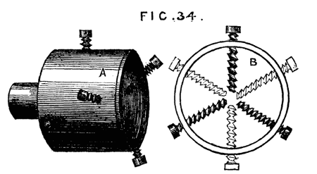
Fig. 34.
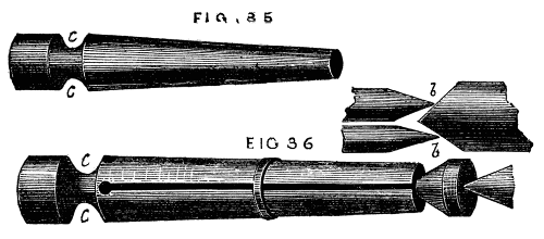
To hold rings and washers a tapering mandrel, Fig. 35, is used; and of these it is necessary to keep a few different sizes to suit different diameters. These may be made of iron or brass if for permanent use, but box or other hard wood is a ready substitute, and may be turned down for smaller work when the surface gets spoiled by use. The expanding mandrel, "Hicks' patent," which will be treated of hereafter, is a convenient substitute for the simple conical form here spoken of; and in manufactories where large numbers of mandrels have to be kept of various sizes, a great saving of time, money, and labour is effected by their use. For amateurs and artisans in a smaller way of business the simpler form is generally sufficient. A slight modification is here appended, by which the common form may sometimes be made more efficient in the holding a ring tightly while undergoing the operation of turning, and this can be made applicable to metal mandrels, though specially intended for wooden ones. Fig. 36.
Figs. 35, 36.
The mandrel having been turned conical (N.B., the angle of the cone must be small, so that the size will diminish very gradually from the largest end), the wood is divided by a fine saw, just as the chuck already described with the outside rings was sawn into segments, a conical hole having been first made at the smallest end, as shown in the section b, b. Into this a short cone of larger angle is to be fitted, against the end of which the point of the back centre will press, tending to drive it into the mandrel, which will thus be made to expand. The ring to be turned will prevent the mandrel from splitting by the wedge-like action of the plug, unless the said ring is of light substance, in which case this form must not be used. The work will, by the above method, be securely and centrally held and not liable to slip towards the small end of the chuck.
In the Fig. 36, a groove, c, c, is shown at the bottom of the saw-cuts. This should also be made round the boxwood spring chucks with rings, as it gives more freedom of expansion to the segments. With such a groove and the chuck itself completely hollowed out, the pressure of a strong india-rubber ring will be sufficient to hold work whilst being polished: and this will, when the latter is delicate, be even superior to the screwed rings, as the pressure will be more gentle and equable. India-rubber rings for this purpose must not be thin and flat, like those used for bundles of papers or letters, but made of round material, the thickness of a quill or even larger. They may be had of all sizes at an india-rubber warehouse in Holborn, at the bottom of the hill on the left hand side going eastward, and not far from Negretti and Zambra's shop. The writer is not acquainted with the name of the proprietor.
Having had occasion to speak of tapping chucks of metal to fit the mandrel, it will be as well to speak here of the requisite tools for effecting this.
In the case of iron chucks it is not likely, as a general rule, that the amateur or workman will obtain access to a screw-cutting lathe, and to cut an internal thread by hand with the chasing tool is hardly feasible, though readily accomplished in the case of brass chucks. When, therefore, a lathe is purchased, a set of taps of the diameter and pitch of the screw on the mandrel should be provided. Of these there must be three—an entering taper tap, an intermediate one rather less tapering, and a plug tap, which is cylindrical. And here we must enter a caution. Do not let the tapering taps be too long. For instance, let it be required to tap the boss of a face plate in which the hole cannot be drilled through the plate. It is first bored out to the size of the bottom of the mandrel threads, or rather less. Tap number one must then be screwed into it; but if this is too long, so that it cannot enter to the end of the threads cut upon it, the second tap will be too large and will not enter properly, but will most likely start a new thread for itself and spoil the first. Fig. 37, a, b, c, shows the form required; d, the form to be avoided, except in cases where, as in the cup chucks, a hole can be made quite through the article, so that the tapering tap can be worked to the line x, y, or nearly so. The long tap, gradually tapering as it does from end to end, is of course the easiest to use, and for nuts and such like is far the best; the conical tap of larger angle requires more power, but in the case named it is a matter of necessity to use it; and, if preferred, a set of four taps instead of three will remedy any difficulty. The novice must take great care to place the tap perpendicular to the face of the chuck, or the shoulder will not fit close to that on the mandrel. If much difficulty is experienced, such an arrangement as Fig. 38 may be of service. A represents the standard of an upright drill-post, of which B is the bench, C the screw by which to depress the drill and keep it to the cut. For the latter, and brace by which it is worked, substitute the tap, and place a spanner or wrench round the head of it. In the centre mark, which is generally left from the turning, place screw point c. By means of a plumb line or square, D, test the perpendicularity of the tap; and as the latter penetrates, keep it to its work by the screw C; oil the tap freely, and the chuck will be easily and accurately cut with the required thread. Some kind of clamp will of course be required to secure the chuck to B, while it is being tapped.
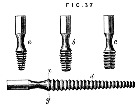
Fig. 37.
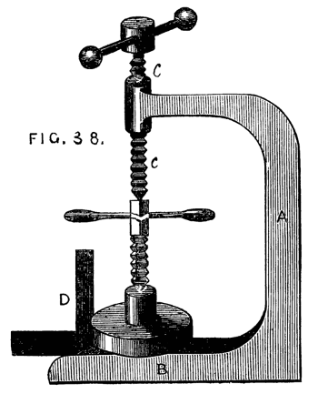
Fig. 38.
The upright drill should always have a place in the workshop. It is much easier to drill with it than in the lathe, and the mandrel will thus be saved considerably. The latter should never be used except for light work. A variety of drilling apparatus will hereafter be described in this series, so that we need not now write more upon this part of our subject.
Somewhat akin to the chuck described as the cup chuck with six screws, is a chuck mentioned in an old French work,[1] the purpose of which is to turn up a cylinder, with a point at the end, so as to insure the axial line being kept. In the ordinary course, the cylinder would be turned up with the point and carrier, or driver, chuck already described; the conical point would be then turned down as far as possible, and the mark of the back centre afterwards turned off by means of the boring collar. It is by help of a miniature lathe and boring collar in one piece that the pivots of the balance of a watch are finished. In both cases the work may be well done by the same process. The chuck now to be described requires no boring collar, but at the same time it does not seem to be well suited for any but light work; in which latter case however it would be advantageous, and must therefore have a place in our present paper. The body of the chuck is shown in section, in Fig. 39. A is the socket with screw to fit on the mandrel of the lathe. It will be seen that the chuck itself is hollowed out cylindrically, and in this cylindrical cavity slides a plug, c, bored conically, which can be fixed by a thumb-screw, h, traversing a slot in the body of the chuck. This cone is destined to receive one end of the cylinder to be pointed, which will, according to its diameter, centre itself in some part of the conical hole in the plug. The latter is made movable, so as to be adapted to the length of the article to be turned. At the outer end of the chuck is a groove dovetailed to receive a slide, shown clearly in the cross section B. The slide must be of sufficient substance to allow a clamping screw, f, to be tapped into it at one end, which screw must be long enough to reach when fully advanced nearly to the apex of the triangular opening seen in the slide. The action of the whole contrivance is as follows:—The cylinder to be pointed is placed in the conical cavity of the plug—the latter slid to or fro till the point to be turned projects a short distance beyond the mouth of the chuck through the triangular opening in the front slide; when it is fixed by a turn of the screw, f, which forms the third point of resistance, the sides of the triangular opening forming the other two. As the point or apex of the triangle is always in the diameter of the cylindrical chuck, it will only be necessary to move the slide itself in order to bring the axis of the cylinder to be turned in a line with that of the mandrel. As soon as this is accomplished so that the piece runs truly, the screw, g, is turned, and the slide fixed in position. A good deal of ingenuity is displayed by the inventor of this chuck, a description of which was published twenty years ago, and there are very many cases in which it will be called into requisition by the mechanic. With a little care, moreover, the amateur might make one for himself—the body of brass or gun metal, the plug and sliding part of iron or steel.
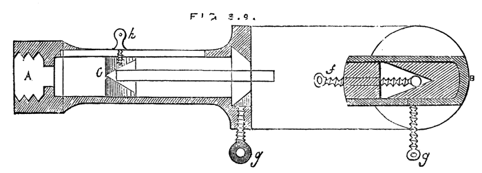
Fig. 39.
Amongst the various devices connected with the lathe, many of which, even as makeshifts, are valuable to the turner, is one not generally known for keeping up the tension of the lathe cord in whatever groove of the fly wheel or pulley it may be placed. The plan is not more ingenious than practical, and the writer is acquainted with one workman, a gasfitter by trade, who has had it in constant use for many years. Directly over the mandrel pulley is another of larger diameter, in which are two grooves of equal depth, fig. 40. This upper pulley is suspended on a movable arm, D, which is pivoted at E, and kept up by an india-rubber spring, F, or, as in the original plan (before these rubber cumulators were known), by a cord passing over a pulley, and having a heavy weight attached, as shown by the dotted lines. In the fig. A represents the fly wheel, B the mandrel, C the upper pulley. The lathe cord is very long, and passes upwards from A, over the upper pulley in groove 1, down again and round the mandrel, a second time over groove 2 of the upper pulley and down to the fly wheel. The tension of the cord is thus always the same, and is regulated by the spring or weight. If the cord is slipped to a smaller part of the lathe pulley, the slack is instantaneously taken up by the descent of the weight, and rising of the arm D, which in like manner yields to allow the cord to be slipped to the larger groove of the mandrel pulley.
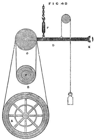
Fig. 40.
There are many other useful contrivances for chucking work in the lathe, a few of which will be noticed on a future page. The main thing to be attended to is the holding securely as well as centrally the object to be turned. If this is attained, the precise form of chuck is of little importance, and it matters not whether it be made of metal or wood. The latter has indeed, in some respects, an advantage resulting from its elasticity and the ease with which its form is modified.
Hand Turning of Wood.
We have now described the simple foot-lathe and chucks adapted for hand turning, but of the latter a great number may be provided, and will, in fact, accumulate as the turner proceeds to work upon objects of varied form and size. No chuck once made should be thrown away until it has become so reduced, from repeated alterations, as to be no longer serviceable. And now, before we commence actual turning, it will be well to offer a few concluding remarks upon the selection of a lathe. It will be evident from our previous remarks and illustrations that there is room for great diversity in the size and quality of this machine, and it is astonishing what excellent work is often turned out by an experienced hand from a lathe of the worst description. The simple pole-lathe, which is so out of date that we did not deem it worthy of notice in this series, with its reciprocating motion, like the little tool of the watchmaker, has, before now, supplied the cabinet maker with first-class work, and not many years since we ourselves stood before just such a clumsy tool, taking first lessons in the art. Our next step was to a lathe with wooden poppets, and flywheel of the same material, a mandrel made by a country blacksmith, which scarcely did even him credit; the value of the whole, with stand and beechen bed complete, was £2 sterling, and sufficiently dear at that price. Now, we do not recommend such a tool, and in the present day a much better may be had at that price, but, notwithstanding its evident defects, very tolerable work may be produced from it. We state this to deter the reader from a very common fault—namely, the purchase of an expensive tool and elaborate fittings when the purse is shallow, and the skill shallower still. In fact, any amount may be spent in lathes, and in fitting up a workshop, but to gain real pleasure and satisfaction from the pursuit of the mechanical arts, the outlay should not be more than the probable result in work fairly warrants. A hundred pounds is often expended in the purchase of a lathe, and a hundred shillings would more than purchase the work done by it. We speak from our own experience in this matter, and believe our advice proportionately valuable; and we well know the satisfaction that ensues when good work has been produced in spite of the defects in the appliances at command. If the means do not admit of the purchase of a good lathe necessity must decide the question, and an inferior one must take its place in the workshop. Nevertheless, we would rather counsel a certain amount of delay, and economy and hoarding, that a good foundation may be laid and a lathe purchased of such average excellence that future additions may convert it into a really serviceable tool.
It would be invidious and perhaps rather unfair in this little work to send the reader to any particular lathe-maker. There are several good and two or three first-class ones in London, and if prices range high, the work is at any rate of undeniable excellence.
There are also many cheaper firms than those alluded to, where the work is rather of rough-and-ready style; all depends on what class of work the would-be purchaser proposes to engage in, whether he intends to confine himself to plain hand-turning in wood, to the construction of steam engine, and other models of machinery in metal, or to the more beautiful finished work in hard wood and ivory, which develop the full power of the machine itself, and the skill of the accomplished turner. In the former cases, a very plain and inexpensive lathe will suffice. In the latter, it is absolutely necessary to purchase one of the best construction, at a tolerably high figure.
The best advice to those of slender means, and who, therefore, vastly predominate, is to sacrifice all else to the mandrel and collar. The latter may be bought at from twenty to thirty shillings, ready for mounting in detached wooden headstocks, and will be far superior to any that an ordinary smith can produce. In this case, the two poppets that carry the mandrel and centre screw should be connected together by a block of wood between them, which latter may be rounded off and shaped to something near the form of a cast-iron headstock.
The only care necessary in mounting such a mandrel, will be to keep the axial line parallel to the lathe-bed, and directly over the centre of the latter. Whether the mandrel is thus a separate purchase, as may happen from necessity, or obtained as part of the lathe, and fitted in a cast-iron headstock, it should certainly be hardened, and also the collar, if of steel. Both will take a higher polish for this process, and will run easier in consequence. The cost of such a mandrel is rather greater, because many warp or split in the process, and have to be thrown aside; and the labour of grinding mandrel and collar to an exact fit, is considerably increased. The gain, however, is greater than the loss to the purchaser, and the extra outlay must not, therefore, be grudged. It is very annoying to find a conical mandrel worn down by the collar after a twelvemonths' work; for a collar is thus formed on the conical part, so that it cannot be tightened up by the back screw.
The first tool to be noticed is the gouge, the form of which is a longitudinal section of a tube, and is shown in Fig. 41. Of this tool not less than three sizes should be selected, of the respective diameters of one inch, half-inch, and a quarter or three-eighths. When purchased, they require grinding, the bevel being too short. It is essential that this tool and the turning chisel have a long bevel, so that the cutting edge should be a very acute angle. (Fig. 41, not like 42.) It is impossible to do good work with the latter form of tool which is, nevertheless, of frequent occurrence in the workshops of amateurs. Both gouge and chisel must be sharpened on an oilstone (Arkansas or Turkey will be found the best) to a keen edge, and no pains must be spared in preserving the tools in this condition. Three sizes of chisel to match the gouges should be selected. The latter tool is not made like that intended for carpenter's use, with the edge at right angles to the sides, but is sloped like Fig. 43, so as to present an obtuse angle A, and an acute one B, and the cutting edge is central, the bevel being alike on both sides, so that the tool may be turned over, and used with either of the flat sides upwards. The handles of gouges and chisels should be much longer than those used by carpenters, and nicely rounded and shaped in the lathe. The most difficult thing to turn being a cylinder of soft wood; a description of the method of effecting this will be the best means of initiating the novice in the art of turning. In all the most perfect work by practised hands, there is a sharpness of edges and roundness of mouldings, that are exceedingly agreeable to the eye, and bespeak at once keenness in the tool with which the work has been done, and steadiness in the hand of the operator. The novice must aim at similar perfection, and to this end he must determine to avoid the use of sand-paper, and trust to his management of exceedingly keen tools to put a workmanlike finish to his work. To commence with the proposed cylinder. Let a piece of sound beech be selected for the first essay, as being less difficult to manage than deal, the grain of the latter tearing up in long shreds under the action of the tool. The first thing to be done, after sawing off the necessary quantity of sufficient diameter for the proposed work, is to round it off roughly by means of the hatchet and draw-knife, or spoke-shave. The next thing is to mount it in the lathe. For this purpose the prong chuck, or, better still, that represented as an improvement on the latter, and shown in Fig. 23B, must be screwed on the mandrel, and the work made secure by the aid of the back poppet centre. Care should be taken that the piece runs truly between the points of support, and that it revolves steadily without shake. There is no real necessity for using the compasses, or other contrivance for finding the exact centre at each end, as sometimes recommended, neither, indeed, is it always possible thus to find the axial line. It is easy to fix it at first lightly in its place, and ascertain by a turn or two of the mandrel, how nearly it runs as it ought to do. If it seems tolerably true, a turn of the back centre fixes it securely, if not, it can be shifted in any direction at pleasure. The tyro ought, however, to be warned that he is likely to be deceived in the size of the rough piece, and that he may very probably think it of sufficient diameter for the proposed work when in reality it is too small. Practice, or the use of the callipers, which are bow-legged compasses for measuring the diameters of work, will soon settle the question. The piece being properly fixed in the lathe, the latter is to be set in motion by means of the treadle, the rest having been first fixed as near as possible without touching the piece, and the T clamped parallel to it. If the tyro wishes to become a proficient, no pains must be spared to acquire the knack of working the treadle without moving the body to-and-fro. He must learn, therefore, to stand firmly on one leg, and after the wheel has been put in motion, he must let it and the treadle have its own way. He will thus soon feel when the crank has passed the dead point at the highest point of revolution, and the proper moment to bear down with the foot. It is not necessary to describe the precise movement, as a few trials will teach the method much better than any written description. At first it is hard work, and constant change of leg from the right to the left, and back again, will have to be resorted to to diminish the fatigue. Practice will, however, remove all difficulties, and allow the whole undivided attention to be given to the management of the tool.
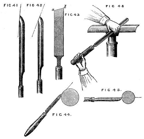
Fig. 41, 42, 43, 44, 45, 46.
The gouge must be held down firmly on the rest with the hollow side upwards, and the bevel of the edge forming a tangent to the work, Fig. 44. In this position it will cut freely and smoothly, and the edge will be preserved. If held horizontally, as in Fig. 45, it is evident that the fine edge of the tool will be immediately destroyed by the rapid blows it will receive as the rough wood revolves in contact with it. Its tendency in the latter position will be to scrape, instead of cutting, and the fibres of the wood will thus be torn out in threads, and the surface of the work be roughened. The gouge, then, being placed in the former tangential position, the right hand grasping the handle, the left the blade, as in Fig. 46, the tool is to be slowly slid along the rest, and a series of light shavings, more or less continuous, will be removed from end to end of the piece. Let the workman bear in mind that the tool is to take a firm bearing on the rest, and that it must not move to-and-fro with the inequalities of the piece to be turned. It is not necessary to remove large chips unless the turner has acquired from practice perfect command over the tools, and for the adept this chapter is not written. After the most prominent inequalities have been removed, the side of the gouge will come into use instead of the extreme end, and with this the work may be rapidly reduced to its intended size, always allowing, however, for the final cut with the chisel. Before the latter is taken up, the piece of work is to be rendered as level and true as can be done by the aid of the gouge alone; indeed, if the latter is of tolerable size, and skilfully used, a finish can be put upon the work by it almost equal to that which the chisel can produce and if the work in hand were a moulded pattern, with hollows and raised work, great part would have to depend on the gouge alone. In the present case the chisel must be used, and the method is as follows: Take a hold with both hands, as directed for the management of the gouge, but instead of the flat part lying evenly on the rest, the tool must be partly raised from it, so that only the lower edge takes a firm bearing. By this means the upper angle of the cutting edge (generally the most acute) is kept clear of the wood, and the latter is cut away only by means of the middle and lower part of the edge, as shown in Fig. 47. If placed as in Fig. 48, the acute angle, a, is sure to catch and stick into the work, spoiling in two seconds all that has been done. The chisel can be used with either of its flat sides upwards, and moved along the rest from right to left, or from left to right, or turned upside down, as Fig. 49, so that the acute angle is downwards. These positions are shown in the Fig. 47 to 51. The only care necessary is to keep the upper point clear, allow the chisel to rest as flatly on the wood as the above precaution will permit, and to take as fine and continuous shavings as possible. The chisel will be found to draw itself along in some degree as the cut proceeds, and when this action is felt, it is doing its work properly—still, it is a difficult thing to use a chisel well, and the tyro will fail many times and oft before he will succeed.
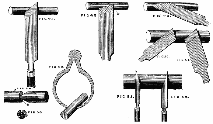
Figs. 47, 48, 49, 50, 51, 52, 53, 54, 55, 56.
The chances are that this initiatory lesson will result in anything but a correct cylinder—the surface will not be true like a ruler, but if tried by a straight edge it will be seen to be wavy. Tested by the callipers, Fig. 52, one part will be larger than another, even if the extreme portions be tolerably true to the proposed gauge. Now, the best turner on earth found just these difficulties, and nothing but perseverance and resolute determination will overcome them. Never mind spoiling the first piece of work, give up making it of a determined size, but do not give up making it a true cylinder. Keep the callipers at work, and gently level the prominent parts (you must work down to the size of the deepest hollow, for you cannot fill up such valleys like a railway engineer; you must throw down the adjacent hills instead), proceed gently, little by little; make the tool obey you, show it (as Ruskin speaks of pencil and brush) that you will not yield to its caprices and "henceforward it will be your most obedient servant." Having done the best you can with the surface of your cylinder, proceed to square up the ends, and mind the angle at this part is a right angle, square and sharp, not rounded off. Now this again requires care and a knowledge of the proper method. You will work chiefly with the lower corner of the chisel, and we shall best describe the management of the tool by supposing the cylinder an inch too long, and that the extra piece is to be removed. Now there are three positions in which the chisel can be placed to bring its lower corner in contact with the cylinder. First, with the blade perpendicular to the work; secondly, with the blade inclined to the left, Fig. 53, as if to round off the end of the piece; thirdly, inclined to the right, Fig. 54. Held perpendicularly it will cut a fine line, but penetrate slightly; alternately in the other positions it will remove a V-shaped piece, and thus the cutting off is to be begun. One side of the cutting, however, has to be perpendicular, the other may be as sloping as convenient. Now, it is to be remembered in cutting the upright side, which is the end of the roller, the chisel is to incline rather to the right, for this reason,—if it incline to the left a momentary inattention will cause it to take the path a, b, Fig. 55, the tendency being to cut a spiral track towards the left. The experiment may be made by gently resting the edge thus inclined on any part of the roller, when it will describe a spiral at once. To the right, then, the chisel must slightly incline, and it will cut off a thin curling shaving like Fig. 56, leaving the end of the piece quite smooth and shining. When the piece is nearly cut off, great care and lightness of hand must be used, as the central portion will have become weak and ready to break off before the work is finished. When it will no longer bear the chisel, take it out of the lathe, break it off, and neatly finish with the sharp chisel the central portion, and your first lesson is learnt. There is certainly very little of interest in turning an imperfect cylinder, for it is useless when done, but the alphabet of the art, though not amusing, must be first thoroughly mastered, and the rest will follow in due course. If, however, the work seem unreasonably dull and stupid, the cylinder may be converted into a tool handle, which will be at any rate a useful article, besides affording practice. No special directions are needed in addition to the above, except in respect to the ferrule. This is to be cut off a piece of brass tubing or an old gun barrel, or it may be had at the tool shops ready cut to any size. Begin by turning down the place for this ferrule, taking care not to cut it too small or the ferrule will drop off. Take the piece out of the lathe, and with a mallet hammer on the ferrule. Return it again, taking care to centre it in the old marks, and finish the handle. The brass or iron may be polished with a file for this first attempt.
Hollowed Work.
It is now necessary to speak of hollowing out wood for the purpose of making boxes, cup chucks, &c., and the latter, which may be made in any quantity, and of all sizes, will afford excellent practice in this part of the turner's art. The majority of work of this kind is done rather by scraping or fretting out than by cutting; side tools of the forms of Figs. 51 and 56 being used for the purpose. These however, are specially adapted for ivory and hard woods, the grain of which, being very compact and close, is not torn out in shreds by the action of such tools, as would be the case with softer woods. Where the latter material is used in quantity, as in the manufacture of wooden bowls, hook tools, like Fig. 57, are made use of, which cut on their upper edges. These are exceedingly difficult to use, though the practised hands of those brought up to the art, make them cut with a surprising ease and rapidity—fairly surrounding the lathe with a ceaseless cloud of fine shavings removed in the progress of the work. The difficulty experienced in the use of these tools is not confined to the novice, for the majority of turners accustomed to hard wood often cut a sorry figure in the manipulation of softer material with the aid of the tools in question. The hard and soft wood turners form, in point of fact, two distinct branches of the trade. We have in part anticipated this section, by speaking of the making a wooden chuck when describing the use of the metal chuck with taper screw. We shall, therefore, proceed to describe the best method of turning a plain wooden box with cover, but not screwed; the latter being reserved for more extended notice hereafter. The best material to work upon is sound Turkey boxwood, and care must be taken that it is quite dry and well seasoned, or, after it is worked up with, it may be, great care and trouble, the box will split, or the cover become so loose as to fall off, either fatality being sufficiently vexatious. We may mention, in passing, that hard woods of all descriptions may be had in large or small quantities of Messrs. Fauntleroy[2] and Co., 110, Bunhill-row, Finsbury, or of Jacques and Sons, Covent-garden. Most of the lathe-makers also supply it, especially Holtzapffel and Co., of Charing-cross, but the first-named is a large dealer, wholesale and retail, and his charges are moderate.
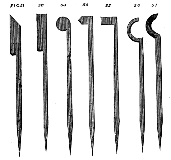
Figs. 51, 52, 53, 54, 55, 56, 57.
Supposing a selection made of size proportionate to that of the intended box, including cover and a tolerable margin for waste and accidents, proceed as before to rough it down between two centres and thus to reduce it to a cylindrical form—there is, however, no occasion to use the chisel at present, as we only need a rough cylinder. Remove this from the lathe, and if you have no brass cup chuck into which you can fit it, proceed to make one out of a piece of beech, ash or, if you have plenty, boxwood. Do not hurry the work, but cut the chuck out neatly, screw and fit it, as previously directed, on the nose of the mandrel. We shall suppose it as yet merely a short neat cylindrical block, quite solid. Place the rest with the tee across the end of the piece of wood, the top edge a little below the centre (by the thickness of the blade of the tool). For the latter select one of the three following—either will answer well—58, 59, 60. With one or the other drill a hole in the centre, keeping the tool quite horizontal across the rest. Enlarge this hole by a left side tool, working from the centre of the piece towards the outside, not taking the whole depth at once, but a quarter or half an inch at a time. You must hollow it out about one inch, and see how nicely you can fit the hollow to the size of the piece you are going to turn. You will, of course, have squared up one or both ends of the latter, which must now be driven tightly into the hollow chuck. If you squared the ends of the cylinder correctly and left also the bottom of your chuck level and true, you will be gratified by seeing the piece run evenly at once.
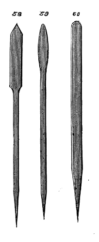
Figs. 58, 59, 60.
Fig. 61 shows a section of the chuck with the piece to be turned fitted inside it. Now take the gouge and chisel and reduce the piece to a plain cylinder, and take special care to square up the outer end. This may be done by the aid of a carpenter's chisel held across the rest, like the side-tool. If the end is much out of truth you had better use first the round-ended tool, Fig. 60, but if you have worked carefully from the commencement this will be unnecessary.
To ascertain the correctness of this part, apply a small steel square like Fig. 62, the blade of which slides through the brass part and is clamped by a small screw at the side. We show the method of applying this tool to gauge depth, test right angles, &c., in Figs. 63 and 64 . It is a most convenient and necessary instrument, and should be at once provided. Having thus ascertained that the end of your cylinder is at right angles with the side, take the point tool, Fig. 58, or the acute corner of your chisel, and, setting the lathe in motion, mark off the intended depth of the cover, as D, C, Fig. 61. (Observe, it is the cover and not the box that first demands attention.) Now proceed to hollow out the cover as you hollowed out the chuck, but with greater care. You must allow in the thickness of the top rather more material than you will eventually require, the thickness of the sides, also, may be a trifle in excess, but take the utmost care to make the inside rectangular, that is, the line f, g, perpendicular to g, D. Upon the correctness of this the fit of the cover will depend. This being done and tested as to truth with the square, as before, you may cut off the cover with a parting tool, Fig. 65. This tool is thin, with a cutting edge at the end, and is held edgewise upon the rest. The blade is made rather thicker near the end, so that as the tool penetrates the work it may not bind, but allow the small chips made by it to escape freely. The rest must be removed from its former position and placed parallel to the side of the piece, and the tee at such a height that the latter may, when the tool is held horizontally, point to the axis of the work. The tool should be occasionally withdrawn, and the point, instead of being kept precisely in one position, may be slightly raised and lowered from time to time, describing a small arc. It will soon be ascertained in what position it cuts most easily. There are different sizes of parting tool, some very thin in the blade, for ivory and precious woods, some thicker, for box and less valuable stuff, some with a notched end, forming two points, for soft woods, the action of all being similar to a saw tooth, or, in the last, to two adjacent saw teeth set out to clear themselves in working. Care must be taken that the thin blades do not bend and twist while cutting, especially after the cut has become deep. To avoid this do not hurry the work, but take a little at a time, and be careful to keep the tool with its sides perpendicular to the rest. With these precautions the cover will soon be cut off neatly. If care is not taken to allow for the necessary thickness of the cover, the turner will be mortified by finding that instead of the latter, he has merely cut off a ring, and he will have to expiate his want of judgment by beginning a new cover and making a shallower box. We name this to put him on his guard. Supposing the above work satisfactorily accomplished—the top of the cover, however, being (as will probably be the case) either convex or concave, requiring a little touching up and finishing, it will be necessary to turn down on the solid bit of wood left in the chuck the part A, B (Fig. 66), on which the cover will eventually rest. On no account, however, must this be now turned small enough, it must be left so large as not quite to enter the cover, because if it is now nicely fitted, and the box subsequently hollowed out, the cover is sure to be too slack, the wood shrinking in the process of hollowing out. This shrinking may be accounted for by supposing the rings of woody fibre, the result of yearly growth, naturally elastic, with a tendency to contract, each one, like a series of india-rubber bands, embracing that within it. The central ones being removed by the tool, permit the outer ones to contract, their particles approaching nearer to each other and the structure becoming more dense. This tendency causes those radial cracks so often seen in the ends of pieces of wood sawn from the trunk or limbs of the tree. The outer parts becoming drier than the inner, and prevented by the latter from shrinking, necessarily split, hence, when it can be done, the centre of such pieces is bored out, while the wood is yet full of sap, and the rest is thereby preserved. Where this cannot be done the ends may be covered with glue or resin; or paper may be glued on, to prevent access of air, and thus the drying of the outer portion may be so retarded as only to keep pace with that nearer the centre. The concentric rings thus shrink equally, and no radial splitting takes place.