APPENDIX.
Reading edition
Professor Willis's Tool Holder for the Slide Rest.
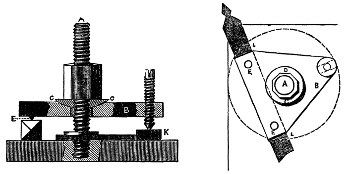
This—described and drawn first in "Holtzapffel's Mechanical Manipulation," to which work the author, and, indeed, most authors of books of the nature of the present, are indebted for much of their information—is now become very general, and from its perfect action ought to be universally used in all factories in which the lathe bears a part. It permits the tool to be set at any required angle upon the bed of the slide rest, and holds it securely when placed in position. It is likewise so constructed as to be easily removed from the table of the rest, so that other forms of apparatus may be attached if desired. One nut only has to be turned to fix the tool, this nut turning on a strong central screw, A, in the figure, the lower part of which, as far as the shoulder, is screwed into the top plate of the rest. This shoulder is directed to be made with flattened sides, so as to be capable of being unscrewed by the application of a wrench. The actual clamp is a triangular piece of cast or wrought iron, B, in the centre of which is a hole to allow this piece to go easily over the screw. The hole is hollowed out into a cup-shaped cavity, into which fits a hemispherical washer, shown at C in the section. The clamping nut, D, acts upon this washer, which permits the triangle to take up a position not necessarily quite parallel to the bed of the slide rest, and thus a tool whose upper and lower surfaces may not be strictly parallel will be securely grasped. The piece called triangular is not precisely of that form, but of the shape shown in the second figure, in which E, E, represent two hard steel pins, slightly projecting—one of these, E, appearing in the first figure. These pins rest upon the upper surface of the tool. At the third angle the clamping piece is drilled and tapped to receive a screw, which must work stiffly in this hole. Thus when a tool is placed in position, as shown, the clamping nut maintains a pressure upon the three points beneath the apices of the triangle. As thus arranged the tool would be stiffly and securely held; but Professor Willis has added a second triangular piece, nearly similar to the first, except that it is provided with a boss, in which a notch or groove is cut, K, in both figures, into which the point of the small screw falls. This lower triangle, which is free to revolve round the central screw, is also cut away at the line L, L, of the second figure, so as to form a guide or rest for the side of the tool, which is thus kept at the same distance from the central screw, and placed in a moment exactly under the studs or points of the upper plate. A careful inspection of the two drawings will make the precise arrangement clear. In making it, which is not very difficult, care must be taken to make the triangle of such size and so to place it, that no angle can overhang the top plate of the rest, in whatever position it may be. The hole in the upper triangle or clamp must be tolerably large and slightly conical—the base of the cone upwards, to allow this piece to take up a bearing, as described. The hemispherical washer is always in a horizontal position, and the hole through it may be only of sufficient diameter to allow it to pass freely over the central screw.
Munro's Planing Machine to be attached to the Lathe, and worked with the foot.
In the English Mechanic of Nov. 2, 1866, a brief notice was given of the above. The author of the present work having carefully inspected the machine and seen it in operation, considers it of such great value to the amateur mechanic, as well as to the professional turner of metal work, that he has had an engraving of the machine carefully made from a photograph, and has here appended it to illustrate the description given.
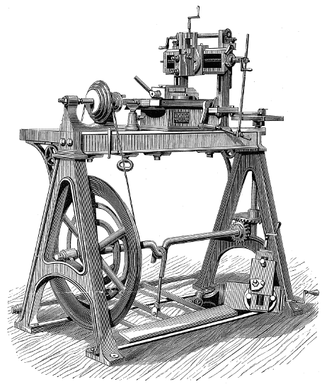
MUNRO'S MACHINE TURNING LATHE FOR PLANING, ETC.
It is a lathe for planing, cutting key-grooves in wheels, collars, &c., and cutting racks on the teeth of wheels. The lathe is of the usual construction, but outside the right hand standard is fixed a vertical spindle, which is made to rotate by a pair of bevel wheels, the pinion being fast to the end of the crank shaft, and in contact with a wheel of double the number of teeth on the vertical spindle. On the top of the latter is a crank-plate, which will give a stroke of ten inches or less at pleasure. The planing-machine is fixed by two bolts to the lathe-bed, and a connecting rod is attached to the sliding plate or bed of the planing machine, the other end of which is made fast to the pin of the crank-plate. The work is clamped by simple means to this sliding bed, and thus passes to and fro under the tool which, by self-acting gear, is made to traverse sideways after each stroke as in the large planing machines. The whole works almost noiselessly and with the greatest ease, each part being accurately fitted, and the whole well finished. For such purposes as planing the face of the slide valve and its bed in small engines, or shaping the guide bars of eccentric and other chucks, facing the frames of slide-rests, &c., it is exactly what is needed by the amateur, rendering the workshop complete for all purposes without the necessity for adding a large and separate planing machine, which takes up room that cannot always be conveniently spared. With such a lathe as that in the frontispiece, fitted with one of these planing machines, there is scarcely a model of machinery that could not be made. Any of our readers interested in mechanics would be wise to trip over to Lambeth and view the machine in operation; and the writer will guarantee, not only the most civil and obliging attention from the inventor, but the greatest pleasure and satisfaction from the working of the machine itself. There is a simple arrangement for key-grooving and slotting, by attaching the upper slide of the ordinary rest to the crank plate of this machine, in which case most of the apparatus is removed.
Hicks' Expanding Mandrel.
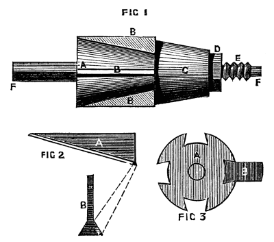
Figs. 1, 2, 3.
Mention of this has been made in the body of the work. It is used for turning rings and washers, and various sizes of these can be turned upon the same mandrel, so that a set of three will suffice for all the work likely to be met with even in the largest factories. Fig. 1 represents the mandrel complete. F, F is the central part, with a conical boss, A, cast upon it, and the whole turned with great accuracy. Four longitudinal dovetailed slots, seen plainly in Fig. 3, are then planed in the conical part, and into these are fitted steel wedges, Fig. 2, A and B, and B, Fig. 3. C, Fig. 1, is a hollow conical washer, which can be advanced over the central part when driven forward by the nut D. This washer, acting on the ends of the sliding wedges, causes them to move towards the large end of the cone A, and, from the form of these and of the cone, any washer or ring will be held tightly when placed outside these wedges, and will also be mounted concentrically.
Turning Spheres by means of Templates.
It is but right to state that the above method has been objected to by a practical workman, whose business has led him to study the matter closely. He states that it is impossible in this way to effect the desired object. As the writer has not been able to test the working of the apparatus on his own lathe, he felt inclined, at first, to withdraw the whole chapter. The objections offered, however, were not, to his mind, entirely satisfactory; and the opinion of other equally scientific and practical men being favourable, the chapter has been retained. It is possible, nevertheless, that there may be a mathematical reason which the writer is not competent to work out, and the objector being a man of great mechanical knowledge and experience, his remarks are worthy of consideration. The practical (not insuperable) difficulty appears to be the production of a proper tool for this work.
Plant's Geometric Chuck.
This chuck is put in motion by an entirely new method; none of its parts being attached to the lathe head, the whole can be put in motion or released in an instant, and without stopping the lathe.
The whole of its work is executed by the continuous motion of the lathe, so that, when the chuck is adjusted, any figure (no matter how complex) may be begun and completed without once stopping the lathe.
By the different arrangements and adjustments of the chuck and slide rest, an infinite variety of the most beautiful geometrical figures may be produced; and some of them of so strange and fortuitous a nature as to bid defiance to any imitation.
Description of the Drawings.
Fig. 1 is a front view, and
Fig. 2 a view of the back of the chuck.
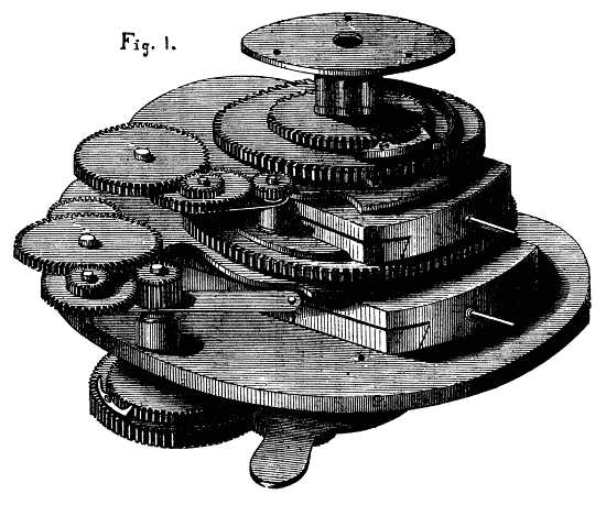
Fig. 1.
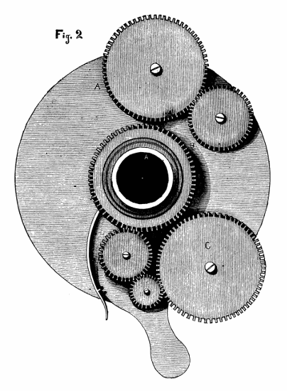
Fig. 2.
FRONT ELEVATION
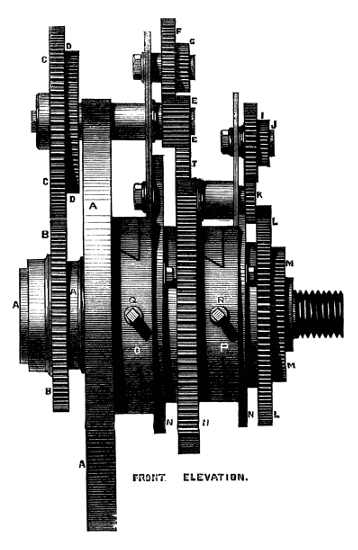
A A. The foundation plate screwing on the plate of the mandrel and carrying the whole of the other parts of the chuck.
B, C. The two driving wheels giving an independent motion to the chuck.
D. Angular wheel moving freely on the wheel C for the angular adjustment of the figures.
E. Pinion of any number of teeth fitting on the shaft carrying D and C.
H. Large wheel of 120 teeth, forming the foundation of the second part, and driven from the pinion E by the wheels F, G, and T.
L. Large wheel of 96 teeth driven by the pinions and wheels U, I, J, K, and forming the foundation plate of the third part, M, which carries the nose of the chuck.
N, N. Self-adjusting radius plates for carrying the various change wheels.
O, P. The eccentric slides of the first and second parts.
Fig. 2 shows the arrangement of the driving wheels and pinions on the back of the chuck.
The working of the chuck is as follows:—
If the pinion E has 20 teeth, and is geared direct into the wheel H, by means of an intermediate wheel, it will give six loops inwards if the motions are similar, and outward loops if the motions are contrary.
If the wheel H is driven from the pinion G it will give 12, 24, or 48 loops.
Pinion of 24 teeth will give 5, 10, 20, or 40 loops.
Pinion of 30 teeth will give 4, 8, 16, or 32 loops.
Pinion of 40 teeth will give 3, 6, 18, or 36 loops.
Pinion of 60 teeth will give two loops inwards, if the motions are similar, but, if the motions are contrary, it will produce an ellipse of any proportion from a straight line to a circle.
Other combinations will give circulating or overlaying loops.
By the different arrangements of wheels and pinions on the plates N, N any number of loops can be produced up to 2,592 in the circle.
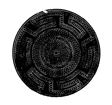
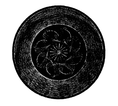
On the opposite page we illustrate some work executed with this chuck by Mr. Plant.
Fig. 3 is a side elevation of the chuck full size.
A, A, the foundation plate screwing on the nose of the mandrel, and carrying the whole of the other parts of the chuck.
B, C, the two driving wheels giving an independent motion to the chuck.
D, D, angular wheel moving freely on the wheel C, for the angular adjustment of the figures.
E, E, pinion of any number of teeth fitting on the shaft carrying C and D.
H, H, large wheel of 120 teeth, forming foundation of the second part, and driven from the pinion E by the wheels F, G, and T.
L, large wheel of 96 teeth driven by the wheels and pinions I, J, K, and forming the foundation of the third part, M, which carries the nose of the chuck.
N, N, self-adjusting radius plates for carrying the various change wheels, &c.
O, P, the eccentric slides of the first and second parts.
Q, R, the screws working the eccentric slides.
A Paper on the Principles which Govern the Formation and Application of Acute Edges, with special reference to Fixed Turning-tools, contributed by Mr. Dodsworth Haydon.
"The formation of the tools used for turning and planing the metals is a subject of very great importance to the practical engineer, and it is indeed only when the mathematical principles upon which such tools act are closely followed by the workman that they produce their best effects."—Holtzapffel, vol. 2, p. 983.
As the best lathe can do no more than place the work in the most favourable position for the operation of the tool, and the best tool can only do good work when applied as well as constructed on true principles, no argument is needed to prove the truth of the statement taken as the text of this paper.
But while many of our most eminent practical authorities, such as Nasmyth, Holtzapffel, Babbage, Prof. Willis, and others, have contributed valuable papers on the subject, no single writer can be said to have embodied all that should be known upon it as a whole.
Principle may be looked upon as the essence of practice, and in connection with this particular subject, the reduction of practice to principle is of comparatively modern growth. This will account for the fragmentary character and occasional difference of opinion, which marks the treatises of the above-named eminent authorities when compared with each other. As a step towards some more concise and perfect code of principle, I have endeavoured to collate and arrange in consecutive order, all those laws which govern the action of acute edged turning tools.
The object of this paper is not to supply patterns of tools, as the best form will be no better than the worst unless properly applied; but to set forth those general principles, which may enable the workman to distinguish between forms which are accidental and those which are essential, and thus to make the shape of any tool his servant rather than his guide.
Whatever the shape or purpose of any acute-edged tool may be, its action will always depend on the manner in which the extreme edge is applied to the surface acted upon; and as the same laws govern the action of every acute edge, whether formed on a razor or a tool for cast iron, it will assist a clear comprehension of this subject to consider first the action of edges generally, without reference to any particular tool.
The same edge may be made to act in four different ways, viz.: to cut, dig, chatter or scrape. Digging and chattering are intermediate stages between cutting and scraping, and are fatal to good work. Thus cutting and scraping remain the two standard principles, on one of which every tool should be made to act; and while cutting depends on the penetration of the edge, scraping results from using an edge so that it cannot penetrate. Consequently, the conditions most favourable to cutting will give the key to both principles of action.
Every cutting edge is simply a wedge, keen enough to guide its own path without depending on the grain or other accidental line of separation in the material on which it is employed; and when such a wedge is forced into any substance, it will show a constant tendency to penetrate in a line with that face which receives most opposition. The comparative amount of opposition which each face receives, will be determined either by one having more of its surface in contact with the material than the other as in Fig. 2, or by the material giving way on one side, as in Fig. 1 and 3. These last two figures illustrate the action of all paring tools, to which class cutting lathe tools belong. The dotted lines are added in Fig. 2, to show that the action of the edge is the same, whether it be formed by one or two bevels.
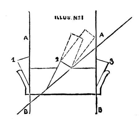
Illustration No. 1.(1, 2, 3)
Thus in all cases,—except when an edge is applied so that the pressure is equal on both faces,—one face will guide the course of the edge, and in paring tools this will always be the lower face, or that next the surface of the work.
The first consideration in placing any paring tool must therefore always be that, the lower face of the edge should lie as nearly as possible in a line with the direction the cut is intended to follow, so as to place the whole edge in its natural wedge-like position: for when any edge is compelled to act in a manner contrary to this, it will assuredly assert its natural tendency by digging and chattering in the direction of its lower face. But when the action of the tool is continuous as in turning, planing, or boring, care must be taken that this face of the edge does not actually rub against that of the work; and, to avoid this, Nasmyth recommends that the face of the edge should be inclined from the surface of the work at an angle of 3°. Babbage calls this angle "the angle of relief," because it relieves the friction; and to show how little variation is admissible in this angle, Holtzapffel places its maximum at 6°. In cylindrical work the angle of relief is estimated from a tangent to the circumference. Thus, in Figs. 4 and 7, the lines C, D, may represent plane surfaces or tangents at pleasure, and in either case the lower face of each edge is supposed to make an angle of 3° with these lines respectively.
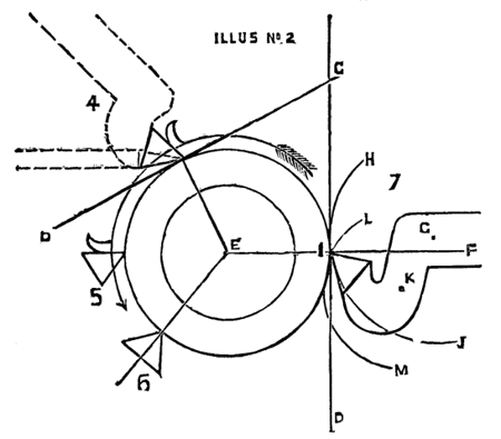
Illustration No. 2.(4, 5, 6, 7)
An examination of the nature of the force required to separate any shaving will show the importance of close attention to the above rule. Babbage has pointed out that this process involves two forces, which, though simultaneous in their action, are distinct in the nature of their operation. The first is that necessary to divide the material atom from atom, and depends on the kind of edge employed. The second force is that required to wedge back the shaving, so as to make way for the further progress of the edge, and depends on the manner in which it is applied to the work. Now in fibrous and cohesive materials, the amount of force required to wedge back the shaving is usually greater than that required to effect the initial penetration, and must always depend on the angle which the upper surface of the edge makes with the face of the work; while it is obvious that, whatever the acuteness of the particular edge employed may be, this angle will be reduced to the minimum obtainable with such an edge, by keeping its lower face as close as possible to the surface from which the shaving is being wedged off.[25] A comparison of Figs. 4 4 and 5 will illustrate this. Both edges are supposed to be of the same acuteness, viz., 60°, and in Fig. 4, where the angle of relief is only 3°, the edge of 60° will wedge off the shaving at the smallest available angle, viz., 63°, while the position of the same edge in Fig. 5 increases this angle to 90°.
Thus, as far as regards the force required to bend back the shaving, the edge of Fig. 5 might just as well be nearly square, or 87°, taking off 3° for the angle of relief. Indeed, this less acute edge would work better than one more acute but badly placed, as in Fig. 5; for the lower face here points too much into the work, creating the tendency to dig explained above. The same arguments and illustrations apply with equal force to drills and boring tools, and Fig. 5 may be looked at as representing one edge of a common drill, in which the acuteness is obtained by bevelling the under sides only, leaving the upper face of each edge perpendicular to the surface acted upon. Nasmyth has pointed out that the less acute drills of this class are made the better and more smoothly they will cut; for, so long as the upper faces are left square to the surface of the work, increasing the bevel of the lower faces can only increase the tendency to dig and chatter. Thus, whenever acuteness is desired in any cutting edge, it should always be obtained from the upper face; and the dotted lines in Fig. 4, suggesting a tool for metal in one case, and a common wood-turning chisel in the other, are added to illustrate this, by showing that the line of the lower face is common to both. No tools afford a better illustration of this principle in boring tools than the American twist drills, which owe the ease and beauty of their action to the spiral flutes being placed so as to give the necessary acuteness from the upper face of each edge, thus allowing the lower faces to be kept as close as possible to the surface of the work. There is yet one more important practical advantage to be gained from adopting the smallest possible angle of relief. The arrow in Figs. 4 and 5 shows the direction in which the strain of the cut will fall on the edges respectively. It has been shown that the position of Fig. 5 increases the amount of strain on the edge, and yet it is apparent that it is less able to bear this increased strain; for while this falls on Fig. 4 in its strongest direction—viz., almost down the length of one face—it falls on Fig. 5 across the end of the edge, thus rendering it far more liable to wear and fracture.
It is therefore evident that, in treating plane surfaces, the cutting action of any acute edge is most favoured when its lower face is placed nearly parallel with the surface acted on; and in treating cylindrical surfaces, when the same face occupies the same position with regard to some tangent of the circumference; or, in other words, when the lower face is almost at right angles to some radius of the circle, as in Fig. 4: and it follows that the tendency to penetrate will be most effectually counteracted when a line at right angles to the surface, or a radius of the circle, as in Fig. 6, bisects the edge, making each face equidistant from the surface which moves across it. Thus, Fig. 6 represents the scraping position; and it is obvious that all bow-drills or other tools, which are said to cut both ways, must really act on the scraping principle.
Practical illustrations in support of the universal application of these principles might be multiplied indefinitely; but two very common operations will suffice to prove that the position of the edge determines the nature of its action. If a penknife be not held with its blade perpendicular to the paper, when used for scratching out, it will be sure to hang and chatter; and the flatter a razor is held to the skin in shaving the more free will the chin be from uncomfortable digs and chatters afterwards.
The conditions which next demand notice in the case of turning-tools are those which must be observed to preserve the proper position of the edge under the strain put upon it. These relate to the form of the tool, and, in the case of cylindrical work with fixed tools, to the part of the surface at which the edge of the tool should be applied. Drills and boring tools require little notice in this respect, for, as the strain is round their axis, it is only necessary that their shafts should be strong enough not to twist or bend. It must, however, be remembered that when common drills are required to be very acute, the edges should be thrown up a little or hollowed out so as to give the acuteness on the upper face as explained above.[26]
Hand-turning is simply a matter of manual dexterity, and as any part of the same plane or the same circumference presents the same surface to the edge of the tool, the correct relation between the edge and the surface can be obtained in many places, and therefore the particular point at which the edge should be applied is simply a matter of personal convenience, and may vary with the height of the lathe or that of the workman, or the shape and nature of the tool employed. The use of the graver affords a good illustration of this; and it may be remarked, in connection with this tool, that none is more simple in construction, more perfect in principle, or more convenient in application. When its use is once thoroughly mastered it will do anything from smoothing a pin to roughing out a cylinder four or five inches in diameter. The graver is simply a square bar of steel ground off obliquely at the end; and by varying the obliquity of this slope the act of grinding one plane face will give two cutting edges of any desired acuteness, and three heels from which to use these edges at choice. In hand-turning only one edge of the graver is used at a time, and the lozenge-shaped face is made the lower face common to each edge. Now, when the graver is used for roughing, the point is generally buried in the clean metal below the central line of the work, and the lower face is placed against, and takes the shaving from, the little shoulder which it forms on the cylinder. When the graver is used for smoothing, the lower face is placed nearly flat against the face of the work, and the edge is generally made to bite on, or a little above, the central line. But for very light finishing cuts the graver may be used from the heel at the bottom of its lozenge face, and in this position its point is over the top of the work, bringing the biting part of the edge still more above the central line. Thus, the only three points to consider in placing the tool in hand-turning are—first, that the lower face of the edge should occupy the proper position with regard to the surface; secondly, that the handle of the tool should come up conveniently to the hands of the operator; and thirdly, that while these two conditions are observed, the heel of the tool should be able to take a firm bearing on the rest.
The best rule for hand-turning is, therefore, to apply the tool to the work, with these ends in view before fixing the rest, and then to bring that up to the necessary position.
When the heel of any hand tool has a firm bearing on the rest, and the edge is applied in the wedge-like position, the preservation of this during the progress of the work depends on delicacy of touch rather than muscular power. But when the edges are applied out of their natural line, it puzzles a strong wrist to keep them to their cut at all without digging into the work. This affords the best practical illustration of the necessity of careful attention to the position of slide-rest tools, which are deprived of all power of accommodation to the sense of touch, and which therefore require accurate adjustment in the first instance.
For the motion of the tool is now confined to that of the rest, and as this moves in horizontal planes, the edge of the tool must be applied to the work on that parallel plane which passes through the lathe centres. The reason for this rule will be at once apparent, if the edge be not placed on this central line in facing up a plate—for then it will lose its cut before reaching the centre, leaving a core untouched. Now although it would require an exaggerated error in the position of the edge to lose cut altogether in turning a cylinder, yet this example proves that, unless the edge be applied exactly on the central line the relative position between it and the surface of the work, on which the cutting action depends, will imperceptibly change with the reduction of the work; and supposing this to vary much in diameter, the same tool may cut beautifully on one part and badly on another. Fig. 4, which illustrates the cutting action of the edge, has been purposely placed on a part of the circle where a slide-rest tool could only act for a very short time, in order to draw attention to the difference between those conditions which govern the cutting action, and those which depend on the motion of the rest from which the tool is used. It is obvious that if Fig. 4 were moved inwards on a horizontal line the edge would pass over the smaller circle without touching it. The illustration is of course exaggerated, but it proves that Fig. 7 is the only position in which the tool will cut over varying diameters without some change in the relative positions of its lower face and that of the work. Hence the usual instructions to apply the edge about the centre of the work. But Babbage has observed, that however good this direction may be as far it goes, it is insufficient and liable to mislead when given alone. It is impossible to do away with elasticity when the tool is supported at some lateral distance from the line of strain, as in the slide rest or planing machine; and unless this elasticity is counteracted by the position of the tool, it may upset the best position of the edge. To meet this, Babbage gives the following rule—First, consider whereabouts the tool itself will bend under strain on its edge, when fixed in the rest; and then take care that this part of the tool, which Babbage calls "the centre of flexure,"—is placed above a line joining the centre of the work and the edge of the tool. Fig. 7 will explain the reasons for this rule and the consequences of neglecting it when there is much strain put on the edge.
Let E, I, F, be the line joining the centre of the work and the edge of the tool. Then if G above this line be the centre of flexure, when the tool bends its edge must follow some part of the arc, H, I, J, from G as a centre, and will be thrown out of the work. But if K below the line, E, I, F, be the centre of flexure, then, under the same circumstances, the edge will follow some part of the arc L, I, M, from K as a centre, and must dig into the work. It is important to recognise this principle, because while it shows that every tool in which the top of the edge stands above the shaft must be liable to the evils resulting from elasticity, it shows also that even cranked tools may fail to obviate the danger, unless care is taken to place the weakest point in the shaft above the central line. Babbage remarks, that although it is not always possible to strengthen any part of a tool, it is always possible and sometimes desirable to make some particular point weaker than the rest, by cutting away a little where the weak point should be. Fig. 9 shows that the crank principle may be applied in another form, and although the crank is upwards in this case, the same object is attained by making P the weakest point, and placing it above the central line, N, O. This form, however, is only used for light finishing cuts; for any unnecessary length of crank evidently adds elasticity, and Holtzapffel observes that, "in adopting the crank form tools the principle must not be carried to excess, as it must be remembered we can never expunge elasticity from our materials, whether viewed in relation to the machine, the tool, or the work." The crank, therefore, should only be just sufficient to give the edge the right direction if the tool should spring; and Holtzapffel remarks, that as a tool will generally bend somewhere in the central line of its shaft, it is sufficient if the top of the edge is kept on or just below this line, as in Fig. 8. Referring again to Fig. 7, and looking at the line C, D, as a plane surface, and I, F, as a line perpendicular to that surface, the same arguments and illustrations apply to the form of a tool in the planing machine. The point at which the tool is now applied ceases to be of moment.
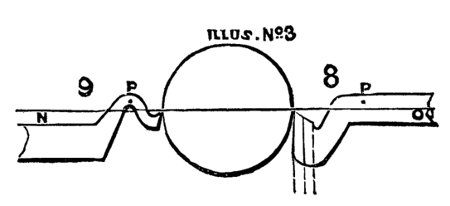
Illustration No. 3.(8, 9)
Having considered the conditions necessary to insure the best cutting action of acute edges and the preservation of that action during the progress of the work, it remains to treat of the edges most suitable to particular materials, the method of giving them any desired angle, and the manner of applying slide-rest tools so as to obtain the best work with the least expenditure of force and time.
Willis observes that different metals and qualities of the same metal require to be treated with edges differing in their degree of acuteness, and all the standard authorities concur in giving the following code as near enough for all practical purposes. The modification of these angles is ruled by the general principle that fibrous and cohesive materials require more acute edges than crystalline and granular substances, as will be apparent in the following code:—
Wrought iron and steel 60°
Cast do. do. 70°
Roughing brass 80°
Finishing do. 90°
Thus the edges available for the metals commonly treated in the lathe find their maximum at 90° and minimum at 60°. The maximum requires no explanation, as when any edge is larger it ceases to be an acute edge.
With regard to the minimum of 60°, Babbage has pointed out that this is dependent not only on the strength necessary to resist the strain of the cut, but further and chiefly on the temper which must be preserved in the edge; and if this be less than 60° the mass of metal composing the extreme edge will be too small to carry off the heat generated by the cut, consequently the extreme edge would soon lose temper and become useless.
But these different edges are formed in very different ways according to the purpose for which the tool is intended; and this will be best understood by comparing the action of a hand-turning chisel with that of a pointed slide-rest tool. In the first case the edge is applied at an oblique tangent to the surface, and removes the shaving by passing under its whole width, much after the manner in which an apple is pared, or a ribbon unwound from a stick, when the lower edge of one turn just overlaps the top edge of the turn below it, and so on. In this case the shaving can be cleanly detached by one straight edge. But the position and motion of the slide-rest tool being perpendicular to the axis of the work, its action becomes that of uncoiling rather than paring; and as a cord or wire wound round a stick touches the face of the stick in one direction, and the coil next to itself in another, so in this case the width and thickness of the shaving lie in opposite directions, as illustrated by the dark band in Fig. 10. Consequently, unless the shaving be cut simultaneously in these two directions—viz., from the face of the work on one side, and from the matter under removal on the other, it is obvious that it must be torn from the work in one direction, thus increasing the labour and spoiling the appearance of the work if the tearing should be from its face. Now, in practice, at any rate in the rough cut, it is usual to take the width of the shaving from the superfluous matter; and if the tool be placed, as in Fig. 11, it can only cut on one edge; thus the edge of the shaving will be torn from the face of the work, while the point of the tool will trace a fine thread in its progress along it, leaving the face with a rough unfinished appearance.
But if the edges be formed so that they can be placed as in Figs. 10 and 12, then both can cut simultaneously, and the screw-like trace of the point may be obliterated. This method of using the tool will leave the work with a good face from the first rough cut, leaving very little for the finishing cut to do; in addition to which the labour will be reduced to a minimum, thereby permitting a much heavier cut from the same amount of force. In turning any plane surface the corner of the edge should be sufficiently relieved from it to avoid the danger of catching; but, in turning cylindrical surfaces, if the tool be carefully made and placed, the slope of the upper surface will carry the corner out of cut. Experiment must decide the exact adjustment; but the great aim should be to keep the face of the tool next the work as nearly parallel with it as possible, because it is only that face which leaves any trace of the tool's action on the face of the work—the action of the other edge being lost with the shaving.
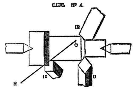
Illustration No. 4.(10, 11, 12)
Thus tools may be broadly divided into two classes—viz., single-edged and double-edged—remembering always that this distinction refers to the manner in which they should act, and not to the number of edges which it may be convenient to form on the same tool. In single-edged tools, whether there be one or many edges, each edge acts independently in removing its own shaving, and may therefore be formed separately. In this case a longitudinal section, showing the angle of the point, will give a true idea of that of the cutting edge. But, in the case of double-edged tools, as the two edges should co-operate in the removal of the same shaving, they must also be formed so that, while each lower face can occupy its proper position with regard to that surface of the work opposed to it, both edges shall possess the same degree of acuteness. In this case the two edges are formed by three planes—viz., two side faces and one upper surface common to both; and the angle of the point is now not only not that of the cutting edges, but has not even any fixed relation to them, for the cutting edges may vary some 25° or more on the very same longitudinal section of the point.
Prof. Willis has pointed out that in these tools the angles of the cutting edges depend on the section and plan angles of the point conjointly (Fig. 8 is a section view; Figs. 10, 11 and 12 are plan views). From this it follows that cutting edges of exactly the same angle may be obtained by a great variety of combinations in the plan and section angles; and in note A, U, of Holtzapffel's work, vol. ii. p. 994, Prof. Willis has given a table, showing some of the different combinations by which cutting edges of certain angles may be produced with accuracy and simplicity. The following short table is arranged from this source and though much abbreviated will be found sufficient for all ordinary purposes.
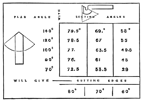
PLAN ANGLE WITH SECTION ANGLES
140° 79.5° 69° 58°
120° 78.5 67 55
100° 77 63.5 49.5
90° 76 61 45
70° 72.5 53.5 29
WILL GIVE ——— CUTTING EDGES
80° 70° 60°
The graver will again serve to illustrate the use of this table; for although only one edge is employed at the same time in hand turning, it belongs properly to the double edged class. This will be very apparent if a graver is held point upwards side by side with a point tool, and the dotted lines are added in Fig. 8, to make the similarity of form more evident. Now Holtzapffel has said of the graver when employed for its original purpose of engraving, that "no instrument works more perfectly," pointing out that, while both the edges are engaged in cutting the same shaving, both the lower faces of the edges are respectively inclined at the smallest possible angle from the sides of the V-shaped groove. Fig. 10 has already been used to illustrate the best position of the slide-rest tool, and if the illustration be turned round until the letters Q, R, read horizontally, and this line be taken to represent a flat surface with the graver acting upon it, it will be seen that the shaving is removed in exactly the same manner in both cases; the only difference being that the section of the shaving is triangular in one case and rectangular in the other. But so far as the tool is concerned the action is identical in each case, thus proving that every point tool may be so made and placed as to merit Holtzapffel's eulogium on the graver, and that this simple tool is in fact the type of all double-edged tools.
The graver being made from a square bar has of course a plan angle of 90°, and using it to illustrate the table, we will suppose that it is desired to give it two cutting edges of 60° each. Referring to 90° under the heading of "plan angle," 45° will be found on this line in the column over "cutting edge" 60°; denoting that the section angle of the point, i.e., the slope at which the graver is ground, must be 45° to give the desired edges. In the same way, if the section angle were 61° the cutting edges would be 70°. But taking the plan angle of 120°, the table shows that this would produce the same cutting edges of 60° with the larger section of 55°; and from this we have the important rule that, in obtaining cutting edges of any given degree of acuteness the larger the plan angle is made, the larger also may be the section angle. Thus pointed tools though constructed on the principle of the graver are an improvement on it in its simple form; for by making both plan and section angles as wide as possible, it is obvious that the strength and durability of the point will be much increased. It is, therefore, always better to give slide-rest tools a large plan angle, as in Fig. 12; and plan 120°, with section 55°, will be found a very useful and durable tool for surfacing purposes with wrought iron. When there are rectangular corners to cut in and out of, of course the plan angle cannot be more than 90°, and then it is well to sacrifice a little of the acuteness, as the section of 45° makes the point rather too weak. It is also worthy of remark as a mathematical fact, that unless the plan angle exceed 60°, it is impossible to obtain two cutting edges of that degree of acuteness; and in any case, such a plan angle would be radically bad, because it could not be used on the double-edged principle without undercutting the shaving. It is somewhat remarkable, in connection with this point, that while Holtzapffel, vol. ii. p. 536, recommends prismatic cutters, he should add a footnote which indirectly but most conclusively corroborates Prof. Willis' condemnation of that particular form, by admitting that the proper degree of acuteness cannot be given to both edges.
As the practical result of a circular edge is to cut in two opposite directions,—the edge passing gradually from one to the other,—so round-nosed tools belong properly to the double-edged class, and are open to great objections unless carefully formed on this principle.
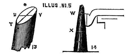
Illustration No. 5.(13, 14)
This is illustrated in Fig. 13, representing an oblique section of a round bar; and supposing the section to be made at an angle of 45°, it is obvious that the highest part of the edge at S will be exactly of this angle, while the lower point at T will be 135°, and the side points at U and V will be 90° each. Thus, between the point S and the points U and V on each side respectively, the edge will gradually pass through a range of 45°, consequently no two adjacent points on the same side will be of the same angle, and the highest point S may be too acute to stand while the lowest, U or V, is too blunt to cut.
Whenever, therefore, it is intended to round the nose of the tool, it should be first formed as a double-edged point tool, with a section angle agreeing as nearly as practicable with the intended degree of acuteness in the edge, so as to secure the highest points from being too weak, and the table given above will show what plan angle must be used, in combination with this section, to secure any part from being too blunt.
Thus, supposing a circular edge of about 60° is desired, the section of 58° approaches this most nearly, and if the plan of 140°, which, with this section, gives two straight cutting edges of 60°, be adopted, there can only be a variation of 2° in different parts of the edge. But it will be observed that this combination admits of very little rounding; and although less acute edges, being obtainable with a smaller plan-angle, admit of rather more rounding, it may be taken as a general rule that when any tool is much rounded on the nose, so as to present a large segment of a circle, different parts of the edge must vary considerably in acuteness. Although Professor Willis objects to rounding the nose of a tool at all on account of the necessary variation in the character of the edge and some other reasons, I am disposed to think that when the tool is carefully formed on the principles given above, it is very advantageous to round off the point slightly for taking heavy cuts; and I have found this form a favourite one in such workshops as Woolwich Arsenal and Portsmouth Dockyard. But care must be taken to place the nose of the tool towards the width of the shaving (presuming that this is taken from the matter to be removed, as it usually is,) for unless the edge is straight, and almost parallel with the face of the work as it leaves it, the face would be marked with a series of concave grooves of greater or less width, according to the feed given to the tool; and even when this is very slow, if the curved part of the edge were placed towards the face of the work it would present the appearance of corrugated iron, when examined under a magnifying lens. Willis further advances against the round nose that, as the shaving removed by it must be of a curvilinear section, it will oppose more force in rolling itself off the edge, than a flat shaving. This would be quite true if a flat shaving could be rolled up on itself like a piece of tape or ribbon; but I think the professor has overlooked the fact that when two cutting edges have one common upper face the shaving must be bent laterally as well as in its length; and I am disposed to think, from practical experiment, that there is very little difference on the point of the force required, and that when a point of large plan angle is just rounded off it stands better and cuts sweeter than when the point is not so rounded. But this only applies to heavy cuts, and for ordinary surfacing work nothing can act more perfectly than a point tool of wide plan-angle placed as described above. If a double-edged tool, with edges of 60°, be thus used in turning wrought iron or steel, and be well lubricated with clean water during the progress of the work, its face may be left with a burnished brilliancy that a touch of the finest emery would spoil. But, as the scheme of this paper is confined to the principles which determine the action of edges, and the rules by which those edges may be formed with certainty, it will be well to conclude these remarks with a few hints as to the construction of ordinary slide-rest tools. Bearing in mind that all double-edged tools belong to the graver class, it is well to form the side faces carefully in the first instance, and then never to alter these, but to keep the tool in order by grinding in the upper surface only, just as the graver is treated. Nasmyth's cone gauge, illustrated in Holtzapffel, vol. ii., p. 534, and also in "Baker's Mechanism," p. 236, affords a ready means of forming the side faces with accuracy. But the range and convenience of this gauge is much increased by dispensing with every part of the arrangement, except the cone itself. This can be made of any piece of stout metal bar turned truly, with the slide-rest set at an angle of 3°, and the base should be broad enough to stand steady by itself when squared off truly in the lathe, as in Fig. 14. Two marks can then be made upon it: one as at W, showing the exact height of the lathe-centre when the cone stands on the bed of the lathe, and another as at X, showing the height of the centre when the cone is placed on any given part of the slide-rest. Thus, in whatever direction the tool is to be used, its adjustment can be accurately made in the first instance on the slide-rest itself, and again tested after the tool is clamped down.
It is too common a practice in setting slide-rest tools to wedge up one end or the other, with regard only to the application of the edge on the central line. But this generally sacrifices the position of the lower faces, which is essential, to a consideration which has been shown to be only secondary. The best plan is to keep several strips, varying from 1/32 to ½ inch in thickness, but all about as long and wide as the shaft of the tool. These can be made of bar iron for the thicker strips, and sheet iron or tin for the thinner ones; and by using any two or three of these together, the tool can be packed up parallel to the bed of the slide-rest. The adjustment of the edge can thus be made with the greatest ease and certainty without altering the relative position of the lower faces.
It may be well to remark that in using the cone gauge, it is the lower faces of each edge which are to be tried against it, and not the front line of the point, as the inclination of this rule will vary slightly with variations in the plan-angle of the tool, although the slope of the faces remains the same. But the section angle is always to be estimated from the front line, whatever its slope may be.
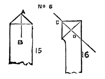
Illustration No. 6.(15, 16)
When the principles which this paper has endeavoured to embody are once thoroughly understood, no handy workmen need ever be at a loss to form and apply his edges with the best effect under any shape the circumstances may require. The first point to be observed is the manner in which the work should be attacked—that is to say, whether the removal of the shaving or scraping requires the use of a single or double-edged tool. The next point is the position of the lower face or faces of the edges, so that they may be applied in the required direction, and in the position explained above. This involves the nature of the treatment best suited to the material, both as regards the kind of edge employed and the principle on which it should be applied—viz., cutting or scraping. In double-edged tools the position of the two lower faces determines that of the point, which is simply an accident resulting from the meeting of the cutting edges; but which, when so determined, affords a guide for the slope of the upper face. This must be so ground that it gives each edge the same degree of acuteness. Thus, in Fig. 15, the point of the tool being at A, the slope must be made in the direction A, B; while, in Fig. 16, the point being at C, the slope of the upper face must be in the direction C, D.
The writer is fully aware that those who expect to find "a rule of thumb" in this paper, will be miserably disappointed. But while he is conscious that the principles of which he has treated admit of a much fuller and yet more concise definition, he would remind the novice that there is "no royal road to learning," and that where practice of hand is wanting it can only be supplied by greater knowledge of principle. His object will therefore be fulfilled if this supplementary paper can supply any explanation or illustration of principle that may add to the practical utility of a work so exhaustive of its subject as "the Lathe and its Uses."
Detached-cutter Holders.
Where amateurs experience inconvenience in making their tools from the want of a forge, the use of detached cutters in a tool holder will be found of the greatest advantage for outside work. Even in plain turning there must always be some special forms for cutting into odd corners and deep grooves; but with a good tool holder and a grindstone, which is an indispensable piece of furniture in every metal turner's shop, the cumbrous array of slide-rest tools may be reduced to a few special forms and a very small box of cutters. These also possess another great advantage; for the spirit of the old adage quoted by Holtzapffel—
"He that would a good edge win Must forge thick and grind thin,"
may be carried out far more conveniently than in the case of whole tools which are generally filed into shape before tempering, and when worn down must go to the fire again and have the process repeated. But the detached cutter admits of being tempered evenly throughout its whole length and ground up afterwards as long as it lasts, without going to the forge again to the deterioration of the steel.
The patterns of tool-holders are innumerable, but very few are good for general service, because most of them are arranged so that the natural sides of the cutter are used for the face or faces of the edge. Thus either the plan angle of the point is limited to the angles presented by the transverse section of the cutter employed, or else the section angle is fixed by the position in which the cutter is clamped. Holtzapffel's arrangement is open to the first objection, Babbage's to the second. To obviate this inconvenience, Prof. Willis arranged a holder which clamps the cutter at an angle of 55° from the horizontal line. Thus no side can be used either for the lower or upper face of the edge, but any faces can be ground upon it; and the plan and section angle of the edge may be varied at pleasure within the whole range available for metal turning. Prof. Willis's holder for the cutter is almost a facsimile of his admirable tool-holder for the slide-rest, than which none is more convenient or can act more perfectly. But the arrangement is a little complicated for a cutter holder, and must be very carefully made with the knowledge of certain laws, if it is to insure a perfect grip of the cutter. It is also designed for the use of sound wire cutters which require filing flat on one side.
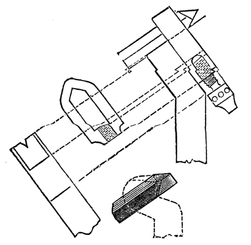
Adopting Willis's inclination for the cutter I have found that all its advantages may be secured with a simpler form of holder and common square for steel for the cutter. The holder is simply the modification of an old pattern to suit the inclination of 55°, and the sketch needs little explanation beyond saying that the nick in the solid part should be rather less than a square angle, and made perfectly true all the way down, or, if anything, rather hollowed in the middle, so as to insure the greatest amount of pressure at the top and bottom, as otherwise the cutter might not sit quite true and firm. The angle at the end of the strap against which the cutter bears should be rather more than square, both to allow for any want of exact truth in the squaring of the cutter and to avoid the wedging action which would be set up on tightening the screw if this angle were less than square, as this could of course create a risk of splitting the strap. The end of the screw and the cup in which it fits should be round, as this allows of a little play and insures a truer grip in the strap than a pointed screw working into a conical hole. A perspective sketch of a detached cutter is added, with dotted lines to show how exactly the arrangement of the faces can be accommodated to the positions which have been shown to be the best in solid tools for the slide-rest.
D. Haydon.
New form of Rose Engine by E. Taylor.
Seeing that the Editor of the above Articles has illustrated and described Holtzapffel and Co.'s Rose Cutter and two methods of executing rose cutting, the latter being the ordinary rose engine, I am induced to send you a description of a method that I have adopted whereby I can with considerable despatch execute this description of turning.
I will first preface my description by saying some thirty years ago I purchased Ibbetson's Book on eccentric turning, and I was so much taken with it and the illustrations, that I determined to make myself in accordance with his description and engravings an eccentric chuck; and although I was a long time about it, being at the time much otherwise engaged, I succeeded beyond my expectations, and was enabled to do some very fine work with it; and I have never regretted the time I spent over the chuck, as I became familiar with metal turning and screw cutting flying in the lathe, which latter I was surprised to find how easily I could execute. However, I was much disappointed in the usefulness of the chuck (Holtzapffel's eccentric cutter, which I purchased is far more useful), and also with the tediousness of using it (fancy stopping the lathe to alter the chuck 360 times or 180 times to cut a row of circles either distinct or overlaying each other), and there was also a certain vibration occasioned in using the chuck which I also disliked. I therefore determined to cut up some rosettes and convert my headstock into a rose engine, to effect which object I got Holtzapffel and Co. to return up with a new steel collar and make my mandrel traversing. I cut myself a rosette both ways with 16 waves, and I was much pleased with the variety of work I could perform with this one, but the rosette took me a long time to make, and disheartened me from cutting up a variety. It, however, occurred to me that if I added an extra mandrel by the side of and attached to my headstock, and on which extra mandrel, if I had an eccentric chuck connected with a rod to the wall of my room, I could get my headstock to oscillate, and by connecting and multiplying wheels cause as many waves on each revolution of my principal mandrel I pleased; this after much time and patience I succeeded in doing, and worked it with the hand motion often adopted for rose work. After between two and three years, I put the extra mandrel over my principal mandrel instead of by the side as before, to enable me to dispense with the hand motion and to work the upper mandrel with the slow motion on my lathe wheel, and which I found a very great improvement, and I now give the details of the plan I have adopted for the benefit of your numerous readers.
The drawings are to a two-inch scale, or one sixth of their full size.
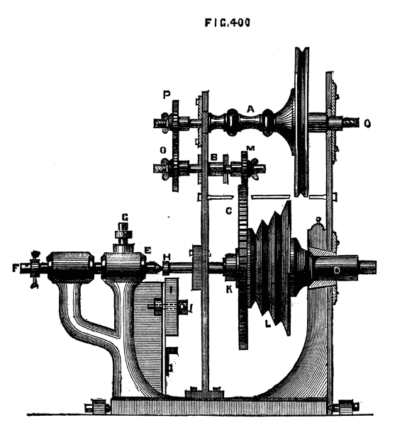
Fig. 400.
Fig. 400 is a side view of my headstock (part in section) with the upper mandrel, A, added, showing the connection by an intermediate spindle, B, with the large cog wheel, C, on my lower mandrel, D, and other additions.
The back centre, E, of my headstock is connected with the back screw, F, and drawn out or pushed in with it, and is fixed by the set screw, G. When drawn out the steel screw, H, at the end of the mandrel, D, removes to receive the screw guides which are then fastened by it, and the piece, I, with segments of a thread to match the guides, is slid up by a wedge to the guides and then fastened by the screw J, I, can also fix some roses cut on the side, and other apparatus with this screw H.[27]
The large cog wheel, C, is screwed up with the screw, K, to the mandrel pulley, L. On the front of the pulley is the division plate as usual.
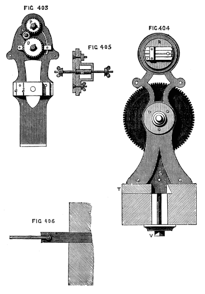
The intermediate adjustable spindle, B, is carried in a frame shown separately by Fig. 405; it is allowed to rise or fall as may be required for the wheel, M, to gear with the great wheel, C; provision being also made for an intermediate wheel, N, (see Fig. 403) to connect the wheel, O, with the wheel, P, on the upper mandrel when required.
The eccentric chuck is fixed on screw Q of the upper mandrel.
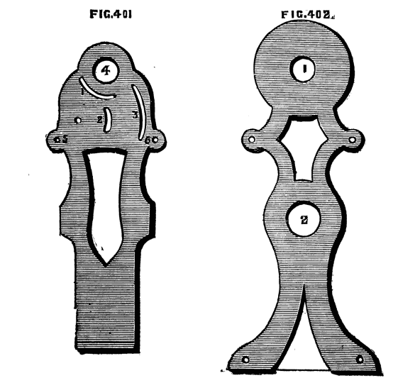
Fig. 401 is a plan of the mould for the back cast-iron upright, fixed to the headstock with screws at the foot, showing the circular grooves 1, 2 and 3, necessary for the spindles for the connecting wheels; the centre hole, 4, is for the gun-metal collar, or the upper mandrel.
Fig. 402, is a plan of the mould for the front cast-iron upright; the centre holes 1 and 2 are for the collars of the mandrels. No. 2 is made to just fit over the steel collar of the lower mandrel, and is fixed to the headstock by a brass rose and three screws; it is also fixed at the foot with two screws to the headstock.
Figs. 401, 402.
These two castings, 401 and 402, are bolted together with two bolts and nuts through the holes 5 and 6, as shown in Fig. 400. Fig. 403, is a back view of the additions, showing the cog wheels and their connections, also the brass bearings for the lower mandrel required when allowed to traverse. This was a solid piece of brass with a hole bored out and ground to fit the mandrel. It was then drilled the whole depth in two places, for two steel steady pins, b, c, made to fit quite tight, and at both ends for bolts and nuts, a, d, afterwards sawn in two with the circular saw, and when put together and two holes drilled through the thickness for fixing it was put in its place, adjusted, and re-ground on. The holes for fixing were very carefully continued through the cast iron upright, and the whole was finally fixed with two screw bolts and nuts.
Fig. 404, is a front view, showing the eccentric chuck, R, on the upper mandrel, the slide of which when used is connected with the bracket in the wall, Fig. 406, causing the whole apparatus to oscillate in proportion to the eccentricity of the chuck on its centres one of which is marked at S. The chuck has a circular movement for laying the waves in any position with one another, but which also is effected by another plan to be presently described. The whole poppet with its fittings is hung on centres similar to the rose engine described in this work. The top part of the bed T removes, and the two screws, one shown at V, are taken out to allow the oscillation. The large cog wheel has 192 teeth.
Figs. 403, 404, 405, 406.
The whole of the additions to my headstock were all of my own fitting up. The brass cog wheels were bored out and ground to fit an arbor made on purpose, exactly corresponding in diameter with the ends of the spindles so that they might fit indiscriminately on either spindle. When turned up, the teeth were cut with a circular cutter, which I made just of the exact shape and thickness required for the space between the teeth. The cutter was turned of steel; then wrapped in leather and enclosed in sheet iron. It was then put in the fire, made red hot, and left for the fire to go out, the next day being soft, it was cut with sharp chisels into a circular file and hardened, and with it in the cutter frame the teeth of the wheels were cut. The central boss of each wheel has a notch cut across the face to receive a pin in the arbor and in the spindles, which prevents the wheels from turning round on the latter when screwed up.
This rose engine works beautifully smooth and easy, and ornamentation can be done with it with greater rapidity than with the ordinary engine, by arranging the connecting wheels so that the upper mandrel makes so many waves and one-half, one-third, one-fourth, one-fifth, one-sixth, or any other part of a wave, on each revolution of the lower mandrel, because then it requires certain revolutions of the lower mandrel before the tool comes into the same cut again—say, for instance, it makes 45/6 waves on each revolution, then it takes 29 revolutions of the upper mandrel to complete the pattern, whereby certain patterns are completed without stopping the lathe, which is an advantage that the rose engine proper does not possess. Another great advantage is, that the waves can be either flat, sharp, or intermediate, as required for large or small work, by altering the eccentric chuck on the upper mandrel.
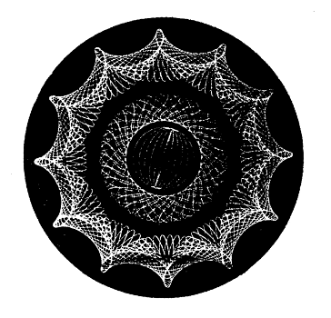
I give a few specimens, not for the beauty of design, but to illustrate the working of the engine. The centre of Fig. 407 is performed by having a wheel of 80 teeth on the upper mandrel, connected with one of 25 teeth on the intermediate spindle, which has another of 50 teeth connected with the large wheel of 192 teeth on the lower mandrel; thus,
80
25 50 =11/5
190
producing on each revolution of the lower mandrel one wave, and one-fifth of another wave, requiring six revolutions to complete the pattern.
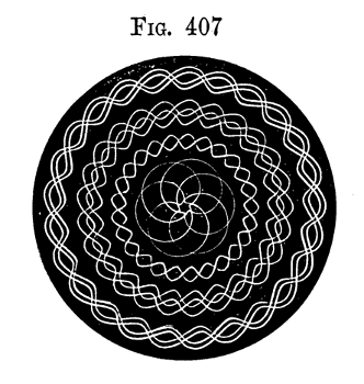
Fig. 407.
The remainder of the pattern is completed by wheels, 16, 50; 48, 192 making 12½ waves on each revolution of the lower mandrel, requiring 25 waves to complete the pattern, and laying the waves over each other, and with the slide rest movement of the tool.
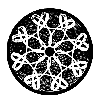
Fig. 408 is produced by wheels 32, 48; 24, 192 making 12 waves. The centre is done by altering the eccentric chuck each time. It was purposely executed askew, by the tool not being placed in the centre, to show the importance of doing so for some patterns. The rim was executed with the same wheels, and with the slide rest movement of the tool, and, after two cuts, the chuck turned half round, to lay the waves over each other for the other two cuts.
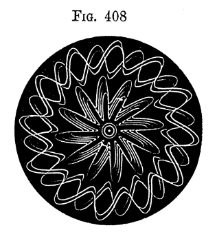
Fig. 408.
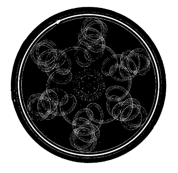
Fig. 409 is all executed with wheels 96, 30; 25, 192 making two waves and two-fifths of another wave, requiring 12 waves to complete the pattern. The two centre rims produced by placing the tool above the centre. The outside by four movements of the slide rest tool, illustrating how soon patterns are produced, and when well cut up look very pretty.
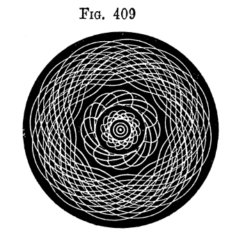
Fig. 409.
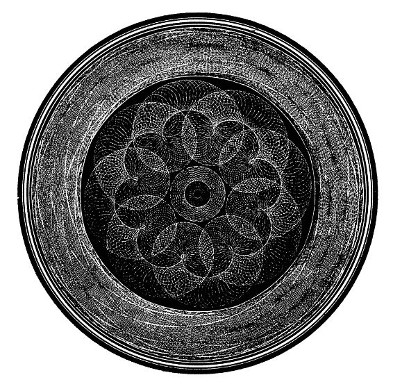
Fig. 410 is executed with wheels 80, 50; 25, 192 making four waves and four-fifths of another wave, requiring 24 waves to complete the pattern. The centre is all done without stopping; the outside rim by altering the eccentric chuck four times, to make each successive wave flatter.
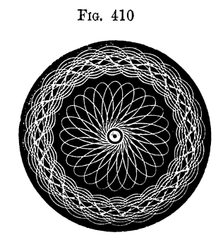
Fig. 410.
Fig. 411 is an illustration of the upper mandrel, making 5⅓ revolutions to one of the lathe, requiring 16 revolutions to complete the pattern and slide-rest movement.
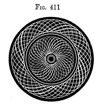
Fig. 411.
Fig. 412. The outer pattern of this figure is produced by the upper mandrel making 12⅘ revolutions to one of the lathe, requiring 64 revolutions to complete the pattern. The centre is a rosette of 5 waves, slide-rest movement and placed across each other.
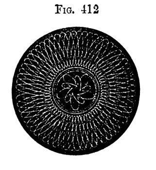
Fig. 412.
Fig. 413. The whole of this pattern produced by the upper mandrel making 3⅗ revolutions to one of the lathe, producing 18 waves across each other with slide-rest movement for the middle rim.
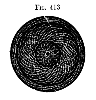
Fig. 413.
Fig. 414 illustrates a rosette of nine waves with slide-rest movement, and 3 divisions of the circular movement of the eccentric chuck for each successive line, producing the waved appearance.
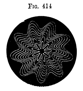
Fig. 414.
Fig. 415 illustrates a rosette of 24 waves with the slide-rest movement.
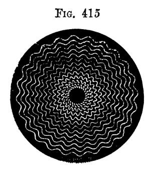
Fig. 415.
Fig. 416. Another illustration of a rosette of 24 waves, rather more sharp than in Fig. 415, with slide-rest movement and 9 divisions of the circular movement of the eccentric chuck, giving it a pleasing circular waved appearance.
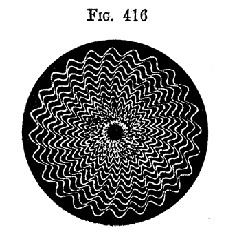
Fig. 416.
Fig. 417. Also another illustration as the last, but with the waves much sharper, the slide-rest movement and only two divisions of the circular movement of the eccentric chuck producing the star-like pattern.
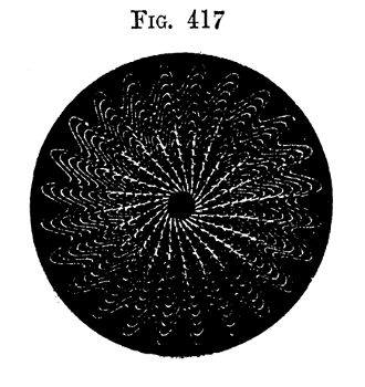
Fig. 417.
Fig. 418 illustrates also a rosette of 24 waves, with the eccentric chuck turned half-way round with each movement of the slide-rest, producing the pattern so often seen on the back of watches, only being on wood it is on a larger scale.
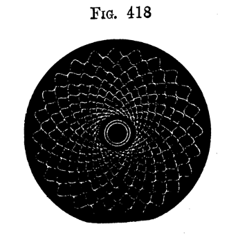
Fig. 418.
The above illustrations are sufficient to give a distinct idea of the working of my engine, and the last four show how easily patterns are multiplied and varied.
The whole of the preceding patterns were executed by the wood being chucked in the lathe in the usual ordinary way without any particular chuck whatever, but in combination with any of the ornamental chucks innumerable patterns can be produced.
Fig. 419 is one illustration with an eccentric chuck on the lathe mandrel.
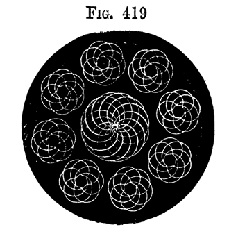
Fig. 419.
That my description may be complete I will now give drawings of my eccentric chuck for the upper mandrel. It requires to be constructed differently to the ordinary eccentric chuck, as the circular movement requires to be always central, and only the slide carrying the pin to receive the rod must move eccentrically.
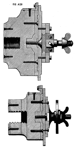
Fig. 420, also 422.
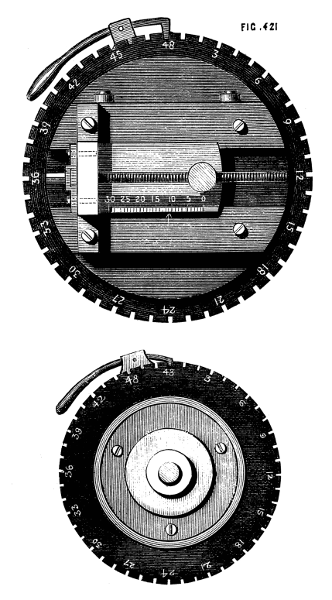
Fig. 421, also 423.
Figs. 420 and 421, are full-size drawings of my eccentric chuck on my upper mandrel, used for producing the foregoing specimens. In this case I have preferred a wood foundation, as not being so likely to run off as metal, on reversing the motion which is sometimes necessary on account of idle wheels for the connections. I used a piece of well-seasoned Spanish mahogany, taking care that the grain of the wood was at right angles with the length of the screw of the mandrel. A piece of brass is screwed at the back to prevent the screw cutting into the wood. Fig. 420 is a section, and Fig. 421 a front view of the chuck, and I think all sufficiently clear. I will just say the long fine threaded screw I cut up with the stocks and dies in the lathe, using steel wire of the necessary size. This I manage easily, and keep the wire straight by allowing it to expand in length. I chuck the steel wire concentrically, and removing the centre from the back poppet, substitute a brass centre with a hole the size of the steel wire, which is allowed about a quarter of an inch entry. I then turn down a little below the depth of the intended screw thread for about half an inch in length next the back centre, to allow the dies to come back to be tightened up, and which must only be done at the commencement and not on the return motion of the dies. The collar on the screw is a piece of brass with a hole of a size to drive on the wire tight, and is then pinned on and turned up true, and finished with the division marks.
Oval Turning and Rose Cutting with Templates with my Apparatus.
Figs. 422 and 423 are full size drawings of my chuck, with circular movement for templates for my upper mandrel, which has also a wood foundation. Fig. 422 is a section, and Fig. 423 is a front view.
By removing the eccentric chuck from the upper mandrel, and substituting the chuck Figs. 422 and 423 with a circular movement, to receive templates of any pattern, ovals with the oval template can be turned and also with any irregular templates, patterns cut and placed in any direction over each other, by causing the templates to work against a rubber or roller as most desirable, with an india-rubber spring to keep them together.
The following illustrations will give some faint idea of productions from templates.
Fig. 424, is the production of an oval template and slide-rest movement, both mandrels making equal revolutions.
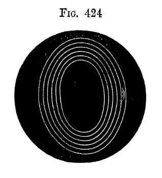
Fig. 424.
Fig. 425 the same as Fig. 424, with the patterns laid across each other by turning the circular movement of the chuck 12 divisions.
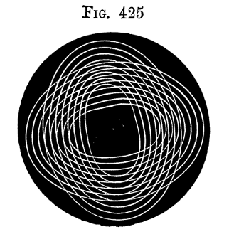
Fig. 425.
Fig. 426, is from an oval template, which is caused to make two revolutions to one of the lathe mandrel producing 4 waves and undulations and with the slide-rest movement. It will be perceived in this case the form of the oval is superseded by another pattern, and shows how great a change in the form of patterns from templates my rose engine with change wheels effects.
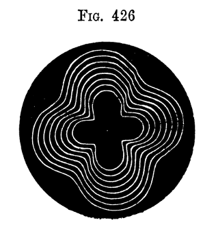
Fig. 426.
Fig. 427, is also from an oval template, caused to make 5 revolutions to one of the lathe, and with the circular movement of the chuck and the slide-rest movement, and in this case the form of the oval is also superseded. Indeed, none but those who have made the matter their study would have the slightest idea that this pattern could be produced from an oval template.
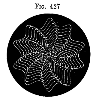
Fig. 427.
Fig. 428, is also from an oval template, it is finer than 427, but is done in the same way by the template making nine revolutions to one of the lathe mandrel.
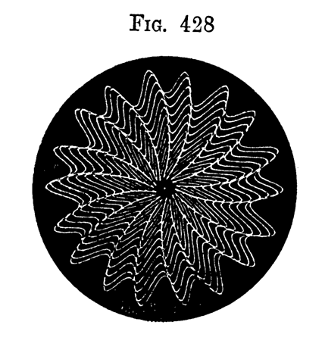
Fig. 428.
The above are a few specimens of the oval, but sufficient to draw attention to the great variety of patterns that can be executed, and these illustrations have only been made to go even revolutions with the lathe mandrel; but of course can be made to go, as already described, uneven revolutions, laying the lines over each other for variety of patterns.
Fig. 429, is a curiosity from a square template with equal revolutions, the outside rim and inside pattern by the circular movement of the template chuck.
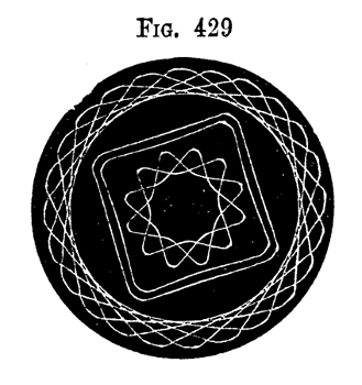
Fig. 429.
Fig. 430, is also from a square template made to go two revolutions to one of the lathe and with the slide-rest movement. The centre pattern with the circular movement of the chuck.
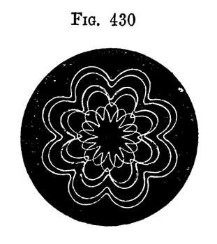
Fig. 430.
Fig. 431, is the production of a heart-shape template, and with the slide-rest movement and the patterns laid across each other, the mandrels making equal revolutions.
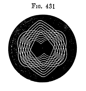
Fig. 431.
Fig. 432, is also from a heart-shape template made to go two revolutions to one of the lathe and the slide-rest movement. But in this case the slide-rest tool is used on the opposite side of the lathe bed to the roller against the template, and therefore reversing the pattern, that is, the projections of the pattern are the hollows of the template, and vice versa. I have introduced it to show how easily patterns are multiplied in the most simple way. It will also be observed that the form of the template is superseded.
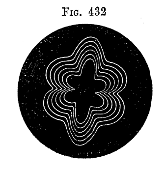
Fig. 432.
Fig. 433, is another illustration of the heart-shape template, but made to go five revolutions to one of the lathe, with the circular movement of the template chuck, and the slide-rest movement, and in which case the form of the template is entirely superseded.
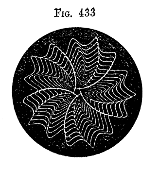
Fig. 433.
Fig. 434, is also a similar illustration to 433, only finer; they can be of course as fine as desired.
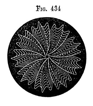
Fig. 434.
The above are, I think, sufficient to illustrate the productions from templates, some very pretty patterns can be executed. My object is more particularly to exhibit the use and extended application of my rose engine, and it will be perceived the last two are not the most easily working templates.
The variety of patterns that can be executed with this engine are so innumerable that one may say they are infinite. Well may you in your article quote what Bergeron says of the rose engine, "that it is necessary to know thoroughly the particular one in use."
I also make use of the cogwheel on my mandrel, by connecting it by a spindle and the change wheels with a large compound slide rest, for executing spiral turning, and also with my slide rest for ornamental turning, for small spiral work; and with a chuck with a circular movement I can cut several spirals to one stem.
In concluding my description I will say the specimens given have all been cut on a plain surface, and this has been unavoidable on account of printing, but for the information of those unacquainted with the rose engine, the very great advantages of which over the eccentric and geometrical chucks are that the work can be executed on concave or convex surfaces. I make use of mine for ornamenting the roofs of temples and Chinese pagodas, either domed, curvilinear, or circular pointed, by representing them covered with shingles, &c. The geometric chuck will produce very beautiful intricate lacework, but not more so than my apparatus, as they both are on the same principle of change wheels, and can both produce equally fine work; but with my apparatus the work is always concentric with the mandrel, and therefore much more pleasing to execute.
Elias Taylor.
Hartford Villa, Patcham, near Brighton, Sussex.
Judd & glass, phœnix printing works, doctors' commons, e.c.
ADVERTISEMENTS.
ESTABLISHED A.D. 1822.
JAMES LEWIS.
41, GREAT QUEEN STREET, LINCOLN'S INN FIELDS,
(Late Lewis & Son, of Wych Street, Strand),
Engineer, Machinist, Lathe and Tool Maker, and Modeller of New Inventions, for English or Foreign Patents, from Drawings or Specifications, in Brass, Iron, or Wood.
Also Manufacturer of Steam Engines and Boilers for driving Amateur Lathes, Pleasure Boats, &c., the Boilers fitted with Messrs. Field's Patent Circulating Tubes; whereby a great saving of Fuel and space is effected; or can be fitted for Gas.
Model Steam Engines and Boilers kept in Stock, and the different parts may be had for making the same.
Estimates given for all kinds of Work. Country Orders punctually attended to.
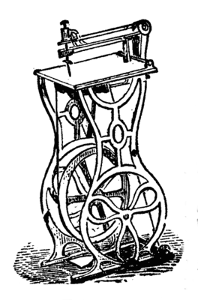
JOSEPH LEWIS'S.
PATENT
COMBINED DRILL, CIRCULAR SAW,
AND FRET MACHINE.
Patterns and designs for Picture Frames, Brackets, Reading Desks, etc., from 3d. each, or 2s. 6d. per dozen assorted.
To fix on Lathe £3 0 0
Ladies' Machine 4 0 0
Ditto ditto 5 0 0
Gentlemen's ditto 5 0 0
Ditto, with drill 6 10 0
Gentlemen's Machines with Circular Saw 8 0 0
Ditto, ditto, ditto, with the improved Saw-shifting Apparatus complete 9 10 0
Best Saws from 4½d. per doz., 4s. per gross. Ornamental Drills from 1s. each.
51, HIGH STREET, BLOOMSBURY.

JOSEPH LEWIS,
ENGINEER, MACHINIST, LATHE AND TOOL MAKER, AND MODELLER OF NEW INVENTIONS.
Manufacturer of every description of Plain and Ornamental Lathes, Chucks, Slide Rests, Tools, Drills, over-hand motions, Division Plates, &c.
Lathes £8 0 0, £10 0 0, £12 0 0, £14 0 0, £16 0 0, £25 0 0.
Amateurs supplied with Castings, Forgings of Lathe Engines, &c., and assisted in making the same.
JOSEPH LEWIS'S
Apparatus for cutting Screws of all nitches, self-acting, made and fitted to any Lathe.
51, High St., Bloomsbury, London.
JAMES MUNRO,
(From Messrs. HOLTZAPFFEL & Co.)
ENGINEER, MACHINIST,
LATHE AND TOOL MAKER,
MANUFACTURER OF ALL KINDS OF
LATHE APPARATUS FOR PLAIN OR ORNAMENTAL TURNING,
DIE STOCKS, TAPS, SCREW TOOLS, OVAL AND ECCENTRIC CHUCKS, CUTTING FRAMES, &c.
4, GIBSON STREET, WATERLOO ROAD,
LONDON, S.
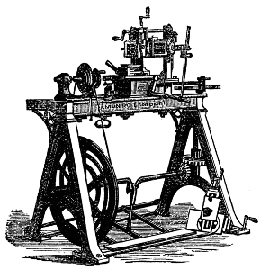
MACHINE TURNING LATHE FOR PLANING, ETC., ETC. INVENTED BY J. MUNRO.
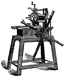
HAND PLANING MACHINE.
James Munro respectfully invites the attention of Amateurs and Manufacturers to the excellence of workmanship and construction of the various descriptions of Lathe Machines and apparatus produced in his manufactory, which has secured the approval of numerous patrons.
Specimens may be seen at the Museum of Patents, South Kensington.
THE ENGLISH MECHANIC
And Mirror of Science,
IS AN ILLUSTRATED RECORD OF
Engineering, Building, New Inventions, Photography, Chemistry, Electricity, &c., &c.
Weekly, price 2d.; post 3d. Monthly parts, 9d.; post 11d. Quarterly Subscription, post-free, 3s. 3d. Vol. VI. now ready, 7s.; post-free, 8s.
(From the Weekly Times.)
"Technical education forms just now a topic of more than ordinary importance, and, as far as we can see, 'The English Mechanic' fills a large space in providing technical food for the workmen of Great Britain. There is scarcely a subject in the scientific or mechanical world that is not practically described in this excellent journal, and all the technicalities explained with a particularity quite remarkable. Here the workman in all departments of trade will find something to interest him, and many things explained by which he will be able to make the best use of his knowledge. The editor is always anxious to satisfy the cravings of his readers by giving every information possible to those who may require it. The trouble taken in this department is apparent on reference to the 'Letters to the Editor' and 'Replies to Queries,' both of which form original, very important, and useful features of the magazine. Under the head, also, of 'Our Subscribers' Exchange Club,' a means is opened for persons to exchange one article for another on mutually advantageous terms, and for this accommodation no charge is made. For instance, one correspondent says he has a silver watch which he would exchange for 'The Lives of Eminent Men;' another wants 'a cottage piano' for 'a three-horse power horizontal engine;' and a third has 'a hand sewing machine,' which he would give for 'a parallel sliding vice.' The illustrations of 'The English Mechanic' are worthy of all praise; they are drawn with an exactness which is so necessary, and so much appreciated by workmen, and are also well printed. Throughout the whole publication there is a visible, a practical, and technical knowledge of a high order—a kind of knowledge that is highly prized by all mechanics and men of science."
(From the Morning Advertiser)
"'The English Mechanic.'—Illustrated with appropriate engravings, this valuable periodical is replete with information of the most valuable kind in every department of engineering, and in all applications of the principles of physical science. Its contents are exceedingly varied, and embrace, in a form adapted for immediate and convenient reference, a well-digested account of any noteworthy progress made in the mechanical or chemical arts, at home or abroad. For all purposes of the inventor, we do not know a periodical more likely to give him that assistance which he could expect to derive from recent means and appliances."
(From the Observer.)
"'The English Mechanic and Mirror of Science' is a publication which contains much that is new and instructive in various branches of science."
Now ready, price 9d.; post free, 10d.
THE ENGINEER'S SLIDE RULE, and its APPLICATIONS. A complete investigation of the principles upon which the Slide Rule is constructed, together with the method of its application to all purposes of the Practical Mechanic.
Published by the Proprietor, Geo. Maddick, 2 & 3, Shoe Lane, Fleet Street, And to be had of all Booksellers.
ESTABLISHED A.D. 1810.
W. J. EVANS,
ENGINE, LATHE AND TOOL MAKER,
AND GENERAL MACHINIST,
104, WARDOUR STREET, SOHO, LONDON.
TURNING, PLANING, SCREW AND WHEEL CUTTING TO DRAWINGS AND MODELS.
Amateurs' turning Lathes of every description for Plain, Eccentric, Oval and Ornamental turning, also the various tools and apparatus the Mechanical Arts.
Instruction given to Amateurs in Plain and Ornamental Turning in all its Branches.
Contractor to Her Majesty's War Department.
LATHES,
AND EVERY DESCRIPTION OF TOOL FOR AMATEUR TURNERS.
Lathes complete, £7 5s., £9, £11, £16 16s.
CHUCKS & ALL KINDS OF APPARATUS FITTED TO LATHES.
Engineers' Files and Tools of every description.
AMERICAN TWIST DRILLS,
And Self-centering Chucks for holding all sized Drills.
AMERICAN SCROLL CHUCKS OF ALL SIZES
Can be readily fitted to any Lathe.
JOSEPH BUCK,
124, NEWGATE STREET, E.C.,
And 164, WATERLOO ROAD, S., LONDON.
W. BLACKETT,
HOPE IRON WORKS,
SOUTHWARK BRIDGE ROAD, LONDON,
MANUFACTURER OF
Engineers, Millwrights, Iron Ship Builders, and Boiler Makers' Tools.
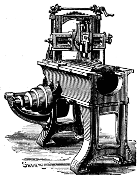
PLANING MACHINE.
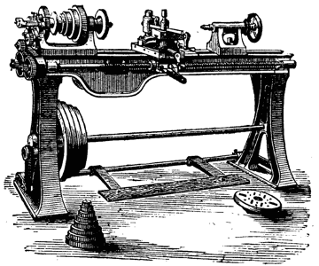
SCREW CUTTING FOOT LATHE.
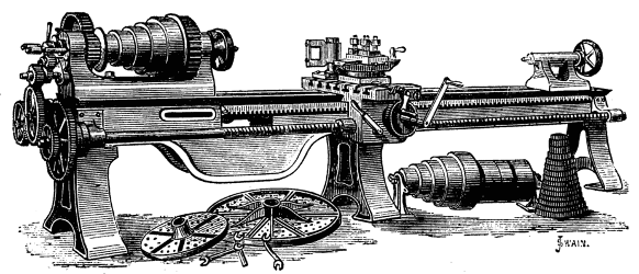
SLIDING AND SCREW CUTTING LATHE.
The Machines usually on hand consist of large and small Boring and Drilling Machines; Universal Shaping, Planing, Slotting, Bolt-screwing, Single and Double ended Punching and Shearing Machines; a variety of Self-acting, Sliding, and Screw-cutting Lathes, Hand Lathes, Foot Lathes, Compound Slide Rests, Planed Iron Lathe Beds, Ratchet Drill Braces, Screwing Tackle, Screw Jacks, and other Tools, such as are usually required in Engineering Establishments. Tools not in stock made to order.
By Her Majesty's Royal Letters Patent.

CUNNINGHAM AND CO.,
480, NEW OXFORD STREET, LONDON, W.C.,
ORNAMENTAL WOOD
AND
METAL CUTTING MACHINES,
AND
DRILLING APPARATUS.
ADAPTED FOR LADIES' USE.
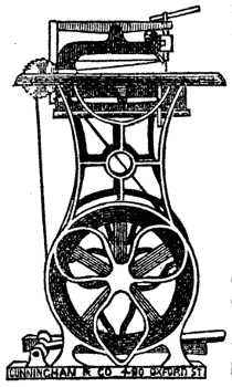
Useful to the following Trades—Organ Builders—Cabinet Makers—Pattern Makers—Chair Makers—Gun Case Makers—Marqueterie Makers—Toy Maker—Jewel Case Makers—Carvers—Cutlers—Leather Cutters—Engravers—Jewellers—Chandelier Makers—Electrotypers—Stereotypers—&c.
Will cut Brass a Quarter inch thick with ease.
The working of the Machine is very simple, and can be learnt by an amateur in five minutes.
Patentees of the CAM ROLLER BUFFING, FOR Preventing Noise in Machinery. See ENGINEER, Jan. 24th, 1868.
W. J. CUNNINGHAM AND CO.
Beg to call the attention of the Public to their newly-invented Ornamental Wood and Metal Cutting Machine. Its extreme simplicity of construction precluding the possibility of speedily getting out of order, having no springs, and its peculiar adaptability to all kinds of fret-work render it at once an acquisition and an indispensability where accuracy, expedition, and high finish are required. The working is exceedingly easy, requiring no more exertion than an ordinary Sewing Machine for ladies' use, and making as little noise. Its great utility, combined with neatness of construction, fits it not only for the workshop, but the drawing-room of the amateur. The saw takes the place of a pencil in the hands of the operator, enabling him to produce the most elaborate artistic designs in wood-work. Box or other hard texture woods, 1 inch thick, are as readily sawn through as the finest veneer; metallic plates of ⅛ inch thick are also speedily pierced. Magnificent specimens executed by this machine, which have been universally admired for their extreme delicacy and perfection, and acknowledged to be unrivalled, may be seen at the inventor's address. The length of stroke of the saw can be varied to the work in hand. A simple mechanical contrivance is attached for blowing the sawdust from the saw whilst working, also a Circular Saw.
An equally valuable invention is W. J. C. & Co.'s Patented Drilling Apparatus which is with the greatest advantage combined with the Sawing Machine, enhancing and enlarging its range of usefulness, or it may be adapted to a lathe, or as a distinct machine. Its great advantages over the ordinary lathe for drilling purposes must be apparent when by the addition of this apparatus to a 5 inch centre lathe the operator is enabled to drill in the centre of three or more feet, and the drill being vertical and worked by leverage, greater accuracy and facility is ensured. For ornamental purposes it surpasses all hitherto contrived methods, not being limited to one centre around which to describe curves, angles, circles, or any other mathematical figure, the operator is at perfect liberty to describe every conceivable device the fancy can dictate.
Advantages and Capabilities of this Machine.
This Machine can be adapted to any Lathe, see page 131.
This Machine has a Circular Saw.
This Machine has a Vertical Saw.
This Machine has a true Parallel Motion.
This Machine has no Springs whatever.
This Machine has a Bead and Moulding Apparatus.
This Machine has a Planing Apparatus.
This Machine has a Drilling and Grooving Apparatus.
This Machine has a Kinography that will engrave hundreds of different patterns on wood or metal.
This Machine will cut Spirals and Ovals.
This Machine has a Pentagraph, for reducing, enlarging, and cutting on the face of wood any drawing from paper or fret-work.
Circulars and all particulars on application.
Every kind of Materials, viz., Saws, Fret Patterns, Fancy Wood Drills, Cutters, &c., kept in stock.
MANUFACTURERS OF TURNING LATHES.
AND ALL KINDS OF MECHANICAL TOOLS.
MOSELEY AND SIMPSON,
Late 17 & 18, KING ST.JOHN MOSELEY & SON, 17 & 18, KING ST. AND 27, BEDFORD ST., COVENT GARDEN, LONDON, W.C. ESTABLISHED 1730.
LATHE AND
TOOL MANUFACTURERS,
&c., &c.
PRICE LIST OF LATHES.
Turning Lathe, Iron Frame and Bed planed true, Wood Tool Board, Iron Cone Mandrel, Cylinder poppet head, Rest and two Tees, Turned Grooved Wheel Crank, Treadle complete with 3 Chucks:—
No. 1. 3½ inch centre, and 2 foot 6 inch Bed £10 10 0
" 2. 4½ " " 3 " Bed 12 12 0
" 3. 5 " " 4 " " 15 15 0
" 4. 5 " " 4 " "
with Brass Pulley and Slide Rest 21 0 0
" 5. 6 inch centre and 4 feet Bed with Slide Rest complete 25 0 0
" 6. 7 inch centre, 6 feet Bed, self-acting, and
Screw Cutting leading Screw, and 22 Change Wheels 40 0 0
For Lathes of other descriptions, Estimates are furnished on Application.
TURNING TOOLS.
s. d.
Chisels for Soft Wood, the set of 6 handled 8 0
Gouges 9 0
Tools for hardwood and metal, handled and ready for use, per dozen 15 0
Drills handled 0 7
Arm Rests Handled 2 6
Callipers from 1 0
Turner's Squares from 6 0
All Kinds of Chucks, Cutters, &c., made to order.