THE LATHE AND ITS USES. (continued 5)
Reading edition
This handy apparatus will be found on a later page fully described and illustrated by a photograph of the machine. The writer has seen it and used it, and can testify to its satisfactory working, as a lathe thus fitted does not run heavier or require greater exertion than when used for ordinary turning.
The next step will be the chamfering of the edges of the plate. Let 235 represent the plate in its present condition, with rectangular edges. To produce a chamfer of 45°, draw a line, a, b, at a distance from the edge equal to the thickness of the piece. If a smaller angle is desired, the line must be drawn further back. An angle of 30° to 35°, is, in the writer's opinion, better than one of 45°, as the chamfered bars will then have a wider bearing on the upper surface of the plate, tending to hold it more securely down upon the lower part of the chuck. Nothing remains but to file carefully down from the line thus drawn to the lower edge, by no means a difficult operation if care is exercised not to obliterate the mark, or to trespass the least beyond the assigned limit. A template, cut like Fig. 236, of the desired angle, will be a gauge for the edges of the plate, as well as for those of the chamfered bars, and will serve to make assurance doubly sure. The arms which stand out at the back of the slider to embrace the guide ring are not fastened to the plate immovably, but with power of adjustment. A pair of short slots are made in the slider, into which a square projection from the arms fits, and the whole is clamped by a screw, as shown in 237, A, B, and C.
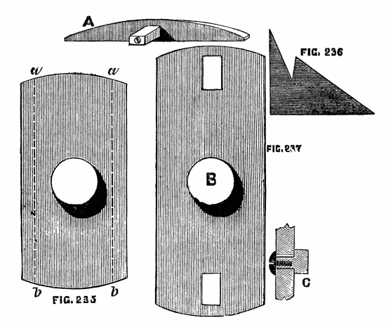
Figs. 235, 236, 237.
A more accurate method is shown in the Ornamental Section for finer adjustment than can be secured in this way, but for a home made chuck the above will suffice and is the easiest plan to carry into effect. To use this chuck, the guide is first arranged, so that its ring is concentric with the mandrel. A mark is generally made upon it, and also upon the lathe-head, by which this position can be readily insured. The chuck is then screwed upon the mandrel, and the arms adjusted, as just described, so as to embrace accurately, but not too tightly, the guide ring. They are then, once for all, fixed in that position by the screws alluded to. A few drops of oil are necessary to lubricate their inner surface and the exterior of the guide, and the latter being withdrawn by its adjusting screws to the desired eccentricity, the work may be proceeded with. A rough piece of wood, however, should always be first turned to a cylindrical form, as an oval chuck being an expensive article is to be carefully preserved, and not exposed to the shocks inseparable from the process of roughing down the work. Moreover, there should always be one or two screws passing through the slider into the back plate, to take away the strain from the chamfered bars, which can be removed when the slider is to be brought into action. Two precautions are here laid down respecting oval turning, which, in all probability, a tyro would not suspect to be necessary until taught by failure. In the first place, at whatever point of the circumference the tool is held, at that point it must remain, or rather, it must remain in the same horizontal line, being neither raised nor depressed. Hence, for all work where accuracy is needed, oval turning should be done with the slide rest. In the second place, when it is desired to place a succession of ellipses one within the other on the face of the work, like Fig. 229, it will not be sufficient to place the tool nearer to the centre for each ring, but the eccentricity of the guide ring must be reduced at the same time; otherwise, when the middle is reached, a straight line will be the result, instead of the proposed ellipse, as already stated. The lathe should not be driven at a very high speed, and the moving parts should be lubricated from time to time. There are other ways of compensating the error produced by the oval chuck, or elliptic cutting frame, which however are so entirely connected with ornamental turning that they are reserved to be introduced into that section. A contrivance for turning ovals invented, and communicated to the English Mechanic by a Suffolk amateur, deserves a place here. It is thus described by the inventor:—
Turning Ovals, etc., by Means of a Template.
Ovals are generally turned by causing the work to move in and under guidance of an "oval chuck".
There seems no reason why the same result should not be arrived at by communicating a movement to the rest supporting the cutting tool in the following manner:—Let A, A, be lathe bearers, B, pulley, C, screw of mandrel, D, template fixed thereon, E, friction wheel on the end of bar F, G rest (a board of any convenient width) moving on pivots at H. The friction roller, E, is to be kept in contact with the template by the cord running over the pulley T, stretched by the weight L. The rest will thus oscillate under the guidance of the template, which may be either oval or rose engine pattern, and the cutting tool form the pattern of the template used. There might be other modes of causing the rest to oscillate on the same principle. The lathe would require a slow motion, the same as with an oscillating mandrel.
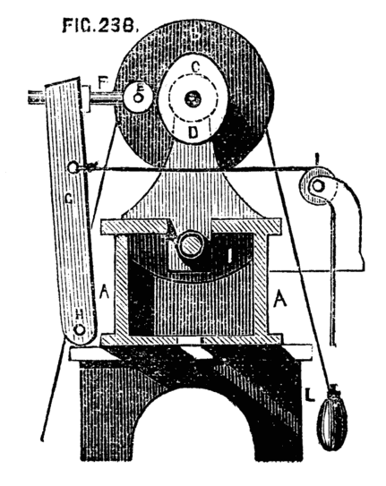
Fig. 238.
Eccentric Chuck.
Next in order of the compound chucks stands the eccentric, the use of which is not entirely confined to mere ornamentation, as it is often very convenient to the turner to have the power of shifting the centre of his work. Thus, a solitaire board may be drilled with the necessary cup-shaped holes, or any work of a similar character completed by the help of this chuck without the necessity for constant re-centering. The general work of the chuck in question is nevertheless ornamentation, for which it is peculiarly adapted either alone or in combination with other compound chucks, or overhead apparatus. The sliding plate of this chuck works between chamfered steel bars, the same as in the oval chuck. There is, however, no guide ring on the lathe head to regulate the movement of the slide, and therefore also no necessity for the projecting arms at the back. The slide, in fact, is moved by a screw with a graduated head, similar to those already described. Fig. 239 represents the common form of this chuck, in which the wheel which forms a dividing plate is moved by a tangent screw. The sliding plate is shown slightly drawn out by its screw, the degree to which it is moved being that of its required eccentricity. When the plate is drawn back to correspond with the base plate, the centre will be in a line with that of the mandrel, and any work turned upon the chuck in this position of the slide will be cylindrical. The central screw of all these compound chucks being alike and of the pitch of that on the mandrel, any of the ordinary cup chucks can be used with them to hold the work; or the eccentric chuck can be screwed to the elliptic, cycloidal, or any other in the set, by which means an endless variety of curves can be described. The effect produced by the simple eccentric chuck now described is as follows, the slide rest being used with it as a matter of course. Let a piece of box or other wood be fixed by means of a cup or other chuck upon the screw of the eccentric chuck, and the slide rest with a single point tool be brought in front of it. By means of this the work must be carefully faced, and made uniformly level. A ring A, Fig. 240, may now be cut, which will be concentric with the mandrel. The slide of the chuck being now drawn down by a few turns of the leading screw (the tool and rest being kept in its original position), the centre of the work will thereby be shifted, and the tool being advanced to touch the same, the circle B will be formed of the same size as the first, but necessarily cutting it at two points. Another turn of the screw will enable C, and similarly D, or any number of circles to be successively formed. The centres of these circles will be in a line across the face of the work. The ratchet wheel is added to enable the turner to arrange his circles round a common centre, instead of being thus obliged to keep them in a right line, and it will presently be seen what a beautiful variety of interlaced circles can thus be accomplished. The dividing wheel is, as previously explained, divided on its edge into an equal number of teeth, or racked for a tangent screw and divided on the face and edge. We shall suppose the number of divisions to be 120. Face the work afresh, and, drawing back the slide until the centre is concentric with the mandrel, as at first, cut a boundary circle, A, Fig. 241. Move the slide of the chuck a few turns, as before, and cut an eccentric circle. Now move the dividing wheel thirty teeth, and cut a second, and, advancing by thirty each time, cut a third and fourth, and Fig. 241 will be the result; the centres of the eccentric circles falling upon four points of the inner dotted circle, which is itself concentric with that first made.
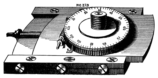
Fig. 239.
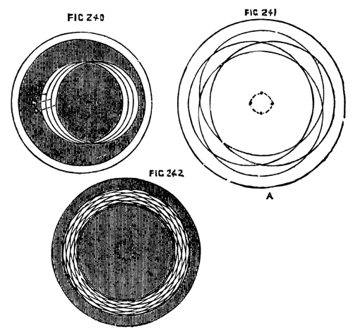
Figs. 240, 241, 242.
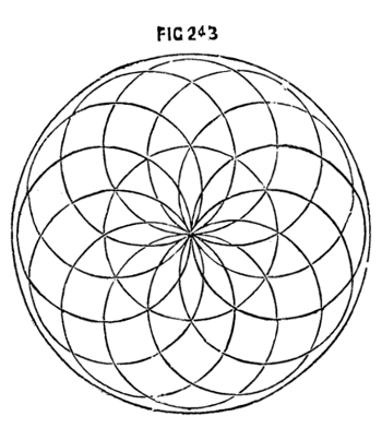
Fig. 243.
If the same process is followed, but the number of the circles increased, a very neat snake-like ring will be formed, constituting a border, in the inside of which other combinations may be made. In Fig. 242, twelve interlacing circles are shown; in Fig. 243, twelve circles, described upon centres, which lie upon the circumference of a central circle of equal size. This last pattern, when more finely executed, by doubling or trebling the number of eccentric circles, forms the device generally cut upon watch cases, under the name of engine-turned. The best way to try patterns, is to cover the face of a piece of boxwood with paper, using a pencil in the tool-holder of a slide rest instead of a cutting tool. If a softer disc is used instead of box, round pieces of paper or thin card can be fixed upon it with ordinary drawing pins; and if the first pattern is unsatisfactory, a second, and any successive number of pieces, can be mounted, and fresh patterns traced by the same means. It would be mere waste of time to multiply specimens of the patterns that may be executed by the aid of the chuck just described; and, indeed, this could only be done by cutting in the lathe itself the blocks from which such specimens must be printed. For the present, at any rate, the principles only by which such devices may be executed will be given (as above,) and the designs will be left to exercise the ingenuity and taste of the reader.
It happens, moreover, that few as are the works devoted to the general principles and practice of plain turning, more than one has been published on ornamentation by the eccentric and other compound chucks, in which a variety of executed patterns appear, of more or less beauty; and in the English Mechanic has lately been printed a selection of exquisite designs by Mr. G. Plant, whose chuck, indeed (to be presently noticed), bids fair to supplant the most simple one now described. The chief recommendation, perhaps, in the latter, is its great simplicity, as it may be made by any amateur sufficiently practised in the use of tools; whereas the geometric chuck is too complicated to permit this. It will be observed, on inspecting the drawing, Fig. 239, that the divisions on the face of the wheel are continued on the side above the part that is racked; this permits them to be seen when the piece of work overlaps the circle of the wheel. The steel point shown at B, answers as an index, either to the surface marks, or to those on the side. The tangent screw is now generally fitted in a small frame, which is itself pinned at one end to the top plate, and kept up to the dividing wheel by an eccentric cam. This is not shown in the drawing; the plan is nevertheless good, as the screw is instantaneously released from gear at pleasure, when the wheel may be turned by hand to any desired position; after which a slight movement of the cam brings up the screw, and all is made ready for work. The eccentric chuck becomes available for such work as shown in Fig. 244, representing the bottom of a candlestick, ringstand, or similar article. In this case the centres of the eccentric work (now cut quite through) are on the circumference of a circle larger than, and outside, the work itself. Instead of cutting through the whole thickness of the stuff the outer circle may remain such, and the blackened part may represent an inner raised surface, when the contrast formed by the sharp edges round the pattern with the smooth circular part will be very agreeable to the eye. To improve still more this design, the outer part may be ebony nicely moulded and edged with ivory, and the raised part ivory; or the same may be alternations of ebony and holly, which will form a contrast almost equally agreeable. A small chisel-ended tool must be made for this work if the whole is in one block, as it will be necessary to leave a level surface upon the face of the lower part. There are an infinite number of designs of similar nature, which will occur to the reader when the principles of the chuck have been mastered, some of which would at first sight appear to have been worked by other means. Fig. 245, for instance, which is but a modification of the last, scarcely looks like lathe work, but can be cut more rapidly this way than any other—of course the fret saw will do similar work, but it would first have to be marked out, and afterwards the marks of the saw teeth removed, whereas the above is cut and polished at once. It may here be observed that the eccentric chuck itself is used to fix the position of the various circles to be cut, whereas the size of these circles is determined by the slide rest. Thus in Fig. 246, while the centre of the chuck is concentric with the mandrel, bring up the tool in the rest and cut the circle F, G, H, of which B is the centre; draw down the slide of the chuck until its centre is at C, leaving the slide rest as it is, and the circle F, E, D, will be formed of equal size with the first. Now move the screw of the slide rest so as to draw in the tool towards the centre of the lathe bed without altering the chuck, and the small circle will be the result, whose centre (being dependent on the chuck alone) is the same as that of the larger circle. Bearing in mind this principle, that the chuck determines the various centres only, and the slide rest the radii, little difficulty will be experienced in devising and executing designs. Such is the simple eccentric chuck, of which the use is tolerably extensive; but there are, nevertheless, certain positions in which the eccentric designs are required, which cannot readily be obtained by its means. Fig. 247 is one of these, in which a moment's inspection will show the necessity of two distinct movements of the slide at right angles to each other. Hence a second slide is attached to the first at right angles, much the same in effect as a second chuck screwed upon the first but standing across it. This is the compound eccentric chuck to be subsequently described in detail. There is one drawback to the use of these chucks, namely—their excessive weight, which causes a great deal of vibration in the lathe itself, especially when the eccentricity of the slide or slides is great. An accidental blow moreover from the chuck under the above condition would be very severe. Hence the various cutters eccentric and others, worked by the overhead apparatus already in part described are infinitely more pleasant to use and even more effective and more easily managed. The eccentric chuck can be used in combination with these, and the capabilities of the two will thus be vastly extended, but in this case the chuck is kept stationary while motion is given to the tool, and the defect just alluded to no longer exists. In cutting patterns upon hard wood and ivory a common defect is shallowness of work, the cuts should not be so light as to give merely an effect of a design scratched upon the surface. The cut should be deep and clean, and the tool not only sharpened but polished so as to leave the device boldly executed, the small triangular and other shaped pieces left between the cuts standing up clear and solid. Some patterns, as the shell, which will be presently spoken of, require to be deep at one part and shallow at another. Some devices look best when cut with a point tool with double and others with single bevel to the edge, and the same design worked with different tools will appear almost like two distinct patterns.
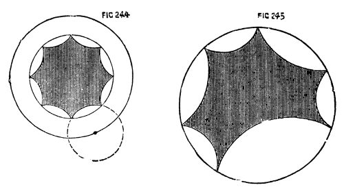
Figs. 244, 245.
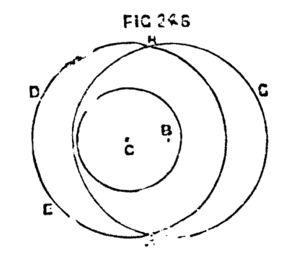
Fig. 246.
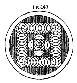
Fig. 247.
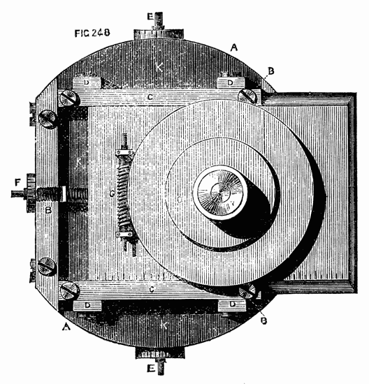
Fig. 248.
The double eccentric is represented in Fig. 248. The part A is the foundation plate, with a projection at the back, tapped to fit the mandrel. B, B, the lower guide bars; K, K, the lower sliding plate. All the above parts are precisely similar to those of the simple eccentric chuck. Upon the face of this lower slide are attached two chamfered guides, C, C, at right angles to the first. They are kept in place by screws passing through oval holes on their faces, and tightened when required by screws, tapped into four little square blocks, D, D. Between these guides slides the upper plate, which carries the screw for chucks, and the dividing wheel as before worked by a tangent screw, G; to either end of which a key is fitted. The leading screws, E and F, which move the two slides, have squared ends projecting both ways, so that the plates can be made to work eccentrically in either direction, which is sometimes an advantage. The chucks do not screw down upon the face of the division plate, on account of their projecting parts at the back; and very commonly a round plate, O, somewhat smaller than the wheel and about ¼ in. thick is attached to the face of the latter to raise the work still higher, so that the dividing plate can be readily seen. The more compactly, however, the parts of this chuck are made, and the less the work projects from its face the better; as there will be the less strain upon the central pin, and upon the plates and their guide bars when the tools are applied to the work.
To be able thus to place in the centre of rotation any given point in a piece of work, whatever may be the form of its boundary lines, is of immeasurable advantage, even though the capabilities of this chuck are confined to objects of plane superficies, it being impossible to reach by its means the side of a cylinder, or the surface of a sphere or spheroid. It is evident that any line upon the face of a box, for instance, whether the latter be square, round, octagonal, or of any other form, may be followed with two movements of the slides, combined with the rotatory movement of the dividing wheel. Thus, a border of interlacing circles may be carried round the edge of such a box, Fig. 248; or, a series of such circles forming constantly diminishing octagons, hexagons, squares, &c., may be thus readily executed. Nevertheless, what was said of the simple eccentric chuck, applies with even greater force to the compound eccentric. It is a heavy piece of apparatus, requiring a lathe with substantial poppets and bed; the whole well braced to the floor and wall, to withstand the excessive vibration caused by the revolution of the apparatus. It was, indeed, in view of this and similar appliances that we insisted in our initiatory paper upon the great importance to the workman, of adequate strength and solidity in the various parts of the lathe itself.
In Fig. 249, we give a simple specimen of work to be executed by the compound eccentric chuck.
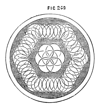
Fig. 249.
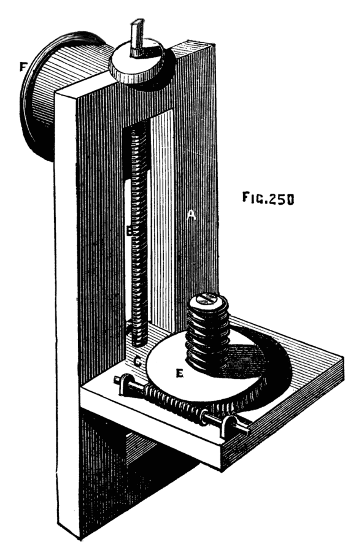
Fig. 250.
The compound geometric chuck of Ibbetson, manufactured by Holtzapffel and Co., is a double eccentric considerably improved and of very extensive application. A full description of it is published in a book written by the inventor, in which an immense number of patterns executed by its means is given with detailed directions for their execution. As these patterns are almost essential to a description of the apparatus as exemplifying the working of its several parts, the reader is referred to the book in question, or to a translation of it into French in the supplement to Bergeron's work. To enable the turner to execute patterns on the side of cylindrical pieces a chuck is used called a dome chuck, similar to Fig. 250. A rectangular frame of brass, A, carries a sliding plate C, at right angles to it, the latter having a tailpiece which fits accurately between the frame, and is tapped to receive the finely cut leading screw with divided head, B. A nut at the back of the frame clamps the slide in any desired position. Upon the upper face of the latter is a wheel racked on the edge so as to be moved by the tangent screw, E. This wheel, like that of the oval and eccentric chucks, turns on a strong conical central pin, and has a screw attached of the same pitch as that on the mandrel. The chuck is screwed to the mandrel by the projecting flange, F. The work is thus mounted at right angles to its ordinary position.
By this arrangement any point in the side of a cylinder can be brought in contact with a tool fixed in the slide rest, and by means of the graduated screw heads of the latter and of the chuck various devices can be accurately made. This chuck may be used alone or in combination with the eccentric, and the quick revolution of such cumbrous pieces that would be a great drawback to their use is less frequently required, now that the following apparatus has been added to the lathe, and eccentric revolving cutters, with drills and other tools, have taken the place of heavier and more inconvenient apparatus. It is indeed much more convenient in the majority of cases to keep the work itself fixed, and to operate upon it by tools put in rapid motion, because the latter, from their excessive velocity compared with that which can be conveniently given to the material, make better work, and at the same time from their lightness impart no tremor to the lathe while in motion. The cuts thus made are in consequence very clean and smooth, and free from those slight undulations apparent when any vibration takes place in the lathe itself. The different varieties of overhead apparatus have been already described and illustrated, and it only remains to describe more in detail the revolving cutter frame, drills, and other apparatus used therewith.
The following pieces fit into the top of the slide rest in what is called the tool receptacle, and are advanced to the work by means of a lever as already described. Fig. 251 is the revolving cutter frame, the spindle of which is put in rapid motion by a cord from the flywheel passing to the small pulley through the medium of the overhead apparatus, as shown in a previous page. For the purpose of cutting small intersecting circles, a forked drill, Fig. 252, or a crank formed drill, 253, will suffice, and if these are made to cut deeply the result will be a succession of hemispherical knobs or beads (these must not intersect). A drill like Fig. 254 will give a knob raised in steps, and it is plain that by cutting the end of the drill to a section of the required moulding the latter may be rapidly executed. The flat inch long cutters used with the geometrical chucks (when the work revolves instead of the tool) are, of course, made of a variety of forms upon the same principle. Cases of these drills and cutters beautifully finished are sold by all the leading dealers in turning lathes and apparatus. It is essential that these tools be kept very sharp, and that their cutting edges should be polished if first-class work is to be done. The difference in the appearance of execution is very evident when the cutter is thus perfect, as every cut bears a high polish, which cannot otherwise be imparted. Nothing can be applied to finish eccentric work except friction with a hard brush, and even this is much better avoided, as rubbing of any kind tends to round edges which should be kept sharp and to obliterate the finer and more delicate lines. It is likewise the best plan to finish with any particular tool all the work to be done by it without removing it from the tool holder for the purpose of sharpening. If, however, this is necessary the following contrivance must be used to insure the precise form which the cutter had at the commencement of the work. This being likewise necessary with respect to the fixed tools for ornamentation, the apparatus requisite in either case will be introduced here, the drawings and description being extracted from Holtzapffel's valuable work already alluded to.
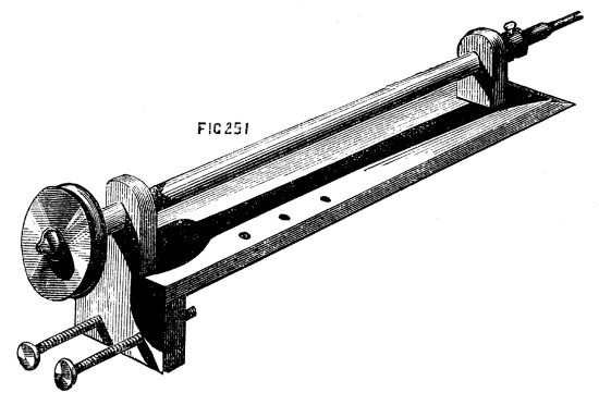
Fig. 251.
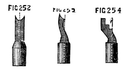
Figs. 252, 253, 254.
Fig. 255 is arranged for flat tools of various angles, or drills with single joints. A, is the stand of brass, with two turned and hardened steel legs. To this is hinged at G, by a screw joint, the part K, the upper part of which forms a semicircular arc, C. A second arc, B is fixed at one end to the stand A, and passes stiffly through a mortise at the top of K. The latter can be raised, therefore or lowered at pleasure upon this second graduated arc, and clamped at any angle by the screw H. To the lower part of K is pivotted the tool holder, D, the upper part of which is pointed, and screws as an index upon the arc C, showing the angle at which it is placed. This tool holder is clamped by a nut at the back, which fits the end of a screw seen near the point. The figure below shows a tool holder which fits into the projecting parts of D, and serves to hold the small flat tools. Below is a similar holder, used for round-shanked drills. F is one of three flat slabs upon which the tools are to be ground, there being one of iron, one of brass, and one of hard wood with a flat strip of oilstone imbedded in it, flush with its upper surface. The tool and its fittings are generally arranged in a box with three drawers; these contain the slabs of oilstone and metal, with the powders necessary for grinding and polishing. To use this instrument, the point of D is adjusted to the required angle for one side of the point of the tool. (It is shown at 40 deg. in the sketch.) The latter is then placed in the holder, and made to project until, when the angle of the chamfer is adjusted on the arc B, the part A is level, and therefore parallel to the surface of the grinding plate. The whole thus forms a tripod, the third leg of which is formed by the tool itself. The latter is first rubbed on the oilstone with a little oil. It is then finished more perfectly on the brass slab, dressed with oilstone powder and oil. Previous to this the tool is moved one or two degrees more upright by the arc B. A narrow facet is thus ground, having a dull grey polish. The tool is now carefully wiped clean, and polished with crocus and oil upon the slab of iron. If the point of the tool is central, with a chamfer both ways, the point of the tool holder is first adjusted on one limb of the arc and the tool ground, and then the same adjustment made on the opposite limb, so that the other side of the point can be operated upon. Thus tools of any angle and any bevel may be sharpened to a nicety without fear of altering the original form of the point, and this may be done, if necessary, during the process of eccentric turning, although, as before stated, it is better to fix the tools well sharpened at the commencement of the work, and not remove them until at least one complete set of circles or other patterns have been cut.
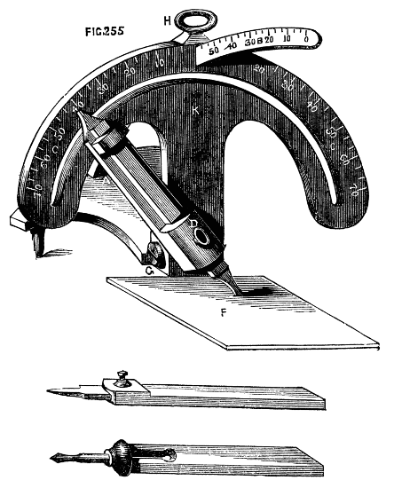
Fig. 255.
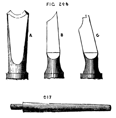
Figs. 246, 247.
The instrument just described is evidently unsuited for the drills and bead tools which present a concave edge like 246 A, B, C, enlarged sketches of tools copied from Holtzapffel's work. For these the latter directs to use large or small cones (247) of iron and brass, to be dressed, the first (which is the polisher) with crocus, the second with fine emery and oil, the flat side of the tool being held towards the point of the cone, the bevel towards the thick end. Part of the edge of C must be delicately sharpened by hand, as no guide can be used for the step-like portion of the edge. The cones for sharpening are either mounted in the usual manner, by one or both ends in the mandrel of the lathe, or fitted into the spindle of a small drilling lathe-head, the pulley of which is connected by a catgut band with that of the mandrel of the small lathe-head, being fitted with a tailpiece to fit the rest socket, or otherwise mounted on the lathe-bed. The smaller cones especially require to be driven at a high speed. When larger circles or mouldings are to be cut, these small crank-form drills are no longer available, and are replaced by a very simple, but most effective contrivance called the eccentric cutter, by which any work that is within the scope of the eccentric chuck and fixed tool may be executed with great precision and rapidity. This is represented in Fig. 248[20]—a small oblong frame of brass, about two or two-and-a-half inches in length, and half an inch or so in breadth is traversed by a fine screw, prevented from moving endwise by a collar, as in the slide rest (of which, indeed, this is a miniature). A slide, C, with a little tool holder at the top of it, is moved along the frame by the leading screw, the head of the latter being graduated, and also the upper surface of one or both sides of the frame. The projection A, fits into the end of the drill holder, and is secured by a screw. Circles of a diameter equal to B, B" may thus be cut, and their effect varied by placing tools of any form of edge in the tool holder. Such a tool as A, will thus no longer cut a minute circle forming a hemispherical raised knob, but will form a circular moulding, such as that shown in part at Fig. 249, except when the tool holder is on the middle of the frame and the tool concentric with the mandrel. The single point tools, however, with single or double bevel, are more commonly used, in this cutter, as mouldings can be turned as efficiently with hand beading tools, with or without the eccentric chuck, according to their required position. It may here be mentioned that eccentric work should always be cut on wood of one colour, or on ivory, as the veinings of the richer fancy woods, which are so beautiful in other cases, only serve to confuse the tracery made by the eccentric cutter. Of all woods for fancy work with the eccentric chuck or cutter, nothing equals African black wood. It is, however, costly, and only ranges to a diameter of five inches, as great part is unsound. The rind is hard, thick, and white, similar to boxwood. Next to this for such work stands, perhaps, cocus, or cocoa wood, which is not the tree bearing the cocoa nut, the latter being a palm, which is more like cane in texture. One of the most effective patterns to be formed by the eccentric cutter is the shell, Fig. 250, in which one side, or rather one portion of the circles composing it, is very deeply cut, while the opposite part is shallow. This can be simply effected by throwing the sole of the rest out of the level, by placing a thin piece of wood or metal across the lathe bed, so as to tilt up the rest and place it (with the cutter) in an inclined position. The tool will thus begin to cut at one part before it touches the surface elsewhere, and the desired effect will be readily produced. In using the eccentric cutter great rapidity of motion must be given to it, but the tool must be advanced very carefully, or it will be broken. The lever handle is the best to use for the purpose. Akin to the shell pattern are those in which part only of the circles are cut, leaving an effect shown by the border round Fig. 250. This is produced in the same way as the last, being, in fact, a ring of shells in their initiatory stages. This is a very effective snake-like pattern, when fairly and cleanly cut. When the eccentric cutter is used, it must be remembered that the principle of work is not quite the same as with the eccentric chuck. With the latter it was stated that the size of the circles depends on the slide rest and the position of their centres on the chuck. In the present case the eccentric cutter regulates the sizes, and the screw of the slide rest itself the positions of the centres of the circles, since the part A of the cutter will always be in the centres of the same, and this part is attached to the rest. It will be understood that this remark respecting position of centres only relates to circles lying on the diameter of the work, such as Fig. 251, the distance between a and b will be taken from the division plate on the pulley of the lathe. The way to cut the above, for example, will be as follows:—Place the slide rest so that when the cutter tool is in the centre of the frame it shall be concentric with the mandrel. In this position it will only make a dot in the centre of the work. Turn the screw of the cutter frame until you have a radius sufficient for the centre circle. Set the mandrel pulley with the index in No. 360, put in motion the overhead apparatus and cut the circle, move the screw of the slide rest a few turns (thus fixing the centre of the second circle), until you find that the cutter will form the circle cutting the first, and passing through its centre. (Observe, this being the size of the first, the screw of the cutter frame is not turned.) Cut the circle in question, move the mandrel pulley a quarter round, so that the index is in No. 90, and cut another; repeat the process twice more, and 1, 2, 3, 4, will be cut. The position of the centres of Nos. 5, 6, 7, 8, will now have to be determined as before, by working the main screw of the slide rest; but, as their size is less than the preceding set, the screw of the cutter frame must likewise be turned to diminish them to the required degree. When by these combined movements their position and size have been determined, they must be cut by the aid of the division plate, in the same manner as the last, and so on, till the whole have been cut. With respect to the ratio in which the circles diminish, and the precise sizes of them, no rule can be given, as this must depend on the taste of the operator. The sole object in this place is to show the principles whereby these patterns are to be executed. A good deal of care is requisite in practice, and the memory has to be often rather severely tasked. The best plan is always to try a proposed pattern upon boxwood or paper, before risking it upon more valuable material; and, where it can be done, it is well to write down the numbers to be used on the various division plates. A single false cut, it must be remembered, will spoil the whole work, at a great waste of time, loss of material, and annoyance, only to be appreciated by those to whom such an untoward accident may have happened. The drilling apparatus, without the eccentric cutter, but fitted with a round-headed drill, is used for the production of fluted works, such as that shown in Fig. 252, A and B. The drill being inserted in the end of the spindle, and its point or end (of any desired form, either round, flat, or pointed) being brought opposite one end of the flute, the lathe is to be put in motion as in ordinary ornamental drilling, the mandrel being, of course, held fast by the index and division plate. At the same time that the drill in rapid motion is brought against the work by the lever handle, the screw of the slide rest is slowly turned, and thus the groove or flute is drilled out by the combination of longitudinal and vertical action. The number of flutes in any given size of cylinder is determined, first by a horizontal sectional plan on paper, and regulated accordingly by help of the division plate and index. In making such an article as Fig. 252, it will economise material, whether ivory or blackwood, or a combination of the two, to form it of at least three pieces, making the divisions at C, D. Care should be taken to leave below the bowl, which should be as thin as paper if of ivory, the part C on which the beads are to be drilled. The pedestal can then be screwed into this, and will not penetrate the bottom of the bowl. Ivory may be screwed in an ordinary set of stocks and dies if care is taken not to screw up the latter too quickly. Lard may be used as a lubricant in cutting this material, whether for sawing or drilling. The part with raised mouldings between A and D is ornamented with a vertical or universal cutter, and for greater ease and exactness a template may be used in the slide rest by means of which all the curves of the moulding may be accurately followed by drill or cutter. The minute beads round the edges of the small mouldings are made with two sizes of A, Fig. 246; a little knob is thus formed rising from a hollow. The small knobs used as feet may be rapidly formed by a hand beading tool of semicircular section, similar also to A, Fig. 246. A pin may be left on each, or they may be drilled and attached by small screws of brass wire made on purpose. The following cement will enable the turner to make an ivory bowl for the above ornament so thin as to be transparent; indeed it may be thus made so thin as to bend under the fingers, although such extreme tenuity is not required in the present case.
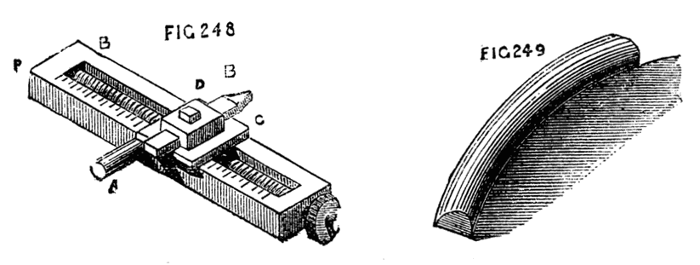
Figs. 248, 249.
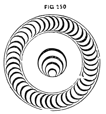
Fig. 250.
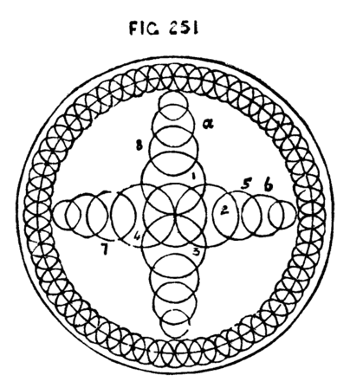
Fig. 251.
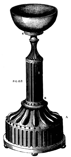
Fig. 252.
Take the finest sifted lampblack and make it into a paste with glue, about as thick in consistency as paint. After turning the ivory tolerably thin, paint this on the inside; let it dry, and repeat the process till sufficient is laid on to form a kind of hollow core, of strength sufficient to support the ivory against the action of the tool. The material may now be thinned and ornamented from the outside. When finished, soak a few minutes in warm water, and then agitate in cold; it will become quite clean as before.
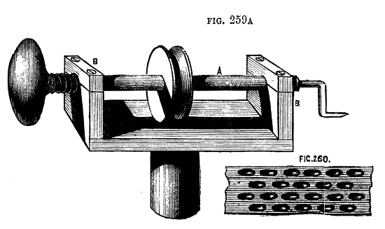
By altering the direction of the motion of the revolving cutter, the several cuts made by it will assume a different character, and the work will present a series of hollows scooped out, so to speak. The cutter, 253, being fixed in the tool holder of the top slide, will work vertically only, and produce patterns similar to Fig. 254, of the nature of basket work. This is exceedingly effective, and, as it may be cut so deeply as to penetrate the material of hollowed works, the latter may be lined with red or other bright coloured silk or velvet, and a variety of designs thus worked out. It is very necessary in using the vertical cutters to move the tool holder forward very gently, giving it at the same time great rapidity of revolution. Without this it will at once stick fast in the work. The character of the designs may, of course, be infinitely varied by using cutters of different sections, as in the case of work done with fixed tools with the aid of the eccentric chuck. The same cutters will, in fact, serve both purposes. Fig. 255 represents a tool similar to the last, but arranged to cut horizontally. With this, fluted work can be done: but it is evident that the cord from the overhead apparatus cannot here be directly applied, owing to the horizontal position of the driving pulley. Additional guide pulleys, therefore, become necessary, and, when these have to be arranged, the apparatus is generally modified, and the universal cutter is used, of which one form is shown in Fig. 256, and though it is not so good a pattern as that which is described in a later page, it is nevertheless suited for use with the old pattern of slide rest already delineated. With this the direction of the cuts may be varied at pleasure—they may be perpendicular, horizontal, or radial, and, when the templates before mentioned are added to the slide rest, an infinite variety of devices may be cut upon spherical and curved surfaces, so that the cutter thus modified is fully entitled to its title of "universal." The design, Fig. 258, is entirely the work of revolving cutters and drills used with a template of the required section. It is intended for a lady's workbox, opening with a hinge on the line, a, b, and containing in separate compartments the various articles required. It may be made entirely of ivory, lined with red or blue satin, and the flutes round the body may be cut through to allow the lining to appear. In the latter case, however, if the box is of ivory, black velvet may be used to enhance the contrast, and, as the glossy pile would be outwards, a second lining of any desired colour should be added with the best side inwards. The rings for the handles, as for all similar purposes, can be quickly made with the tool, Fig. 259. A hollow piece of ivory being taken, and turned smooth inside and out, one side of the tool is applied, as in the figure, so as to cut half through the work. It is then removed, and the opposite edge applied to the inside until the ring falls off completely finished. It is then cut through with a thin saw or knife, and inserted in the tailed ring or other projection intended to receive it. Handsome works in ivory should always be kept under glass shades. The universal cutter shown in Fig. 256 consists of a plate with chamfered edges to fit the tool receptacle of the slide rest, having near each end small poppets which support the round rod connecting the pulley bearing piece, A, with the part, E, which carries the tool, F, the latter being attached by a small slot and set screw to a cylinder revolving in E, and having at its upper end the driving wheel, C. At G is a circular piece or wheel racked on the edge, and turned by the tangent screw, G. The hinder poppet is rectangular, and has divisions marked upon it on each side of the angle numbered from the apex. The racked wheel may with advantage be similarly graduated. When the part E is vertical the cutter will be in a position to work horizontally, and the pulley support will be vertical. By turning the tangent screw, both the parts move together; but if desired the pulleys can move independently by unscrewing D and L. The angular poppet may be made semicircular if preferred, the degrees being numbered either way from 0" in the centre. When the tool holder is horizontal, or approaching that position, the nut, D, must be loosened, and the pulleys placed so that the cord will not slip off. They may be dispensed with if the apparatus is to be used only for vertical cuts (the holder, E, will be horizontal); but if a radial pattern is to be cut, in which the angle is to be constantly varied, the pulley piece must be used and the pulleys re-arranged at D, as required from time to time. There is a somewhat neat and serviceable little apparatus represented in Fig. 259A, to take the place of the slide rest and its revolving cutters, and although its powers are limited, much may be done with it. The spindle A, works through brasses in the poppets, B, B, and is put in motion by a cord from the overhead passing over the pulley in the centre. This spindle, which holds the crank-formed and other drills in a socket at one end, moves freely through the bearings endwise, and is kept back from the work by a spiral spring working against the end of the handle, C. This handle does not turn with the spindle, but is mounted like the handle of a carpenter's brace, or that of an Archimedean drill stock. The whole apparatus fits into the socket of the ordinary rest. A screw should have been shown in the drawing, passing through B towards the pulley, to regulate depth of cut.
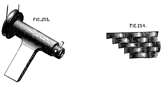
Figs. 253, 254.
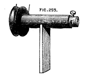
Fig. 255.
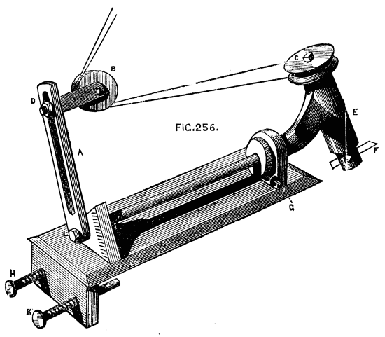
Fig. 256.
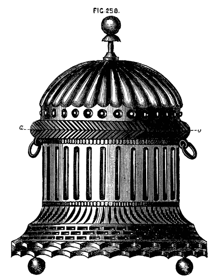
Fig. 258.
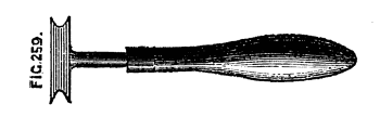
Fig. 259.
Figs. 259A, 260.
Once fixed by the screw of the latter in its intended position the tool is advanced to the work in a straight line by pressing the handle C, and is released from the cut as soon as this pressure is withdrawn. With different sizes of cranked, forked, or round ended drills, a good deal of ornamentation may be done with this simple tool, which is also useful for ordinary light drilling. By putting in the socket a round ended drill, and using the radial movement (turning the whole round in its socket in the arc of a circle), short flutes can be drilled out deep in the middle, forming basket work similar to Fig. 260, which is exceedingly pretty when carefully executed. There is little difficulty in making drills and cutters, as steel of all sizes in round and square bars may be had at the chief tool shops, especially at Fenn's, in Newgate-street. In making the revolving cutters, however, it is necessary to observe the position of the axial line, which must pass through the cutting edge. After the drill is roughly finished, therefore, it should be mounted in the tool holder with which it is to be used, and carefully tested upon a piece of unimportant work. If in revolving against the latter it leaves a part of the material untouched, the edge is not truly in the centre of rotation. The flat side of the drills are to be diametrical, and hence, as Holtzapffel remarks, these drills can only be sharpened on the end. The latter authority also says most of the drills embrace (in contour of edge) only about one-fourth of the circle, as when the drills are sharpened with one bevel they can only cut on the one side of the centre, and if the drills were made to embrace the half circle the chamfer of the edge on the second side would be in the wrong direction for cutting, and consequently it could only rub against the work and impede the action of the drill. All ornamental cutters and drills should be kept in a box with small separate divisions to fit the shanks, which are all of one size. The points can then be seen and the selection made of any required pattern.
Curiosities.
Many turners take special interest in the production of objects in the lathe, that at first sight appear impossible to be produced solely by its means. Inasmuch as such works manifest the skill and patience of the artificer, they will always meet with appreciation; and, although otherwise useless, they serve as elegant objects of vertu, and are well worthy a place among the rare ornaments of the drawing rooms. When first the Chinese balls, consisting of a set of hollow spheres one within the other, all exquisitely carved, were brought to England, it was believed they were made in hemispherical pieces, united round the equatorial line with some kind of cement, the joint being carefully concealed. I am not sure that they are made in a lathe in China; but, at all events, they are so made in England, and our home productions almost rival those of that strange yet clever nation. I say almost, because the carving in ivory done by the Chinese is in some respects unequalled, nor do I suppose that work requiring in many instances years of patient industry could be made to repay the cost of manufacture in England. No sooner were these curiosities in vogue here than all kinds of similar impossibilities were manufactured. Stars with from three to a dozen rays made their appearance, enclosed sometimes in similar sets of hollow spheres—the rays projecting beyond the limits of the outer shell—others were wondrously enclosed in cases with flat sides, cubes, pyramids, six, eight, twelve-sided hollow cases, all turned fairly in the lathe, were produced with similar contents, so that the apple in King George's dumpling became a very secondary wonder. The starry inmates were evidently too large for the houses; yet there they were—legs and arms, of course, sticking out through doors and windows, simply because there was no room for them inside. We will penetrate the mystery, commencing with a single hollow ball containing a star of six rays, the bases of the latter standing on a central cube.
In the first place a perfect sphere is required, and consequently the slide rest and template, or spherical rest, must come into requisition unless the turner can produce a ball by hand tools alone. Let this sphere, or rather its boundary line, be drawn on paper of full size with the compasses, Fig. 262, A, B, C, D. Draw the diameters A, D, C, B, at right angles to each other. This will give you five points, which on the sphere itself (on which these lines will have to be drawn, including also another, answering to A, B, C, D) are centres of six openings, here represented by the circles, through which the tools have to be introduced to hollow out the sphere and form the star. The points of the latter will be in the centres of these openings. Draw in addition the plan of the central cube, and one ray of the proposed star; next draw an inner circle, here dotted to mark the thickness of the outer envelope. The object of this drawing is to enable you to make a set of curved tools, one of which is shown black at E, and a set are marked on a plate of steel, from which they must be cut out. A close inspection of the figure will show that if ball, Fig. 262, were turning on the point A, A D being its axis of revolution, tools of the given section introduced at D would cut away the material round the point or ray, leaving the latter standing;[21] and this operation repeated at the five remaining openings would entirely free the central cube with its rays according to the proposed design. The tools have to be introduced in order, beginning with the smallest; and although the above remarks will make clear the principle, there are several points to be attended to in practice, and some few accessories are required which will now be explained. It is evident that for every different sized sphere fresh sets of tools will be requisite, which will also vary in pattern according to the intended form of the central base on which the rays stand; a cube or flat-sided solid requiring one tool at least, with a rectilineal edge; spherical or other solids demanding others whose ends are of different section. Hence, in all cases, full-sized plans of the proposed work must be drawn, and special tools designed therefrom.
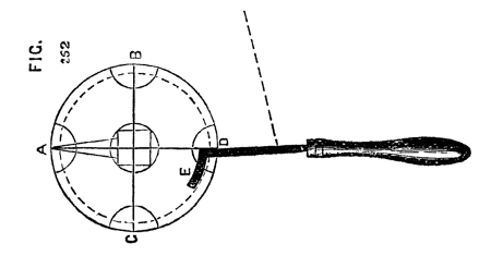
Fig. 262.
Figs. 269, 269B, 270.
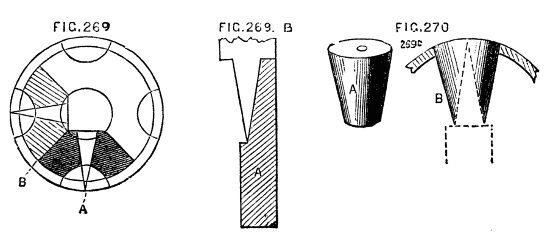
Fig. 269A is introduced to show more clearly the result of the application of the first set of tools, or rather of the first application of the set, as the latter are used throughout.
The blackened part will be entirely cut away in this operation, the shaded part meeting it will be removed when the tools are transferred to the adjacent opening, the cuts meeting those first made. Hence the tools need only reach from a to b, and can be more easily introduced than if the curved part were longer. Gauges, Fig. 269B, A, must likewise be made of thin brass or tin, that the progress of the work may be examined, and each opening in the sphere should likewise be measured with a gauge, or with compasses fixed to one width by an adjusting screw.
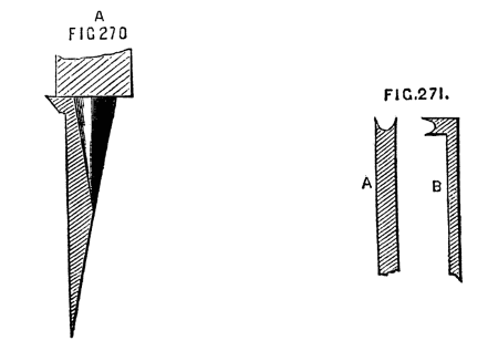
The proper chuck for this work is the capped ball chuck already described, by loosening the cap of which any one of the six openings may be brought under the action of the tool, these openings being, in fact, bored out simultaneously with the formation of the star. After the first point or ray of the star has been completed, the ball may be reversed and the opposite ray formed. These are now to be secured by plugs, which are to be turned conical, to fit the opening of the ball at one end, and of a length to rest upon the central cube at the other, being also bored out to fit over the rays, which they should embrace closely at top and bottom, even if not at the other points of its length. (Fig. 269C, A and B.) This is to be repeated as each ray is formed, so that the central star may be held in place until the work is finished, when the plugs are removed, and the star will be entirely detached. The above-named tools being straight on the right hand side of the shank will not form a finished conical point or ray. Hence it is recommended to file away that side, so that when flat upon the rest, the back of the tool may be an exact counterpart of a ray, Fig. 270, A. There is, however, no absolute necessity for this, as the star point can be first made blunt, with perpendicular sides, which can then be neatly finished by a separate tool made for the purpose, and kept up to a very keen edge. The first and smallest of the set of tools here shown, is the one with which the flat sides of the cube are formed, and it must be bevelled from underneath, so as to present a cutting edge on the end. The curved tools should cut on the end and both sides of the crook.
Figs. 270A, 271.
It is quite possible to make the above in mahogany, but a closer grained wood is much to be preferred, as the tools used—which are held flat upon the rest—are rather scraping than cutting, and mahogany, and fibrous woods in general, cannot be thus worked neatly. Boxwood is, in every respect, the best material to begin upon, ivory and blackwood being reserved until the eye and hand have become accustomed to such work. The whole operation requires great care, and is rather tedious, but the result ought to be a sufficient reward. The external surface may, of course, be ornamented with the usual apparatus, but the star should be left clear and sharp. The edges of the openings should have a light beading, cut with a bead tool, Fig. 271, A and B.
Grooving and Mortising Small Work.
Amongst the various purposes to which it is possible to apply the lathe, may be noticed the drilling out grooves and mortises, a method used in some of our Government arsenals, for cutting the recesses for the reception of the Venetian lath work in cabin doors. The same method is, of course, applicable to numberless similar cases, although designed for the special object named. The apparatus is shown complete in the drawing, Fig. 272, and the component parts in the succeeding diagrams. A is a kind of compound slide rest, or vertical straight line chuck, having a movement in a direction parallel with the lathe bed at F; while the circular plate being pinned through its centre to a slide, H, can be moved up and down by means of the handle G. This circular plate can be set in any position, and has a projecting shelf or rest to carry the work, which is steadied by guide pins, as will presently be explained. The part F, has a bed similar to that of an ordinary slide rest, which is clamped to the lathe bed by a bolt and nut, as usual. This carries likewise chamfered bars, between which slides the horizontal plate to which the vertical part of the apparatus is attached. This is first a plate with chamfered edges, Fig. 273 A, and a second similar but rather wider plate, Fig. 274 B, with guide bars, likewise chamfered, to slide upon A. From the front of B rises a stout pin, on which the circular plate, C, turns, which can be clamped by a central nut, or otherwise, as in an ordinary compound slide rest. This nut should not project above the general level of the plate. On the face of the latter is, as previously stated, a rest, or narrow metal shelf, D, and pins, e, f. The plate may be variously arranged in this respect by substituting any kind of holdfast or guide, according to the work desired to be done by its aid. The upper slide is depressed by a hand lever acting on a pin fixed in the sliding plate, Fig. 275; or, if preferred, by a similar lever, with a quadrant and chain, or rack movement. The horizontal slide is worked by means of a stirrup for the foot, with cord attached, acting on a bell-cranked lever, seen in the first figure. To cut the grooves in a bar, for Venetian blinds—as described—the lath to be drilled is attached to a flat strip of thin iron, drilled with holes, Fig. 276 A, as wide apart as the required distance between the grooves. It is then laid against the shelf, and the guide pins are made to enter the holes in the iron. The clamping nut of the round plate is loosened, until the bar is set to such an angle that the grooves to be cut will form vertical lines, Fig. 276. It is then clamped securely.
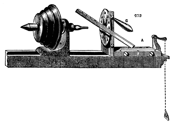
Fig. 272.
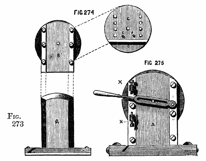
Figs. 273, 274, 275.
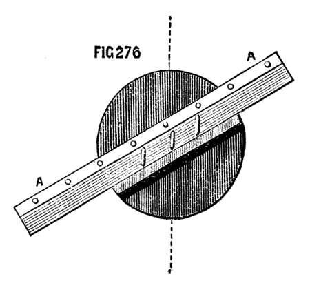
Fig. 276.
It is necessary to be able to adjust the piece to be cut, as regards its height, above the lathe bed. This is effected in part by the position of the movable shelf—fixed by pins—and partly by guide or set screws, which regulate the traverse of the slides. Suppose the bar adjusted as in Fig. 276, the groove to be cut being brought opposite to the drill. The set screws—two of which are seen at x, x, Fig. 275—acting on the handle, regulate the precise length of each groove. A similar stop, connected with the horizontal part of the machine, regulates the advance of the wood towards the drill, and thus the depth of the cut. Hence it is only necessary to set these carefully at starting—the pins on the guide plate insuring the proper width between the grooves—and the lathe being put in motion, any number of precisely similar grooves can be drilled with the utmost rapidity and neatness.
An inspection of the drawings will show what numberless purposes may be served by this simple apparatus, which may be modified in its details, while its principle of action is maintained. The drill should have a chisel and be kept to a keen edge. The lathe should be put in rapid motion, and if the required cut is to be deep, it should be cut at twice. The lower slide should return to its place by means of a spring when the foot is raised, the vertical slide being movable in both directions by means of the slotted part of the handle.
Note.—The above being taken from an apparatus for a steam lathe, the stirrup action maybe used, as the foot is at liberty. A foot lathe would require a slight modification. In Fig. 275, the depressing handle is shown as if the chamfered bars were fixed to the sole plate, and the plate A, were movable, as is sometimes the case. When made according to the above description, the handle would, of course, be pinned to the fixed vertical plate, A, to which also the stops would be attached, and the pin which passes through the slot of the handle, must project from one of the chamfered bars. Either plan may be followed, but the pattern described is calculated for a stronger apparatus; inasmuch as the vertical plate can be secured more firmly to the chamfered horizontal slide than the mere pair of guide bars—the two might, in fact, be made in one casting, if preferred.
Ornamental Turning.
The slide rest previously described, although applicable to the purposes of ornamental turning, has one disadvantage. It is necessary that the various pieces of apparatus to be used with it should have a foundation plate with chamfered edges to fit accurately between the guide bars. This is often inconvenient, and adds to the difficulty of making, and consequently to the cost of such pieces. In addition to this drawback, it may happen that one of these fittings by being more frequently used becomes more worn than another, so that the guide bars require constant re-adjustment, and their accuracy and parallelism become impaired. To obviate these and similar inconveniences the slide rest is now commonly made like Fig. 277, and a tool receptacle, Fig. 278, is fitted to slide between M, M, and is so arranged as to hold securely the universal cutters and other apparatus required for ornamentation or for plain turning. These are all made with a rectangular bar fitting the longitudinal channel in the middle of the receptacle, and are secured by the following simple contrivance. It will be seen by the drawing that the central channel is widened at A, A, and that a groove or saw-cut B runs along the inside from end to end. This groove is continued in a similar manner on the side next to the reader. Fig. 280 represents an ordinary tool holder, with a rectangular shank A, and clamping screw B, by which the tool c is secured. The part A is laid in the central channel, and a small piece of metal shaped like Fig. 279 is inserted in one of the open spaces, A, A of the receptacle and slid along with its lower flange in the saw-cut until clear of the enlarged part of the channel. It is thus retained, and the clamping screw which passes through its centre is brought to bear upon the piece to be fixed, which is thereby securely held in its required position. Two of these holdfasts are generally used at the same time. If the main bar of the tool holder is not quite thick enough to be clamped, then it is only necessary to lay a small plate below it. By the above simple means, the necessity for fitting each individual piece of apparatus to work upon the chamfered guides is done away. In order to ensure the position of the sole of the rest at right angles to the lathe bed a kind of saddle, A, Fig. 281, is used. This is of cast iron or brass, accurately planed on the upper surface, and has a projection fitting between the bearers of the lathe. The usual holding down-bolt passes through the hole in the centre, securing the saddle and the rest at the same time. The usual arrangement of a kind of double socket, the inner one rising at pleasure by being tapped into the outer, has already been described, and serves for accurate adjustment of the height of the rest. It is convenient, in addition, to have a stop or set screw under the bed of the rest, and a similar one on the top of the socket, so placed that when the frame is swung round it shall stop precisely at right angles to its former position. Thus, if the tool is first required to be used upon the side, and then upon the face of the object to be turned, these two positions are obtained at once, and can, if necessary, be alternated without any re-adjustment of the moving parts of the rest by the aid of the set square. The receptacle-holder is generally advanced by the hand lever, Fig. 279, one pin of which fits into the hole in the guide-bar as seen in the drawing, while the other falls into a short slot e, made in the upper surface of the receptacle, or of the piece of apparatus to be used in it. Of course, this arrangement may be reversed, one or both pins being fixed to the rest and its receptacle slide, and the holes made in the lever. Sometimes, however, a slower and more regular movement is required than it is possible to give in this way, and the lever is replaced by the leading screw C, D, Fig. 278, the head of which is removable, and can be replaced by a small winch handle. This screw is tapped into the lug cast upon the receptacle, and its point is of the form shown. The latter fits into a hole in the pillar A, 278, and is retained by a pin, which falls into the groove, D, Fig. 278, and prevents the screw from advancing or receding without carrying the sliding plate with it. The pin being removed, the screw will no longer act in this way, and the slide may be moved by the lever instead. The other screw, E, F, of fine pitch, serves to regulate the advance of the receptacle, and consequently the depth of cut of the tool—a round head with divisions on its edge is attached to one end, which abuts against the pillar B, Fig. 277, which latter has a mark on its top to act as an index. Thus the advance of the tool can be regulated to a great nicety, and successive predetermined and different depths may be reached and repeated at pleasure, as is sometimes necessary. C, C, Fig. 277, is one of a pair of stops which can be fixed by their screws at any two points of the bed of the slide rest. These serve to regulate the distance which the top slide and tool holder are intended to traverse, as in drilling a number of flutes of equal length, and many similar works. They are usually made of gun-metal, the screws of iron or steel, or of a metal called homogeneous, which may be described as between the two, and, being pleasant to work, is worthy of notice. It is absolutely necessary that the slide rest for ornamentation should be made with the greatest nicety. The slides must work equally smoothly from end to end of their traverse. The pitch of the screws must be not only fine, but even and regular, and the screw itself of precisely the same diameter from end to end, else it will work loosely through its nut in one place, and jamb in another. It is extremely pleasant to feel the exquisite smoothness and oiliness, for no other word will express it, of the movements of sliding parts in the workmanship of Munro or Holtzapffel, especially if compared with inferior work. Good amateur's work indeed is often far superior to that which is sometimes advertised, and perhaps a few hints may not be out of place here, relative to the construction of this necessary addition to the lathe.
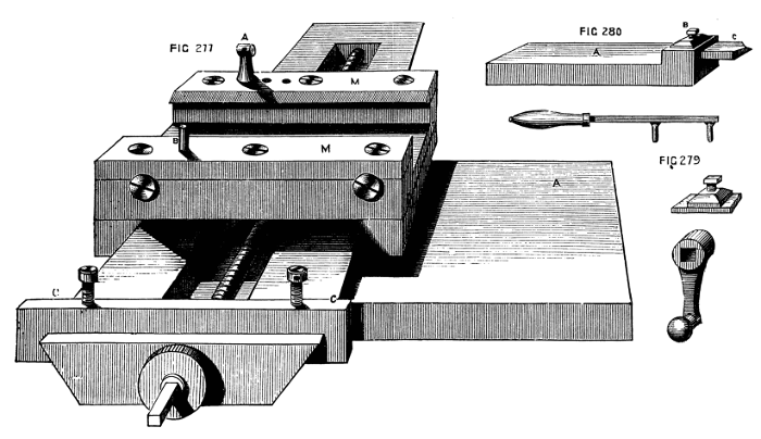
Figs. 277, 279, 280.
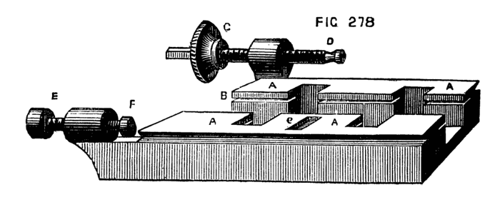
Fig. 278.
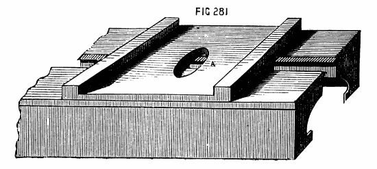
Fig. 281.
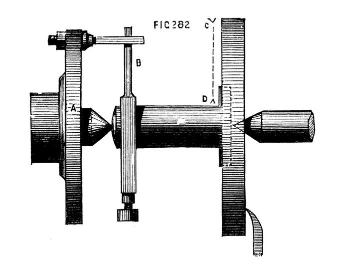
Fig. 282.
First of all, the frame of the rest must be accurately at right angles to the spindle, which fits into the socket. These should, therefore, be turned together, supposing the amateur not to have a planing machine. The whole may be mounted as Fig. 282, where A represents the carrier plate or chuck; B, the driver, the tail of which should be as long or nearly so as the frame from c to D; F is the side tool to be fixed in the slide rest for metal. The effect of this arrangement is to plane the face of the slide with transverse strokes instead of lengthwise. It may be afterwards finished and polished with oilstone powder on a flat slab of planed iron. When the face is finished, the whole must be reversed, the pin of the carrier plate will bear against the frame, which thus acts as a driver, and the spindle must be turned. In this way accuracy is ensured if the slide rest used is carefully set. The chamfered sides of the slides are difficult to work with the file, but may be so done with care, and with a template of the desired bevel as a guide. The great secret is to take plenty of time, not to press too much upon the file nor to move it too quickly over the surface; fine even strokes, especially towards the finish, must be given, and a final polish with oilstone powder and oil used on a piece of a stick. In turning the screw a back stay must be fixed opposite to the tool in the slide rest to insure the contact of the cutting edge without bending the work.
Presuming that the screw will be cut with stock and dies, it may be stated as a caution that the latter must not be tightened except at the commencement of cutting the thread deeper. The return of the tool by a backward motion (or unscrewing), should not be used as a cutting action, and therefore, should be carried on with the dies in the same position which they had during their descent.
At the beginning, therefore, of each downward movement the dies must be tightened and oiled, and they must not again be touched till the bottom of the screw has been reached, and the upward movement also has been completed, so that they have arrived again at the starting point. If tightened at any other time the screw will be either conical or of a wavy section, either of which forms would be fatal to its use. The castings for such a rest should be of malleable iron, if possible, as being much more easy to work; the guide bars may be of gun metal, as also the chamfered bars, which work on the main frame. This will give a more finished appearance, and will on the whole be more durable and satisfactory.
The Eccentric Cutter Frame.
One of the most useful tools for ornamentation, especially of plain surfaces, such as the top of a box cover, is the eccentric cutter, Fig. 283. The shank, A, lies in the receptacle holder of the slide rest, and is drilled throughout to receive a steel spindle, carrying at one end a double pulley, B, to receive the cord from the overhead motion, and at the other frame, E, with its leading screw, of which the movable milled and graduated head is seen at H. This frame has one surface, level with the centre of the main spindle, which is cut away as shown, and, consequently, as the point of the tool is on its flat side, which latter rests upon the frame (the bevel being below), this point can, by the tangent screw, be brought into a line with the centre of the main spindle, so that when the cord from the overhead is passed round B, the spindle revolves with great rapidity, and the point of the tool, K, in the position described, makes a simple dot. By turning round the milled screw head, H, either by the thumb and finger or by a small winch handle, fitted on the square part beyond the head of the screw, the tool holder, D (which is in one piece with the nut of the leading screw), is made to traverse the frame, and the tool will cut a circle small or large according to the eccentricity thus given to it. In Fig. 285 D, is the tool holder on the front of the frame; C, the end of the spindle; L, a bell-shaped washer, which is acted on by the small square-headed screw, drawing D towards the frame and clamping the tool. The whole is in the figure of full size. The tool holder is in one piece with the nut, through which passes the leading screw, and which is continued as a screw for the action of the bell-shaped washer and tightening nut; hence it is necessary to allow a degree of play between the nut and leading screw, to prevent bending the latter when clamping the tool. This is effected by filing off the threads in the nut at the top and bottom, to render the whole slightly oval. The remaining threads suffice for the action of the leading screw: a very slight degree of play in the required direction will be found sufficient. The powers of the eccentric cutter frame will be found sufficiently extensive to make it a most serviceable, perhaps necessary, piece of lathe apparatus. If it cannot be said absolutely to supply the place of the eccentric chuck, it has nevertheless the advantage of great lightness of construction, lowness of cost, and ease of manipulation. The weight of the eccentric chuck, whether single or double, as of all chucks in which sliding plates are used, is a sad drawback to their value—a drawback unfortunately beyond remedy, and specially felt when the slides are drawn out to a great degree of eccentricity. Combined together, these two form a compound eccentric chuck, and in this way are capable of nearly everything in the way of eccentric ornamentation. Where the chuck is not to be had, it is by all means advisable to procure the cutting frame, for which the writer confesses a great partiality. It appears, indeed, to him a far more rational proceeding, as it is also now of extensive application, to act upon fixed work by revolving or moving tools, instead of proceeding in the contrary way; and all these little tools used with the overhead apparatus are so lightly and elegantly constructed, and so well adapted for the parts they have to perform, that the originator of them (native talent devised them), deserves to be well and lastingly remembered; instead of which it is doubtful whether his name is even known. (Sic transit is a quotation too stale for this work.)
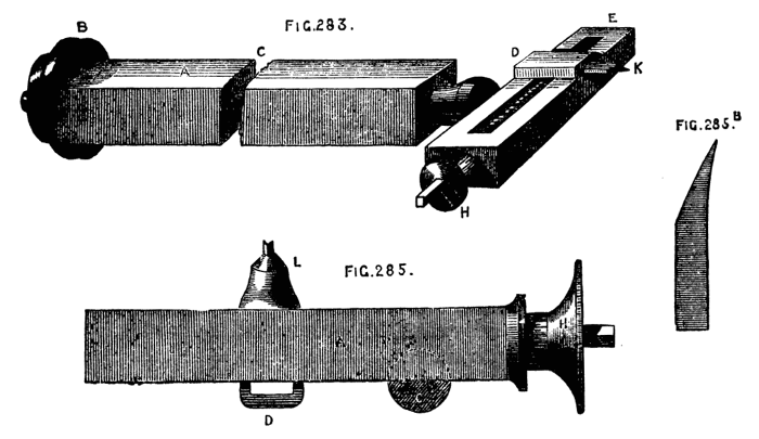
Figs. 283, 285, 285B.
To cut circles deeper in one part than another—the shell pattern, for instance—with this tool, it is not necessary to alter the level of the sole of the rest, as it is when the eccentric chuck is used with a fixed tool, as it suffices to set the rest itself at an angle, by moving it round in the socket, so that the revolving tool should touch the face of the work sooner at one point than at an opposite one. In the same way the work may be considerably undercut on one side of the circles, by giving the angular set to the rest, and placing a tool in the holder, with a point of the form shown at 285 B. There is nothing prettier than this undercut work when well and sharply done, for which purpose the tool should not only be rendered keen on the hone, but burnished and polished on the brass and iron slabs already described. The following remarks on the work of this cutter frame on flat surfaces only, will be useful to the reader in designing and working out the various combinations of circles, intersecting or otherwise, which it is calculated to produce. On a surface represented by 286 A, the line of circles, a, a, is on a diameter, and, supposing them to be described by the eccentric cutter (or by a simple double-pointed drill), their centres are obtained by means of the leading screw of the slide rest, moved the requisite number of turns between each cut, while the work is retained in a fixed position on the mandrel. But if the line of circles is on such a line as b b, above or below the centre, and consequently not on a diameter, it is plain that no movement of the slide rest or cutter, or both, can avail to place them in position, except with great difficulty and tedious working with the division plate of the lathe and the screw of the slide rest. Hence the eccentric chuck must be brought into play, and being fixed with its slide in a vertical position, the screw is turned and the work is lowered thereby until the line b, b, is on a level with the point of the tool. The eccentric cutter or double drill will then suffice to work the row of circles. When the centres of the circles are themselves on parts of the circumferences of other circles, the division plate of the lathe or of the eccentric chuck will be called into requisition, according as these circles are concentric with the mandrel or otherwise. In Fig. 286B, the curved lines are parts of circles of equal size with that representing the surface of the work, and their centres lie on one and the same diameter, viz., at opposite extremities of the line, a, b. Being thus eccentric to the work, the division plate of the chuck is used to arrange the intersecting circles of the pattern—its slide having been first drawn down, until the centre of the arc to be worked with circles is brought opposite to the tool. The work will be in position when, on turning the mandrel slowly, the cutting point of the tool passes across its centre. The division of the original circle is in this instance into four parts, two of which are thirds, and two sixths of its circumference. The arcs of circles are also lines equal to thirds of the circumference of the work. It is well to remember this division of a circle by other equal circles described round it from points on its circumference, these circles passing through the centre. The original circle will in this way be divided, as shown at C, into six equal parts. To produce it with the aid of the eccentric cutter is easy. Set the tool of the cutter first to the centre of the work, so that on revolving it will make a simple dot. This should always be done, whatever pattern is subsequently to be cut. Fix the index of the division plate of the lathe at 360. Move the screw of the slide rest until the point of the cutter, on being advanced, rests on the circumference of the circle previously cut upon the work, or on the circumference of the work itself, if the divisions are to reach the edge. Screw back the tool (not the rest) until its point reaches the centre of the work and cause it to revolve so as to cut one arc. Move the lathe pulley forward to 60° and cut a second arc, and so on, advancing 60° each time, and the figure will be cut. This division of the circle will form the groundwork of many handsome patterns. When the arcs thus formed are intended merely to be the lines of centres, and not themselves to form integral parts of the pattern, they should, nevertheless, be marked with a pencil in the tool holder, if possible, as there will be less liability to error in working the proposed pattern. In the present advanced stage of the art of turning, mere surface work done by the eccentric cutter is rather apt to be despised, owing to the extended powers of Ibbetson's or Plant's geometric chuck; but, valuable as the two latter are, they are necessarily so costly that few can obtain them, whereas the little cutter frame is comparatively cheap, and it is really capable of very exquisite work in skilful hands.
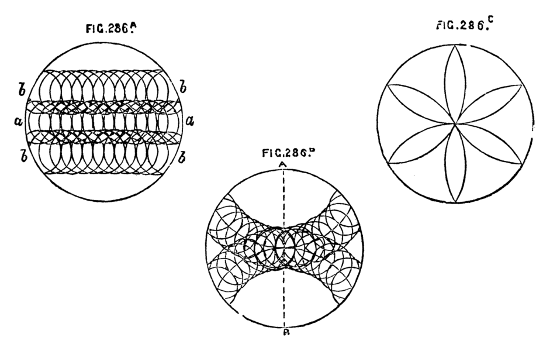
Fig. 286A, B, C.
Segment Engine. Fig. 287.
In very many cases of ornamentation it is required that the mandrel, instead of making an entire revolution, should stop at a given point in both directions, so that, for instance, the turner should be able to move it 60, 80, or 100 divisions to and fro, with the certainty of its not advancing beyond that distance. This is effected by the racked and divided brass wheel B, fixed on the mandrel against the small end of the pulley. This wheel is sufficiently thick to allow of racking part of its edge to be acted on when necessary by the tangent screw, and leaving the other part for divisions, which are generally seventy-two in number, and marked in figures at every sixth division. On the other side of the plate are a number of holes drilled through its whole thickness to receive stop pins, Fig. 289, P, which are sawn through as shown, that they may spring, and fit the holes tightly. There are seventy-two holes corresponding with the divisions. These pins are about 3/16ths of an inch diameter, generally with flattened heads, and a hole through them to receive a pin to aid in removing them. The holes are sometimes made in the edge, instead of the side of the segment plate, but the latter is the best position. At Fig. 288, T, is seen the interior part of the poppet, with a piece of brass let in, and fixed securely, in which are inserted two screws, against which the segment stops abut, and prevents further rotation of the pulley. Side by side with this latter piece is placed the frame which carries the tangent screw. It is shown at Fig. 289. This frame is not fixed to the base of the poppet, but pivotted at e, between two short standards screwed into the poppet for that purpose. When not in use, the whole frame, therefore, drops down towards the front, but it can be raised by the small cam, K, Fig. 289, so as to gear with the worm wheel. In many cases the latter is not used, but the pulley turned by hand. The screw, however, gives a steadier and more easily regulated movement, essential in delicate operations, and sometimes convenient, even when the stops do not require to be inserted. The use of the cam, acting on the frame which carries the tangent screw, is now generally followed in the eccentric and oval chucks, and also in the dome chuck. It enables the workman, by throwing out of gear this part, to turn the worm wheel with the fingers, to set it at the required number on the division plate, a slow process when effected by the screw.
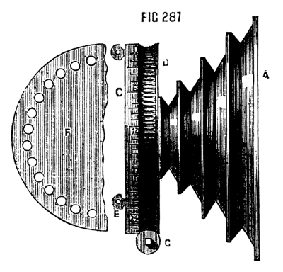
Fig. 287.
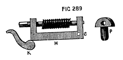
Fig. 289.
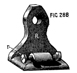
Fig. 288.
Holtzapffel's Rose Cutter Frame.
Among the newer devices for ornamental turning, must be mentioned the rose cutter frame of Holtzapffel and Co., an ingenious adaptation of the principle of the rose engine, without the drawback of cumbersomeness and costliness. It works like the ordinary eccentric and other cutters by a cord from overhead motion. The apparatus is represented in Fig. 290, and its various parts in Fig. 291, &c.
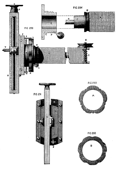
Figs. 290, 291, 293, 294.
In the first of these figures, A is the shank, fitting the receptacle of the slide rest, and drilled to receive a hardened spindle, at one end of which is a worm wheel, turned by tangent screw B C, and shown again at A, B, C, Fig. 292. By this are turned the parts beyond K, namely, the frame D, carrying the tool, as in the eccentric cutter, adjacent parts S, representing chamfered bar, P, back plate, and O, which is a round piece in one casting, with the back plate, and having a hole through it for the coiled spring seen between O and N. All these are secured to the spindle, and turn together as one piece with it. Fig. 291 is a front view of these parts. H is the back plate of brass, with steel chamfered bars on its face, E, E, as in the eccentric chuck. Between these slides the plate, D, D, to the face of which is attached the long steel frame, carrying the tool holder. Close to the letter H, it will be noticed that a slot is cut in the back plate, through which projects a hard steel pin, screwed into the back of the sliding plate. This is seen at O, Fig. 290, and is attached to one end of a coiled spring, the opposite end of which is secured to a pin fixed in the back plate of this part. The pin O, is thus kept in contact with the edge of the rosette or pattern plate, K, and, as the whole turns with the spindle while the rosette is fixed, the pin, or rubber, is compelled to follow the undulations of the pattern, the motion being, of course, communicated to the tool. An inspection of Fig. 294 will show the arrangement of the parts on which the rosettes are fixed, and which is capable of turning, but does not, unless the tangent screw and wheel, H, are brought into requisition, as will be presently explained. The end of the main shank of the instrument is round, as seen at C, the worm wheel B being screwed fast, by four small screws, to the end of the square part of the shank. Upon this rounded end fits what may be called the sleeve E, to which is fixed the tangent screw, and on which also are placed the rosettes. The latter have a large central hole, Fig. 293, A and B, and fitting closely beyond the screw F, F, of the sleeve, and, being prohibited from turning upon it by a small key or feather, are secured by a screwed ring or ferrule seen at L, Fig. 296, the edge of which is milled. At F, Fig. 291, is seen a short stop, or set screw, the head of which is divided into ten degrees. By this, the rubber is prevented from penetrating to the bottom of the undulations on the edge of the rosette, and, if it is allowed only just to touch the summits of them, the tool will cut a circle. Thus, as the screw stop can be accurately set, one rosette will produce at pleasure graduated waved lines, the waves growing less and less undulated as the centre (or circumference) of the work is approached, giving a most delicate and chaste pattern, and chased it certainly is.
Another variation of the pattern producible from any rosette results from the frame of the tool holder being extended beyond the axis of the spindle in both directions. When the tool is on that side of the axis nearest to the rubber pin, the undulations of the rosettes will be so followed as to produce their exact counterpart on the work. When the tool-holder is on the other side of the axis, the undulations become reversed, the raised parts of the rosettes producing hollows and vice versa. It may here be mentioned that in the case of the rose cutter, eccentric, and universal cutter, and similar apparatus, the screw heads carry ten chief divisions and ten smaller divisions. The screws are cut with ten threads to the inch, so that one turn advances the slide, or the tool, or wheel as the case may be, one-tenth of an inch. One large division, therefore, produces a movement equal to one-hundredth, and one small division one two-hundredth of an inch. If the screw is small it is generally cut with a double thread equal to one-twentieth of an inch. It is evident that in addition to the movements of the various parts of the rose cutter, the turner also has in his power those of the slide rest, and of the division plate on the lathe pulley, by one or both of which further complications become possible. Six modifications of pattern produced from one rosette alone are shown in Holtzapffel and Co.'s catalogue, and these may be further multiplied according to the taste and skill of the operator.
It is not possible to apply rapid movement to this rose cutter, else the rubber would probably miss touching the rosette in places; hence the tangent or worm wheel is used to give motion to the central spindle. An end view of this is given in Fig. 292. The object of the other tangent screw is, to move the sleeve and therewith the rosette at pleasure, so that the higher parts of the undulations in the second cut may, if desired, be arranged to meet the lower parts of the same in the first cut or to fall intermediately. The effect of the gradual shifting of the rosettes in this way is perfectly marvellous, and the writer much regrets that he is unable to supply specimen plates, as he is not in possession of the rose cutter. In the end of Holtzapffel's latest edition of his catalogue are several such specimens, but without any drawing or description of the instrument, the cost of which is moreover omitted.
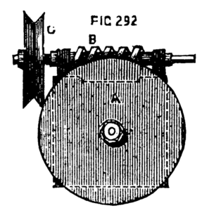
Fig. 292.
The centres of circles cut by this eccentric tool will be always regulated in regard to position by the slide rest, because these centres are, as explained, always in a line with the centre of the spindle. Hence, to place a circle in any desired position, it is only necessary to determine its centre, and, after drawing back the tool by means of the screw till its centre runs truly as a mere drill, turn the screw of the slide rest until the point touches the required spot.
Universal Cutter Frame.
This is represented in Fig. 284, in its latest improved form. It consists of a shank, A, which fits the tool receptacle, and is bored throughout its length for the reception of a central steel spindle, to which is securely attached at one end the worm wheel, G, acting as a dividing plate, and at the other the crank-formed frame, B, C, with its small poppets, D, D. These are sawn lengthwise, and thus spring upon the centre screws, which pass through them and carry the revolving cutter spindle, K, L, M, in the centre of which is a slot to receive the tool, the latter being clamped by the tightening screw, L. There are certain points to be attended to in the construction of this instrument, which must on no account be neglected. In the first place, the screws which pass through the poppets must lie in the line which would bisect at right angles that of the main spindle in the same plane. A line, in fact (as dotted), passing from screw to screw will pass across the centre of the end of the spindle. In the next place, when the tool-holder, with its pulleys, is in place between D, D, this line must be even with the top line of the central mortise, H, for the point of the tool is level with its upper surface, it being bevelled below; and it is essential that this point be capable of being so placed as to form a continuation of the centre of the main spindle. At E, E, are shown two of four thin pulleys. The two front ones are removed to show the poppets. They should not be made thicker than necessary, in order to avoid their interfering with the action of the tool. Either pair will be used with either pulley, K, K, according as the right or left side of the instrument is the highest, for, as will be explained, the cutter frame is used at all angles between the horizontal and the vertical lines, the cuts being consequently inclined in either direction, left, or right, at pleasure. The centre screws and points of the tool spindle must be carefully hardened. Before commencing to use this cutter, it is necessary to test the centrality of the point of the tool. Place the latter in its holder. Let the part C of the instrument be turned till vertical; cause the tool to revolve and to cut a light line or scratch on the face of the work. By means of the tangent screw cause C to become vertical in the opposite direction, so as to bring the other pulley upwards, and with the small screws in the poppets set the revolving tool holder, till the tool falls exactly on the line first made. It is, of course, understood that the line in question passed through the centre of the work. If in both positions of the tool the central point is passed through, the cutter tool is correctly placed. The poppet screws are for this purpose specially, though sometimes used to place the cutter purposely above or below the centre of the work. Compared with the old form previously given, this pattern of universal cutter is very superior.