THE LATHE AND ITS USES. (continued 3)
Reading edition
Of recent inventions in the matter of drills, the most important is the Morse American twist drills sold, in sets, at 30s. on a neat stand with a self-centering chuck, complete. The form is that of a cylinder with spiral grooves cut round it of extended pitch. The cutting edge is as difficult to draw as it is to describe, and must be seen to be understood. It is chiefly formed by the meeting of the spiral grooves and the solid end, the latter forming a blunt angular point rendered cutting by the edge of the grooves. They should have a place in every workshop.
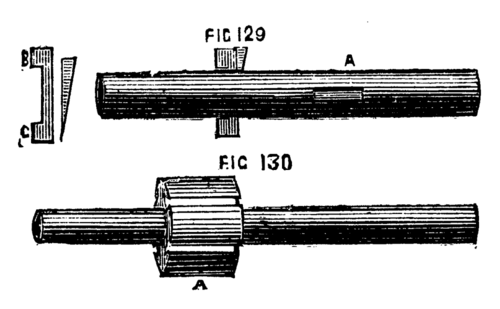
The next tool to be described is also much used, especially in agricultural implement manufactories, for boring out the brasses, or bearings. It is called a rose bit, or grinder, and is shown in Fig. 128 A and B. In this case also a recess is cut in the work as a guide, and as the tool fills up the whole interior as it proceeds, no change of position can occur. The rose bit is used as shown in 125. A bit of this pattern is very useful for brass work of all kinds, such as the cylinders of small engines, bosses of wheels, bearings and collars, and one of these tools of the exact size for hollowing out the sockets of brass chucks, previously to their being tapped, will be found serviceable. The third kind of boring tool is made with movable cutters, which can be removed at pleasure, to be sharpened or replaced by more convenient ones. The simplest consists of a cutter bar, A, Fig. 129, with a slot in it to hold the tool, which is fixed by driving a wedge at the back of it. The tool here shown has two cutting edges, b and c which should be shaped according to the principles already enunciated respecting hand tools for iron and brass. The cutter bar is usually fixed between the lathe centres, and turned by a driver chuck and carrier, while the cylinder to be bored is clamped to the slide rest, and thereby advanced against the cutting edge. This form is chiefly used upon work that has been cast hollow, or drilled.
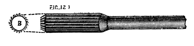
Fig. 128.
Figs. 129, 130.
Fig. 130 is another form of boring tool for large and heavy work. A boss, A, is fixed to the cutter bar, having a series of dovetailed grooves, or slots, on its surface, in which cutters are fixed by wedges. In this and every similar form, it is expedient always to complete the circle, or, at any rate, two-thirds or three-quarters of it, by driving in blocks of wood in the slots not occupied by the cutters. This preserves the concentricity of the tool. One edge of these movable cutters should be radial to the centre of the bar, or boss, the other rather less than a right angle, which will ensure a good cutting edge. The best lubricant is oil for the first cut, and soap and water, or pure water, for the finishing cut. The surface will thus be left bright. It is not well to finish with emery any collar in which an axle is to work (as the collar in which the mandrel of the lathe runs). This substance imbeds itself in the pores of the metal, and by forming a grinding surface, considerably increases the friction and wear and tear of the parts.[8] Although boring and drilling are capable of being done in the lathe, a far superior plan is to employ an upright boring apparatus, as is now generally used in making steam cylinders. The work is not then suspended between two points, or carried on the slide rest, but takes up a firm bearing on a fixed support, and the boring tool descends by a pressure screw, or self-adjusting contrivance, as the work proceeds.
We have spoken of the slow motion as necessary for turning metal work. This is represented in Fig. 131 A B C D. The first is a plan seen from above. The poppet is cast double like F, so as to afford a bearing for the mandrel, and a second for the back spindle seen at A. This back spindle, it will be observed, passes through its two collars or bearings, and can slide freely in them from side to side. This can, however, be prevented by dropping a pin through a hole in the top of the poppet, which falls into a semicircular groove in the spindle. The pulley is securely attached to a small cog wheel, and can be firmly united to a larger one, as seen at A2, and separately at C and D. This pulley and small cog wheel run loosely on the mandrel, and do not revolve with it until clamped to the wheel, C, which is itself keyed to the mandrel. Suppose them to be thus free to revolve, and the wheels in position shown in the plan, A. On putting the fly wheel in motion, the pulley will revolve on the mandrel, carrying with it the small cog wheel, which in turn will act on the large wheel on the back spindle. The small cog wheel on the latter will thus put in motion the large one geared with it, the which being keyed to the mandrel, will put the latter in motion. There are many ways of clamping the pulley to the large cog wheel, perhaps the following is as good as any. It must be so clamped for wood turning when the back spindle is to be slipped on one side out of gear.
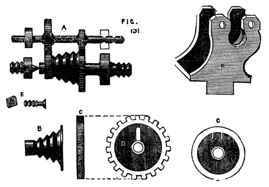
Fig. 131.
In the face of the pulley, which is concave, is a piece of brass flush with the rim, and which forms a dovetailed groove, into which the head of a clamping screw, E, fits. This screw projects through a slot in the wheel D. When it is required to fix the pulley, this screw is slid up towards the rim till the head rests in the dovetailed projection, and it is clamped in that position by a nut. When it is desired to put the back action into gear, this nut is loosened, the screw-bolt dropped towards the axle (thus freeing the head from the dovetail), and again fixed by the nut. The wheel and pulley are thus independent of each other, the back spindle is slipped sideways into gear, and held by the pin, and the slow motion will be obtained.
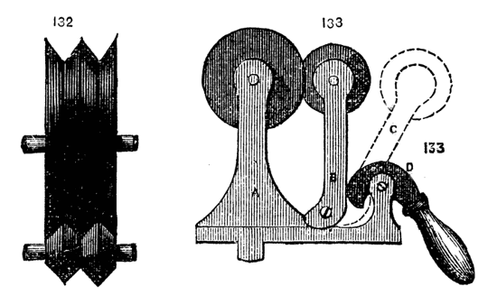
There is one fault in the arrangement of the back geared lathe that with amateurs in a private house is especially disagreeable, and it is questionable whether in large machinery establishments it might not with great advantage be corrected. In the action of toothed wheels, nuts and screws, and similar gearing, there occurs what is called back lash. If, for instance, the tool holder of a slide rest is advanced, and then the action is to be reversed, the movement of the nut and tool holder does not commence simultaneously with the movement of the screw. This is due to the play, or necessary looseness of the working parts, the pressure coming on one side of the thread when the screw is turned in one direction, and on the contrary side when the motion is reversed. In toothed wheels a similar defect exists, and gives rise to that disagreeable and ceaseless noise which assails the ear on entering a building where machinery is in motion. This may be avoided by the use of frictional gearing, a simple but excellent mechanical contrivance which deserves far more extensive notice than it has yet received. It is the invention of a Mr. Robertson, and is patented. A lathe fitted with it would be almost noiseless, and would work with a delicious smoothness, very conducive to the comfort of the workman. This gearing, represented in Fig. 132, is merely the substitution of V shaped or semicircular grooves for cogs, the former running round the periphery of the wheel like the grooves in an ordinary lathe pulley. In this method of gearing, it would be necessary to move the back spindle to-and-fro, the usual horizontal movement not being possible. This is easily effected by a screw or a cam, either of which might be made to act on the frame which carries the back spindle, and which may then work on a centre, as Fig. 133, where A is the poppet, B, the support of the spindle, D, a cam; when the handle of the latter is raised, the standard, B, is allowed to fall back out of gear into the position shown by the dotted line, C. A screw movement would have the advantage of enabling the workman to regulate with greater precision the pressure of the friction pulleys against each other. The drawing shows the grooves of these pulleys larger and deeper than usually made. They are generally rather shallow and numerous, and it is astonishing with what firm hold they grip each other without that violent pressure which it might be imagined would be necessary to prevent slipping when in use.
Figs. 132, 133.
The ordinary slide rest for hand lathes is made as follows:—That for ornamental turning will have a separate notice. Fig. 134, shows the slide rest viewed from above, and it is evident if the tool is clamped to the holder F on the top plate, it can be advanced from end to end of the top slide B, and also (with the upper frame itself) along the lower frame A, A, these movements being at right angles the one to the other. For parallel work this is sufficient. In this compound rest a third motion is arranged for turning cones or taper plugs like those of stop cocks, taps for screw plates and such like articles. For this purpose the upper frame is cast like Fig. 135, with a flat surface, but with two ribs underneath, uniting the frame to a circular plate with two concentric slots in it. This plate revolves on the plate G G, turning on a central pin, and it can be clamped by the two screws which pass through the slots into the plate in any desired position; once clamped at the required angle a piece of metal can be bored with a conical hole and a plug turned to fit it without possibility of failure. The details of construction allow of considerable variety, and different makers keep to their respective patterns; the main desideratum is strength and solidity, combined with accurate adjustment of the moving parts. The V's, underneath the frames, and the edges of the latter, must fit, so as not to be tighter in one place than another, and the upper and lower frames must cross each other accurately at right angles. It is likewise essential that the tool traverse the work in a perfectly horizontal line. Every part must, therefore, be accurately made by means of the lathe and planing machine, and the whole carefully put together. Notwithstanding the above desiderata, a slide rest is not necessarily beyond the skill of the amateur. We have, indeed, seen one thus made quite equal to the work of a professed mechanic, though the file and scraper had to take the place of the planing machine. The rough castings can be bought for about half-a-crown, suitable for a five-inch centre lathe, and it would be much better to try and fit up a set of these castings than to attempt such a substitute as a wooden slide rest. The latter has nevertheless been made, and we remember seeing one of mahogany edged with brass, the work of a cabinet maker, which did good service in turning and ornamenting wood.[9] This, however, was upwards of twenty years ago, since which time the facilities for obtaining slide rests of metal, properly constructed, have materially increased. As the dovetailed edges of the slides wear away by use, it is necessary to provide means for tightening up the V-pieces. This is shown in Fig. 136. The holes in the V-pieces through which the top screws pass are not round, but oval, so as to admit of lateral movement.
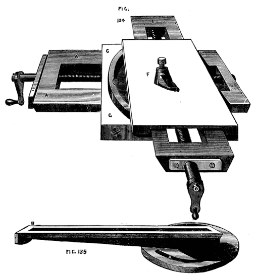
Figs. 134, 135.
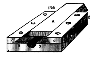
Fig. 136.
Two large headed screws, E, E, are tapped into the place on which the V-pieces rest, and when these are screwed up, their heads (which are sunk for the purpose in two recesses in the lower plate) press against the V-pieces, driving them closer to the dovetailed slide. When thus adjusted the top screws are made use of to fix the strips c, c. By this method the slides can be adjusted to work with the utmost ease and accuracy, without shake or side play. The edge of the circular plate and the heads of the leading screws are very frequently marked in graduated divisions, so that the advance of the tool or the angle to be made with the work by the tool can be accurately measured and preserved. There should at any rate be a mark on the circular plate to show when the rest is set for parallel work. There are several patterns of tool holder, of which the forms shewn are convenient for light work. The one shown in 138 & 139 on the rest is somewhat different. The plate F, Fig. 134, is cast with a boss and socket, like that of an ordinary rest. In this socket the tool holder fits, and can be not only turned round so as to set the tool at any angle, but also slightly adjusted in height, which is a great advantage. The tool is clamped by a single screw as shown in the sketch. The drawback to this form, and that on the rest, is this single screw, which will indeed hold the tool when the work is easy, but will not always retain it with sufficient firmness when the work is rough, or of tolerable size. In large workshops one usually meets with the holder represented in Fig. 140. A plate, A, with central block B, and slide C, are in one casting. Through A pass eight screws. The tool lies on either side of the central square block and is clamped with three screws, it has thus a fair bearing on two sides, and the screws form a third above, so that accidental shifting of the tool during the progress of the work is hardly possible. The tool holder of Professor Willis, which is described in the Appendix, is perhaps the best of all at present in use. It holds the tool firmly at any desired angle.
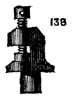
Fig. 138.
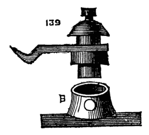
Fig. 139.
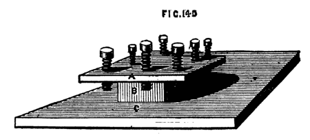
Fig. 140.
It is quite possible that the novice who has seen mere boys working with slide rests at manufactories will be disappointed at his own first attempts to use this piece of machinery. All the difficulty lies in the shape and set of the tool. When turning metal with hand-tools it is easy to feel one's way. If the cut is not satisfactory, the hand at once modifies the angle of the tool, and regulates its direction to a nicety, but the slide rest cannot thus adapt itself to its work. It must be set with its slides in position, and the tool once fixed must pursue its own course. Hence it requires a very accurate knowledge of the nature of cutting tools, such as we have given in the Appendix to this work. If the tool is well placed upon the axis of the work for iron, a little below it for brass—it will cut cleanly and easily, without rubbing or jarring, both of which are proofs of either a wrong angle of edge, or a wrong form of tool. The work should proceed with as much apparent ease as if the metal were an apple, and the shaving should curl off like its peel. Moreover, this case is not merely apparent, it is perfectly easy to cut iron, and the strain on the tool, whether held by the hand or by slide rest, is comparatively slight, if the tool is properly made and held. Fig. 141 is quite the best form of tool for surfacing cylinders with the slide rest. It is to be so placed that both edges are made to cut near the point; hence the crank should slightly curve away to the left. It is not possible to cut metal quickly, be content with fine clean shavings curling off freely. You will soon see whether you can take a deeper cut with safety. The tool here sketched is not at all likely to dig in and hitch in the work; if it is not properly placed it will spring and jump, or its side will rub against it, and no cut will be made. To describe the exact position is very difficult, but the principle once grasped, little difficulty should be experienced in making and setting to work any tool, whether for inside or outside work. The rule of thumb was all well enough in olden days and in the infancy of the art of metal working, but it is time to discard it; to master and man it is equally advantageous to do so. Indeed, in some of our leading firms, the old system of follow-my-leader, when the leader was as ignorant of his work as the follower, is waning, and the "how" is now, as it ought to be, coupled with the "reason why." One of the best papers ever written on this subject is to be found in Weale's series, "Mechanism and Construction of Machines," by T. Baker, and "Tools and Machines," by J. Nasmyth, 2s. 6d. The latter part is that specially referred to, and is well worth the whole price of the work. The remarks, however, of that eminent mechanic are embodied in the paper in the Appendix, and therefore, after the reader has studied the latter, he should make trial for himself of the principles laid down. Expend a quarter or a half an hour experimenting thus, with keen and obtuse tools, held at divers angles, and you will see and understand what is meant by setting a slide rest, or hand tool to cut metal as it ought to do.
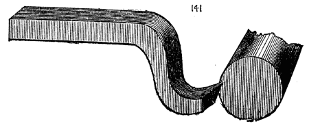
Fig. 141.
Fig. 141 is too much cranked; half the length of the hanging part would amply suffice.
Supposing the tool fixed in the tool holder in the position indicated, and just overlapping the circumference at one end (the right). Take hold of the handles, one in each hand, and with that which advances the tool from end to end of the bar try very carefully whether the tool will cut cleanly by making a turn or two while the lathe is in slow motion. If the tool bites too deeply, turn the other handle and ease it. If you still find the tool sticking into or scraping the work, instead of bringing off a fine shaving, look well to its position, and observe whether the edge is well placed on the axis of the piece. If it has been hitching in the work it is probably too low, if rubbing it, too high, and touches at some point below its edge. It is presupposed, of course, that the tool is made correctly as to angle of cutting edge. Do not lower the point by packing the end of the shank; pack the whole length or none. It is astonishing what a great difference is made to the cutting power of a tool by slight adjustments of this kind, and how smoothly a tool will work with proper attention to these details, which would otherwise be probably cast aside as unfit for the work. Hence the greater ease in managing a hand-tool. The hand feels the error, and at once, if experienced, corrects it by an almost imperceptible movement—slightly raising or depressing the handle or gently varying the angle sideways on the rest. When once the tool is found to cut as it ought to do, nothing remains but to turn the handle in the right hand, and thus cause the tool to progress steadily along the work from end to end. Then free it by a half turn of the other handle, reverse the movement until the tool has arrived at its old place, and having slightly advanced it to take a fresh bite, repeat the process until the whole bar is reduced to the required size. If the piece is slender and bends away from the tool, add to the slide rest a support; let it be fixed opposite to the tool, and it will keep the work steadily up against the cutting edge. It can be fixed (if a hole is made for the purpose) anywhere about the slide which traverses in the direction of the length of the work. It is well to drill and tap a few holes about the slide rest, and some along the side of the bed of the lathe. These will be found very useful at various times for fixing apparatus. For, be it observed, (and we shall recur to this with some practical hints by and by) the lathe may and ought to do many kinds of work beyond ordinary turning. It may become a machine for planing, slotting, drilling, wheel cutting, &c., and is to be pressed into the service of the jack-of-all-trades, without compunction.
When ordering a slide rest let steel screws and nuts be specified, and gun metal V-pieces, and let the parts be strongly made (too strong for the supposed work); for the latter may unexpectedly turn out to be sometimes rather heavy. We have found the top plate of a 3in. slide-rest so weak that when the tool was clamped on the top of it, by the screw of the tool holder, the slide itself became jammed; a defect quite beyond remedy, except by the substitution of a new and stiffer plate. The same advice may be given respecting the tools. Let these also be strong; neat and pretty tools are all very well, but you seldom see them in a workshop; you don't require pretty tools, but good and serviceable ones. Nevertheless, let the material be of the best quality possible; and that you may not be ever at a loss, you should learn to make tools yourself. Procure some small square and round steel bars; save up as directed your old files, and you need but heat them red hot (not on any account white hot), and with hammer and file shape them to your mind. Then temper to a deep straw colour, and after being accurately ground and finished on the stone, they will be fit to use upon any metal. The form of tool given as the best for slide rest work may be exchanged, when the bar is nearly turned, to the required size, for a fresh one, keen, sharp, and of an almost flat edge instead of point. A tool, of which the edge is a segment of a very large circle, will serve the best as a finishing tool, just to take off the lines left by the pointed tool. With regard to lubricating the work, we may observe that the chief object is to prevent the point or edge of the tool from heating and losing temper; oil, water, or soap and water will therefore answer, but it is a curious fact that oil will not produce so polished a surface as water will. We should advise in all cases soap and water. Soft soap is best, boiled in water, and allowed to cool. The drills with which the huge armour plates of ships six inches thick are drilled are thus lubricated, and instead of throwing out dust in a wet state as usual, these large drills fairly turn out curled shavings similar to those produced by the planing tool. It is by no means a bad plan to lay the shank of the tool which falls upon the top plate of the rest, upon a piece of leather, wood, or sheet lead. The surface of the iron, when planed and finished, is often too smooth, and the tool will sometimes slip from this cause, unless screwed unduly tight, to the detriment of the rest. By the above plan this annoyance will cease at once.
We will now say a word about hollowed work. Finishing a chuck will serve our purpose, and here be it advised not to go to much expense about chucks—get those which must be of brass in the rough, and practice metal turning by finishing them yourself. If no slide rest is available do it by hand. However, we are supposing the slide rest to have been procured, and may therefore proceed to use it. First you must drill the back part of your chuck as directed in a previous chapter. The drill is to be the size of the diameter of the hollows in the mandrel screw, that is, smaller by the depth of a thread, than the full size of the nose. Having drilled it, proceed with the most tapering of your taps, which we suppose to be provided to form the internal thread (external if your mandrel has female screw, in which case, instead of a drilled hole, the chuck will have a projection to be turned truly cylindrical, and a screw cut outside with stock and dies or chasing tool).
Follow up with the intermediate and finish with the plug tap. If you were careful to square up the shoulder, the drill having been likewise placed perpendicularly to the face of the chuck, the latter will fit truly up to the collar or shoulder on the mandrel. If not, you must go to work again, and square up the back of the chuck till a good fit is produced.
Now, if you have a compound slide rest—that is, one in which the slides turn on a centre pin—you can loosen the screws and turn it a quarter of a circle. If not, you simply put the tool into the holder, at right angles to its former position, so that the movement of that slide which is parallel to the lathe bed will become that requisite to advance the tool into the hollow of the chuck. Whichever way you set to work put in a side tool, like Fig. 142, and, as it is a brass chuck, remember that the bevel underneath is to be very slight. Introduce the tool so as to take a light cut at first, until the roughness is taken off, after which you may cause it to bite more freely. Repeat this until the chuck is sufficiently hollowed out, when you may substitute a similar shaped tool, but with a flat or slightly rounded edge, to take off the marks left by the point tool. To finish the bottom of the inside you will require a tool which cuts on the end, but it should not have a perfectly flat end—at any rate, not until, by means of a pointed or small round-ended tool, you have cut away the roughness left from the process of casting. This has always in its interstices a number of grains of sand fused, and very hard and detrimental to cutting edges of all kinds. The point tools dig these out very effectually, and should always precede those of other forms.
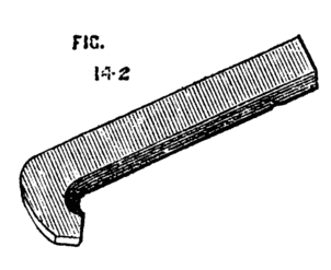
Fig. 142.
The outside must be turned in a similar manner, and a hole drilled to receive a pointed bar or wrench, for the purpose of unscrewing it when screwed up tightly. To turn up a face plate of iron or brass proceed in a similar way, but commence from the centre with a point tool. This tool is the best for taking off the rough outside of hard wood, instead of the gouge, as well as for removing the roughness of a fresh casting. It is absolutely necessary that the faces of these flat chucks, or surface chucks, be truly at right angles with the mandrel; hence it is very difficult to turn and finish them by hand. We may here also state the necessity of knowing when the slides of the rest are at right angles to each other, without which no work can be turned correctly. It is necessary to ascertain this by help of a small steel square. Once fixed truly, it is only necessary to make a mark on the quadrant (which should be marked in true degrees), by which the same position can be found again at any time. We have spoken here of the quadrant—we mean the arc, or arcs with slot—allowing the circular movement of the compound slide rest. The chief use of these is to enable the workman to turn true cones instead of cylinders, which latter will only be produced when one slide is parallel to the lathe bed. Such is the common use of the slide rest; and it will be evident from these few remarks that there is an infinity of work, not only produced with ease by its aid, but which cannot, even with expenditure of time and labour, be produced without it; hence we advise this to be the chief ambition of the tyro after he has mastered the difficulties of ordinary hand turning (and not before). The cost of a fair one for 5-in. lathe will be £5, or thereabout. At Munro's, £7 or £8; at Holtzapffel's, £10 or £12. Both the latter are of course perfect.
We have directed to tap the chuck where it is to be screwed to the mandrel with a set of three taps, or to cut it with stock and dies if an outside thread is required. In both cases more true and satisfactory work may be produced by the chasing tool. We speak of the latter as used by hand; an account of cutting the threads by help of the slide rest we reserve for the present. Mount the work in any convenient way, either driving it into a wooden chuck, or by clamping it to the face plate if you have one. Now in this way you have advantages. In the first place you need not have a drill the exact size, though it is convenient to have such a one, and also a cylinder bit. You can drill and enlarge the hole by the slide rest tools, and you can also with the slide rest ensure the perpendicular position of the hole with respect to the end. Thus it is sure to fit up close and snug to the shoulder of the mandrel. When bored thus it will be in position for chasing. It is not difficult to chase a thread in brass, as it does not chip away like wood, but cuts clean and sharp. Follow the directions already given and you will succeed in a few turns in getting the tool to run. Then let it have its own way; hold it lightly, but steadily, and do not force it either to cut too deeply, or to advance too quickly; it will run along of itself after the faintest thread is cut or scratched, and the lathe can be worked by means of the treadle all the time as soon as you have attained the knack of dropping the chaser into its place at the commencement of its cut, and suddenly withdrawing it when it has reached the bottom of the hole. A chuck thus turned and screwed entirely in the lathe is sure to prove a good fit, and there can be no better practice than to cut screws in all your brass and boxwood chucks in this way. A very good chuck to hold flat plates of brass was invented by a Mr. Wilcox, of Bishop's Stortford, some years ago—an amateur of rare ingenuity and mechanical knowledge, and who made all his own apparatus for plain and eccentric turning. The chuck, Fig. 143, as described by him in some unpublished manuscript, is made of boxwood, or may be of metal. It is a plain disc or surface chuck with three slots A B C. and a steel centre. This last must penetrate rather deeply into the wood of the chuck, but is only kept up so as to project from the surface by a spiral spring below it. Hence, when pressure is made upon its point by the application of the object to be turned, the pin recedes into the body of the chuck, suffering the work to lie flat on its surface. In the three slots are three screws, with nuts at the back of the chuck the screws pass through two pieces of brass, forming a pair of jaws, one of which is shown separately.
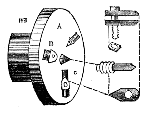
Fig. 143.
Fig. 143 shows the chuck complete. Suppose we have to face up a round disc in its central part, or to perform any surface work in which the jaws will not be in the way of the tool, the centre of the plate is marked at the back of it, and this mark laid on the central pin. The work can be clamped down by the three jaws, and the necessary work may be done. Now so far the chuck is but a simple affair, and the receding pin does not show itself to such great advantage; we will therefore suppose a plate is to be drilled at several spots; let these be marked at the back by a centre punch. It is now only necessary to bring these marks in turn upon the central point, and clamp the plate in position. Bring the point of the drill against the work and keep it up to cut by the back poppet screw. In the same way eccentric work or any operation may be done to such a plate, with the certainty that the point to be thus worked upon is precisely central with the axis of the pulley, or mandrel. Many similar applications of this chuck will present themselves to the reader upon due consideration. We present the chuck in this place because we have had occasion to speak of drilling as connected with the slide rest, and there are many pieces of work that could not otherwise be conveniently held in the desired position.[10]
Overhead Apparatus.
It now becomes necessary to speak of another addition to the lathe, by means of which the use of the slide rest is considerably extended. We mean the overhead motion. Of this there are several patterns, and we have sketched three of these. As to their respective merits we can hardly venture to speak. They all answer equally well the purpose for which they have been designed, and the turner must select according to his fancy, or, if he please, design a better for himself. A, Fig. 144, represents the lathe bed. From the left-hand standard rises a round iron rod, not less than one inch in diameter. This is not generally fixed, but is attached to the standard by two staples, a, b, which hold it securely in an upright position, but allow it to turn with its projecting bar F, F, after the manner of a crane. It may thus be turned back, out of the way, or brought into any desired position. The part F, F is made to slide up and down on the part B, and is fixed by a clamping screw D. Thus, if the cord should break and require to be shortened, the arm can be brought nearer to the bed of the lathe. Upon F, F slide two rings, or rather short pieces of tube, from which depend two India rubber springs (door springs), E, E, now procurable at any ironmonger's at one shilling each. From these hang double pulleys, or better still two single ones. These pulleys, with their attachments, are adjustable at any position on the arm F, F, which may be round or square. If considered desirable, a second standard can be added, so as to uphold both ends of this bar; but it is hardly necessary, as the latter is seldom required of greater length than half that of this lathe-bed. It is evident that the above addition to the lathe can be made complete for a few shillings. The following are more expensive, but more general, the writer having devised the above to suit his own fancy, and for his own use. In Fig. 145 A represents the standard as before, the top of which is forked, as shown at E, and sustains the ring, free to revolve in its arms, as seen in the sketch. Through this passes a bar, B B, with a heavy ball C cast on its end to act as a counterbalance to the longer arm and its connections, and to keep the cord stretched. By sliding this bar either way through the ring which supports it, the tension of the cord can be increased or lessened.[11] When in position it must be very securely fixed by the screw T, which should not simply press against it, but enter one of a row of depressions made for the purpose. The pulleys C, D are double, as in the previous plan of overhead, and are likewise adjustable at any position on the bar B, B. The only drawback to this pattern is the danger of the heavy ball slipping out and falling. We prefer to hang a weight from the end of the lever, as shown by the dotted line. This may be within a few inches of the floor, and if it should fall no harm can ensue. The third pattern, Fig. 146, is the most expensive, but although it is of a more finished appearance, and wears an aspect more stiff and stable, it is not practically any better than the last. From a standard A, with overhanging bar F, F, is suspended a frame H, by means of two coiled springs in brass boxes B, B, which keeps up the necessary tension on the cord, or rather cords, for in this case two are needed—one from the flywheel to the small pulley, and a second from the roller to the slide rest.
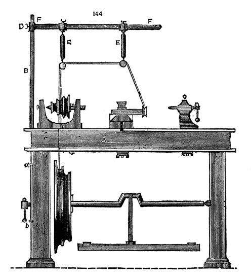
Fig. 144.
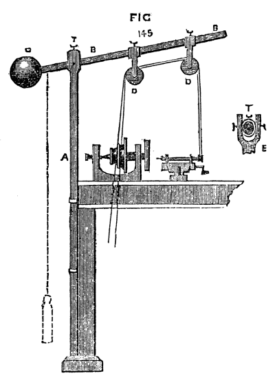
Fig. 145.
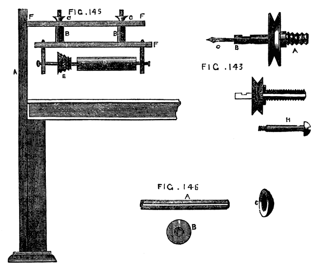
Figs. 143, 146, 148.
This roller, which may be grooved or plain, may be replaced by a second small pulley, which is capable of being slid along the round bar which forms its axle and turns with it between the centre screws. In this case the bar is made with a groove or channel along its length, Fig. 147, and a pin projecting from the central hole in the pulley enters this groove. Thus the two will turn together, and at the same time the position of the pulley is adjustable at pleasure. The tension of the springs B, B, is increased or lessened by a turn or two of the nuts C, C, just in the same manner as the spring of the safety valve is adjusted on the boiler of a locomotive.[12] The application of the overhead motion is plainly shown in Figs.143 and 144. The work is fixed in the lathe, and the mandrel kept stationary. The cord passes to the overhead directly from the fly wheel, and thence to a pulley on the screw of the slide rest, as in 143, to a drill, as in 144, or to any other apparatus at pleasure. To fit the work in the lathe in such a manner as to enable any point in the face or side to be operated upon, a division plate and index are required. The first is a round plate of brass or gun metal, 1/16th of an inch thick, drilled with holes in concentric circles. The index is a steel spring with a projecting point, which, entering any one of the holes, retains the plate, and with it the pulley, on the face of which it is fixed immovable. There are generally four circles of holes, the number in each selected with reference to its divisibility by the greatest possible number of divisions—thus 360, which is usually on the outside or largest circle, can be divided without a remainder by 2, 3, 4, 5, 6, 8, or 9—144 is a good number for the second circle, being divisible by 2, 3, 4, 6, 8, 9. The other two may be 112 and 96. The uses of the division plate are many. Eccentric cutting and drilling could not be done without its aid, and wheel cutting for clocks, or for making cycloidal and other chucks, is entirely dependent on this contrivance.
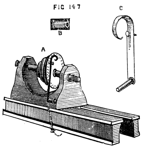
Fig. 147.
The division plate and index are shown in Figs. 147, A, B, C. The part B is a knob with a round hole through it, to take the tail of the spring C. This is shown again at C on a larger scale, to bring to view a slot which allows of some slight adjustment of the point, to suit the different-sized circles. The milled-headed screw clamps the point at any desired part of this slot. When not in use, the spring is drawn back so as to release it from the division plate, and turned down in the position shown by the dotted line.
The overhead apparatus is applicable not only to revolving cutters in the slide rest, but to other contrivances available where the latter is not possessed. There are many cases in which the back poppet may be brought into use to hold revolving drills, or stationary tools, if the resistance to their action is not too great. The only damage that can well happen in this method is to the pin working in the slot on the outside of the spindle. If this is of steel and tolerably stout and strong (being very short it cannot be subject to any very injurious strain), no harm is likely to result. With this it is possible to drill very neatly, and also to do a little eccentric cutter work, under certain conditions to be described. Screwing, or rather chasing, may likewise be done very passably. We do not, of course, advise this course when the more perfect slide rest is at hand, but there are many who are obliged to put up with all sorts of homemade contrivances, and to press into service for divers operations apparatus and tools not precisely meant to be thus used, and it is as well to learn how to act under an emergency, even if the practice is not intended to be carried out generally. The drill stock is shown in Fig. 148, in which the screw A fits into the spindle of the back poppet. If the hole in the latter is conical instead of cut with a screw thread, the drill must be made accordingly.
The pulley of brass has a hole drilled through it, and the screw is also drilled, the hole in the latter being rather larger than that in the pulley (which is tapped). The steel pin H, shown white in the sectional drawing, passes truly through the centre of the screw in which it revolves, and is screwed into the pulley. The socket of steel to hold the drill is then screwed or soldered into the opposite face of the pulley. The black part shows a flange on the screw which abuts against the cylinder of the poppet into which it is screwed. Thus the pulley, being attached to the cord from the overhead apparatus, is free to revolve upon the steel pin with great rapidity, and will carry round any drills or cutters placed in the socket B. The simple straight drill being thus worked and advanced by the leading screw of the poppet, will suffice for holes in any work held on the mandrel. On page 335, vol. ii., of the English Mechanic, this method is mentioned, and also a similar pattern of slide tool to be used for boring, being, in fact, the head and spindle of the back poppet, but instead of the standard and sole, a pin, like that of a T, to fit the socket of the rest. This has the advantage of the back poppet, but must be made on purpose, and if any special slide tool is added, a proper slide rest is by far the best. Our present purpose is to describe the use of the back poppet as a substitute for a better tool.
With the following modification of the eccentric cutter, a fair amount of good ornamental work may be done. Fig. 149 represents the back poppet with the apparatus in position. The various parts are shown separately in A, B, C, D. A is a small frame, two or three inches long, and ¾ to 1 inch wide, cast in iron, with a circular piece at the back, 1½ or 2 inches diameter. This circular piece is to be accurately divided on the edge with any even number, which is divisible as above explained. This is turned and drilled through the centre. B is a flange-shaped piece to screw to the poppet as before, and this is also accurately drilled, and the two are attached by a central steel pin, so that the two flanges can turn face to face, the outer one with frame revolving against the other. The pin must be put in its place in B, and turned at the same time as the face of B, that it may be truly central. The divisions on the edge of the outer flange are to be drilled like the division plate of the lathe, or cut into cogs, and in either case can be held at any point by a spring detent or index attached. C shows the front of the frame, with a screw down its centre and traversing slide f. The head of this screw is divided, and a small brass index marks its position; one side of the frame may likewise be divided. The small brass pulley and drill socket are fixed to revolve in the traversing nut or slide f, as shown in a side view at D. Drills of all shapes, as E 1, 2, 3, 4, may be fixed in the socket at pleasure.
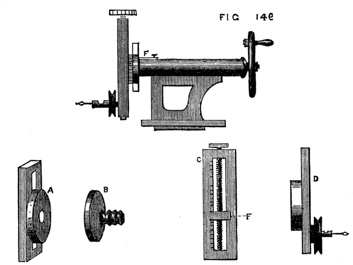
Fig. 149.
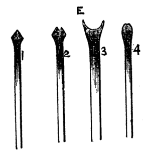
Fig. 149E.
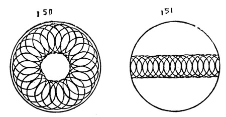
Figs. 150, 151.
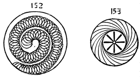
Figs. 152, 153.
It is evident that the cutter frame last described having a division plate of its own dispenses with the necessity of one on the pulley of the mandrel. Indeed it was the impossibility of supplying the latter on the face of the cogwheel of the author's back-geared lathe that necessitated the substitution of that alluded to. The latter may consequently be omitted if applied to a lathe already fitted with division plate and index. With crank-form drills the cutting edges of which may be as E 1, 2, 3, 4, or other form, such patterns can be cut, as shown in Figs. 149, 150, 151, 152, which are merely samples of the simplest combinations of circles intersecting in straight, spiral, or other lines. Although not now treating of eccentric work, we may state in passing that to produce the pattern round the edge of 150 the division plate of the instrument only is required. Select a crank-form drill which by its revolution will produce the required size of circle. Turn the divided screw head until you find upon trial that the circle will come at the required distance from the edge, and putting the lathe in motion cut the first circle. The work on the mandrel is understood to be stationary, the mandrel being fixed so as not to turn. The cutter frame is now turned on its axis, one, two, or more of its divisions, and fixed by its detent, and a second circle cut intersecting the first. This is repeated till the whole circle is completed. The straight line of circles in Fig. 151 is cut as follows:—The first circle is made as before, but the cutter-frame should be placed so as to stand either horizontally or vertically. Between each cut the divided screw-head is moved so many points according to the proposed fineness of the pattern, and no movement of the cutter frame on its axis is to be made. The spiral, 152, is simply the result of a combination of the two movements. Start from the centre by turning the screw head until the shank of the crank-form drill is coincident with the axis of the mandrel. Cut the central circle. Thence for each successive circle turn the screw head and the frame an equal number of points, and the pattern will be formed. If the divided screw head is made to take off and a handle substituted, stars formed of channelled lines, or radial flutes can be made as Fig 153, but in this case the crank form drill is replaced by a plain straight tool with a rounded end like 149 E 4. Set the tool as for pattern 150 straight across the face of the work, put the drill in rapid motion, let it be advanced by the leading screw of the poppet so as to penetrate slightly, and with the handle that has been attached to the screw of the cutter frame cause it to traverse the face of the work as it revolves. When one flute is thus cut, turn the frame on its axis as many points as required, and proceed with number two, and so on to the completion of the star. It is not necessary at present to describe other patterns. Fig. 153 is therefore merely given without special details of the method of producing it.
We must now return from this digression to speak of other applications of the slide rest. It is evident that when connection is made between the overhead and a pulley on the screw of the slide rest, the latter becomes self-acting. The speed is, however, far too great, and in addition, the mandrel is stationary. The above connection, therefore, is not practically possible, and the overhead is only connected with the pulleys of revolving drills and cutters fixed in the tool-holders of the rest. It is, however, very important to be able to form some such connection between the lathe mandrel and the screw of the rest, for the purpose of cutting screws or spirals. A little consideration will show the principle of this arrangement, from which some practical plan is not difficult to design. If, for instance, the tool simply remains in contact with a cylinder while the latter revolves with the mandrel, a simple line will be cut round its circumference; but if, while the mandrel revolves once, motion is given to the screw of the rest by which the tool is made to traverse a distance of one-eighth of an inch, the commencement of a spiral having that pitch will be made. A perfectly smooth surface, as it leaves the lathe, in which a slide rest has been used with a point tool, is in reality cut with a very fine screw thread readily discernable under the microscope. We have, therefore, only to devise some method of giving regular motion to the screw of the rest while the work revolves as usual, in order to turn plain surfaces, screws, or spirals. For the purpose of plain turning a plan is sketched by Nasmyth in the last chapter of "Baker's Mechanics," in Weale's series. A spur wheel is represented fixed to the slide rest screw, the teeth of which are alternately caught at every turn of the work, by an arm fixed to the latter, after the manner of a lathe carrier. This plan is simple, and might be to some extent used, but for one defect, due to the fact that the slides of ordinary rests are the reverse of what is required to make this plan available. The screw which advances the tool towards the work is generally underneath that which moves the tool along the surface of the work. The result is that, when the tool-holder is advanced to take the deeper cut the spur wheel is brought nearer to the arm which acts upon it, and greater traverse is thus given to the screw. This is shown in Fig. 154. A is the spur wheel, B the cylinder to be turned, C the arm or carrier. The arrow shows the direction of the movement. Now, if the lathe is put in motion, the arm will remain in contact with one tooth of the wheel until both arrive at b, giving a certain amount of motion to the screw, and thence to the tool-holder. After one cut is thus taken, the lower screw of the rest is turned to advance the tool nearer to the work, the effect of which is to cause the arm to extend further over the wheel. Suppose its position represented by the dotted line, it will remain in contact with the tooth till both arrive at c, having thus traversed a larger arc, and given more movement to the tool. Now if the frames of the slide rest were made to cross in the contrary direction so that the screw to advance the tool towards the work was above that which gave the traverse in the direction of the bed, this objection would no longer hold, and the above gearing would answer very well, since the necessary advance of the tool would not affect the relative position of the spur-wheel and carrier. In Fig. 5 of the same book, in which the gearing is effected by two cogwheels, this alteration in the rest appears in the drawing. In this case the work and rest are connected for screw cutting, and the arrangement is satisfactory and simple, and for the amateur especially is the simplest and best that can be devised. The range of screw pitches is however limited, and the rest must have a left-handed screw, or the result will be a left-hand thread to that which is cut. Hence another device has been arranged, represented in Fig. 155, A, B, C. A shows the apparatus complete. B is an arm of iron or brass which is about ¼ inch thick or rather more. This is first slipped over the mandrel screw in front of the poppet and fixed in any desired position by a screw passing through the slot a, into the face of the poppet. This slot allows the arm to be raised or lowered at pleasure and adjusted, as will be presently described. In the slot formed in the long arm B, pins D with nuts, fit, on the rounded part of which cogwheels, b, c, d, are made to revolve and to gear with each other, and with a similar wheel attached to the back of the chuck, C. The centre of the outside wheel, whether one, two, or three are used, is connected to the screw of the slide-rest. For the production of a right-handed screw, the intermediate wheel comes into play, simply to reverse the direction of the motion imparted to the screw of the slide rest. The number of teeth which it may contain is of no importance, the calculation of the change wheel teeth being only necessary with the first and last. The central one is called an idle wheel, though its work is equal to that of the rest. Thus, suppose the wheel on the chuck to contain 40 teeth, and the third wheel 20, while the former revolves once, the third will, if in immediate contact with it, revolve twice, introduce an idle wheel with 10 teeth between these two. The wheel, with 40 teeth, revolving once, the idle wheel will revolve 4 times—the third wheel twice, just as if the idle wheel was not in use. In any train of wheels, if we regard relative speed, any number between the first and last become similarly idle wheels, and the ultimate result is the same as if the first and last were in immediate contact.
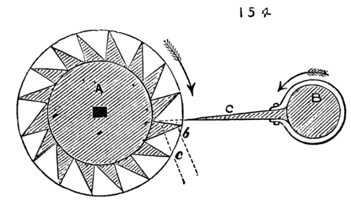
Fig. 154.
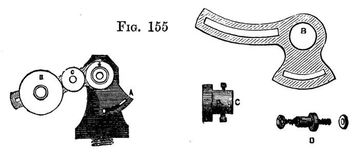
Fig. 155.
Take, for example, the following train of five wheels, even numbers being given for the sake of clearness, to represent the circumferences or number of cogs in each, Fig. 156. We have here, as the first and last, 6 in. and 120 in., and, if in contact, the first must revolve 20 times, while the latter revolves once. Interpose the three idle wheels of 10, 30, and 60 in. respectively. During one revolution of the largest wheel, the second will revolve twice, the third four times, the fourth twelve times, the fifth twenty times, the same precisely as if the first and last had been in immediate contact. The range of a slide rest-screw is quite long enough for many purposes of the amateur, and a connection thus made between the mandrel and such screw is what may be termed a miniature of the arrangement adopted in the large self-acting lathes. In the latter, however, a leading screw is added the full length of the bed along which the slide rest travels bodily. We may, therefore, consider the screw of the slide-rest a leading screw, and make use of the rules applied in the case of large lathes to decide the proportions of wheels required to cut a given screw. It is plain that when the pitch of the required screw is greater than that of the leading screw, the revolution of the latter must be at a quicker rate than the former. If, for instance, a spiral is to be cut, like the Elizabethan twist, containing but one perfect thread in two inches, while the leading screw contains twenty threads in the inch, or forty in the 2 in., the latter must be arranged to make forty revolutions while the former makes one, because it takes 40 revolutions to carry the tool along 2 in., which is the pitch of the required spiral. The two outside wheels must therefore bear that proportion to one another. Forty to one, however, would be a practically difficult ratio, to place as described, even a pinion of ten teeth on the leading screw requiring 400 teeth on the chuck. Hence a different arrangement would be necessary if such very great difference exist between the pitch of the leading or rest screw and that to be cut. The same obvious difficulty would occur where a very fine screw is required, and the pitch of the leading screw is coarse. This will have to be referred to again. One example, therefore, of the method of overcoming this difficulty will suffice. A train of wheels is shown in Fig. 157, of which A has 60 teeth, B 10 teeth, C, on the same axle and united to C, 30 teeth, D 20 teeth. While A turns once, B will turn six times, C necessarily six times also, D nine times. In this case, if the first and last had geared together D would have made but three turns, while A made one.
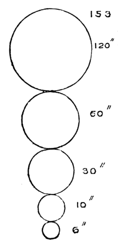
Fig. 156.
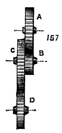
Fig. 157.
The following is an easy method of calculating a series of such change wheels:—
Write down the number of threads in the screw to be cut, and also the number of threads in the leading screw; multiply both by any convenient number likely to give such results as to tally with the cogs in the set of change wheels. Suppose it is desired to cut eight threads to the inch, and that the leading screw has two threads in that length. Then:
8 ×10 80 or 8 ×15 120 or 8 ×20= 160 &c.
2 20 2 30 2 40
If you have either couple of these wheels, you can put one on the leading screw, and another on the mandrel, and fill up the intermediate space with dummies.
If the above is inconvenient, or the wheels are not to hand exactly as required, proceed thus. If you have the wheel for the mandrel, and the one you wish to use for the leading screw has only half the proper amount of teeth, it is evident that the leading screw would revolve twice as fast as required, for they are proportioned as two to one—or if I have the proper wheel for the leading screw, and the wheel I wish to use for the mandrel has twice the proper number of teeth, it amounts to the same thing. You can get over the difficulty by using any two wheels which are in the proportion of two to one (say 20 and 40, 30 and 60, 40 and 80, &c.), and coupling the two firmly together, so that the larger wheel of the two works into the mandrel wheel (or dummy working into the mandrel wheel) and the smallest into the screw wheel (or its dummy); if the speed is wrong in the contrary way, so that the case is reversed, the coupled wheels are made to gear in a reversed direction; and whatever may be the amount of error, whether such as to cause either mandrel or screw to revolve ⅛, ¼, or ¾ too slow or too fast, the same arrangement may be pursued, the coupled wheels bearing that proportion to each other. The above method was communicated to the English Mechanic by a working man, James Connor, and is perhaps as easy as any; but tables are published of change wheels for any pitch, with any thread of leading screw. Where it is not possible or inconvenient to apply the above arrangement, and where only a few pitches are likely to be needed, another method can be arranged by connecting the lathe pulley to the overhead motion and thence to the screw of the rest. Such an arrangement is shown in Fig. 158. A is the fly wheel, B mandrel pulley, C, D, pulleys on the overhead, E pulley and screw of the slide rest. To facilitate calculation, let diameter of C equal that of the part of the mandrel pulley that drives it, by which it will revolve in the same time. The calculation of the sizes of pulleys, D and E, will be the same as for the cogwheels of the screw-cutting lathe, circumference and number of cogs being, so far as calculation is concerned, the same thing. Let the leading screw have eight threads to the inch, and let it be required to cut a spiral of two threads to the inch. Proceed as before by dividing the required number of threads to be cut by the number on the leading screw 2-8 = ·25. The pulley on the leading screw will be therefore one quarter the size of that on the overhead (which is virtually that on the mandrel as it revolves at an equal speed with the latter). The overhead pulley may be conveniently twelve inches diameter, and that on the screw three inches. While the mandrel makes one revolution the screw will make four, advancing the tool half an inch, and cutting one thread of a spiral in that distance. The next revolution will advance the cutter a second half inch, cutting a second complete thread of spiral. Two threads will, therefore, have been cut in the space of one inch as desired. By the above method short screws and spirals of divers pitches may be cut at pleasure. The practical difficulty in this plan is due regulation of the various speeds.
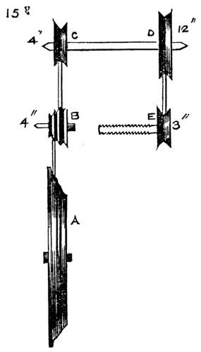
Fig. 158.
We here introduce a modification of self-acting lathe for cutting Elizabethan twist described by Mr. Wilcox in his MS. before alluded to. The work is here done by a leading screw and toothed gearing, the principle being that of the ordinary machine lathe. A chuck, A, with cogwheel attached holds the work as usual, the back centre being also required. The cogwheel gears with one of less diameter attached to the end of the guide-screw B. On the latter works the rest C, in which is a nut of the same thread as that on the guide screw, and which holds the tool in a notch or hollow upon its upper part. The tool is then used by hand, but is guided in its course along the surface of the work to be turned. This guide screw, with the rest and cogwheel, is mounted on a board as a separate piece of apparatus, and is, when used, clamped on the lathe bed. As the rest is after all little else than a large nut, it must be prevented from turning round, and must be arranged to bear the pressure of the tool, relieving the long screw from the strain that would be thus caused. This is effected by a long flat bar—like the rest of a chair maker's lathe—extending the full length of the bed shown here at E, and supported by standards F, F. A projecting part of the rest bears upon this, and slides along it with the tool. The work is begun with the rest on the right hand, and some care is necessary as it nears the cogwheel on the left, when the work must be stopped and the whole run back by hand to its starting-place. This is one chief defect in this apparatus, for the rest very quickly traverses the length of the screw, and great delay is caused by having thus constantly to stop the lathe and reverse the motion. The closest attention is also necessary to prevent the rest from overrunning its mark and striking the cogwheel. It is evident that by using different pitches of cogwheels, many screws of varied threads can be cut in the above lathe. There is, however, another defect in the above tool not noticed by the writer of the MS. from which the description is taken, namely, the difficulty (common to all such contrivances for turning wood), of obtaining the requisite speed. If the work is put in rapid motion, without which wood will not be cut clean, the movement of the rest will be so rapid also, from the effect of the multiplying wheel, that the tool will be carried from end to end in a few seconds. We will therefore proceed to describe a modification of this and similar apparatus, which allows the tool a slow traverse lengthwise of the work, but gives it immense rapidity in the necessary direction. The following is applicable to the lathe described above, to the ordinary slide rest worked by hand, or to the large self-acting screw-cutting lathes used in manufactories, and is specially adapted for cutting spirals or other patterns in wood. In the Fig. 160, A represents a shank, which may be made of any shape to fit particular patterns of tool holder. This shank is turned up and becomes a cylinder at B, like that of the ordinary revolving cutter. This part is bored, and fitted with a steel spindle, which should be of strength proportionate to the size of stuff likely to be operated on. One end of the spindle is fitted with a brass pulley, from which a cord is to be attached to the overhead apparatus, the other end terminates in a round or hexagonal boss, D, round the margin of which are securely held, by means of bridles B1 or other simple contrivance, a pair or more of small sharp gouges. This apparatus is put in the tool holder of the slide rest, set to the angle that corresponds with that of the screw or twist, and put in rapid revolution by means of the overhead apparatus. The whole rest, or merely the upper part, is then put in motion by one of the before-named means, and the tool advanced to make a cut. However slow the movement of the rest may be, the cutters move with such velocity as to make clean and beautiful work.[13] This may be applied to the slide-rest of the twist lathe, just described, or any similar apparatus. In the overhead, a roller, supplying the place of the second pulley, as described in a previous page, will allow the second cord sufficient power of traverse to keep up a proper position in reference to the pulley C. Revolving cutters on the same principle as the above, have of late years come into extensive use in wood-cutting and carving machinery. The steam planes now used in the preparation of flooring boards, the spoke turning lathe, moulding and shaping machines for wood are all thus fitted. The gouges or other cutters used must not be placed radially, but as tangents to the circumference of the boss in which they are fixed. An improvement upon the simple bridle to hold the cutters would be the substitution of Babbage's tool holder, four radial arms being substituted for the metal boss above alluded to. This tool is described and figured in Holtzapffel's "Mechanical Manipulation," to which the reader is referred for an accurate description. It chiefly consists of a shank turned up at the end like Fig. 161, the outside, at B, being rounded to fit hollow gouges such as Fig. 161H; against this the hollow of the gouge is laid, and opposite to it, at C, a small piece like D. A band or hoop, E, is now placed over both the above, and between the two a wedge-shaped piece, F, which is intended to bring a strain upon the hoop and tighten it round the gouge. This last piece is attached to the shank or holder by a screw passing through it into the shank. The tighter this screw is worked the lower the central wedge is drawn down, and the tighter the hoop is made to embrace the tool. This holder is also modified to suit flat chisels. The tool cannot possibly slip, but can be released in a few seconds if desired. Such a termination of two, three, or four arms revolving on a spindle in place of the boss would form the best possible circular cutter for shaping lathes. The above lathe for producing Elizabethan twist introduces the reader to self-acting, screw-cutting, and machine lathes, such as are used in all large manufactories. Hand-turning, indeed, except in such light work as turning up the heads of small bolts, and finishing up work which, from peculiarities of form, cannot easily be done by self-acting tools, has become a thing of the past in factories of any pretensions; hand labour, in fact, not only no longer pays, but is quite insufficient to meet the requirements of the present age. Take, for example, a piston-rod requiring to be as "true as a hair," to use a common expression, from end to end. The traverse of an ordinary slide-rest would only enable us to turn a short length at a time, and the result, when accomplished, would not be satisfactory. With a self-acting lathe the tool traverses in a perfectly straight line from end to end, is returned to its starting-point by a quick traverse, and the movement repeated until the proper dimensions are attained. The process is not absolutely rapid, because time is requisite in cutting iron and steel, but the work is executed as speedily as the nature of the metal to be cut will allow, and the execution is perfect. Of late, however, even the above has been improved upon, for two cutters are used at once—one on each side of the bar, so that by one traverse of the rest a cut of double depth is taken, and the tendency of the work to spring away from one tool is counteracted by the operation of the other. But we require something more than speed in the present day. We must have work of absolute truth of measurement. What would our ancestors, or the immortal Watt himself, think of measuring work to the hundredth part of an inch, yet it can be and is done to the thousandth part. I believe I am correct in saying that Whitworth constantly gauges work to that or even a higher degree of nicety. It is not too much to assert that the best engines of the present day really work with the precision of clockwork, and even the bore of an Armstrong or Whitworth gun is executed with no less accuracy and precision. Look again at that ponderous affair, the steam hammer, so ponderous as to require a depth of solid masonry and timbers to sustain the force of its terrific blows. In a few minutes a solid mass of metal is reduced to a flat plate such as would have taken the united strength of a dozen men wielding the heaviest sledge-hammers for an hour at least. The ground beneath the feet of the spectator trembles at every blow of the machine. The work is done, and behold! with a touch the same ponderous concern becomes a nutcracker, not even injuring the kernel when it breaks the shell. Such is one of a hundred specimens of accurate workmanship carrying out in practice the clever designs of the mechanical engineer. Sweep away self-acting machinery, and such work would become a simple impossibility. Again, so long as turning, boring, planing, and such work was performed by hand alone (even after the introduction of the slide principle), an attendant was required at each machine. Now that the latter is contrived to regulate its own movements, one man at two or three lathes is sufficient. Thus the same article that was once imperfect and costly, owing to the demand on skilled labour, which was difficult to procure and at best inefficient when procured, has now become cheap, and to all intents and purposes perfect; and although the demand for such work increases year by year, self-acting machinery being constantly improved and simplified, enables the manufacturer to keep pace with the demand.
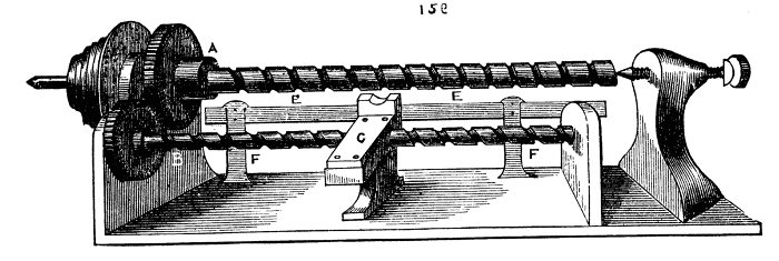
Fig. 159.
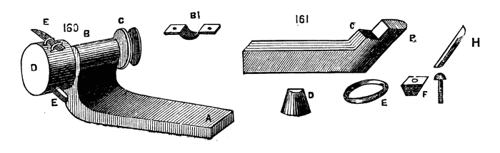
Figs. 160, 161.
The advantages of self-acting machinery are of course chiefly confined to the trade, and it is not often that the mere amateur requires such aid. Indeed, the expense necessarily attendant on the fabrication of these machines deters the great majority from making such a purchase.
Self-acting and Screw-cutting Lathes.
The first requisite for fitting up a lathe for screw-cutting and plain turning is the fitting a guide-screw, and adding a saddle to the slide-rest. But it must be observed that the ordinary mandrel of small foot-lathes, which works in a collar and back centre, is not convertible, and must be replaced by one working through two collars, so that a part may project at the opposite end to that intended for the chucks. On this projection various cogwheels have to be fitted. Now there are divers patterns of mandrel suitable for the above purpose; some are perfectly cylindrical, some have one conical part, some are fitted with a second cone, independent of the mandrel, and which slides upon it, and can be adjusted by means of regulating nuts. This latter being a good pattern, when well constructed, we shall first describe in detail. In Fig. 162 is shown A, the mandrel complete, with fittings in section, but without any of the change wheels. The cone a is forged on the mandrel, which then becomes cylindrical. The cone is figured too large in proportion to size of mandrel; the latter should be represented as much more substantial. At b the second cone slides on, the latter shown again at B. It is bored truly, and a slot cut to fit a feather on the mandrel. Thus it will slide along it, but must necessarily turn with it. Beyond D on the left are two screwed parts, one slightly larger than the other, one being made with a left-handed, the other with a right-handed thread. On these screw the two nuts, d, e, which drive the movable cone towards the right, causing it to fit more tightly into its collar, and also by the same movement tightening the fixed cone in its bearings. The mandrel is thus readily adjustable in the collars, and can be made to run very truly and easily without shake or endlong movement. Any pressure, however, against the front, such as would be caused by drilling, would jam the front cone in its collar, and tend to loosen the other. This is counteracted by the part f, g, with its screw, h, against which the end of the mandrel bears. That this form requires good workmanship is evident, for there are three points, or bearing surfaces, to be brought into a correct line, and the slightest deviation will cause the mandrel to jam in some part of its revolution. The nuts screw up in opposite directions to counteract the tendency in either to screw up more tightly, or to become looser by the revolution of the mandrel. On the whole the above is a good form of mandrel; if it has a fault, it is a slight tendency to work heavily. The next form is that of the ordinary mandrel, with single cone, but a second collar is added, which is cylindrical, through which the mandrel passes, and it then abuts on the sustaining screw as before. This is shown in Fig. 163, with the addition of the wheel, which is to be connected by intermediate wheels and pinions with the leading screw. If the conical collar is replaced by a cylindrical one, so that two similar bearings are made use of, a shoulder becomes necessary to prevent the mandrel from slipping endwise. The collars must also be split as in Fig. 164, so that they can be tightened up as they become worn. Either of the above forms of mandrel can be used; each has its advocates, and not unfrequently all may be found in different machines in the same manufactory. The bed of a self-acting lathe requires to be accurately surfaced, and formed by the planing machine with two V's or edges bevelled underneath, as 165 b, b. The saddle of which we have spoken is a flat plate of cast iron fitted with V pieces to match the bevelled edges of the lathe bed, along which it slides truly, its under-edge being planed. To this plate the slide rest is attached securely, either turning when required on a central pin, and being clamped at any desired angle, as before stated when treating of the compound slide rest, or, when this movement is preferred to be given to the upper slide, fixed permanently by nuts and screws. The saddle is represented detached in Fig. 166. The principle of the self-acting lathe is very simple. Motion is given to the screw by means of cog wheels geared with the mandrel, a nut fitting the screw is attached to a hanging bracket of the saddle, and this with the rest is thereby carried along the bed. It is necessary, however, to add some contrivance for instantly throwing the screw out of gear, without the necessity of stopping the lathe itself. There are many ways of effecting this, the most common being the use of a split nut, which embraces the leading screw when the two halves are brought together upon it, but which is instantly freed by separating them through the action of levers and cams, or other simple mechanical contrivance. In Fig. 167, a is the bottom of the saddle from which depend the brackets E, E. The nut B, B, which is divided across the middle, slides up and down between these brackets, D being the leading screw which they embrace when closed. The movement of the halves of the nut is effected by the lever c, in the form of the letter T moving on a centre pin at K, and having two links, D, D, attached to the halves of the nut at one end, and to the ends of the cross lever at the other. A connecting bar pivoted to the part, L, is attached to a lever and handle, by which motion is communicated to the lever. When this rod is moved in the direction of the arrow the links will cause the nut to close and vice versa. The next form, 168 and 169, represents the split nut attached to two arms, A, A, hinged together at E. B, B, are slots in which work the pins attached to the cross head of the levers C, C. A heavy knob of iron keeps the latter in the position to which it may be moved. In 168 the pins keep the arms and nuts apart. When the lever is thrown over, as in 169, the nut is securely closed and held in gear. This form requires to be fixed to the lower part of a bracket attached to the saddle of the slide rest, such as is shown at B, C, Fig. 170. In this figure, A is the bottom of the saddle E, E, the V piece, that on the left, having an adjusting screw to tighten it on the lathe bed when necessary. At F is a projecting piece of the saddle fitting accurately between the lathe bed, and kept down by a screw with bed plate underneath. This serves to steady the movement of the saddle and relieve the pressure and strain upon the V pieces. The bed-plate may be cut out to fit the lower part of the bed on which it slides, both being planed for the purpose, as shown at H.
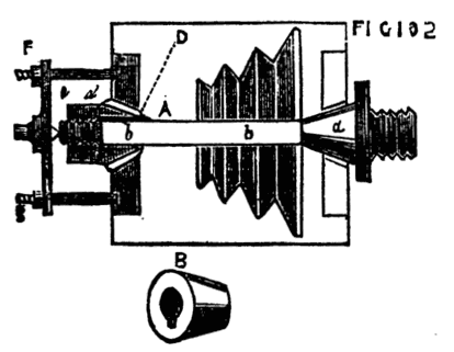
Fig. 162.
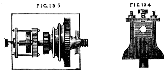
Figs. 163, 164.
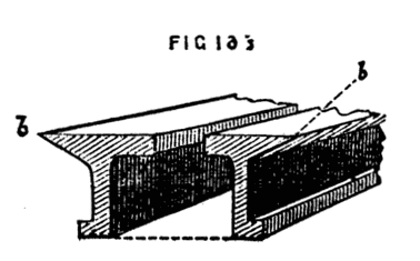
Fig. 166.
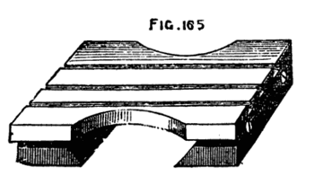
Fig. 165.
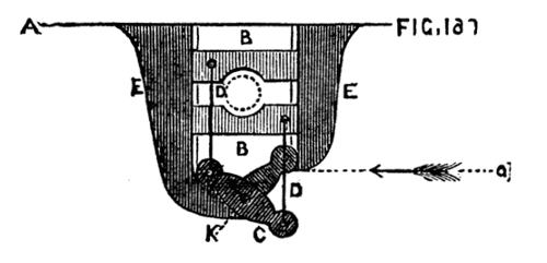
Fig. 167.
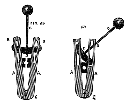
Figs. 168, 169.
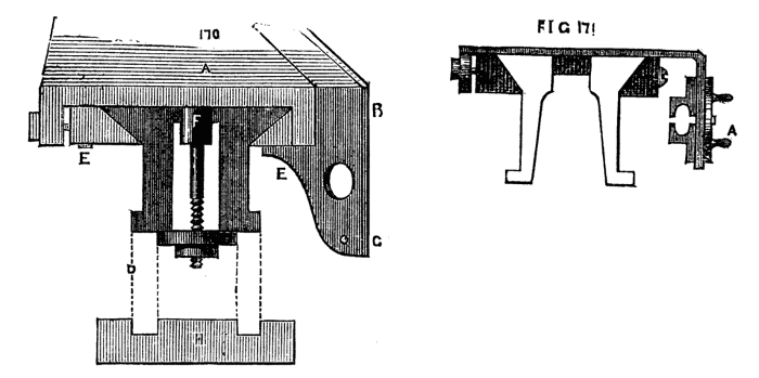
Figs. 170, 171.
In Fig. 171 the half nuts slide up and down on the front of the saddle, and are moved by a circular plate on the outside. The action is very similar to that of Fig. 167, intervening links, attached to the plate and to the halves of the nuts, giving motion to the latter as required. Cams and eccentrics of varied forms are also made use of for the same purpose, every lathe maker devising new and improved movements from time to time. There is indeed little difficulty in arranging a satisfactory method, the best being that which is under easy control, of adequate strength, and not likely to be easily disarranged by the rough treatment it is liable to receive at the hands of the workman. The leading screw may either be placed on the outside, in front of the bed next to the workman, or inside between the bearers. The former is preferable as being more accessible, but it is rather more exposed to injury. When between the bearers the large saddle of the slide rest serves to protect it from the falling chips and shavings of metal which, mixing with the oil, are apt to clog the threads and add to the friction of the parts, besides increasing considerably the wear and tear, and no accidental blow is likely to reach the screw thus protected on both sides by the lathe bed. Nevertheless, all the various parts of a machine should be made as accessible as possible, and, with the exercise of ordinary care in its preservation, the position outside is on the whole the best. If the lathe bed is very long, it may be desirable to support the screw by allowing it to rest on friction wheels fixed to the saddle at both ends, or by allowing it to pass through a pair of brasses. Thus, as the saddle is often two feet in length, such bearings at each end, with the split nut between the two, form points of support which go far to prevent the screw from jagging or bending in the middle from its own weight.
The general arrangement of self-acting tools is similar with all the makers. Fig. 172 is a drawing of such a tool from a sketch of Eades & Son, an old firm in Lichfield-street, Birmingham, the screw being here placed in front. Whitworth, the eminent mechanician of Manchester, makes many lathes with the screw between the beds. He also uses a double slide rest, with a tool working at each side of the piece to be turned, which cannot thus spring away from the cut. This is called a duplex slide rest. By this method double the cut is taken, and the strain upon the work lessened. In addition to the screw there is usually a rack attached to the lathe bed, on the furthest side, and a cog wheel working upon this, attached to the back of the slide rest saddle, is turned by a handle in front of the rest, Fig. 173. This enables the workman, after having, by means of the screw, completed the cut to the end of the work, to run the rest back again very quickly, having first released the split nut from the screw. The tool is thus brought into position for the next cut far more rapidly than could be managed by reversing the motion of the screw. This is called, therefore, the quick return motion, and is almost always attached to the larger class of machine-lathes. Before entering upon the details of other forms of gearing, and the arrangement of change-wheels for cutting screws or for plain turning, we shall introduce a few remarks upon the often-repeated question as to the advisability of self-acting lathes for the purposes of the amateur. It must be remembered that the chief object of such a lathe is the manufacture of large screws, long shafts, and such work as the piston rods of engines, requiring perfect accuracy from one end to the other. Boring cylinders and similar work is now generally done in an upright or vertical boring machine, which is for many reasons more convenient. This class of work, of course, the amateur has nothing to do with. The traverse of an ordinary slide rest is generally adequate for surfacing or boring to a length of six inches, which is sufficient for most purposes, and can readily be done by turning the leading screw of the rest by hand. Then, as regards screw cutting in the lathe, it is questionable whether it is not easier to turn up the blank and cut with stock and dies. The thread thus formed is a copy of that of the tool, and the latter, as made by Whitworth and other first-class makers, is as perfect as machinery directed by talented workmen can produce. If it is really desirable, however, to make use of the lathe for this purpose, the plan already suggested is generally applicable, namely, gearing the leading screw of the slide rest to the mandrel, either by means of change-wheels attached to an arm, or by connection with the overhead pulleys. There is, in addition, a plan of attaching a pair of dies to the tool holder of the rest, after detachment of the screw from its nut, which may be available in some cases. There are also screw plates made in two halves, the plates being divided lengthwise and clamped together at pleasure, admitting of application to any screw-blank while revolving in the lathe; and, lastly, pairs of dies, fitted like pliers, can be similarly used by hand without any slide rest. On the whole, then, it will hardly pay to give £50, or £60, for a screw-cutting lathe that is merely destined for small work; that can be done sufficiently well in a common lathe with hand motion to the rest. For cutting short screws, such as those of boxes, a convenient and practically useful contrivance is still a desideratum. The traversing mandrel is, no doubt, the best, but it is an expensive pattern, if well made, and it is necessary to sacrifice, in a measure, general utility to questionable and certainly partial advantage. Turning is, moreover, an art, and to attain skill in it, perseverance and practice are necessary—hence the zest experienced in its pursuit by the real lover of it. This perseverance pays, and to attain the skill required to trace a short screw with the chasing tool is within the reach of any one who desires to accomplish it. The art once acquired, the desire for a traversing mandrel ceases; for no good workman would accept a contrivance of the kind when he can more easily and quickly accomplish his end without it. Writing this for the special benefit of amateurs, we would strongly advise them not to throw away money to purchase the means of doing what after all they will probably never, and certainly only seldom, carry into practice. The pleasure afforded by all the mechanical arts is greatly enhanced by meeting with and triumphantly surmounting all sorts of difficulties. Let it be a standing rule of our readers to make use of the appliances at hand instead of seeking others which only save trouble and render skill unnecessary. What can be more aggravating than for an amateur, with his hundred guinea lathe and chests of tools, to be obliged to take his work to a mechanic, and to see him, whose whole stock might be bought with perhaps a tenth part of the money, take in hand and finish with ease what has baffled the skill of his more wealthy patron? The common fault of the amateur is undue hurry. To him time is seldom an object, yet the mechanic, to whom it is so precious, readily spends more upon his work. He never hurries, never compromises, but with lathe and file fits the several parts of his work with the most patient care and practised skill. The result is at once seen when his productions are placed side by side with those of the zealous but too hasty amateur.
It remains, as previously described, to arrange certain cogwheels gearing with each other upon the spindle of the mandrel and upon the end of the screw, to enable the workman at pleasure to vary their ratio of speed, in order to give him the means of regulating the pitch of thread to be cut. For this purpose a set of change wheels is supplied with the screw-cutting lathe, the number of cogs in which usually commencing at fifteen, increase by five, until the number one hundred and twenty is reached, then increasing by ten up to the complete set. Duplicates of some numbers are also convenient. The method of finding the proper sized wheels is, of course, based upon the proportion borne by the required pitch to that of the leading screw and one form of calculation for the purpose has already been given. Thus, supposing the leading screw to have two threads to the inch, it must revolve twice to move the tool that distance, and if we wish to cut a screw of ten threads to the inch, the work on the mandrel must revolve ten times while the leading screw revolves twice, or, which is the same thing, the mandrel must revolve five times while the screw revolves once. The cogs in the wheels must therefore be in the proportion of five to one, say fifty on the screw and ten on the mandrel, with an idle wheel on the stud to cause the motion of the tool to be such as will cut a right-handed thread, or to cause the mandrel and screw to take the same direction. Now, it seldom happens that two wheels and an idle one will give the requisite speed to the tool, and the number of cogs required soon mounts to inconvenient numbers. In this case, therefore, according to a principle already laid down, a stud-wheel with a pinion attached to the same, is placed in the train of wheels, and the object readily attained. A modification of the rule of calculation may make the system of change wheels still clearer. Let the pitch of guide screw be as before, namely, two threads to the inch, and let five be required. Place the numbers thus, 2-5, and divide both into their factors, twice one, or 2 × 1, and twice two and a half, or 2½ × 2.
2 1 / 2½..2
Now, it is certain you can have no wheels containing half notches, nor of such small numbers of cogs, therefore multiply by any convenient numbers—ten, for instance, which give
20..10 / 25..20
This is all that is needed. Put a wheel of twenty cogs on the mandrel, and let it work into one of twenty-five on the stud, the latter carrying a pinion of ten cogs, driving one of twenty cogs on the screw. To prove this, as before, the screw must make two revolutions to carry the tool one inch, and during that time the mandrel (carrying screws to be cut) must make five revolutions. Let the screw wheel revolve twice, the pinion of ten teeth will revolve four times (twice 20 = 40 and four times 10 = 40); but as the stud wheel and pinion are as one, and revolve together, the stud wheel must also revolve four times (4 × 25 = 100). Thus the mandrel wheel will revolve five times as required (20 × 5 = 100). No other method is so easy to understand and work as the above. To give full details and provide working drawings of the various screw cutting lathes by different makers would be to extend the present series to an unnecessary limit, but we shall nevertheless describe another method by which these lathes with traversing rests are made self-acting when screw cutting is not required. Instead of a leading screw extending from one end of the lathe to the other, there extends a bar of steel about the diameter of the screw with a key groove or slot from end to end. This bar is supported in bearings at each end, and carries upon its surface a ferrule of steel with a screw cut upon its outside similar to Fig. 174, where A is the bar and B the ferrule. The pitch of screw is coarse, being similar in its object to the guide screw previously described. A pin fixed into this ferrule falling into the slot permits it to travel along the bar but causes both to revolve together when the bar is put in motion by means of a cog wheel or strap pulley at one end. Along the same side of the lathe bed, and level with the surface, is a rack, C, upon the face of which works a pinion, D, carrying on the same axis a cog or rather worm wheel, E, to gear with the screw ferrule. The bearings of this axis are secured to the saddle of the slide rest. Consequently, when the bar revolves, the screw is also put in motion, the wheel, A, Fig. 175, and pinion, B, partake of the movement, and the latter traverses the face of the rack, carrying the saddle with its rest and tool holder along the bed of the lathe. By this movement the screw ferrule traverses the bar as it revolves, thereby virtually becoming a long leading screw. In Fig. 176, which is a view from above, looking down upon the lathe bed, A is the rack, B, B, the saddle cut away to show the rack and pinion C; E is the worm wheel, D the long bar, the screw ferrule, being under the worm wheel, is not visible. As above arranged it is evident that the ferrule might escape from the worm wheel instead of proceeding on its proper course. This is prevented by its lying in the hollow of a bracket attached to the rest, as Fig. 177, A and B. This retains it in contact with the worm wheel, and also becomes a support to the long bar. Fig. 174 shows the side of the lathe that is furthest from the operator. The axle of the worm wheel and pinion carries a handle on the near side to give the workman power to use the rack by hand as a quick return movement. The above is frequently attached to those lathes provided with a long screw, the latter being on the near side and the bar on the other. Thus, the same lathe can be used for ordinary or screwed work. Whitworth, however, commonly uses the long screw placed between the beds or bearers of the lathe for screwing and surfacing, instead of adding the apparatus just described. A long screw being, however, an expensive affair, ought to be carefully cherished, and when the work is such as the bar will suffice to accomplish, it may be well made use of to preserve the screw. There is an arrangement for forward or cross-feed in the above apparatus, the principle of which is the connection of the cross screw of the rest by means of a pinion, either with the worm wheel or with a cogwheel on the same axle. When this is put into gear the rack and pinion are disconnected. It is also necessary to provide a method of reversing the motion of the long screw bar, especially when the cross feed is used in surfacing. There are several modes of accomplishing this, the best being the following, Fig. 178, which is a simple expedient applicable to lathes or other machines. A is the end of the screw rod, with bevel wheel attached, B, C, are similar wheels on the axle, D, the latter being movable endwise in its bearings by means of the lever handle; E, D, is the driving axle. By moving the lever to the right B is geared to A. A movement to the left brings C into connection. Between the two, both wheels are thrown out of gear, and though they may continue to revolve, the screw bar will remain still. By this contrivance the motion of the leading screw is reversed or stopped in a second, with the advantage of its being unnecessary at the same time to stop the working of the lathe altogether. It has probably struck the reader that as the size of the change wheels are various, there would be in some cases an impossibility of their touching so as to gear together. This is partly remedied by the interposition of dummies, or idle wheels, and partly by the following arrangement. The stud wheel, or dummies, as the case may be, are not upon axles fixed to the lathe-head or end standard, but upon such an arm as Fig. 179, which turns upon a pin at A, and carries in the slot the pins upon which the different wheels centre. These pins being made similar to B, C, can be placed at any position in this slot, and are fixed by a nut underneath. This arrangement gives considerable power of adjustment, and enables the workman to place together wheels of various sizes according to his need. It would not be by any means difficult to arrange the above lathe for screw-cutting, especially if the pitch of the required screw is not of great importance. An amateur's lathe might be thus fitted to serve a good many purposes, although a leading screw is to be preferred as the more complete and perfect arrangement. It cannot, however, be denied that there is great friction produced by the worm wheel and endless screw, which soon tells its own tale by the wear and tear produced, and the power is not so economically used as it is when the screw works in a nut. Expediency, however, in this, as in many similar cases, must decide for or against the arrangement in any particular case. It is, at any rate, a good addition to a lathe provided with an ordinary leading screw, more especially in the facility with which it can be arranged as a self-acting cross-feed to the rest when used for surfacing.