THE LATHE AND ITS USES. (continued 4)
Reading edition
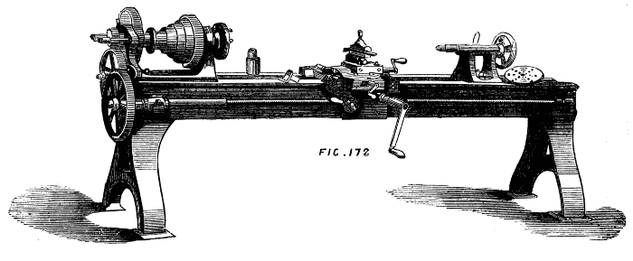
Fig. 172.
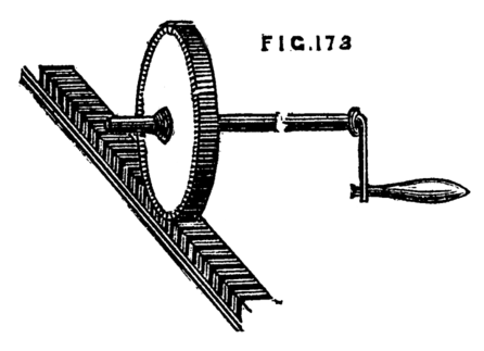
Fig. 173.
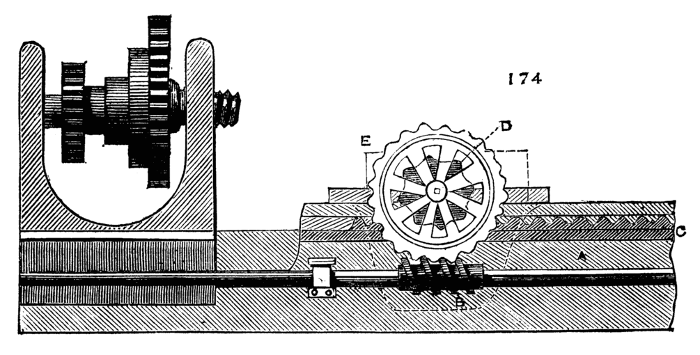
Fig. 174.
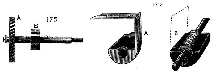
Figs. 175, 177.
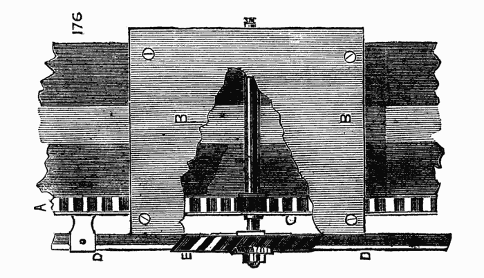
Fig. 176.
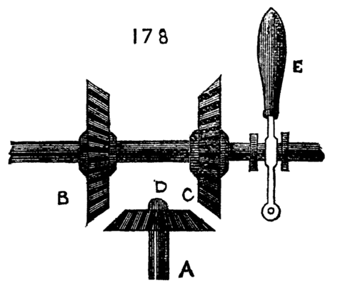
Fig. 178.
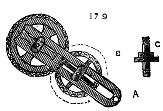
Fig. 179.
Wheel Cutting in the Lathe.
Among the various uses to which a lathe may be put, wheel-cutting is one of the most important, so many pieces of mechanism requiring cogged wheels of various pitches and forms of tooth. By the aid of the slide rest such an apparatus as figured may be readily arranged, and the work rapidly and accurately performed. The guide by which the cogs and spaces are determined is the division plate already alluded to, and which is not visible in the present drawing, but the index of which is shown at G. C is the cutter frame with a side pulley (one on each side) to conduct the catgut band from the revolving spindle to the overhead motion on to the flywheel. The spindle carries a pulley for the cord and a cutter wheel, I, to which an exceedingly rapid evolution is given. There are many patterns of these wheels, the edges of which, cut into teeth like a fine saw or file, are the exact form of the spaces required between the cogs; hence, some are rectangular, some have a triangular section. The thicker the wheel to be cut the larger should be the cutter, so that the bottom of the cut may be virtually level. In Fig. 181 another form of cutter is shown, which if put into sufficiently rapid motion answers as well, if not better, than the wheel-shaped cutters. It is a simple short bar of hard steel, with the edges bevelled in alternate directions, fitted into a slot in the spindle and held by a wedge or screw. The shape of the end is as before, a cross section of the space between two teeth. The cutter frame is here arranged to fit into the ordinary tool-holder of the slide rest, but the form may, of course, be varied at pleasure. It will be noticed that the slide rest, as delineated here, is different to that of which details have been given. It is made without the sole, and fits into the socket of an ordinary rest. Thus it can be turned on a centre, and becomes, to all intents and purposes, a compound slide rest. It is on this plan the small ornamental turning rest of lighter construction is made. The spindle fitting the socket projects from the centre of the lowest frame, and is cast in one piece with it. If the apparatus is compactly and strongly made, it becomes a very serviceable form, and is much used for the small lathes in sea-going steamers. The sides are made very short, so that the extent of traverse is small. We may here mention an addition to the rest socket, enabling the workman to raise this kind, or that used with drills and cutters, which is simple and convenient. Inside the iron socket a few turns of a screw are cut, and a second socket of brass with an outside thread is made to fit into it Figs. 182 A and B, the latter being a section. The edge of the inside socket is sometimes milled round, to facilitate holding it by the thumb and finger. In this way the height of the slide rest, or tee of the common rest, is adjustable to a great nicety.
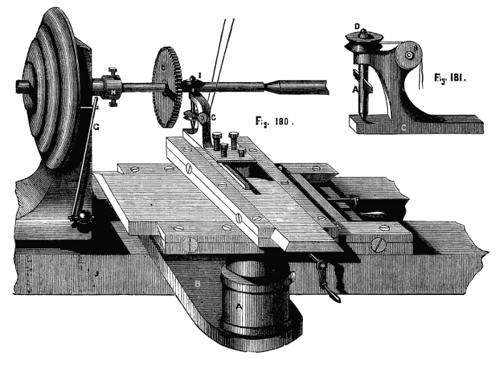
Figs. 180, 181.
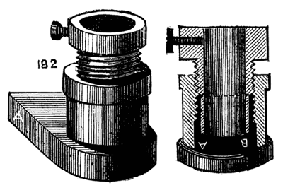
Fig. 182.
When a wheel is to be cut of large size, or of substance exceeding that of clock-wheel work, the above method is not suitable. The wheel is then generally laid flat, and the cogs are shaped by a slotting machine, the chisel of which has a vertical motion. The lathe is then no longer used; as a separate machine is more convenient and economical.
A most serviceable addition to a lathe, especially an amateur's foot lathe, is the circular saw, with guides for cutting parallel, taper, or mitred work. Great rapidity of work is thus combined with perfect accuracy. A five-inch lathe will of course take a saw nearly ten inches diameter, but it is not advisable to attach one of quite this size, for the larger the saw the greater is the leverage against which the turner has to contend, and the friction caused by a deep cut in stuff of two inches diameter is quite sufficient to make the labour considerable. When such work is necessary, it must be very gently brought to bear upon the saw, and the flywheel of the lathe should be heavy. The cord should also pass from the latter to the slowest division of the pulley. If the workman, amateur or professional, desires a lesson in practical mechanics, he has nothing to do but turn a piece of ash six inches in diameter, with the lathe-cord extending from the flywheel to the smallest part of the pulley, the diameter of which is about half that of the object to be turned. This will teach him what hard work is. Then let him try the job with the cord, from the smallest part of the flywheel rim, to the largest diameter of pulley. The change to a slower motion and greater power will not be disagreeable. It must be remembered that a circular saw of six inches diameter will not penetrate three-inch stuff, owing to the boss or nut by which it is attached to its spindle. The above size will not make good work of stuff exceeding two inches in thickness, and even less thickness would be preferable. As to the size of saw, indeed, that is most suitable to a five or six-inch foot lathe, much depends upon the proposed work, and still more upon the weight and size of the flywheel. As a general rule it is better to err upon the size of smallness. The service to which this tool is commonly put is but light; sawing narrow strips of mahogany, such as used at the angles of bird-cages, cutting strips or segments of ivory (for which let the saw be kept wet) sawing out mitred or dovetailed joints, and similar work is within the compass of a five or six inch saw, and it is better not to exceed this. The teeth should be tolerably fine for hardwood and ivory, and coarser for deal and soft woods. Smaller saws of hard steel, and made of thick plate, are used for metal.
Figs. 183, 184.
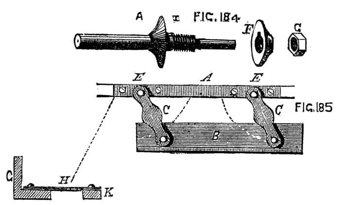
Fig. 184, 185.
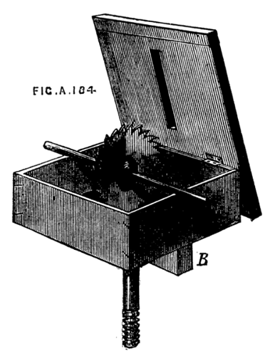
Fig. 184A.
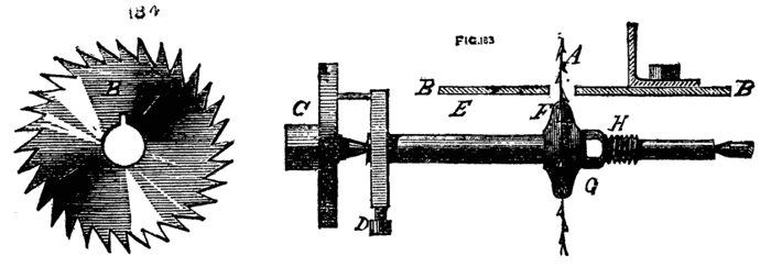
The method of mounting saws of small size, such as are suited to be worked by the treadle of a foot-lathe, is shown in Fig. 183. E is a steel spindle, of which the diameter equals that of the central hole in the saw B. At F, about the middle of the spindle, is a fixed flange, at the base of which is a short feather or inlaid key, X 184, which fits the small slot seen in the centre of the saw and reaches also within a similar slot in the movable flange, G, but it must not be so long as to come through to the back of the latter. This flange and nut H having been removed, the saw is slid upon the spindle till it rests against the fixed flange; the movable one is now to be brought against it and clamped by the nut. The spindle is sometimes made with a square end to fit the square hole chuck, and centred at the other, or it is drilled at both ends, so as to be driven by the carrier or driver chuck, C, D. It must be so placed as to run towards the operator. The above arrangement must now be made complete by the addition of a platform, B, on which to lay the work that is to be sawn, and on which some contrivance can be adjusted to guide the passage of the saw through the same, so as to cut the work in parallel pieces, or at any desired angle, such as would be necessary for mitred joints. For the general uses of the amateur a mahogany or hardwood platform is as good as any, and such as is delineated in vol. ii. of Holtzapffel's valuable work is perhaps the best arrangement. The saw table rests on the opposite ends of a kind of open box, which is represented without the two sides, although they may be added if desired, and the whole when removed from the lathe would then form a case for the saws, or serve other similar purpose. The platform is hinged, so as to overlap, as seen in the Fig. 184A, and there is in the middle of it a slit cut by the saw itself, which, when it is mounted on its centres will be in the position shown. If sides are added a notch must be made in the upper edge of both for the passage of the spindle. The fillet B fits between the bearers of the lathe, securing the parallelism of the whole. When made with four sides the box must first be placed on the lathe bed and loosely held by the bolt beneath. The saw is then mounted, and the box adjusted to its place and fixed. The cover is then (if for the first time) brought carefully down upon the saw, and the lathe being put in motion the slit is made, and its position will be truly at right angles with the spindle and the lathe bed. Of course, in future operations the platform is lowered over the saw before the holding down bolt is permanently screwed up. The sides of the saw-kerf may be edged with brass if preferred, but on the whole the plan is not to be recommended, for if, as will occasionally happen, the saw should get slightly out of truth, or vibrate a little when in use, the teeth will come into contact with the metal and be blunted or broken. If the saw-kerf by constant wear should widen too much, the whole platform is renewable at little cost, or a new piece can be let in, and a fresh saw-kerf made. There are several guides for parallel work. The one shown in Fig. 185 is precisely such as is to be seen in the ordinary parallel ruler—A is the back bar screwed to the platform at the right-hand edge; B the guide or fence which, when the connecting links C, C are perpendicular to A, should touch the saw; D, D are arcs of circles of which E, E are the centres. They may be arcs of brass pivoted to the links and passing through a slot in the bar, A, A, or may themselves be cut as mortises in the platform, in which fit a pair of bolts with thumb-nuts passing through the links, by which to clamp the fence in any desired position. This form of parallel guide is not very substantial, and is not correct in practice unless the pins are very nicely fitted, and the links precisely of a length. The second figure shows the sectional form of the fence G, the links being represented at H, and the fixed bar at K. The following is a more solid and unyielding guide, and much to be preferred. Holtzapffel attributes it to Professor Willis. It is merely a modification of the T-square as used with the ordinary drawing board with an arrangement for fixing it in the required position. The present arrangement differs from that in Holtzapffel's work in the manner of fixing it and the addition of a second T-piece on the side next the workman. In Fig. 186 A is the upright part of the fence, B the bottom or sole, to which is attached at each end the T or cross pieces, E, E, which slide along the straight edges of the platform and secure the constant parallelism of the fence to the surface of the saw; C is the groove or slot, in which a screw, D, traverses, and the fence is thus fixed by a turn of the thumb-nut, D. This fence can by no possibility get out of truth; it is easily removed by taking out the single screw, and it is far more simple and more easily made than the one previously described. The nearest edge of the platform may be marked in inches and eighths, and the fence can then be instantaneously adjusted for sawing pieces of any desired width. It is not always, however, that straight, rectangular, or parallel strips are required, and an additional arrangement is needed to form a guide for sawing angular pieces. Now it is not sufficient to lay the guide fence at a given angle, for if the latter were arranged for that adjustment by taking off the tees and causing it to turn upon the screw which secures it in place, and a piece of board were placed against it to be sawn, the latter would press against the saw sideways as seen in Fig. 187. The guide fence for angles must itself therefore travel in a line parallel to the saw and carry with it the piece to be cut. The simplest and usual arrangement is that given in Holtzapffel's work. A dovetailed groove in the platform running in a direction parallel with the saw carries a sector attached to a bar which fits the groove, and this bar is free to move forward or backward without lateral movement. The piece to be sawn is thus rested against the fence forming the straight face of the sector, and the whole is moved forward together against the edge of the saw. Fig. 188 explains this. It will be seen that several grooves are made side by side, all of which fit the slide alike, and by moving the latter into either of these a lateral adjustment is effected to suit pieces of different widths. The sliding strip should be made of hard wood and nicely fitted, and may be lubricated with soap, or polished with black lead, either of which will cause it to slide with diminished friction. Fig. 189 shows a somewhat different arrangement, by which more lateral adjustment may be given. The sector is replaced by a T-square, the blade of which has a slot through which a screw passes into the sliding bar. A second jointed rod is added, passing through a staple in the slide, and by a screw in the latter the T is fixed as required. The staple must turn on a centre to accommodate itself to all positions of the T-square, and a second eye may be placed on the opposite arm to allow the guide rod to be removed to that side, which is sometimes more convenient. The sector also may be made adjustable as in Fig. 190, and clamped by a simple screw in the slot. Either of the above methods will allow sufficient range for small work, such as is likely to be the object of amateurs or those who add small saws to the foot lathe. The guide for angular pieces may indeed be in many cases dispensed with by making use of patterns of wood chiefly in the form of triangles; these sliding against the parallel guide, and carrying the work with them, will answer well in a number of cases where other provision for such work has not been made in arranging the saw table. It must be remembered, however, that in this case the length of the piece (supposing it to be the side of a picture frame to be mitred) is limited to the space between the fence and the saw, which in the more perfect arrangement is an evil plainly avoided. It may sometimes be necessary to cut pieces with various angles not in the same plane. By using the hinged platform, and adding a screw attached to the front of the box, and standing perpendicularly, the front of the table can be raised to a given angle, but those who are likely to enter extensively into the cutting mathematical figures are referred to vol. ii. of Holtzapffel's work, where the subject is fully explained and illustrated. The following remarks upon the proper speed of saws and sizes of teeth are copied from that work, and may therefore be relied on:—
"The harder the wood the smaller and more upright should be the teeth, and the less the velocity of the saw.
"In cutting with the grain the teeth should be coarse and inclined, so as rather to remove shreds than sawdust.
"In cutting across the grain the teeth should be finer and more upright, and the velocity greater, so that each fibre may be cut by the passage of some few of the consecutive teeth rather than be torn asunder by the passage of one tooth only.
"For gummy or resinous woods and ivory, the saw teeth must be keen, and the speed comparatively slow, to avoid the dust becoming adhesive (by reason of the heat engendered by friction), and thus sticking to, and impeding the action of the saw."
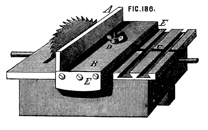
Fig. 186.
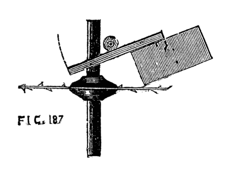
Fig. 187.
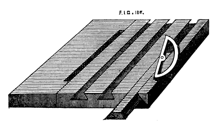
Fig. 188.
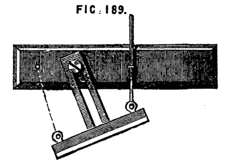
Fig. 189.
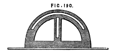
Fig. 190.
By raising the platform so as only to expose a small portion of the saw, it is easy to cut rebates, grooves for tongueing, and other work of a similar kind. The above arrangement of hinged table facilitates this application of the saw.
Fret Saws to Mount upon the Lathe Bed.
Convenient as the circular saw is when fitted as an adjunct to the lathe, its use is confined to pieces which are rectilineal. Curved lines cannot be cut by its means, and as it must frequently happen that portions of the proposed work are composed of arcs of various dimensions, it becomes necessary to provide the means of cutting them out. We may remark here, that although the circular saw, and that of which we are about to speak may be fitted to mount on the ordinary lathe bed; it is better for many reasons to have a separate stand, made like that of the lathe, but smaller, and fitted with crank, treadle, and flywheel, to serve for the various purposes of sawing, grinding, or polishing; the latter operations especially soiling and tending to damage the lathe. The above description of the methods of mounting circular saws will answer for a separate stand, as will the following details of saws for curvilinear work. In respect of the latter we have to provide for the perpendicular motion of the blade, which is necessarily thin and narrow, and also for stretching the blade so as effectually to prevent it from bending or buckling—guides are not required in general, as the work is moved about by hand in all directions according to the intricacies of pattern to be traced. For plain circular pieces, however, a very simple expedient is sometimes used, which will be described in its proper place, when treating of Bergeron's scie mecanique. The guides for parallel motion are various, and a selection may be made from the following Fig. 191. No. 1 is the arrangement used by Professor Willis, and detailed in Holtzapffel's work. A, A are wooden springs, one above, the other below the platform B. C is a guide pulley, D an eccentric. The catgut band which gives motion to the saw may be passed round this, or affixed to a metal ring as in the eccentric of a steam engine—or may be attached to a ring slipped over the pin of a crank disc, as shown at E. This pin being adjustable, permits the traverse of the saw to be regulated, which gives it perhaps an advantage over the first method. In the above the motion of the saw is not truly in a right line, but the deviation in so short a traverse is unimportant. The reader may, perhaps, imagine wooden springs a somewhat primitive expedient, but this is by no means the case, as they will retain their elasticity longer than metal ones when they are subjected to the rapid vibration which they are called upon to undergo. No. 2 is the parallel guide, used by Mr. Lund, and also described by Holtzapffel; the metal springs, however, shown by the latter being here replaced by india-rubber, which is now formed into springs of various sizes and powers suitable for our present and many similar purposes. A, A, and D, here form guide pulleys, the saw, E, being suspended from the first by the two catgut bands, on the ends of which are the india-rubber springs, F, F. The lower end of the saw is attached to another catgut band which passes over the pulley, D, and thence to the eccentric or crank disc as before. The platform is at B, B. Number 3 is an arrangement similar to the beam of Newcomen's engines. The arc at the end of the oscillating rod, and from the furthest point of which the saw is suspended, forms the guide for parallelism. Underneath the platform the pulley and eccentric may be used as before, and the saw is raised by the spring attached to the arc as shown. It will be evident on inspection that this arrangement is similar in principal to the last, as the arc forms part of a large wheel of which the centre is the point of oscillation. Watt's parallel motion, represented in the next diagram, is also suitable, the saw being attached to the centre of the short link—the springs being so contrived as to act upon the ends of the longer bars. With regard to the means of producing the necessary rapidity of movement, the above-described eccentric or crank disc can hardly be surpassed. In the saw patented lately by Mr. Cunningham, the disc is attached to the mandrel like a chuck, and the crank pin is connected to the oscillating rods that carry the saw by an intervening rod or link.
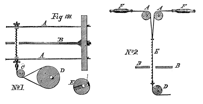
Fig. 191, no. 1 and 2.
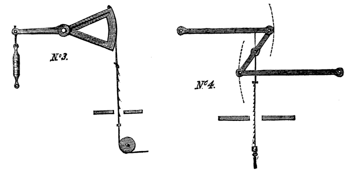
Fig. 191, no. 3 and 4.
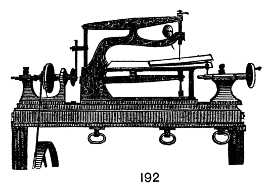
Fig. 192.
The whole is represented in Fig. 192, which is copied from the inventor's circular. There is a satisfactory parallel motion, and an india-rubber ball with a small tube attached is pressed at every stroke to blow away the sawdust. The whole plan and details are as good probably as can be devised, and as an addition to the lathe this saw is invaluable. Another form of mechanical saw to work with the foot, but without any flywheel, is figured by Bergeron, and is thence copied into Holtzapffel's book, and would therefore have been omitted here were it not that the price of Holtzapffel's work places it beyond the reach of many whom it is specially qualified to instruct; and that the former is in French and has not been translated. Therefore, as the arrangement of saw is exceedingly good, the writer has determined to introduce it here. Its construction is simple enough to be within the reach of any amateur in carpentry, and the only metal work required consists of a few iron rods screwed at the ends, such as the village blacksmith can readily supply. The saws are precisely those sold as turn or web-saw blades. It must be understood that the use of this tool is not the same as that to which fret or buhl saws are applied, but merely the cutting of boards in strips or curved pieces, such as the felloes of small wheels, circular plates to be finished in the lathe, as bread platters, or such other curvilinear works as the chair or pattern maker is accustomed to cut out with the several sizes of frame saws.
A, B, Fig. 193, is a stout bench with cross bar, C, underneath, cut away to allow of the movement of the treadle and its rod. On the top of the bench is a pillar, D, to support the spring bow E, by which after depression the saw is raised to its original position. F, F, and G, G, are guide rods (not continuous). The lower ones are fixed to the cross bar, c, and under side of the bench. The upper form the sides of a rectangular frame, H, H, of which the top and bottom bars of wood are dovetailed at the back to slide up and down the chamfered bar behind them, K. The frame thus allows of being raised or lowered, not only to suit work of various thicknesses, but also to act as a stop to prevent the saw from lifting the work as it ascends. The lower bar is extended on one side as in the figure, and is divided into inches, and on this graduated part is a slide with a point below, which can be fixed by a screw. This is, as the drawing plainly shows, intended for the guidance of the wood in cutting circular pieces. The saw is similar to the ordinary framed saw used by chair makers, but has two blades, and one central stretcher. The saw for curved work is narrow, that for straight cutting is broader. Near the latter a parallel guide is fixed, as described when treating of circular saws. This simple contrivance, although planned so many years ago, is of great value, and deserves to be far more generally known. To the joiner and cabinet-maker it would form a most useful addition to the usual tools of the workshop.
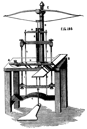
Fig. 193.
Akin to the circular saw are the various revolving cutters used either for the purpose of ornamentation or for grinding, such as circular files for flat surfaces, in which the teeth are cut upon the face or tool-cutters of particular sections for cutting the teeth of wheels, in the manner already described, to which may perhaps be added milling and embossing tools, although the action of the latter is rather that of a revolving die by which the work is stamped or indented with the pattern formed upon the edge of the cutter. The small grindstones and emery laps belong also to this section, as their action results from the abrasion of the material by means of the combined cutting power of innumerable small points or miniature teeth formed by the particles of emery or other material attached to the surface of the laps.
Most of the steel cutters may be made by the amateur, the metal being turned to the required shape and the teeth cut by small files or punches while the material is in a soft state. The little discs are then hardened and mounted, by a central hole previously made, on suitable spindles, the latter being either attached at one end to the mandrel as arbor chucks, or centred at both ends and driven like miniature circular saws. The ornamental cutters for embossing, Fig. 193B, A and B, are turned to the form of short cylinders, and the patterns cut by punches. These and the milling tools are mounted alike, Fig. 194. The rest is placed a short distance from the work, and the tool revolves against it. Some pressure is necessary to imprint the design, and this is easily obtained if the cutter wheel is placed so as to attack the work below the axis; the rest then becomes a fulcrum, and the shank and handle of the tool acting as the long arm of a lever supply the required force with little exertion on the part of the operator. In this way the milling is done on the edges of screw heads, and the embossed patterns on soft wood boxes. It is not easy to understand how the patterns in these cases are produced clearly without one part cutting into and effacing another, unless the size of the work is exactly a multiple of that of the tool. The error is plain if the work is stopped exactly at the end of the first turn, but in successive revolutions this error becomes gradually obliterated, and the pattern is eventually impressed clear and well defined. The same shank is arranged for different patterns of wheel-cutters, as the pin which forms the central axis is readily withdrawn and is made to suit the holes in several sets of discs.
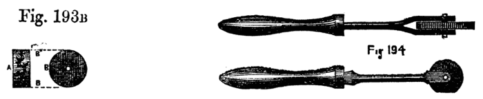
Fig. 193B, 194.
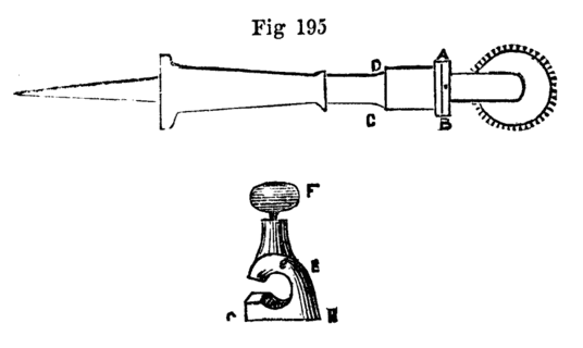
Fig. 195.
By the aid of the above simple tool a neat finish is readily given to many small works in wood and metal. A modification of the beading tools is here shown very similar to the screwing guide already given, but made with figured instead of sharp-cutting edge. This was communicated to the English Mechanic, Nov. 2, 1866. E, 195, is the guide which is placed on the handle A, B, C, D, and fixed by screw F. The mark i, on the guide, is placed against the rim, A, B, which is graduated and numbered. Each figure, as it is brought up and placed opposite i, will cut a different pattern when the guide is fixed. The tool must be held very firmly on the rest (the bottom of the guide G, H, being flat, is carried on the rest), the tool is advanced to the wood. The tool must be worked very steadily; but with a little practice, any amateur will soon use it perfectly, and produce many very pretty patterns. It is evident that provision is here made for placing the cutter at different angles to the work, by which means the circles of patterns may be traced spirally and in other positions varying from the ordinary one at right angles to the axis of the work.
The laps alluded to, which are to be mounted on spindles like the circular saw, are composed of wood and metal of determinate forms. First, there is the thin sheet-iron slitting wheel used by lapidaries, and which, when charged with emery, or sand and water, forms the nearest approach to the circular saw. It is, in fact, the circular saw of the stone worker, the ordinary saw used in their trade being a flat blade without teeth, stretched in a wooden frame and similarly fed with sharp sand and water in lieu of being made with teeth, the latter being replaced by the grittiness of the material. The circular plate of iron, brass, or lead alloyed with antimony, mounted on a spindle vertically, is used in a similar manner for grinding flat surfaces with the aid of emery, crocus, oilstone powder, and other substances, and the same is used edgewise for other work, as grinding and polishing tools, the section of the lap being such as will form the article required by reproduction of the revised plan of its own edge. Thus a lap running horizontally with a convex edge will produce the concave form required in beading tools, the latter, however, are more conveniently ground on brass cones mounted like the arbor chucks used for turning washers, rings, &c. The face of the tool or flat side is held towards the small end of the cone, and the latter is armed with flour emery. See Fig. 196.
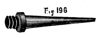
Fig. 196.
Before describing the eccentric and other compound chucks, a few examples will be given of the method of turning some of those forms in which the circle does not appear, where, in short, the boundaries of the figures are straight lines. It seems at first sight impossible to produce in the lathe by any simple means such solids as are formed from squares or triangles, of which the cube or die is the most common and most generally understood. This can, however, be accomplished, and a number of mathematical problems may be clearly demonstrated to the eye by such works skilfully made in the lathe. In this kind of work it is absolutely necessary to strive after perfection. In short, as Bergeron rightly says, the work imperfectly done is simply worth nothing at all; but when accomplished with exactness, nothing can be more worthy of a place in a cabinet of curiosities. The usual method of turning a cube is by shaping it out of a perfect sphere, but as the latter can hardly be made without a special slide rest made for the purpose, a method of turning the cube by hand alone will be given, the foundation of it being that which the lathe so readily produces, namely, a cylinder. By far the most proper material for the work in question is sound boxwood, and special care is to be taken to keep all angles as sharp as possible, and therefore to cut clean with sharp tools, and to avoid as far as possible the use of sand or glass paper. Fig. 197 shows a square described in a circle. The non-mathematical reader may be told to draw through the centre two diameters at right angles to each other, and to complete the square, as in the figure, by joining the extremities. The largest square that is possible to be drawn in the circle is thus described. This square will form one face of the cube, and the diameter of the piece of wood must be regulated according to the proposed size of the finished work. It is evident that this diameter is equal to the line drawn from corner to corner called the diagonal of the square. Now, in turning a ball or sphere, a cylinder would be turned of the exact length of A, C, because every measurement taken on a diameter of the sphere would be of that length. In the present case, however, the cylinder must be of the same length as the line A, B. Turn, therefore, with great care a cylinder of any desired size, gauging it carefully with the callipers and squaring off the ends truly. On one end, in which the centre point just remains visible, draw diameters and construct the figure 197. Turn out a chuck to fit it exactly, and let the bottom of this chuck be truly square. Take the precise length of the line A, B, with finely pointed compasses that can be fixed with a screw, and measure off the same, and mark it on the side of the cylinder. When the figure is placed on the chuck, a mark must be traced round it at this point, A, B, Fig. 198, and this must remain to the end. It may be made with a hard pencil or steel scriber, and, though distinct, must be very fine. It is at this line the wood will have to be cut off, but in this operation keep beyond it so as not to erase it. While the piece is in the chuck, rule lines, as E, G, from the points C, D, E, F, 198. Bisect also the length of the cylinder by the line, H, K, also finely drawn. Draw two more diameters, as shown by the dotted lines bisecting the sides of the cylinder, which is now divided round its circumference into eight equal parts. The lines, E, G, &c., can be ruled along the edge of the rest, or, if the latter is untrue, the cylinder may be laid on a plane surface, and a scribing block, or gauge, Fig. 199, may be drawn across it, or, lastly, a small steel square may be used; one part being carefully placed on the lines at the end of the piece in succession, the other part will lie evenly along the side, and will form a ruler by which to work. A division plate on the lathe pulley will facilitate the above measurements, but they can be readily made without it, and once carefully marked, all the guides required for cutting out the cube will be complete, and the work can be proceeded with, with confidence and decision. Proceed, therefore, to cut off the piece at A, B, with a parting tool, but with the precaution already named of not erasing the line by so doing. Now prepare a chuck which will take the piece lengthwise, Fig. 1992, and insert it in that position to the depth of the diameter so as to hold it securely, and the central line will show whether it lies evenly (which is, in fact, the use of this line). If even, a point-tool held on this line will form a mere dot upon it; if uneven, it will make a circle as it revolves. Place the rest across the face of the work, and, beginning at the centre, cut carefully towards the outside until you have cut away the wood as far as the line, A, B. You will thus complete one face of the cube, and an inspection of the end of the piece, shown black in the sketch to show the quantity removed, will prove that you thus produce a right line, C, D. Take out the work, and reverse it, and operate similarly on the opposite face; but in every case do not quite obliterate the lines first marked as guides. You have now a piece shaped like Fig. 200, A and B, and must make a smaller chuck to hold it; you have then to cut away in a similar manner the remaining parts of the cylindrical portion, and the cube will be complete. To finish the sides more neatly, lay upon the table the finest sand paper, and tack it at the corners, and with gentle movements work down precisely to the guide lines. This requires extreme care, for if once the piece is but in the slightest degree tilted up, an angle will lose its sharpness, and the beauty of the work will be marred. Hence we recommend to cut with sharp tools, instead of trusting to the finishing process. To cut, however, exactly to the line is very delicate work, and to the less practised hand the use of the sand paper on the faces in succession may be the necessary expedient. The main secret of sharp edges in works of wood and metal is to finish with hard substances, as emery stick or glass paper glued to a piece of wood, or the same nailed on the bench, and to try always to work on the centre, leaving the edges or angles to take care of themselves. When the reader has made a cube, as above, that will bear delicate measurement, he will be more than usually gratified, and will be qualified for still more difficult work. A chuck figured by Bergeron, Fig. 201, is very convenient, as it holds the work truly central; the jaws work simultaneously by a right and left-handed screw as in the die chuck. It is, however, perfectly easy to do good work without it, but the chucks should be carefully made, turned very flat at the bottom, with side truly perpendicular. A little extra care bestowed upon chucks will save many disappointments, and conduce to good work. The formation of a four-sided solid, consisting of triangles solely, in the lathe is a work of difficulty, owing to the impossibility of fixing the work satisfactorily in an ordinary chuck. The natural way to form such a solid is to turn a cone A, B, Fig. 202, and on its base to mark a triangle of the required size. It is then necessary to place the cone in a chuck, so that the ends of one of the lines thus marked and the apex of the cone are precisely level with the surface of the chuck, as shown in Fig. 203. But it is evident that adequate support is not thus obtainable. The apex of the cone cannot, in point of fact, be inside the chuck at all, as it is necessary to cut clean to its extremity, and even the base of the cone is imperfectly held at two points. Hence it becomes necessary to make use of "turner's cement," and to imbed the work fairly in it, while both are warm, to such a depth as will hold it securely and still allow the guide lines to be seen. The latter should be carried from the three angles of the triangle marked on the base to the apex. On the whole, this is the easiest method of fixing such work in the lathe; and if the piece is itself warmed before being placed, there will be time to adjust it precisely before the cement is cold. To do this, place the rest parallel to the lathe bed, hold a pointed tool steadily upon it, and note whether, as the work slowly revolves, the three points in question, viz., the two angles of the triangle and the top of the cone, are in one plane. When they are so placed, the rest is turned to face the work, and the material is carefully cut away till the gauge lines are just reached.[14] A pyramidical solid with a square base may be similarly turned. The following is the method of preparing the above turner's cement:—Burgundy pitch, 2 lb.; yellow wax, 2 oz. Melt together in a pipkin, and stir in 2 lb. of Spanish white. When the whole is well mixed, pour it out on a marble slab and roll it into sticks. Fine brickdust, whiteing, or any similar substance finely pulverised, will answer equally well to add to the pitch and beeswax. This cement is very useful, as it will hold the work firm enough to turn carefully, and nevertheless a slight blow will loosen it. To clean it off, warm or dip the work in hot water and wipe quickly with a piece of cloth. The above is from the "Handbook of Turning," the author of which has copied from Bergeron both the recipes given in his work; the one here described is stated to be specially serviceable in cold weather. It is perhaps rather less brittle than the first of Bergeron's, and for this cause is the best for general use. Holtzapffel sells this at one shilling the stick, which is of convenient size and generally of excellent quality. Bergeron gives a method of turning pilasters or balustrades, which is of great ingenuity, and applicable to work of various sections. The rectangular and triangular sections illustrated are not, indeed, strictly rectilineal figures, as the sides of the balustrades thus formed are not flat but rounded surfaces; they are, however, sufficiently curious, and when well turned are interesting specimens of lathe work. Bergeron's description relates to the pole lathe, or to work mounted between two centres with a pulley cut on the work itself to receive the lathe cord. The ordinary method of mounting on a foot-lathe will, of course, be much better and the whole operation of more easy performance. Let it be required to turn a moulded pillar or balustrade of the section Fig. 204, viz., a triangle with slightly curved sides. A piece of wood of the requisite length is planed up accurately to a triangular form, or, as it generally happens that a set of such pilasters are required, a number of such pieces are prepared which must be accurately planed to the same size, for which purpose a gauge or template, Fig. 205, should be made use of. Six or eight of these, if not too large, may be operated upon at the same time; but as six pieces of two inches across each face require a cylinder of about eight inches diameter, the number must depend on height of centres. The larger the cylinder, however (which, in fact, forms a chuck), the more nearly will the sides of the finished work approach to plane surfaces, as they will form arcs of a larger circle. Let a cylinder, then, be turned of sound wood with a reduced part at one end so as to form a shoulder. Divide the circumference into twice as many equal parts as there are pieces to be turned, the divisions being equal to one of the sides of these pieces as measured in a cross section. These divisions are to mark the positions of the grooves or channels in which the triangular strips are destined to lie. Half the circumference will be so cut out, the alternate divisions being left. Thus, to turn four pieces, each two inches wide, a cylinder of sixteen inches will be required, affording four grooves two inches wide, and four intermediate pieces forming the partitions between the grooves. The latter must, by means of the saw and chisel or other tools, be made to receive the strips exactly, and the ends of the latter being carefully squared off, are to be made to rest against the plate C, Fig. 206, which is cut out and screwed against the shoulder, after the above-mentioned grooves have been cut. The whole are then secured by two rings, with screws. Probably the stoutest india-rubber rings now made would answer as well as the iron clamps in Bergeron's description. Lay the strips in their places, but as they are flat they will not form part of the cylindrical surface, but will lie lower, as Fig. 207, or higher, Fig. 208; the latter is the best, and the pieces may, for this cause, be cut out a trifle deeper than ultimately required and they may be planed down a little to remove the angles and assimilate them to the cylindrical surface. The whole may then be turned together so as to form a plain cylinder, the clamping rings, Fig. 209, being shifted when requisite. The whole is now to be formed into a balustrade, but as the proportions of the mouldings of such a large cylinder would not suit the small pieces, the hollows must be less deep, and the raised parts less prominent than they would ordinarily be made. The clamps are now to be loosened, and the pieces reinserted with another face upwards, the flange or plate against which their ends rest forming a gauge or stop to ensure their position, without which precaution the mouldings would not eventually meet at the angles. In cutting a fresh side the utmost care is requisite, for if the work on the original cylinder is cut by the tool, it will be impossible to restore it, and the work will be spoiled. In replacing the strips, let the finished part lie below, so as to come first in contact with the tool, by which the angle will be clean. Extra care is for this purpose required in cutting the last side. It appears to the writer that another precaution should be taken which Bergeron omits, namely, to arrange the mouldings so that certain parts are left of the original size of the wood, in order to retain a certain number of points of contact with the sides of the grooves, so that the strips shall not fall deeper into them than at first. The extremities of the strips should certainly not be left smaller than the central portion, or the pieces will rock on the latter while in process of being turned. The two ends, therefore, should be allowed to retain their original triangular form, forming base and capital of the pillar, or the pattern may be so planned that, after the extremities have been left as supports they may be cut off when the work is complete. Care must be taken, in working as above, to have the cylinders so large above the estimated size that the inner apices of the triangles do not nearly meet at the centre, else the whole chuck would be very weak and split into triangular strips. The lathe called a spoke-turning lathe would accomplish this kind of work in a far more easy and speedy manner. The balustrade would have to be made by hand as a pattern, and cast in metal, and any number could be produced precisely similar. The lathe in question is on the following principle:—The frame carrying the tool (a set of revolving gauges) is made to oscillate backwards and forwards to and from the piece to be operated on. This is accomplished by its having attached to it a roller or rubber working against the cast-iron pattern placed parallel to the work, and below or one side of it. The rubber and frame are kept against the pattern by a strong steel spring. The cutters also travel in a direction parallel to the axis of the piece. Hence any elevated part of the pattern causes the tool to recede from the work in a corresponding degree, and a hollow allows a nearer approach of the tool. Thus, as the tool is carried by a screw slowly from end to end of the work, it is made to advance and recede in exact correspondence with the form of the pattern. An immense deal of work is done in this way, such as balustrades, spokes of wheels, the long handles of the American felling axes, and similar irregular forms.
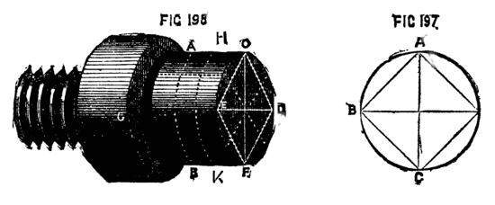
Figs. 197, 198.
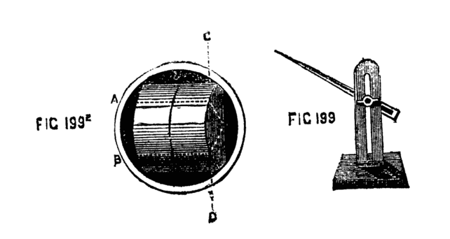
Figs. 1992, 199.
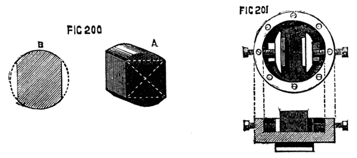
Figs. 200, 201.
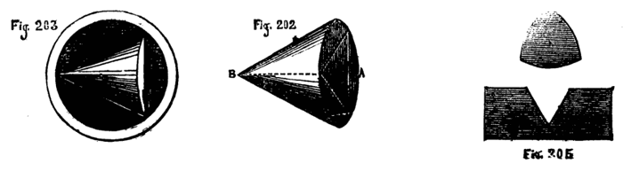
Figs. 202, 203, 205.
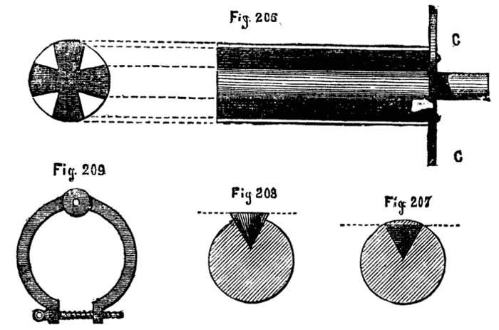
Figs. 206, 207, 208, 209.
The principle, indeed, is not new, as the rose engine is a similar tool, and, so long back as Bergeron's time, pattern plates were used giving any desired motion, endlong or otherwise, to the tool, or, which in effect is the same, to the work to be operated on.
Turning Spheres.
We must now recur to the sphere of which we have already spoken. The method previously given for producing it is not sufficiently accurate, although a very close approximation can thus be made to the perfect figure. It is probably impossible without special apparatus, rendering the tool independent of the hand, to turn out an absolutely correct sphere—indeed, it is a sufficiently delicate operation, even with the following or similar apparatus. For ordinary purposes, indeed, where the object is simply to produce a croquet ball, a spherical box, or a globe to be afterwards covered with paper, or any such work, the plan already given will generally suffice, and, indeed, is very extensively used. Some practised workmen, too, will, without even the aid of ruled lines, turn out spheres of average excellence by the eye alone, aided by a template. When, however, it is proposed to hollow out a sphere so as to leave a mere shell of ⅛ in. or less, and perhaps include a number of such shells one within the other, and a star in the centre of all, it evidently becomes necessary to work with greater accuracy, and still more so with respect to billiard balls, in which even the slight variation caused by increased temperature will seriously affect the result of the most skilful play, and cause the very best players to fail. The principle of the spherical rest is displayed by the diagram, Fig. 210.
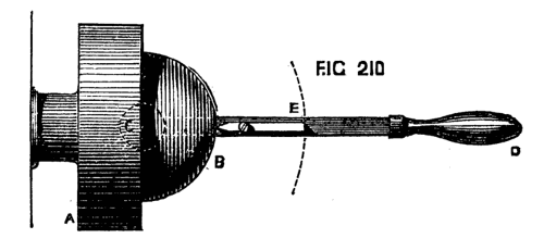
Fig. 210.
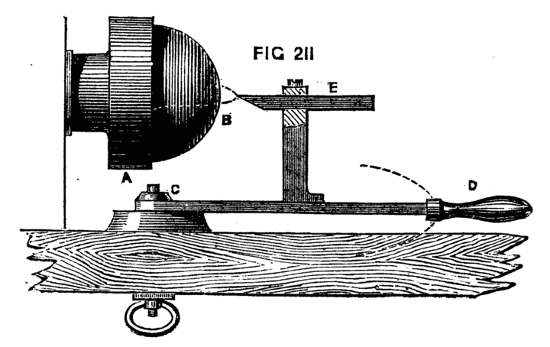
Fig. 211.
A is the chuck carrying the ball to be turned, of which C is the centre. In a right line with the latter, and below it, is a pin fixed to a block between the bearers of the lathe, and on this the arm, D, turns. The latter carries a tool-holder in which a pointed tool, E, is fixed. The point of this tool will evidently move in a circle, when the arm is moved by means of the handle, D; and, as the centre of the circle is exactly under that of the proposed sphere, the latter will be correctly shaped when the lathe is put in motion. Fig. 211 gives another view of the tool-holder. It is essential that the point of the tool should be in a line with the centre of the lathe mandrel, so that it shall act on a diametrical plane as it is carried round the work. Such is the principle upon which a practically useful tool for turning spheres has to be arranged.
The faults in the above simple machine are many. In the first place no provision is here made for the advance of the tool towards the work. In the second place the requisite firmness and stability cannot be obtained by merely causing the bar to revolve upon a centre-pin; and thirdly, as the tool post is fixed to the horizontal bar, the diameter of the ball must be limited. In point of fact, therefore, the above arrangement would not answer, and it is only described in order to illustrate the principle of all inventions for the production of spheres in the lathe. To give steadiness of action the pin forming the centre of motion is connected with a circular metal plate truly turned, upon which a second similar plate works, and to the latter is attached the tool-holding apparatus. It is difficult to make choice of a circular or spherical rest so as to give it precedence, since most of the patterns ordinarily made are good. To obtain the requisite movement is, indeed, by no means a matter of difficulty; and one or two adjustments in respect of the height and radius of the tool being provided, a very simple apparatus will answer the purpose. To commence with Bergeron's, which, though venerable, is by no means inefficient. This is represented in Figs. 212 and 213. A, B, is the base, the tenon, B, accurately fitted to slide between the bearers of the lathe, the whole being held down as usual by the bolt and nut, c. The top part of the base is surmounted by the accurately faced plate 214, on which a side sectional view is given in Fig. 215. This is fastened to the base plate (which, in Bergeron's description, is of wood) by four countersunk screws. It is turned with a recess, so that the outer part stands up in the form of a rim, and from its centre rises a conical pin, b, the upper part of which is first octagonal, and then rounded and tapped. It is this strong pin which forms the centre of motion, and it must stand with its axial line precisely in the centre of the lathe bed, so that if the plate were slipped close to the poppet head this line would bisect the nose of the mandrel. This is essential in all patterns of spherical slide rest. Upon the lower circular plate rests that represented in Fig. 216, A and B, the latter being the sectional representation. This plate is drilled in the lathe with a central hole, the lower part conical to fit the pin in the base plate, the upper part countersunk as in the figure, to receive the octagonal part of the pin and the nut. The projections a, and b, in B, represent the projecting rim, a, in the Fig. 216, A, and this is made to fit very nicely within the rim of the lower plate, while the adjacent part, c, rests upon the rim itself. The accuracy of these bearing surfaces is of the utmost importance, It is evident that this arrangement is calculated to give great stability during the revolution of the upper part of the rest, which is fixed securely to the plate last named. This plate has a hollowed edge cut with a set of fine teeth to be acted on by the tangent, screw D, Figs. 212, 213, and shown in Fig. 217 on a larger scale. The bearings of this screw are attached to the base plate, and the screw is prevented from moving endwise by collars as usual.
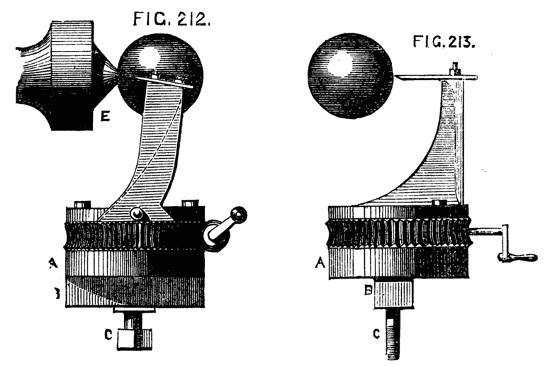
Figs. 212, 213.
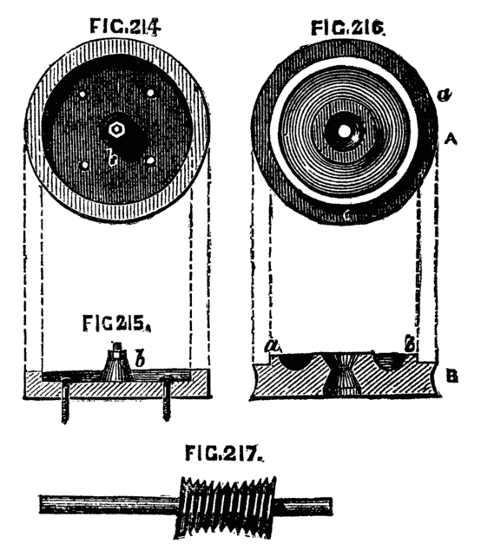
Figs. 214, 215, 216, 217.
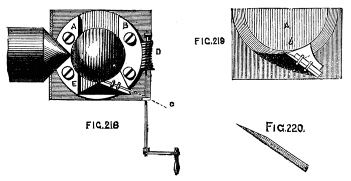
Figs. 218, 219, 220.
On the upper surface of the top plate are fixed parallel bars chamfered beneath like those of a slide rest, and between these the tool holder slides, the advance of the latter being effected by a screw precisely as in the slide rest already described. In the plan of this instrument, as seen from above, Fig. 218, A, B, are the bars. The tool is seen in position at C, the tangent at D. A scale is attached to the sliding part of the tool holder for determining the size of the sphere. The tool is again seen in position in 219, and detached in 220. In Bergeron's description of the above spherical slide rest the method of using the apparatus is thus described:—"Commence by placing in a chuck a cylinder of some sound wood, and reduce it to a convenient diameter, which should be a little greater than that of the proposed ball. With the gouge work down this, and give it roughly the form of a ball attached to a cylindrical base." This base serves to sustain the ball during the operation, and the form of an inclined plane is to be given to it where it is attached to the ball, as seen in the drawing, to facilitate the passage of the tool. After this preliminary work, place the instrument on the lathe bed, and cause the tool holder to advance by means of a screw (the one attached to the lower slide, not the tangent screw) until, reckoning from 0in., the starting point, the index attached to the sliding part has travelled over the graduated divisions of the scale, so as to denote the size of the ball in its present rough state. Then slide the instrument along the lathe bed, until the tool, accurately adjusted as to height, just touches the ball at the quarter circle. This will be better understood by the diagram Fig. 221, in which A, B, are the lathe bearers; C, the tool in position; D, the ball; E, the chuck or the base of the cylinder. Having previously determined the size of the finished ball, the work may now be carefully begun by clamping the rest underneath the bed, and making use of the tangent screw. Little by little the work is to be reduced, taking care not to cut too near the base on which the ball is yet carried. This base is to be cut away little by little as the tool comes round, and at the last cut the ball will drop off finished, and it is not to be further touched with sand paper or other material. Hence, as it approaches the finish, the tool must be delicately and steadily made to traverse, so as to leave a finished surface as it advances. Bergeron adds certain precautions as follows:—"If the material is very rough from the gouge, so that at any point the tool is likely to meet with such resistance as would endanger the work, such part may be pared down again by using the machine as a common rest for gouge or chisel; for the apparatus once arranged should not be altered nor the fixed tool shifted until the work is done. The tool throughout is to be advanced very gently forward at each turn by means of the screw, which causes the parallel movement, and the tool is to be accurately adjusted so as to be exactly in a line with the centre of the mandrel; it is also to be very keenly sharpened, and even polished." The first impression given by an inspection of the above figures is that the ball would be liable to drop off before it could be fairly severed by the tool. The writer determined to test this objection personally. He selected a piece of sycamore, which is very fit for the purpose, and useful as a kind of medium between hard and soft woods. A ball was turned by hand from this material having a diameter of about two inches. The neck by which it was held was retained of the size of a cedar pencil during the final shaping of the rest of the ball. It was of course not thus reduced until the ball was nearly spherical. Gradually the neck was cut away until it was perhaps as small as the lead of a pencil, yet still the ball retained its position, and the final stroke cut it off truly and tolerably cleanly, E, 212 and 213. It is really astonishing how small a portion of sound wood will retain a ball so turned, but the lathe should not be allowed to stop, else the tendency to hang down or sag would overcome the sustaining power of the fibres. Bergeron states, indeed, plainly, that the process answers satisfactorily, and as a man of large experience his opinion is certainly reliable. Nevertheless, since sand papering or after process is to be eschewed, it does appear to the writer that the final cut would leave a minute portion untouched requiring to be afterwards removed. Not having one of the rests in question the writer's opinion is to be taken quantum valeat. The spherical rest more commonly used is that represented in the "Handbook of Turning," since it is necessary not only that the machine should be efficient for turning a sphere, but likewise applicable to the ornamentation of the same by the revolving cutter and other apparatus used in such processes. This and some other forms will presently be described, and also an ingenious adaptation of the ordinary slide rest by means of guide pieces or templets to work of this character. A very good form of chuck for holding spheres during the operation of hollowing them out or forming stars or cubes within them will, however, be first introduced here as described by Bergeron. It will be at once seen how simply and efficiently a ball can be thus held during such processes.
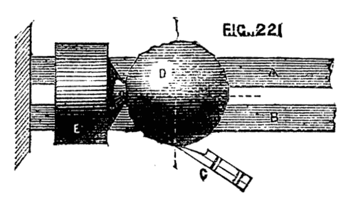
Fig. 221.
Fig. 222 represents a chuck for holding balls, A being a sectional view, B an elevation. In the first, b, b, represents the body of the chuck, made as usual to screw on the mandrel. At a, the chuck is formed with a shoulder like an ordinary box. This part of the chuck is to be hollowed out to fit the ball on which it is intended to operate. On the side of the chuck at b, is to be cut a screw of medium pitch. Mounting another piece of wood in the lathe a kind of cover, c, c, is now to be made to fit over the body of the chuck like the cover of a box, but hollowed out to the curvature of the ball. A ring of brass or wood of section D being screwed on the inside to the pitch of the male screw on the outside of the chuck will hold the three separate parts of the apparatus firmly together. Let them be thus arranged and finished as one piece on the mandrel. Afterwards drill a hole in the centre of the part which forms the cover, and enlarge it so that its diameter shall slightly exceed that of the openings necessary to be made in the ball for the purpose of hollowing out and forming within it stars, or lesser spheres, box, cube, or other design, at pleasure. In this chuck the ball will be held not only centrally but securely. It is of course necessary to have a chuck specially made for each different sized ball, but when it is considered that such things as these are merely turned as curiosities and to prove the capabilities of the workman, it is not probable that more than two or three sizes of chuck will be needed, and the difficulty of making them is not great nor the necessary expenditure of time, either. They should be made entirely of sound boxwood, and so arranged as to the size of the respective parts that when the ball is inserted and the cover placed on, the latter shall not quite reach the shoulder on the base of the chuck. In the spherical rest of more modern times the principle of that already described is almost necessarily retained. It is figured in 223. The sole A is formed like that of an ordinary hand rest, so that it can be advanced across the lathe bed, and secured by the nut and screw underneath as usual. From this rises a central circular plate, which need not be more than a quarter of an inch thick, but turned truly flat, that it may be parallel with the surface of the lathe bed. From this rises the conical central pin upon which works the plate B, the edge of which is racked to be moved by the tangent screw C. Across this circular plate is securely fixed the chamfered frame D surmounted by the part E which carries the socket and tool receptacle, the details of which will be entered into when describing the rest for ornamental work.[15]
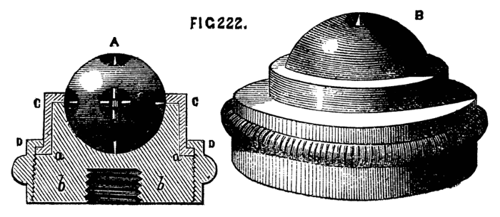
Fig. 222.
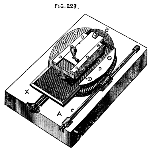
Fig. 223.
The method of turning from a pattern acting on the tool has been alluded to. In some cases a similar method is pursued, in which the hand supplies the place of automatic machinery, an instance of this is the application of pattern plates or templets to the small slide rest now to be described, by which not only parallel or spherical work may be done, but the elevations and hollows in moulded work may be followed without difficulty. The pattern plates can be made by the amateur or workman so that not only is no extra cost incurred, but any desired form can be given to the work and as many duplicates made as may be requisite. The simple slide rest itself is represented in Fig. 224. The lower iron or steel frame is rectangular, chamfered underneath, and is cast with a projecting part B underneath to the socket of the hand rest. There is, therefore, no sole or saddle required, and the height is adjustable at pleasure to suit 3, 4 or 5-inch centres. C is a plate of brass, cast with one V-piece similar to D, the second E being removable at pleasure, or both V-pieces or guide bars may be attached by screws. They are attached by two or three screws passing through oval holes in the plate and tapped into the bar, so that a little play to or fro is allowed, by which they can be adjusted to grasp with more or less friction the iron bevelled frame. They are kept up to their places by a pair of large headed screws tapped into the edge of the brass plate and marked e, e, in the drawing of the rest. On the top of the brass plate is fixed in a like manner another pair of chamfered bars similar to those of a slide rest for metal, but in the ornamental turning slide rests, where lightness and accuracy are more needed than strength, the parts are proportionally smaller. The frame, for example, may be six inches or six and a half inches in length by two in width, the brass plate two inches square, or perhaps two and a half by two, the longest measurement in the direction of the upper guide bars, between which the tool receptacle will slide. This will be quite large enough for a five-inch lathe, although the measurement may be more or less if desired. If taken as above, the iron frame may be half an inch deep and the face of each side of similar size, leaving one inch between, in which the screw will lie. 224 B shows the under side of the frame with a cross piece to which the part, B 224, is attached. The guide bars for the tool receptacle may be similarly small and light. If the plate is ¼ in. thick and two in width the bars may be ⅜ in. stuff before being bevelled, the attaching screws can then be ⅓ in. or 3/16 in. in the shank, the heads being large and flat, and not countersunk. It is probable that many amateurs would like to attempt such a rest themselves, hence we have given the above details. We must however, warn them that as the above is for ornamental turning, where accuracy is of the utmost importance, great care must be exercised in the work, and the various parts must be fitted to the utmost perfection. The upper face of the lower frame must be quite level, and the sides quite parallel, and the upper or cross slide must be fitted precisely at right angles to it. Above all, the screw by which the upper part is advanced in either direction requires great precision. It should be made with a fine thread deeply cut, and must fit its nut under the brass plate, D, without shake. The nut itself should be long, and must be carefully bored and tapped; it should be also sawn through its length underneath, to give it a spring, so that it may grasp the screw tightly yet easily, and this will also compensate for wear. This will be understood when it is stated that the milled head by which the screw can be turned is graduated round its circumference, as is also the face of the bed or lower frame of the rest. Hence to give the head a turn, or half, or a quarter turn, must draw the sliding plate exactly the same distance to or fro, at whatever part of the frame it may be at the time. This necessitates all the threads being precisely alike. [We say precisely with a certain mental reservation, for, strictly speaking, perfection is hardly possible, and the skill and science brought to bear upon screw cutting when perfect work has been necessary, as for astronomical instruments, would hardly be credited, so extremely difficult is this part of the mechanical art.] It would be better for the amateur to get the screw and nut cut by Holtzapffel, Munro, or other first-class maker, who has the requisite means and can command the highest skill. Between the upper guide bars are fitted various tool receptacles. The only one which need as yet be spoken of is that which holds the little inch-long tools for ordinary work or for use with the eccentric chuck. This consists of a brass plate bevelled to fit the chamfered bars, on the end of which is a small piece of steel with a rectangular hole and set screw, as seen in the drawing marked X. This plate has a tailpiece of rather thicker metal, through which pass two set screws, which regulate the depth of the cut to be made, their points bearing against the end of the brass plate on which this tool receptacle works. No screw is attached to move this upper slide, but a wooden handle projects from it at right angles to be moved by hand, or a lever Y is made use of. This has two projecting pins, the front one taking one of the holes, 1, 2, 3 of the slide, the other one of a set of similar holes in the top of the chamfered bars. By this the slide can be advanced with ease and great steadiness. We now come to the pattern plates or templets F, alluded to. These are formed of sheet iron about 1/20 in. to 1/16 in. thick, and must be long enough to reach from one end to the other of the iron frame A, underneath which at each end are two holes a, a., Fig. 224 B, to receive screws by which the templets are attached by means of the slots, b, b. The outer edge, a, of templet is the pattern to be copied. The dotted lines in Fig. 224 show a plate in position. The tailpiece of the tool holder to be used has a projecting stud, or is made with a screw with or without the roller seen at H, and this is kept in contact with the templet by the hand or by a spring, so that when the slide traverses the lower frame the tool-holder necessarily follows all the curves of the pattern plate. An inspection of K will make it evident that the projecting screw must be so regulated as to length as to allow the tool-holder to go to the extremes of the projections and hollows. It must therefore in the pattern shown be at least as long as the line a, b, Fig. K, and a tool-holder of sufficient length must for similar reasons be selected, or the tailpiece might touch the fixed plate on which it works before the guide pin had penetrated the deepest hollow of the pattern. With these precautions nothing can exceed the ease with which this clever adaptation of the slide rest is made and used, the greatest advantage being that the workman can make his own templets to any curve or series of curves that may be desired.
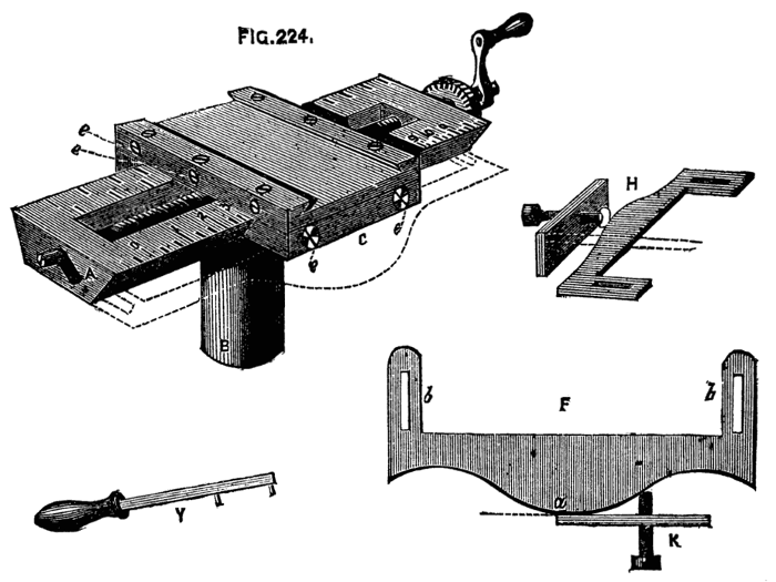
Fig. 224.
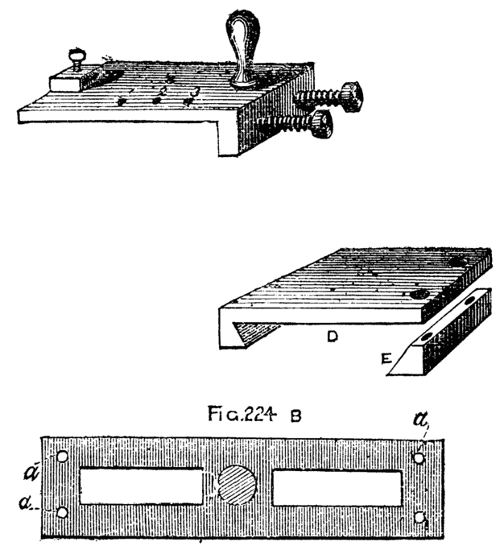
Fig. 224B.
At a later page is described a slide rest with the arrangements of the tool-holder somewhat improved, and calculated for the reception of larger tools and apparatus. The little rest here described is, however, very light and useful.
Hoblyn's Compound Slide-Rest.
A compound spherical slide-rest, for ornamental turning lathes, which has been patented by Mr. Hoblyn, Rickling-green, Essex, is capable of turning and ornamenting accurately spheres and any segments of circles convex or concave, either on the surface or cylinder; also, it is stated that by the addition of templates any other curves, not segments of circles, can be turned out, in addition to the work performed by an ordinary compound slide-rest. In our illustrations, Fig. 1 is a side view, and Fig. 2, an elevation of the rest. A is the lower, and B the top plate, C the carriage, and the saddle as usual. The lower plate, of iron, is planed on bottom and sides, and has a longitudinal bevelled slot in the bottom to receive the fastening bolt, so that the plate can be tightened up at any point on the lathe bed. At one end of this bottom plate is a piece raised the whole of its breadth, accurately turned and faced, with a stout turned pin, b, for a pivot in the centre. A wheel, c, is placed around this raised piece, having any specified number of cogs, and on its top any specified number of small holes drilled to receive two pins as segment stops. The top plate is slightly narrower than the bottom one, and has on its underside a corresponding surface to that raised on the plate A, turned and faced with countersunk hole in the centre to fit on the pivot b, on which it is tightened by a screw and washer. The top of B is placed to receive two parallel bars of brass, bevelled on the inner edge, so as to form sliding bars for the carriage C, one bar being a fixture, the other capable of adjustment by tightening screws. The sides are also accurately planed, and on one a tangent screw, e, is so fixed as to be put in and out of gear with the brass wheel, c, for the purpose of driving the top plate round the pivot b. In the raised surface of B, is a countersunk slot forming a quarter circle, with screw passing through it into the bottom plate; by this means the top plate can be firmly fixed at any angle to the bottom plate for the purpose of slide-rest turning. A small pointer, f, works clear of the brass wheel in the capacity of segment stop—two small pins being placed in the specified number of holes in c. On the opposite side of the screw, e, on the top surface, a screw, g, works in two standards screwed into the plate through slots in the bar, which works through a traveller, h, firmly attached to the carriage, C, and therefore capable of driving the carriage in a rectilinear direction—for slide-rest purposes. This carriage, C, consists of an iron plate i, with standard k, top plate l, with parallel brass bars to receive tool receptacle m, the bottom plate and standard being in one piece with the plate, planed side and bottom, so as to slide truly between the parallel bar on B. The standard has its surface accurately turned with a pin in centre to form pivot. The top plate is planed true, bottom, sides, and top, and has a countersunk hole in the exact centre, so as to work on the pin, and tightens up with a large nut. In the plate is a countersunk slot forming a quarter-circle, with screw passing through into the standard, to set the tool receptacle either parallel with B for spherical turning, at right angles to B for slide turning, or at any angle for thick and thin cuts, and similar patterns when used either as a spherical or slide rest. The parallel bars are to be similar to those on B, to enable the tool receptacle to be advanced or retired by screw or lever. This part of the machine can be adjusted for height of centre thus:—The standard k to be a hollow cylinder with fixing screw on one side; the plate i to be made with turned pin on bottom, to fit into standard; elevating screw; saddle as usual, but with the addition of a small hole drilled in one of the sides, and a corresponding one in the side of the lower plate A, so placed that when a pin is fixed into these holes the pivot is exactly central to the lathe centre.
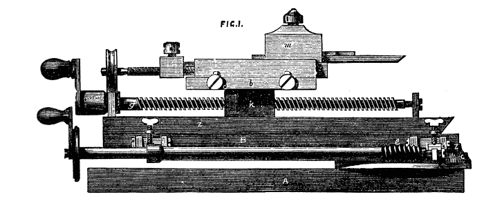
Fig. 1.
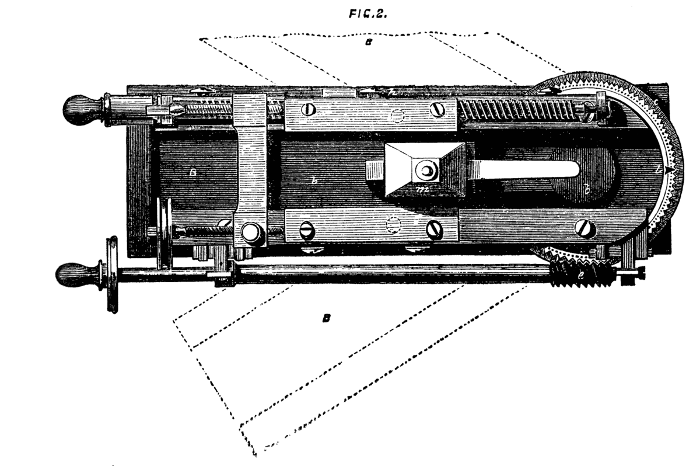
Fig. 2.
The way of using the spherical rest is thus described by Mr. Hoblyn:—"When altogether, and the point of tool adjusted by means of a square exactly over centre of pivot, it is evident, if the top plate moves round, the point of the tool will still be in the same place; but if we retire the point one half-inch, on moving the plate right round it would describe an inch circle, so that if the centre of pivot be exactly under the centre of the lathe, and we move the rest the half-circle, it will cut a perfect ball (or any part of one, if the cut be less than half a circle) of such size as the distance doubled of point of tool from centre of pivot. Therefore, by adjustment of the lower plate on the lathe bed according to the size of material (this, of course, does not allude to the act of turning a ball, when the centre of pivot must be exactly under centre of lathe), adjustment of carriage from centre according to the size of circle required, and adjustment of tool for depth of cut, we are enabled to turn any convex curve. To turn the concaves, instead of retiring from centre of pivot, it is only requisite to advance the point beyond the centre to the distance required, when the same rules apply as to the convex curves. In turning the concaves, however, it is necessary to turn the plates half-round, so that A and B are in the same straight line, instead of over each other. This enables you to work on any sized piece of wood, the object of the longitudinal slot in the lower plate being to enable you to adjust your previously arranged curve to any sized wood or ivory that your lathe will take, less 2 in., the height of machine. The desired curve having been turned, take out the chisel, and place in the receptacle any ornamenting instrument, drill, eccentric, &c.; advance the point till it touches the work, then set your screw for depth of cut, and work according to fancy. Whatever it is it must be mathematically correct on the curve, as you have not altered it in any way. You then remove your rest to cut the next desired curve, and proceed as before. The best way to execute a piece of work is first to make a sectional pattern of your design, either by drawing or cutting it out with scissors from a double piece of paper, when, of course, both sides come the same, the line where the paper is doubled being the line of centre of lathe. You can then, with a pair of compasses, ascertain with accuracy the necessary size of circle, and the position of centre of pivot to procure the desired curves. You may also produce a very good effect by a combination of two different curves in this way:—Let your ornamental instrument be the universal cutter; working horizontally follow up your curve with it, but, instead of cutting right out on your curve, let the instrument finish of itself in wood previously turned so as to fit its curve, when you get the lesser and greater curves following in unbroken succession. With the eccentric chuck numberless effects of the most curious description may be produced, even work supposed to be only possible with a rose engine. We believe the tool is to be seen at the shop of Mr. Evans, 104, Wardour-street.
To turn a sphere by means of a template attached to the slide rest as described, the following adjustment of the rest and mode of proceeding should be followed. A, B, Fig. 225, is the chuck containing the material, H, to be worked into a sphere. Upon this the length, or diameter (equal to that of the template, as will be explained), is to be marked at K, K, which being divided equally by the line L, L, will give the dimensions of the ball as if it were about to be turned by hand. The corners are to be turned off with the gouge, as far as shown, K being equal to e L, and K f equal to K e. The outline of the ball will with these measurements not be touched. The angles left may also carefully be removed, but (as shown by the figure) this operation must be conducted with great care. A template must now be made containing a full semicircle, every part of which can be traversed by the stud or screw upon the under part of the slide, or the ball will not be severed by the final cut. It is evident that the traverse of the slide during the operation will be the full radius of the ball, and in this, and indeed all cases of deep recesses, and greatly projecting mouldings, the ordinary tool-holder with tailpiece had better be removed, and replaced with a slide like M, having a pin straight through it to rest in contact with the template. This will preclude the necessity for the long stud or screw spoken of before as necessary when the slide with the tailpiece is used, but the tool cannot be advanced independently of the template as when the other form is used. Fix the rest so that when the top slide is at its central position the tool may stand as in the sketch exactly upon the central line of the ball. Take care that thus placed the tangent-pin of the slide is on the central mark of the template. The long frame of the rest must likewise be parallel with the bed of the lathe, keeping the top slide pressed against the template with the left hand, while the top part traverses the frame under the action of the screw moved by the right hand, the ball will be correctly cut.[16] One or two cautions must, however, be given here, to ensure a satisfactory result. In the first place the cylinder from which the ball is to be made must be exactly of the diameter of the semicircle on the template. H, H is the cylinder to be turned to a sphere, G, G, B shews the position of the tool at starting, the dot on A, the templet, the tangent pin of the slide, Fig. 226. As the work proceeds the tool will take the several positions shown, the dotted lines, D, being equal and parallel. The tool will thus repeat the form of the template. Let the latter remain as before, but let a smaller cylinder be inserted in the lathe, or, which is the same thing, let the tool be now lengthened so as to start at C on the inner dotted line. When the pin, F, has reached K, which should be the axis of the ball, the tool will be at M, quite out of cut. Fig. 227 represents three forms of tool in contact with the ball at two points. The first two will evidently be out of cut at the axial line, as the side of these bevels will then touch the piece to be turned. C is a form that will remain in contact from the diameter to the axial line. The left side of the edge is slightly overhanging the side line of the tool, D.
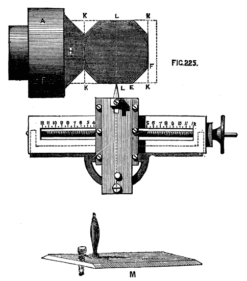
Fig. 225.
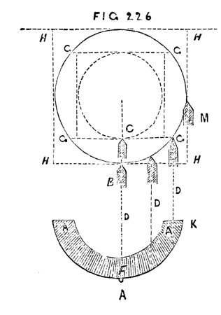
Fig. 226.
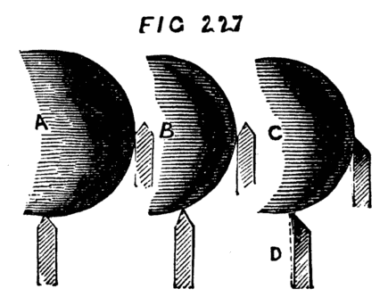
Fig. 227.
When the part shown has been cut this tool must be removed and a similar tool bevelled in the reverse direction, adjusted by reference to the central line of the ball as before.[17] It is recommended to roughly shape the work with the gouge, and partially to cut it off with the parting tool so as to relieve the tool as much as possible, and when the last finishing cut is to be taken a freshly sharpened tool is to be made use of. It is evident that in the above and similar work the rest may be placed across the end of the cylinder if preferred to turn the right hand hemisphere, but it would have to be moved for the second half, which should be avoided, if possible. The advantage which the circular rest has over the above is due to the fact that the tool and rest once in position, neither has to be readjusted until the work is complete. The slide rest and semicircular template forms, however, if judiciously used, a very serviceable substitute and makes very satisfactory work. Whether or no the reader has a complete rest for spherical work, he should decidedly provide templates to use as above. They are not only useful for turning or ornamenting spheres, but any forms whatever that may be desired, and they possess this special advantage, that when a dome or other pattern has been thus turned with a plain tool the same template used with revolving cutters will enable the work to be ornamented with perfect ease, doing away in a great measure with the need of a dome chuck. Suppose, again, that a number of pieces are desired precisely similar, as a set of pawns for a set of chessmen, a sectional drawing made and transferred to a piece of sheet-iron, and the latter cut to form a pattern plate, will enable the most unskilful to work satisfactorily. Nothing more need be said of the uses of templates, and for the present the subject will be dismissed, though it may possibly be referred to again in a future page.
Chucks with Slides and Compound Movements.
The first of the chucks comprised under the above head is the oval or elliptical chuck, and it is introduced first in order because it is not essentially a machine for ornamental turning, as are the eccentric and others of this class. There are many plain works required of elliptical section, as bradawl and other tool handles, for which a very simple arrangement is required.
The principle of the oval chuck is as follows:—There is an arrangement of slide, by which as the piece revolves it is drawn gradually further from the tool during half a revolution, and in a similar manner caused to approach it during the remaining half revolution, each point in the circumference alternately partaking of such movement; the whole of these points together, which, of course, form the circumference, will become an ellipse. Let D, Fig. 228, be the centre of the mandrel, A, B the direction of the slide moving up and down in a right line, and carrying the work upon a screw in the centre of it. C, E become centres, and may be taken as the extremes, for as the work revolves a succession of centres are formed and instantaneously changed. The figure produced will be the oval shown. To render this, however, clearer, Fig. 229 may be taken, which represents the chuck in its most simple form with separate details of the parts which compose it. A is the chuck with central slider and chamfered bars, as described in speaking of the slide and rest and previous apparatus; B is the slide detached; D, front view of the same. The short arms a, b, pass through slots in the back plate as seen at C, which shows this plate with slide removed. Through these short arms pass a pair of adjusting screws; or still better a and b are themselves cross arms or pallets extending the width of the plate as seen next drawing, and in the chuck of Muir which follows. They are merely flat plates of steel embracing the guide ring, so that some point in their inner surface may rest against it during every part of the revolution of the chuck.
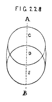
Fig. 228.
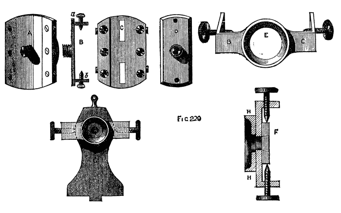
Fig. 229.
The guide ring here alluded to is shown at E, and also at G, fixed in its place upon the poppet. It is in the form of a raised ring with arms, B, C., which are turned at right angles near their ends, and through which pass adjusting screws with conical points. This plate is flat at the back and bears against the face of the poppet, the mandrel nose falling into the central opening E. It is kept in place by the points of the screws falling into conical holes at the sides of the poppet head. At F is a side sectional view of this plate, with its raised and accurately turned ring, H, and at G is seen the poppet with the plate attached, the left arm being dotted to show the position of the adjusting screw. It is this ring and plate which regulate the movement of the slider, and, with it, of the work, the latter being attached to the screw in the centre of the sliding plate, which screw is a counterpart of that upon the nose of the mandrel. Suppose the chuck A screwed to the mandrel, and the ring accurately concentric with the mandrel, in which position, the pallets must touch at two opposite points. In the best chucks there is an adjusting screw to each, by which the contact can be regulated. In this position any object of a circular form can be turned, for the slider remains in one position, and its screw, upon which the work is fixed, is a continuation of the mandrel. But if now the adjusting screws of the part E are turned, the one being loosened and the other tightened, the guide ring will no longer be concentric with the mandrel, and, as the screws of the slider bear upon it, the slider will during its revolution be moved to and fro to a distance regulated by the eccentricity of the guide ring. The combination of this circular motion of the chuck and rectilineal movement of the slider will produce an ellipse, and a stationary tool applied to the work will cut it, into that form.
The above simple arrangement of oval chuck suffices only for plain work. The only figures that can be described by its means, upon the cover of a box, for instance, being a series of ellipses of which the longest diameters fall in the same right line, and of which the centres are coincident with the axis of the mandrel, as Fig. 229.
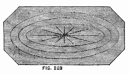
Fig. 229.
Even these, however, cannot be done without some compensating arrangement, as the minor axis does not diminish in length at the same rate as the major—hence the ellipses get narrower and narrower until the central one becomes a mere right line. This is referred to again in the ornamental section of this work.
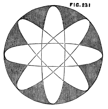
Fig. 231.
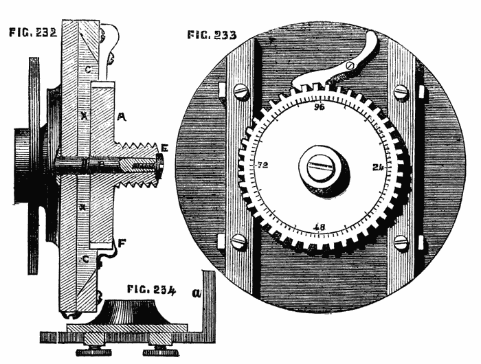
Figs. 232, 233, 234.
X
Combinations like 231, in which the ellipses intersect, cannot be so obtained. Hence the oval chuck is provided with a wheel, either racked to work by a tangent screw or fitted with a spring catch, by which it becomes a dividing plate. This wheel revolves on a central pin[18] fixed to the middle of the sliding plate, and carries a screw of the same pitch as that upon the mandrel to which other chucks can be attached. By this means the axial lines of the ellipse can be varied in direction. This addition is shown in Fig. 232, which is a section, and 233, which is a front view. In the former, A is the wheel, which, as previously explained, should be so arranged as to contain a number of cogs divisible by as many figures as possible; 96 is such a number, being divisible by 2, 3, 4, 6, 8, 12; 72 is also a good number, as it will divide by 2, 3, 4, 6, 8, 9. If the edge is racked and moved by a tangent-screw with divided head a greater range can be taken and finer work done. In this case the face of the wheel can be marked with divisions, and a fine steel pointer, as shown at F, added to count by. The pin B, which is firmly attached to the centre of the slider plate, must be strong, and the lower part at least should be conical. It is drilled and tapped at the smallest end, and when the circular plate with its screw is slipped upon it, a screw, E, the head of which is countersunk into the face of the large screw, retains it in place. The slide, C, has a recess turned to fit the wheel plate, and the latter is cut as shown at X, which ensures a more accurate bearing than if it was left flat on the lower surface. In making this chuck certain precautions are necessary. In the first place, the guide ring fixed to the poppet must be exactly concentric with the mandrel when in its central position; and when it is drawn by the adjusting screws to the right or left the central line must remain parallel with the surface of the lathe bed. To ensure this centrality it is necessary to turn its outer surface when it is in position on the lathe head. So at least says Bergeron; and it is perhaps the best method whereby to ensure the accuracy that is required.[19] For this purpose Bergeron directs the use of a cutter similar to Fig. 234 attached to the mandrel as a chuck, the edge which is on the inside of the bent part at a acting on the exterior of the ring as the mandrel revolves. The screws allow the tool to be advanced closer to the ring as the work proceeds, while they secure it at any desired point. Such a contrivance as this, used merely as a finishing tool to correct any slight error, is no doubt sufficiently satisfactory. The various parts of this and other compound chucks should be first turned separately to near the required size, and accurately finished when in their respective places upon the chuck. Any parts which present a difficulty from the impossibility of retaining them in place while operated upon, may be soldered with tinman's solder, and thus turned, after which the application of moderate heat will detach them, and the fluid solder can at the same time be wiped off with a pledget of tow or cotton waste. As many of our readers may wish to make such apparatus as the above, it may be desirable to add a few directions for the preparation of chamfered edges such as those of the slide and guide bars, the latter of which should be of iron or steel. Let the slide, for instance, be cast as a rectangular plate and the two flat surfaces be roughly levelled with a file. One of these must now be made perfectly true, either by mounting it with solder upon the face plate of the lathe, and levelling it with the aid of the slide rest, which is perhaps the safest plan, or by careful working with the file, using a straight-edge in all directions, and finishing by careful grinding upon a flat stone slab with water, or on a wooden grinder charged with emery and oil. After one side is finished, the opposite face may be similarly treated; but for this the plate may be secured to the finished surface of the lower plate of the chuck itself, and turned with a tool fixed in the slide rest. The edges must now be filed truly at right angles to the sides, care being taken to keep the long sides of the plate parallel. (The short sides or ends will be rounded by being turned true with the edge of the chuck.) The work must now be tested with the straight-edge and small steel square, and any error carefully corrected. Of course, if the reader is the happy possessor of a planing machine, all these operations will be facilitated and accuracy more likely to be ensured. It may here be mentioned that, to supply the want of such planing machine (a want often felt by amateurs who have not mastered the use of file and scraper), Monro, of Gibson-street, has cleverly added a planing apparatus to the ordinary foot lathe, rendering the latter tool complete for all purposes of amateur engineering.