GASOLINE ENGINES
Reading edition
THE JOPSON 1 H. P. GASOLINE ENGINE FOR MODEL AËROPLANES
During the past few years several attempts have been made, both in this country and abroad, to produce a reliable gasoline engine for model aëroplane work, but mostly without any degree of success. The reason for this inability, no doubt, is due to the scarcity of small working parts sufficiently light and at the same time reliable. The engine described herewith, designed by Mr. W. G. Jopson, a member of the Manchester Aëro Club, England, is one of the few that have been made to work satisfactorily.
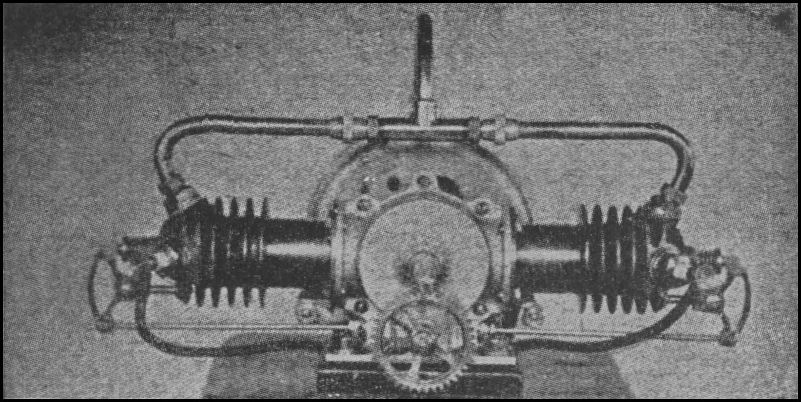
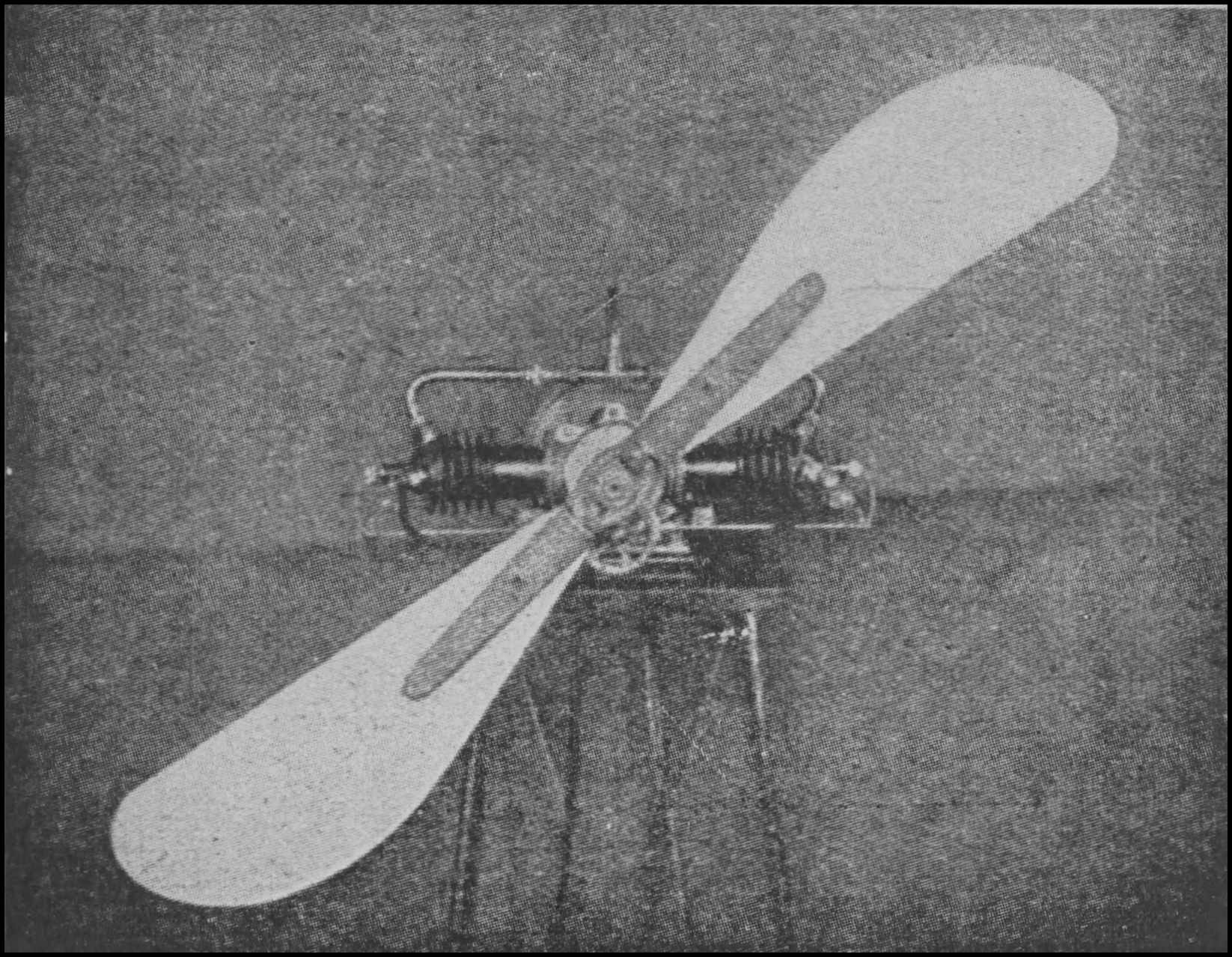
The interesting horizontal-opposed Jopson gasoline engine for model aëroplanes. The top photograph shows the half-speed shaft and the arrangement of the valve mechanism. This engine is air cooled, develops 1 h.p. at 1,500 r.p.m., and weighs 7¹⁄₂ lbs., including gasoline tank and propeller. The bottom view shows the engine with propeller in situ. Courtesy Flight.
As the accompanying diagrams 19 and 20 and photograph show, the engine is of the four-cycle, horizontal opposed type, having two cast-iron cylinders of 1¹⁄₄″ bore and 1³⁄₈″ stroke. Each cylinder is cast in one piece, and as the engine is air cooled, they are cast with radiating fins. One h.p. is developed at 1500 r.p.m. The total weight of the engine, gasoline tank and propeller is 7¹⁄₂ lbs. In preparing the design of this engine, the designs of similar full-sized aëro engines were followed as far as possible. The pistons are similar to those used on large aëro engines and are fitted with two rings; the crankshaft is turned out of two inch special bar steel, and is carried in two phosphor-bronze bearings. There is no special feature about the connecting rods, these being of the standard type, but very strong and light. To enable the two cylinders to be exactly opposite one another, the connecting-rods are offset in the pistons and are connected to the latter by gudgeonpins. The aluminum crank case is extremely simple, being cylindrical and vertically divided. The inlet valves are automatic, the exhaust valves being mechanically operated; the camshaft is driven from the main shaft by two-to-one gearing.
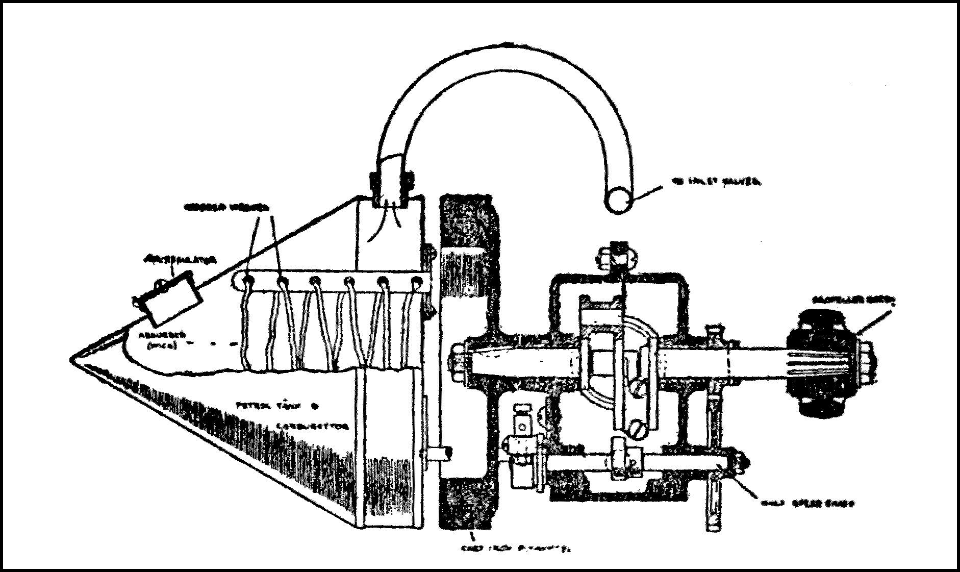
Diagram 19 Sectional elevation of the 1 h.p. Jopson gasoline engine for models. The disposition of the gasoline tank and wick carburettor is particularly noteworthy. It will be seen that metal journals are provided for the crankshaft, which is turned out of 2-inch bar steel. Courtesy Flight.
To assist the exhaust, and also the cooling, small holes are drilled round the cylinder in such a position that when the piston is at the inner end of its stroke, these holes are uncovered, thus permitting the hot exhaust to escape, and so relieve the amount passing through the exhaust valves. The commutator is also driven off the camshaft, as shown in the drawing. No distributor is fitted to the commutator, as small ones are somewhat troublesome and very light coils are obtainable at a reasonable price.
The gasoline tank is made of copper in streamline form, and is usually fitted to the back of the crankcase, thus reducing the head resistance, but if desired it can be fitted in any other position. The action of the carburetor can be easily seen from the drawings; it is of the surface type and much simpler, lighter and quite as efficient as the spray type. Specially light and simple spark plugs are used, that give very little trouble. The propeller used in connection with this engine is somewhat out of the ordinary, having been specially designed for this engine, and patented. The propeller is made entirely of aluminum and has a variable pitch, this being easily obtainable, as the blades are graduated so that any desired pitch, within certain limits, may be given at once. The results of a series of tests on a 30 inch propeller are shown on the accompanying chart, and from it the thrust as certain speeds with a certain pitch can be obtained. Taking the engine running at 1540 r.p.m. with a pitch of 15″, the thrust comes out at 9¹⁄₂ lbs., or more than the weight of the engine and accessories.
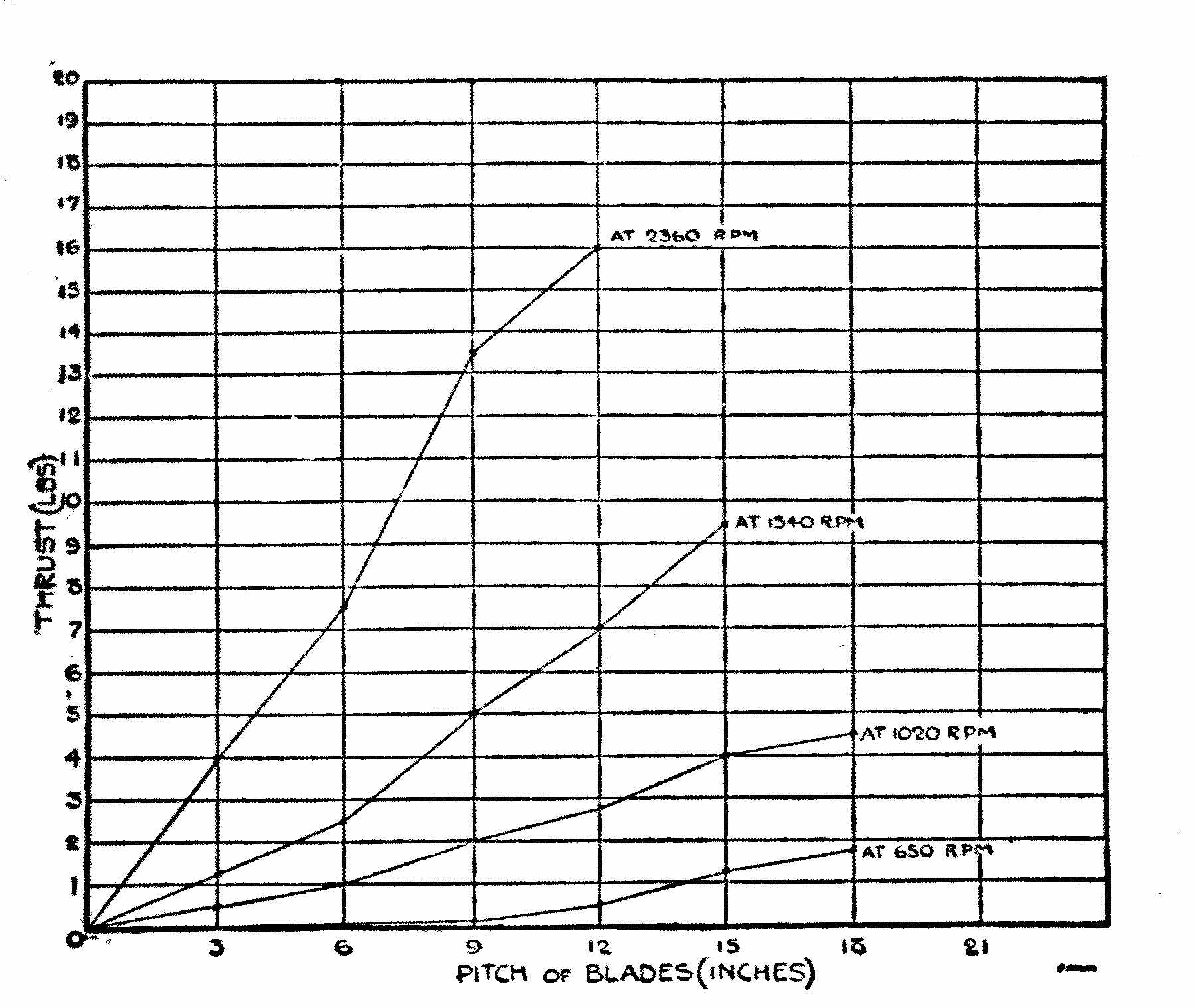
Diagram 20 Diagram of results obtained from tests of the 1 h.p. Jopson model gasoline engine, showing the thrust in pounds at varying speeds with propellers of different pitch. Courtesy Flight.
THE MIDGET AËRO GASOLINE ENGINE
Although numerous model constructors in America are experimenting with model gasoline engines, the Midget Gasoline Engine, the product of the Aëro Engine Company, Boston, Massachusetts, is perhaps the most satisfactory up to the present time. An engine of this type was used by Mr. P. C. McCutchen of Philadelphia, Pennsylvania, in his 8 foot Voisin Type Biplane Model, for which he claims a number of satisfactory flights.
The engine is made from the best iron, steel, aluminum and bronze and the complete weight including a special carburetor, spark plug and spark coil is 2¹⁄₂ lbs. From the top of the cylinder head to the bottom of the crank case the engine measures 7″. It is possible to obtain from this engine various speeds from 400 to 2700 r.p.m., at which speed it develops ¹⁄₂ h.p. The propeller used in connection with this engine measures 18″ in diameter and has a 13″ pitch.
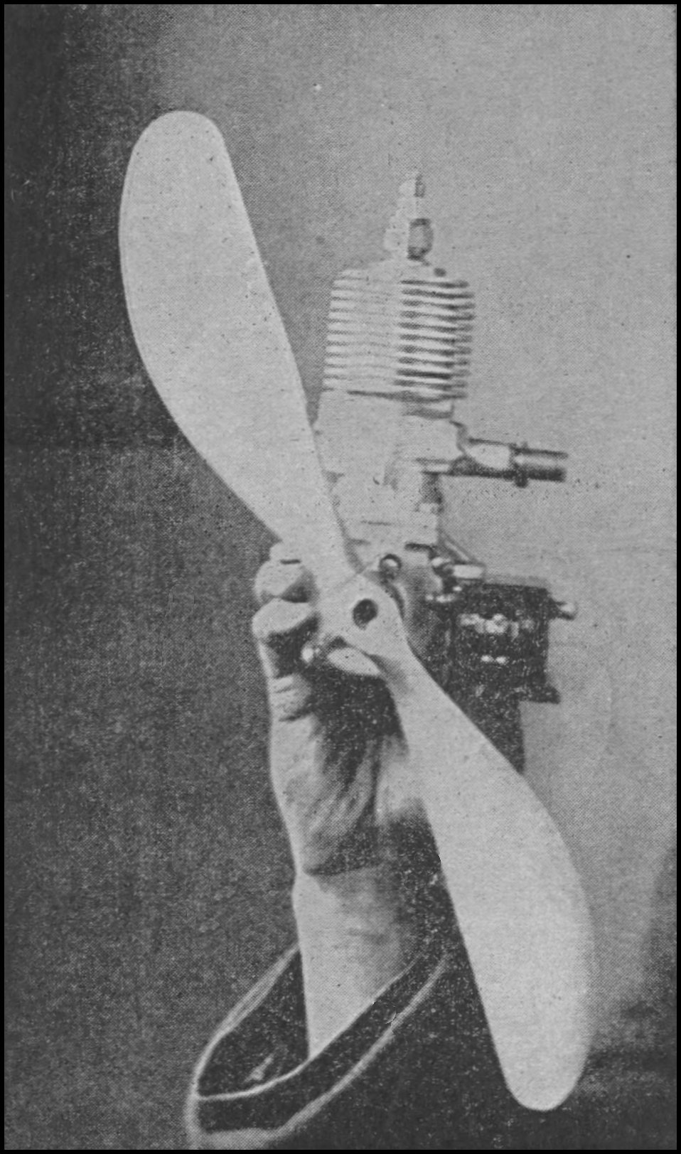
The Midget ¹⁄₂ H. P. gasoline engine
It might be of interest to know that one of the parties responsible for the development of this engine is Mr. H. W. Aitken, a former model maker and who is now connected with one of the largest aëro engine manufacturing companies in America.