CONSTRUCTION
Reading edition
PROPELLERS
Propellers may be cut from various kinds of wood, but the most suitable, from every standpoint, is white pine. The advantage of using this wood lies in the fact that the propellers may be cut more rapidly and when cut are lighter than those made from most other kinds of wood. When coated with the proper kind of varnish they are sufficiently strong for ordinary flying. Wood selected for propellers should be free from knots, holes and other imperfections and it is very desirable that it should be of perfectly straight grain.
A piece of such clear white pine 8″ long, 1″ wide and ³⁄₄″ thick should be selected and on one side marked Top. A tracing of the propeller similar in design to Figure 1, should be laid on this piece of wood and an imprint of the propeller design drawn on the Top side.
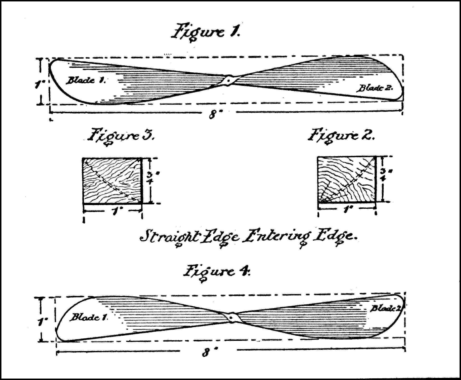
Diagram 1
To find the center of the block two lines should be drawn from the opposite corners, their point of meeting being approximately in the center—near enough for all practical purposes to insure greater accuracy. Similar lines should be drawn from the corners on the Bottom side of the block of wood. A hole ³⁄₃₂ of an inch in diameter should be bored through the center thus obtained, through which the propeller shaft will be inserted when the propeller is finished. The two sections of the propeller blades drawn in diagrammatical form on the Top of the block, should be marked respectively Blade 1 and Blade 2, as shown in diagram 1. The block is then ready for the commencement of the actual cutting. In cutting out the propeller, Blade 1 should be held in the left hand and the knife in the other, with the blade of the knife on the straight edge of Blade 1. The cutting should be carried out very carefully with attention constantly paid to Fig. 2, and should be stopped when the line shown in Fig. 2 has been reached. The semi-blade should then be sandpapered until a small curve is obtained by which the propeller will be enabled to grip the air.
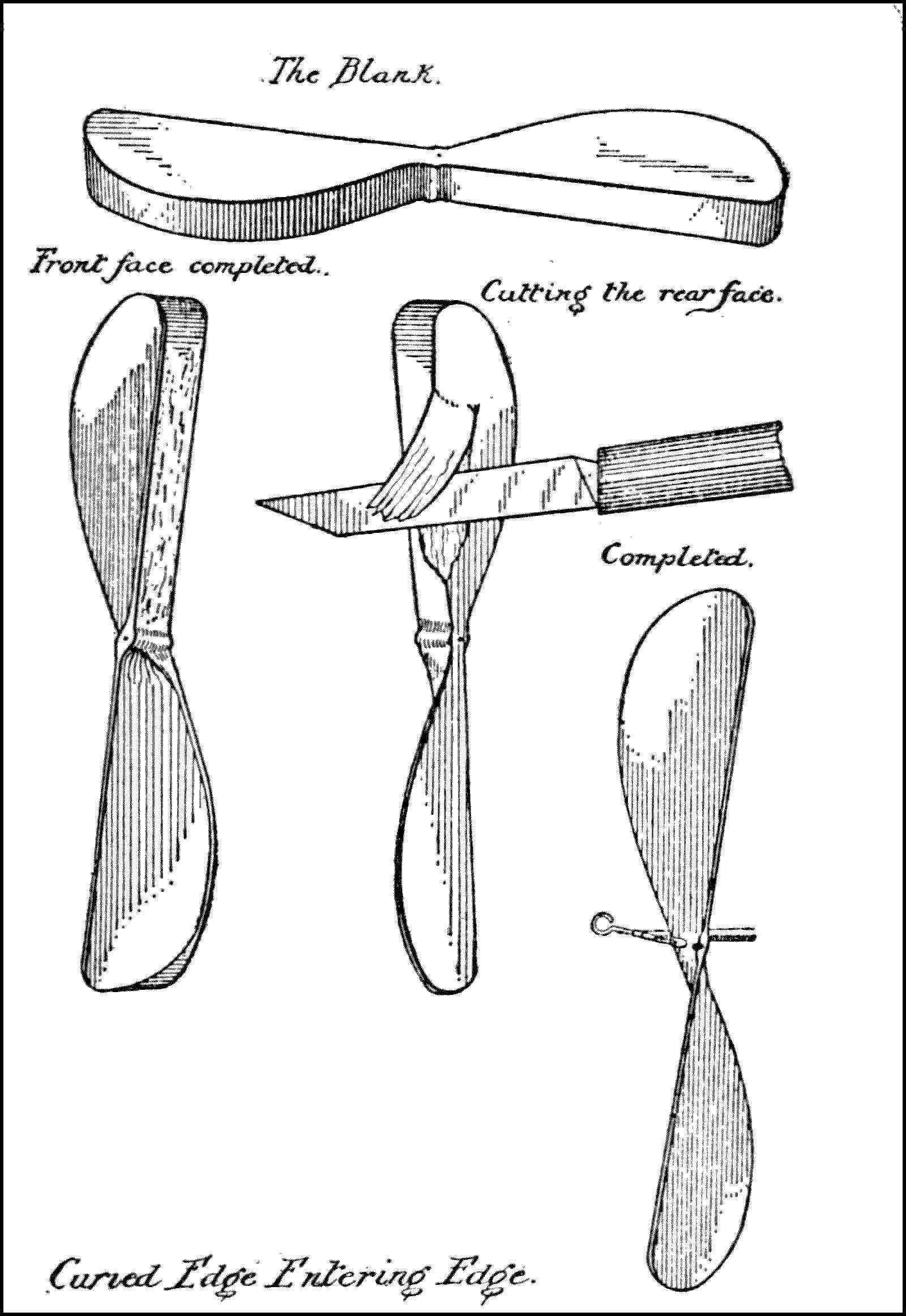
Diagram 2
To cut Blade 2, Blade 1 should be held in the left hand and Blade 2 cut until the line shown in Fig. 3 is reached, after which the sandpapering process is carried out in the same manner as in the case of Blade 1. During all of the foregoing operations it must be clearly borne in mind that the Top of the blank propeller must always face upward, and the cutting should always be done on the Straight lines. Should the straight edge be cut on one edge of the blank propeller and the curved edge on the other, it would result in the blades of the finished propeller having a tendency to push in opposite directions and in consequence no propulsion of the model would be possible.
Attention should next be turned to the back of the propeller blank on which the manner of cutting is exactly like that suggested for the top side, with the exception that instead of cutting along the Straight lines, the cutting is done along the Curved lines. In this part of the work great care is to be exercised for by the time the necessary cutting has been done on the back of the propeller the entire structure is very fragile and one excessive stroke of the knife may result in destroying the entire propeller blade. By constantly holding the wood to the light it is possible to determine with a reasonable degree of accuracy the evenness of thickness. To complete the Bottom side of the propeller the blade should be sandpapered as was the top.
The method of cutting the second propeller is exactly that used in cutting the first propeller, only that the diagram shown in Fig. 4 should be used. This will result in two propellers being made that will revolve in opposite directions in order to produce even and balanced propulsion. If both propellers revolved in the same direction the effect would be to overturn the model.
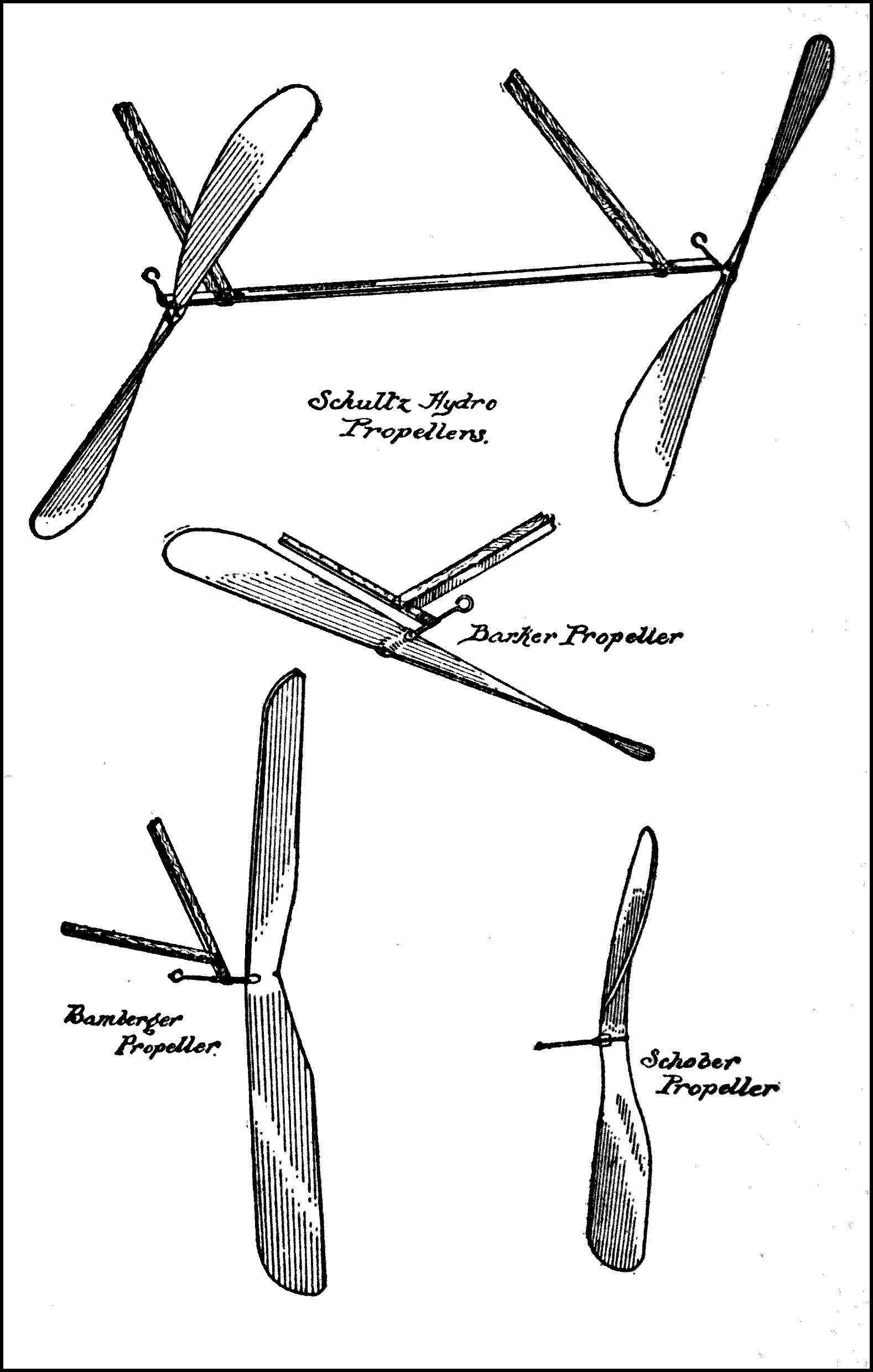
Diagram 3
In diagram 1 the propellers are shown with the straight edge as the entering or cutting edge of the blade. Some of the model builders prefer the curved edge as the cutting edge (diagram 2). It is significant that Mr. Frank Schober, a well known model constructor, tested both designs on his compressed air driven model, and while both propellers were the same in weight, diameter and pitch, the one having the straight edge as the cutting edge was found one-third more efficient.
When the propellers have been given a light coat of shellac they should be laid aside until the assembling of the complete model.
By following the foregoing instructions a simple and effective set of propellers will be produced. But in order to vary the experimental practice of the constructor various other diagrams, Nos. 3 and 4, illustrating suitable designs, are provided and can be made by applying the above general theory and using the diagrams herewith.
WINGS
One of the most important considerations in the construction of a model is the making of the wings. To obtain the greatest efficiency the wings must be carefully designed, with due attention to whether the model is being constructed for speed, duration or climbing ability. Attention should be given to streamline construction; that is, the parts of the wing should be so assembled that the completed wing would offer the least possible resistance to the air, if the best results are to be obtained.
For the main wing three strips of spruce, each 30″ in length, two of them being ³⁄₁₆″ × ¹⁄₄″ and the third ³⁄₁₆″ × ¹⁄₁₆″ are required. To make them thoroughly streamline all edges should be carefully rounded off and all surfaces should be smooth. A strip of bamboo at least 20″ long, ¹⁄₂″ wide, ¹⁄₈″ thick, should be cut into pieces, each piece to be 5 in. long. To secure the necessary curve, ¹⁄₂″ depth, the pieces of bamboo should be held in steam and slowly bent in a manner closely resembling the skids of an ordinary bobsled. When the curvature has been obtained, care should be exercised in cutting each piece into four longitudinal strips, from which twelve should be selected to be used as ribs, each to be ¹⁄₈″ wide. The bending of the bamboo preliminary to making the ribs is done in order to secure uniformity of curvature.
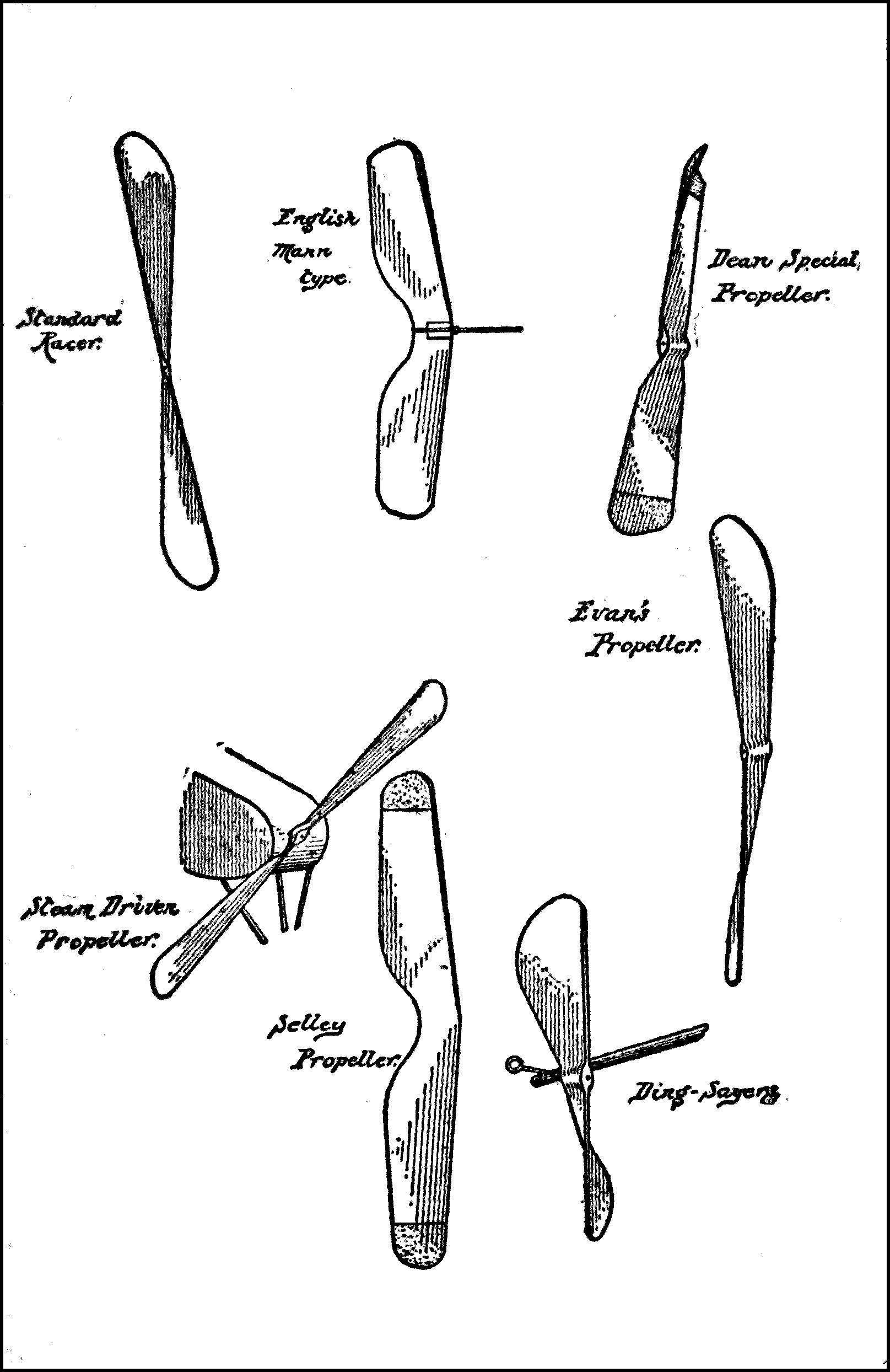
Diagram 4
When this has been done the ribs are ready for fastening to the sticks—entering and trailing edges—and each must be attached an equal distance apart. In order that the ribs may be evenly spaced it is necessary to put a mark every 3″ on the larger stick or entering edge of the wing, and also on the flat stick or trailing edge. The main beam which is of the same dimensions as the entering edge is afterwards fastened across the center of the wing, and does not necessarily need to be thus marked, as it is fastened to the ribs after the ribs have been attached to the entering and trailing edges of the wing frame. By holding the ribs one at a time so that the curved edge rests upon the entering edge where the mark indicates, as shown in diagram 5, they should be fastened thereon by means of thread and glue. The rear end of the rib must be fastened to the trailing edge where the mark indicates, also by thread and glue.
After all ribs have been thus securely fastened to both edges of the frame the third stick, or main beam, should be attached to the frame on the underside, the fastening being made at the highest point of the curve of each rib. This main beam prevents the wing covering from drawing in the end ribs and adds very materially to the strength of the entire wing structure. To cover the wings fiber paper may be used and is a suitable material, but the best results, from a standpoint of flying efficiency and long service, are obtained by the use of China silk.
The frame of the forward wing or elevator is made in the same manner as is the main wing, but it is only 12″ in span by 4″ in chord, and is constructed without the use of a main beam. This wing has only five ribs which are made in the same manner as those for the rear wing, and each is placed a distance of 3″ apart.
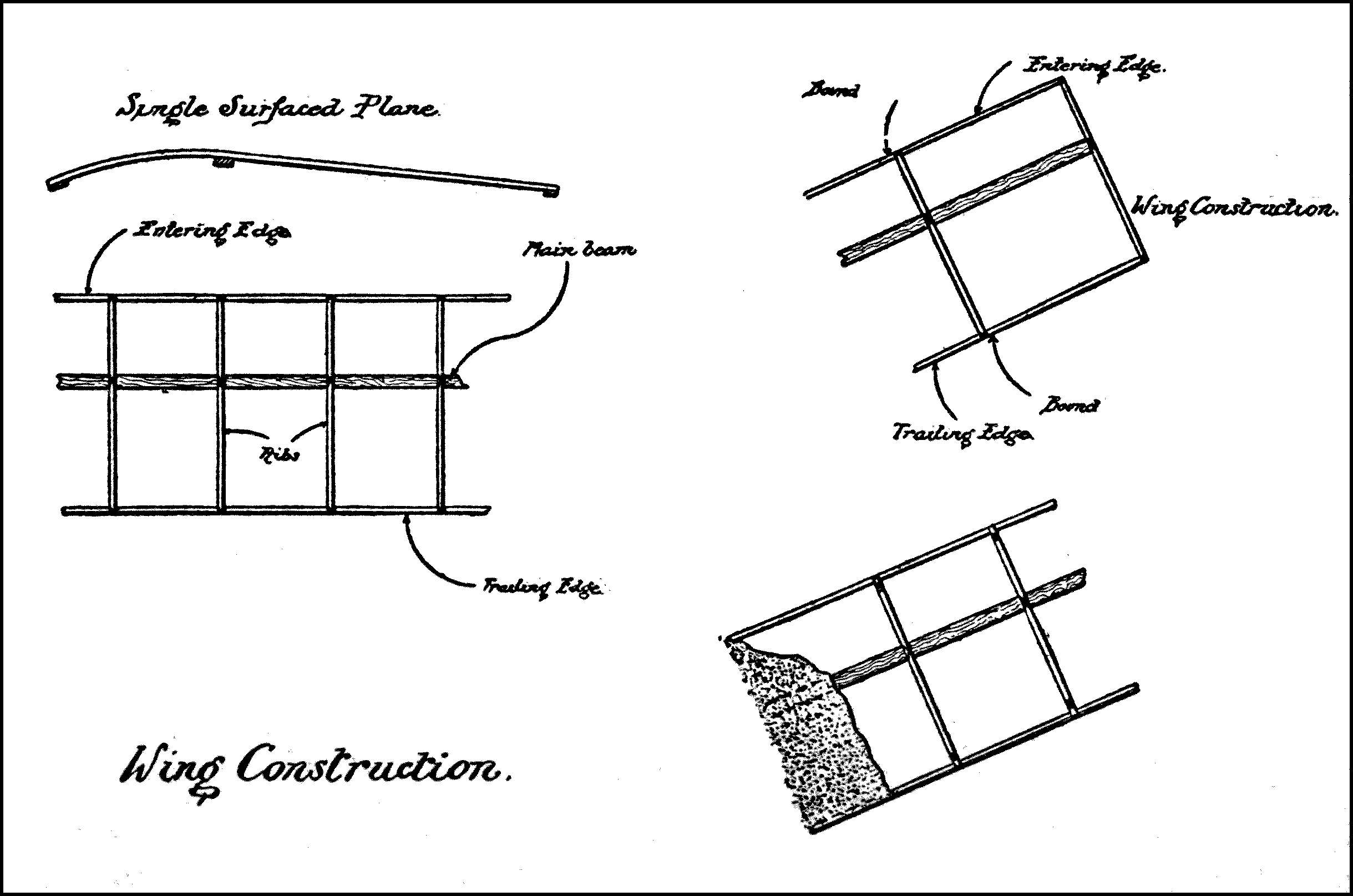
Diagram 5
A piece of silk measuring 2″ longer and 2″ wider than each of the wing frames should be used in covering the wings, and this can be held in position by the use of pins prior to the actual sewing. The extra inch of silk on all sides of the frame is placed around the under side of the frame—in order that it can be made thoroughly taut when the silk has been sewn close to the edges of the frame. After the silk has been sewn close to the edges the pins may be removed and the surplus silk that hangs from the under side of the frame may be cut off. To make this silk airproof it should be coated with a thin coat of shellac or varnish and the wings should be thoroughly dry before being used. This coating, in addition to airproofing, will assist in making the covering perfectly taut, and also in making the wing ready for service when the entire model is ready to be assembled.
FRAME
As all other parts of the model are attached to the frame in addition to its having to stand the strain of the tightly wound rubber strands which serve as the motive power for the model, it must be made strong. It is therefore necessary to exercise care and judgment in making certain that the different units that make up the frame are rightly proportioned and are of the proper material. Just as in the large sized aëroplanes there are many types of bodies, so there are many different types of frames in use in model construction, but the standard, and for all practical purposes the best frame, resembles the letter A in shape, hence the name A type. The lightness of the frame depends entirely on the materials used and the manner in which it is constructed.
Some model flyers use but a single stick for the frame, but generally the A type frame is preferred for the reason that it is more durable, the wings can be more securely attached to it, and that it is possible of developing very much better results.
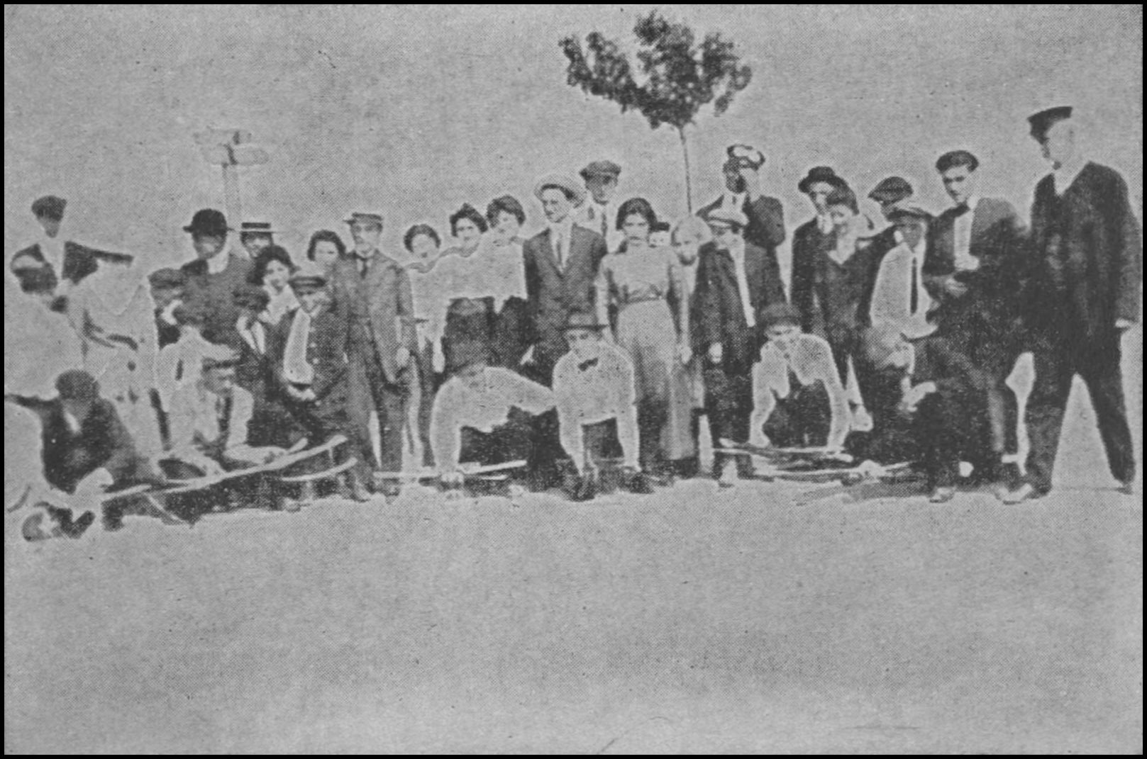
Members of the Aëro Science Club
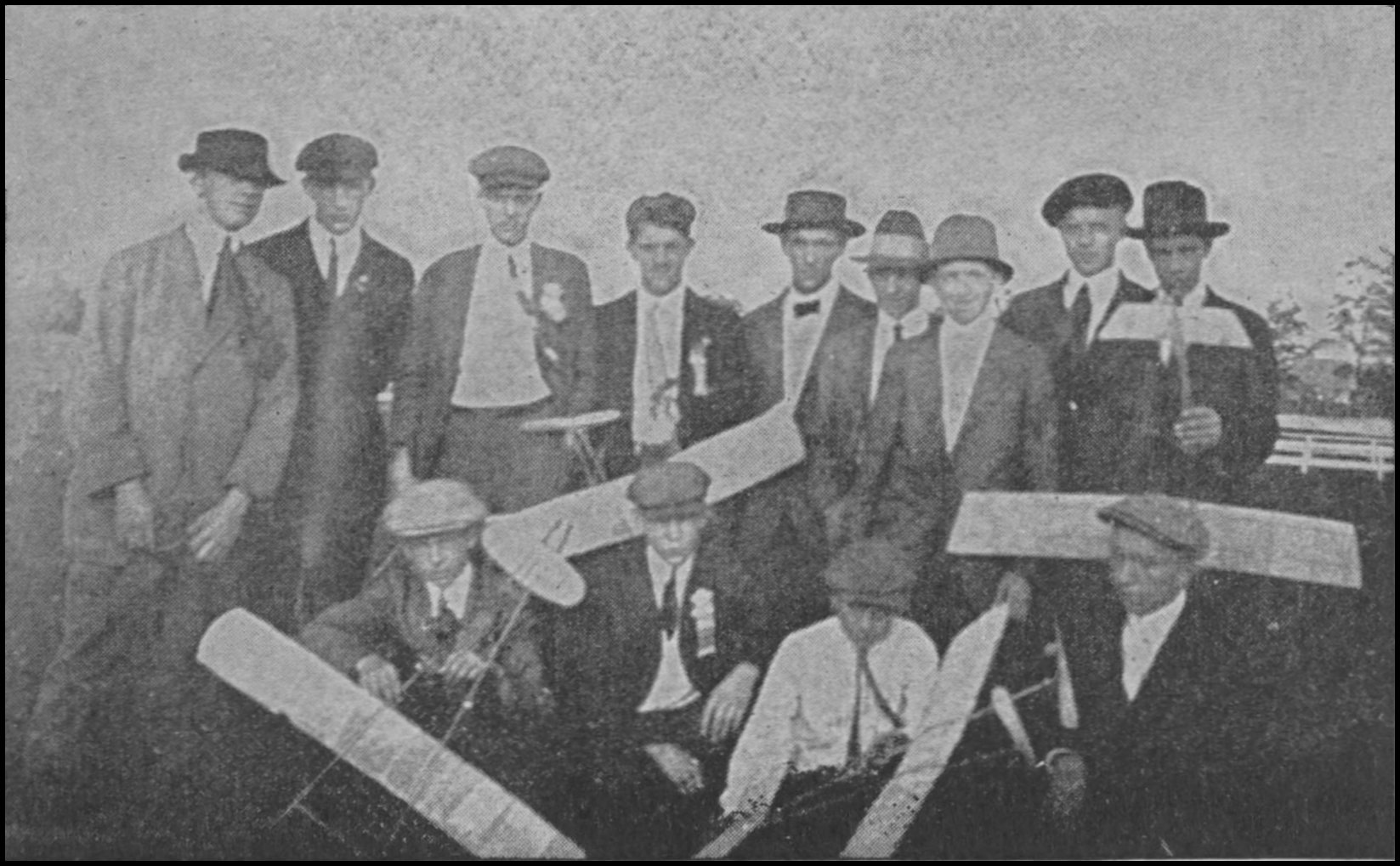
Members of the Milwaukee and Illinois Model Aëro Clubs
To construct such an A type frame 2 main sticks to serve as frame side members are necessary and are made from spruce. Each member should be 36″ in length, ³⁄₈″ in depth by ¹⁄₄″ in width. By rounding the edges and smoothing the various surfaces with sandpaper streamline effect will be secured and will add to the efficiency of the machine as well as to its appearance. When the side members are placed in A formation the extremity of the sticks at which they meet should be so tapered in the inner sides that when they meet and are permanently fastened the result will be a continuance of the general streamline effect. The permanent fastening of the frame side members at the point of the A may be accomplished by using either strong fish glue or better, a good waterproof glue and then have the jointure reinforced by securing a piece of ³⁄₃₂″ steel wire 3″ in length and placing the center of it at the point of the A, afterwards bending the wire along either outer edge of the frame side members, putting as much pressure on the wire as the strength of the structure will permit; after this the reinforced jointure should have thread wound around it to insure even greater strength. About ¹⁄₂″ of the wire on each side of the point should be left clear and afterwards turned into a loop as shown in diagram 6, for the purpose of attaching the hooks that hold the rubber strands. To hold the side members apart at the rear end and for a propeller brace, a piece of bamboo 10″ long, ¹⁄₈″ thick by ¹⁄₂″ in width is required and this should be fastened to the extreme rear ends of the frame side members, allowing the propeller brace to protrude on either side 1¹⁄₂″ as illustrated. To put the propeller brace in position a slot ¹⁄₂″ deep by ¹⁄₈″ wide should be cut into the rear ends of the frame side members for the reception of the propeller brace. After the brace has been placed in position the outer edge should come flush with the rear ends of the side members. To hold the brace in place thread and glue should be used in the same manner as described for the point of the frame side members. Between the point of the frame and the propeller brace two bamboo pieces, one 9″ long and another 2¹⁄₃″ long, should be used as braces for the general strengthening of the structure. The longest piece should be secured across the top of the frame about 9″ from the rear and the shorter piece about 9″ from the point.
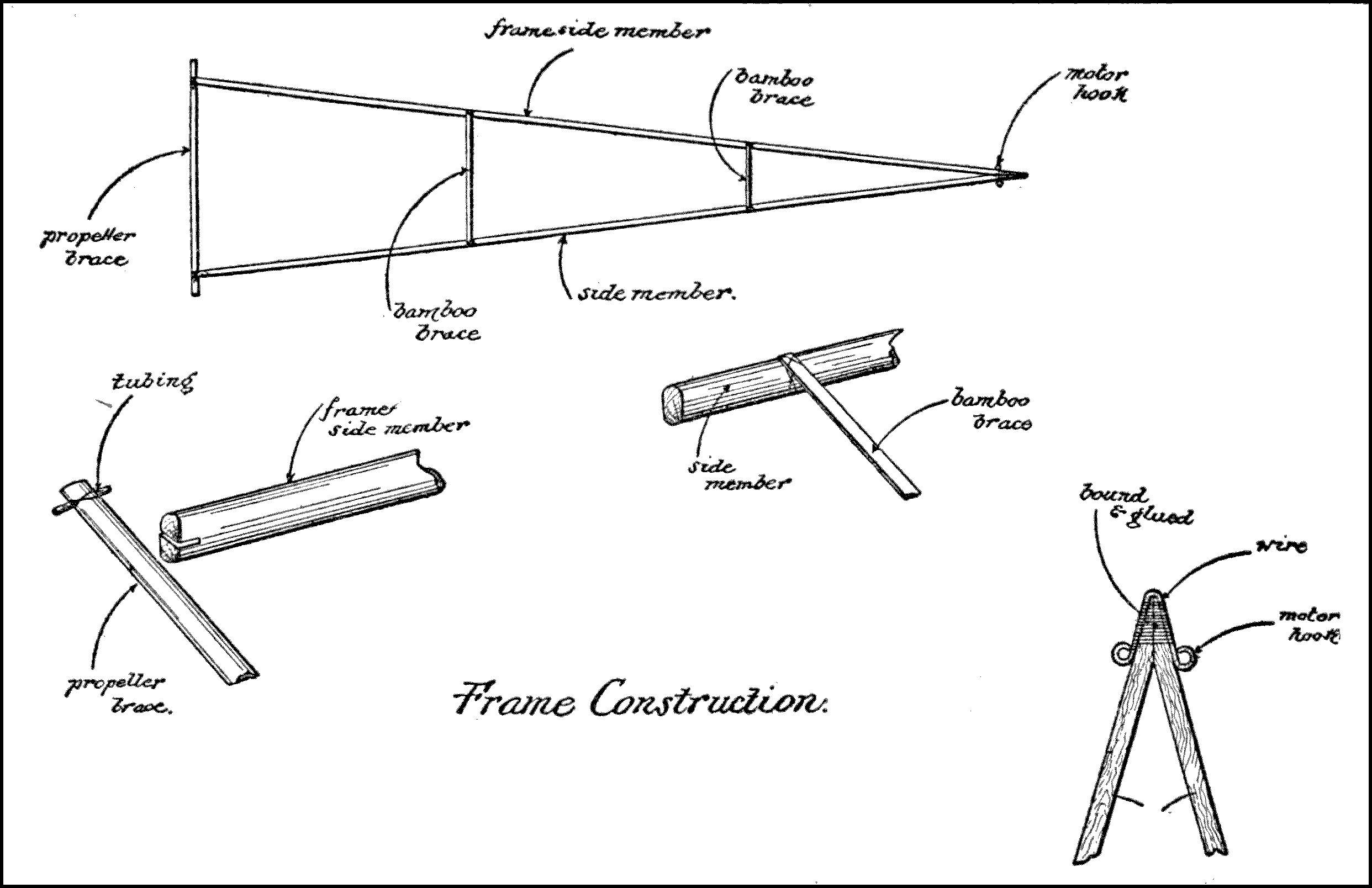
Diagram 6
When these two braces are in position the next matter that calls for the attention of the constructor is the matter of getting into position at the two outer extremities of the propeller brace bearings for the propellers. For this purpose two pieces of ³⁄₃₂nd inch brass tubing, each ³⁄₄th of an inch long, should be used, and should be fastened to the underside of the propeller brace, at each extremity of that brace, by the use of thread and glue. Sometimes greater efficiency is secured by putting these pieces of bronze tubing about ¹⁄₄″ from the end. Some model constructors make a very neat jointure here by soldering the piece of tubing to a strip of thin brass, which is bent over the end of the propeller brace and bound and glued thereon. In fastening the bronze tubing to the propeller brace it should be so adjusted that it will run parallel to the side members of the frame and will therefore offer the least possible resistance to the shaft of the propeller when the rubber strands have been attached.
When the frame has been completed a coat of shellac should be applied to the entire structure to render it damp-proof.
ASSEMBLING
The proper assembling of the parts of the model is as essential to good results as is the designing and making. Parts, although properly made, if improperly placed in relation to each other will very often lead to trouble. Therefore very great care must be exercised in the assembling process.
When all the parts have been prepared and are ready to be assembled the first thing that should be done is to mount the propellers in position. This must be done very carefully on account of the fact that the propeller shafts are easily bent and if bent the result is considerable trouble, for such a bend in the propeller shaft will cause the propeller to revolve irregularly with a consequent loss of thrust. Before inserting the propeller shafts in the tubing 4 washers each ¹⁄₄″ in diameter should be cut from hard metal, and a hole large enough for the propeller shaft to pass through should be bored in the center of each washer. The metal washers should be passed over the straight ends of the shafts which extend from the rear of the tubing, after they have been inserted in the tubing, and in this manner the cutting into the hubs of the propellers which would follow is avoided. The propellers are now to be mounted and this is accomplished by allowing the ends of the shafts, which extend out from the rear of the tubing, to pass through the hole in the hub of each propeller. In mounting the propellers it is absolutely necessary to have the straight edge of the propellers to face the point or front end of the model. The propeller shown in Fig. 4 of diagram 1, should be mounted on the left side of the frame to revolve to the left, while the propeller shown in Fig. 1 should be mounted on the right side of the frame to revolve to the right. When the propellers have thus been mounted the one-half inch of shafting which extends out from the hubs of the propellers should be bent over to grip the propeller hub and thereby prevent the shaft from slipping during the unwinding of the rubber strands. For the reception of the rubber strands to provide motive power a hook must be formed in each shaft and this can be done by holding securely that portion of the shaft which extends toward the point of the model, while the end is being formed into a hook as illustrated in diagram 7.
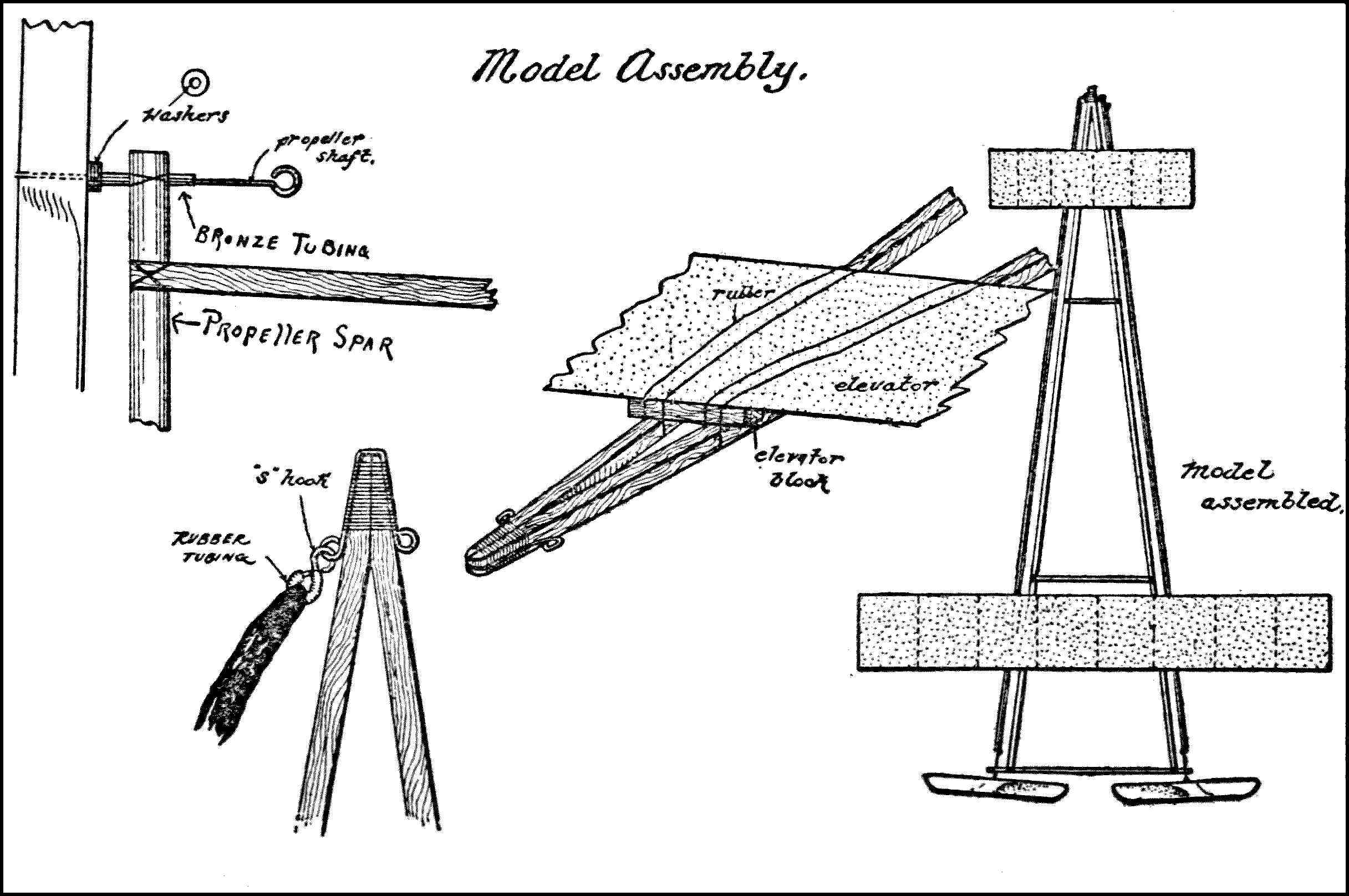
Diagram 7
Eighty-four feet of ¹⁄₈th″ flat rubber is necessary to propel the model. This should be strung on each side from the hooks (see diagram) at the front part of the model to the propeller shafts at the rear of the model. In this way 14 strands of rubber will be evenly strung on each side of the frame. To facilitate the winding of the rubbers two double hooks made of ³⁄₃₂″ steel wire to resemble the letter S, as shown in diagram 7, should be made. One end of this S hook should be caught on the frame hook, while the other end is attached to the strands of rubber, and to prevent the possible cutting of the strands a piece of rubber tubing is used to cover over all wire hooks that come in contact with the rubber strands providing propelling power.
The wings are mounted on the top side of the frame members by means of rubber bands and in placing them upon the frame it should be noted that the entering edge of each wing must face the point or front of the model. The wings must be so adjusted on the frame that they result in perfect side balance which means that there is an even amount of surface on either side of the model. To secure a longitudinal balance it will be found that the entering edge of the main wing should be placed approximately 8″ from the propeller brace or rear of the model, and the entering edge of the small wing or elevator approximately 6″ from the point. But it is only by test flying that a true balance of the entire model can be obtained. To give the necessary power of elevation (or lifting ability) to make the model rise, a small block of wood about 1″ long by ¹⁄₄″ square must be placed between the entering edge of the small wing and the frame of the model.
After the wings have been thus adjusted and a short test flight made to perfect the flying and elevating ability of the model, and this test flight has been satisfactory, the model is ready for launching under its full motive power.
LAUNCHING
In the preliminary trials of a model close attention must be paid to the few structural adjustments that will be found to be necessary and which if not properly and quickly remedied will result in the prevention of good flights or even in possible wrecking of the model. Careful designing and construction are necessary but it is equally as important that the model should be properly handled when it is complete and ready for flying.
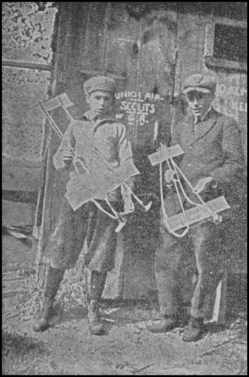
Charles W. Meyers and William Hodgins exhibiting models of early design.
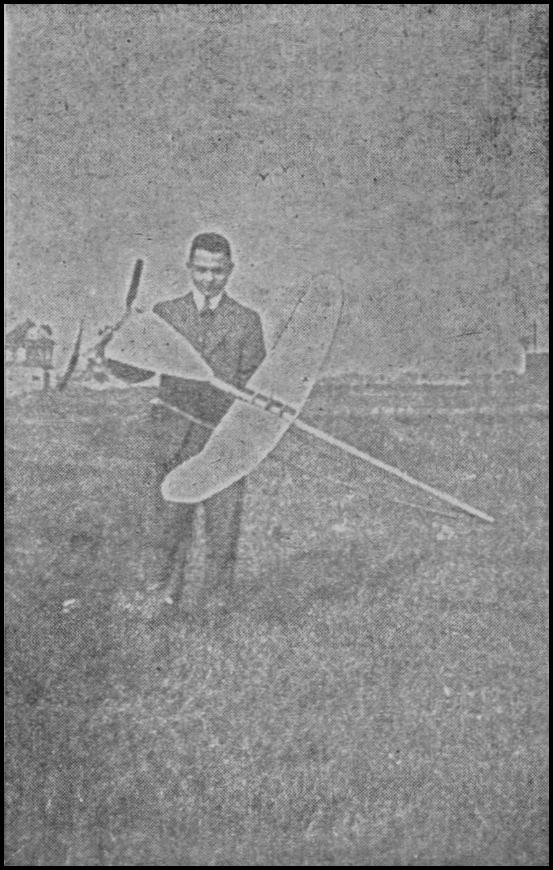
Henry Criscouli and his five foot model. This model may be disassembled and packed conveniently in small package.
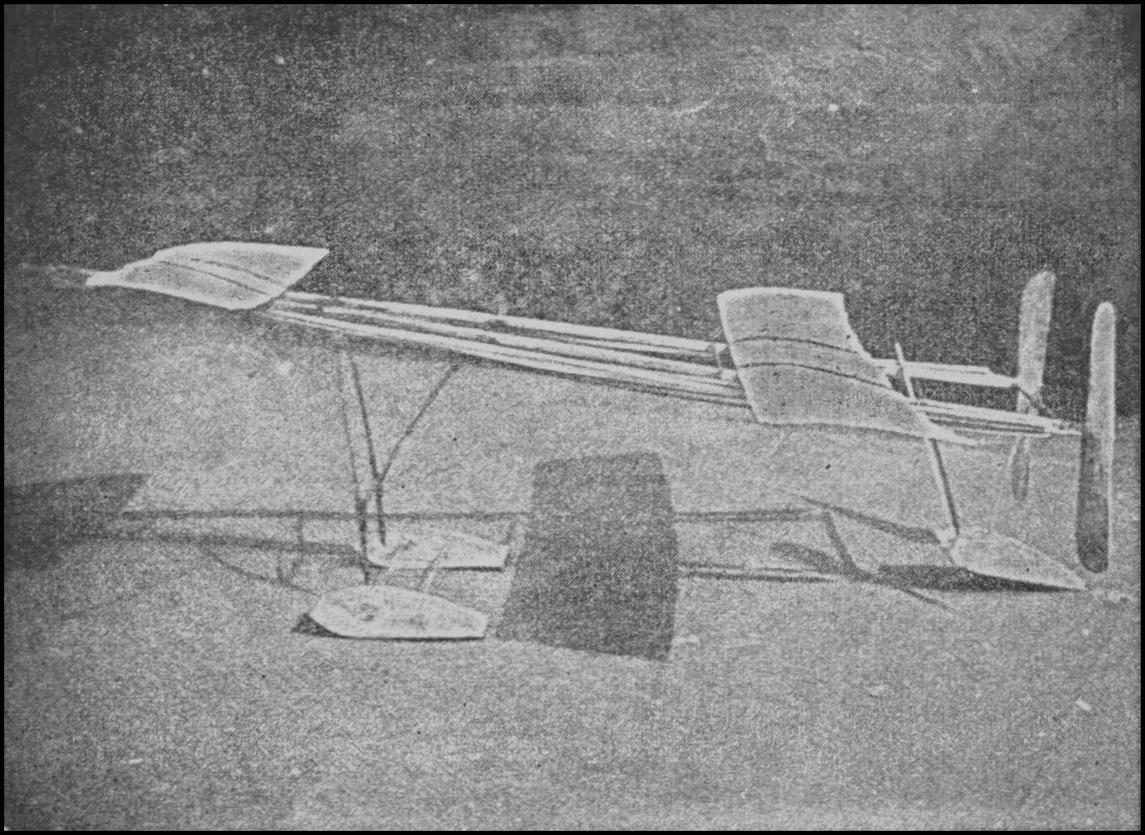
Harry G. Schultz hydroaëroplane.
The approximate idea of the balance of a model can be secured by launching it gently into the air. If the model dives down point first it indicates that the main wing should be moved a little toward the front. If it rises abruptly the main wing should be moved slightly toward the rear. In this way by moving the wing forward or rearward until the model glides away gracefully and lands flat upon the ground, proper adjustment of the balance can be effected. If when launching from the hand the model should curve to the left the main wing should be moved slightly to the left of the frame members. And if the curve is to the right the main wing should be moved in that direction. This process can be continued until the model flies in the course desired.
The winding of the rubber strands to get the necessary propelling power is an important detail. The model should be firmly held by some one at the rear with the thumb on either side member, pressing down on the jointure and with the four fingers of each hand gripping the under side of the frame members, and in this way holding the model steady and until the rubber strands have been sufficiently wound. With the hands in this position the propellers, of course, cannot and should not revolve. The hooks attached to the rubber strands at the point or front of the model should be detached from the side members and affixed to the hooks of the winder. A winder may be made from an ordinary egg beater as is shown in diagram 8. When the hooks attached to the rubber strands at the point of the model have been affixed to the winder the rubbers should be stretched four times their ordinary length (good rubber being capable of being stretched seven times its length) and the winding commenced, the person winding slowly moving in towards the model as the strands are wound. If the ratio of the winder is 5 to 1, that is if the rubber is twisted five times to every revolution of the main wheel of the winder, 100 turns of the winder will be sufficient for the first trial. This propelling power can be increased as the trials proceed. When the winding has been accomplished the rubber hooks should be detached from the winder hooks and attached to the hooks at the front of the side members as shown in the diagram.
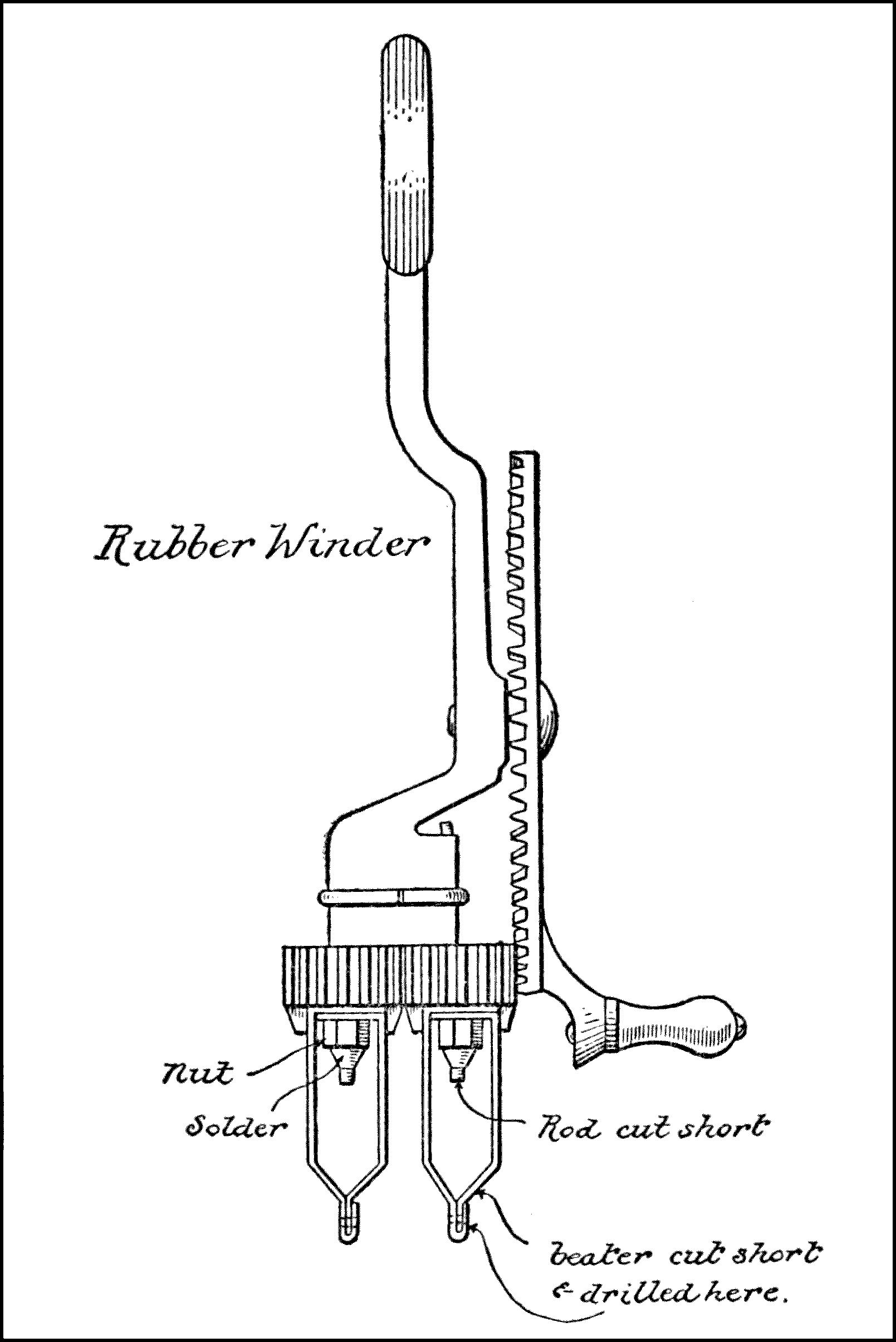
Diagram 8
In preparation for launching, the model should be held above the head, one hand holding it at the center of the frame, the other in the center of the propeller brace in such a way as to prevent the propellers from revolving. When the model is cast into the air if it is properly adjusted it will fly straight ahead.
A precaution which is sometimes worthy of attention before the launching of the model under its full power is to test out the propellers to find out whether or not they are properly mounted and whether they revolve evenly and easily. To do this the rubber strands may be given a few turns, enough to revolve the propellers for a brief period, while the machine is held stationary. If the shafts have been properly inserted in the hubs of the propellers and have not been bent during the winding of the rubbers, the propellers will revolve evenly and readily. If the propellers revolve unsteadily it indicates that there is a bend in the propeller shafts or the propellers have not been properly balanced. If the trouble is a bend in the shaft, it must be removed before the model is launched on actual flight. If the propeller does not revolve freely the application of some lubrication (such as vaseline) to the shaft will eliminate this trouble. With these adjustments made satisfactorily, the model can be launched with the anticipation of good flying.
CHASSIS
The preceding instructions and discussions have dealt with different parts of a simple model to be used as a hand-launched type of model. The experience which will come as the result of flying this type of model for a period will undoubtedly tend toward a desire on the part of the constructor to make his model more nearly represent a large sized aëroplane and will make him want to have his model rise from the ground under its own power. Such a model is known as an R. O. G. type, that is, rises off the ground.
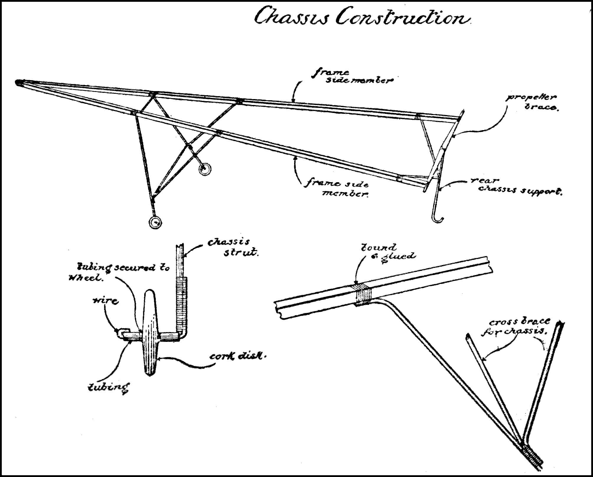
Diagram 9
To meet this desire all that it is necessary to do is to make a chassis, or carriage, which can be secured to the frame of the model, and with extra power added, will result in a practical R. O. G. model. In constructing such a chassis or carriage it is necessary to bear in mind that it must be made sufficiently strong to withstand the shock and stress which it will be called upon to stand when the model descends to the ground.
For the main struts of the chassis two pieces of bamboo each 9″ in length are needed and these should be bent over 1″ on one end as shown in the diagram, that they may be fastened to the under side of the frame members, one on either side, at a point on that member 12″ from the front. Two similar pieces of bamboo, each piece about 7″ in length, are required to act as braces between the frame members and the main chassis struts. Each end of each of the braces should be bent over in the same direction and in the same manner as that described for the main strut so that the fastening to the main frame member and the main chassis strut may be accomplished. Steam may be used in bending the ends of the pieces of bamboo. To make the landing chassis sufficiently stable to withstand landing shocks a piece of bamboo 9″ should be fastened from either side of the main chassis struts at the point where the chassis brace on either side meets with main strut. The ends of this cross brace should be bent in similar fashion to the other braces to enable its being fastened easily and securely.
Two small wheels constitute the running gear for the front part of the chassis, for which two pieces of ¹⁄₁₆″ steel wire each 2¹⁄₄″ long are required. These small wires are fastened to the bottom ends of the main struts, and to accomplish this the wire should be bent in the center at right angles; one leg of the angle is attached to the bottom end of the main strut as shown in the diagram. Disks for wheels may be cut from a bottle cork which should be ³⁄₄″ in diameter by approximately ¹⁄₄″ in thickness. The edges should be rounded off to prevent chipping. Before mounting the wheels on the axles which have been provided by the wires attached to the bottom of the main struts, a piece of bronze tubing ³⁄₃₂″ inside diameter and ³⁄₁₆″ long should be inserted in the center of each disk. To secure the least possible resistance on the revolutions of the wheels, there should be placed on the wire axles pieces of bronze tubing similar in diameter and ¹⁄₈″ in length on either side of the wheel (see illustration). When the wheel is thus placed in position with the pieces of bronze tubing on either side about ¹⁄₄″ of the axle wire will extend from the outward end of the outside piece of tubing. This should be bent over the tubing to prevent its falling off and at the same time hold the wheel securely in position.
For the rear skid a piece of bamboo 6″ long is used, one end of which is curved as in a hockey stick so that it will glide smoothly over the ground. The other end of the rear skid should be bent over about ¹⁄₂″ so that it can be securely fastened to the propeller braces, as illustrated in the diagram. Two 7″ pieces of bamboo are required to act as braces for the rear skid. Both ends of each brace strut are bent over ¹⁄₂″ in the same direction, one end of each strut is securely fastened to a side member 3″ from the rear and the other end of each strut is fastened to the rear skid, at their point of meeting as shown in diagram 9, the method of attaching being the same as in the case of the forward portion of the chassis. All joining should be accomplished by first gluing the braces and then binding with thread. When completed, the rear skid should glide along the ground in bobsled fashion, thus preventing the propellers from hitting the ground.
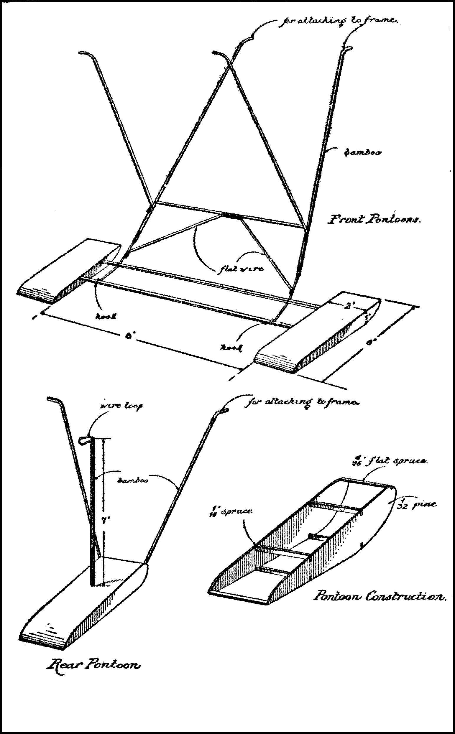
Diagram 10
In making such a chassis or carriage the endeavor should be made to use, as near as possible, the same weight of material on either side of the model so as little interference as possible will be made with the general balance of the model in flight.
PONTOONS
Having satisfactorily developed the hand launched model and the model rising off the ground under its own propulsion the constructor will next turn his mind to the question of having his model rise under its own power from the surface of the water in the fashion of passenger-carrying hydros and flying boats. This will be accomplished by the use of pontoons attached to a specially designed chassis.
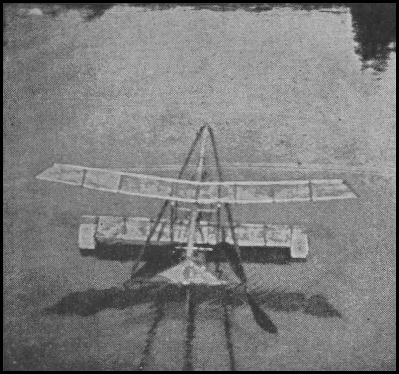
C. V. Obst World record flying boat
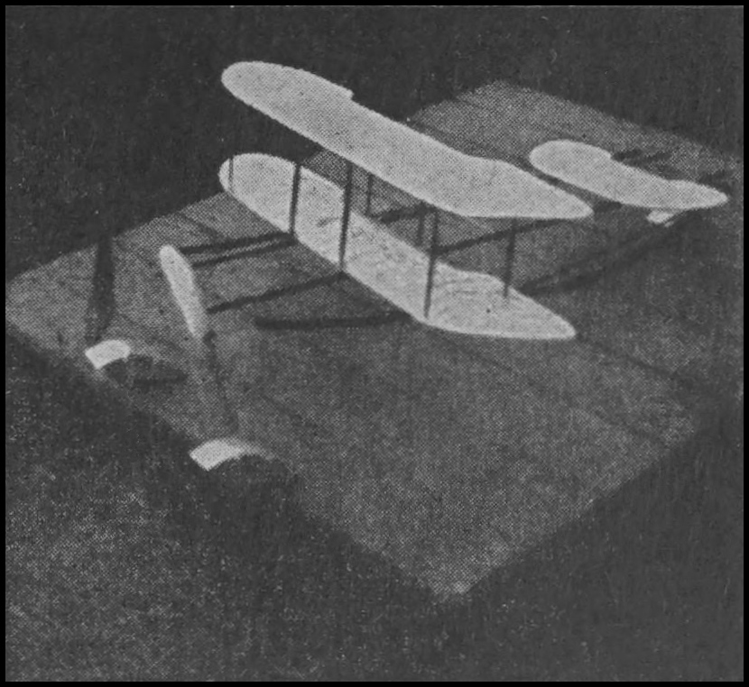
Twin tractor Hydroaëroplane designed and constructed by George F. McLaughlin
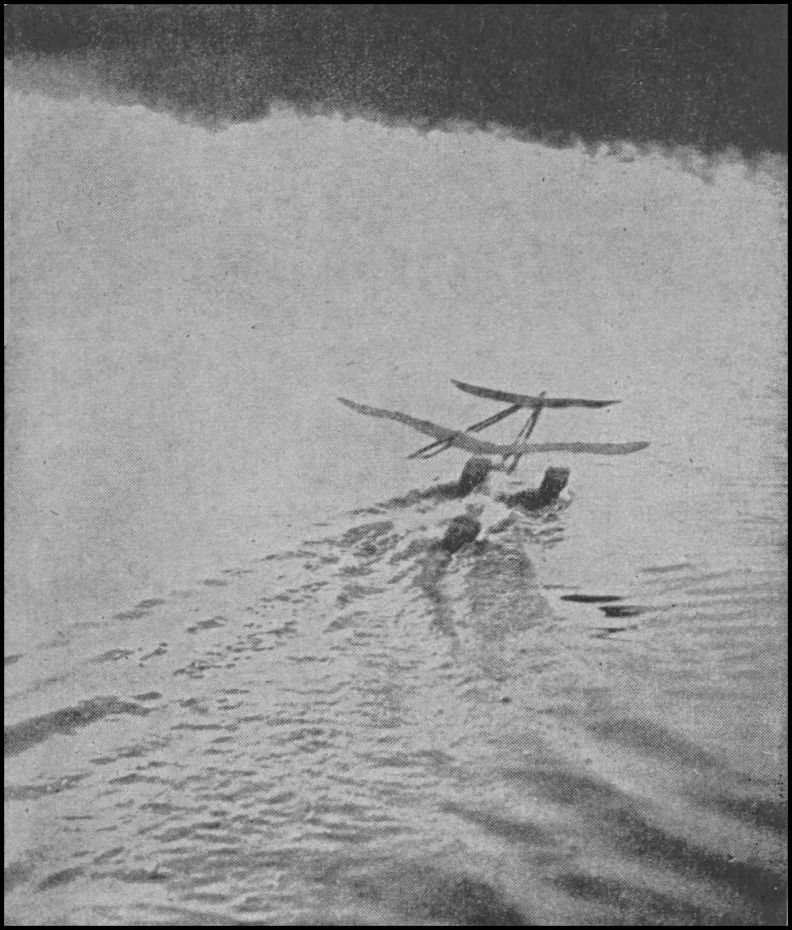
Louis Bamberger’s hydro about to leave surface of water
Three pontoons are necessary and these should be made as light as possible. Each pontoon should be made 6″ long, 1″ deep toward the forward part, by ³⁄₄″ at the rear and 2″ wide. The side members of each pontoon are made from pieces of thin white pine wood ¹⁄₃₂nd of an inch thick, slightly curved up at the front and sloped down toward the rear. Small niches should be made on the top and bottom sides of the pontoons into which the cross braces are inserted and glued. Further reference to diagram 10 will show that at the extreme forward end of the sides a cut is made large enough to receive a flat piece of spruce ¹⁄₁₆″ wide. Another cut of the same dimensions is made at the extreme rear end. Still further cuts are made on the top and bottom sides of the pontoons, the forward cuts measuring 1¹⁄₂″ from the front and the rear cuts 1¹⁄₂″ from the rear, to join the sides of the pontoons as illustrated in diagram 10. Six pieces of ¹⁄₁₆″ flat spruce are required for the rear pontoon, the ends of which are held in position by glue. For the forward pontoon only 4 braces are required in so far as the ends of the two main brace spars of the forward part of chassis are inserted in the cuts on the top sides of the pontoon. These brace spars measure 10 inches in length and are made from bamboo ¹⁄₈th inch in diameter, which necessitates enlargement of the cuts on the top sides of the forward pontoons so that the extreme ends of the spars can be inserted in the cuts in the place of the braces. To complete the rear pontoon and prepare it for covering, three strips of ¹⁄₈″ bamboo are required for struts. Two of these strips should measure 9″ in length and should be attached to the front of the pontoon on the inner side as shown in diagram 10. Thread and glue should be used in attaching the ends of the strips to the pontoon. To enable fastening to the frame the upper ends of the bamboo strips should be bent over about ¹⁄₂″. The third strip should measure 8″ in length and is attached to the upper and lower braces toward the front of the pontoon as shown in the diagram. It is necessary that this strip be secured in the approximate center of the pontoon to insure a good balance. For the purpose of securing the upper end of the third strut to the center of the propeller brace a piece of wire 1¹⁄₂″ long should be secured to the upper end of the strut and looped as shown in diagram 10. The three pontoons should now be covered with fiber paper and it is necessary to exercise care to avoid punctures. For the purpose of coating the fiber paper to render it waterproof, a satisfactory solution can be made by mixing banana oil with celluloid until it has attained the desired thickness, after which it should be applied to the covering of the pontoons with a soft brush.
For the main strut of the forward portion of the chassis two pieces of ¹⁄₈″ bamboo, each 11″ in length, are required and these should be bent over 1″ on one end as shown in the diagram, that they may be fastened to the under side of the frame members, one on either side at a point on that member 11″ from the front. Two similar pieces of bamboo, each piece 8″ in length, are required to act as braces between the frame members and the main chassis struts. Each end of the braces should be bent over in the same direction and in the same manner as that described for the main struts so that the fastening to the main frame member and the main chassis struts may be accomplished. Steam or an alcohol lamp may be used in bending the ends of the pieces of bamboo. To make the chassis sufficiently stable a piece of bamboo 7¹⁄₂″ should be fastened from either side of the main chassis struts at the point where the chassis brace on either side meets with the main strut. The ends of this cross brace should be bent in similar fashion to the other braces to enable its being fastened easily and permanently.
For the accommodation of the pontoons two strips of flat steel wire, each 4″ in length, should be attached to the ends of the main struts, about one inch from the bottom, the farthest ends should be bent to grip the second spar which joins the pontoons. Note diagram 10.
To further strengthen the chassis a strip of flat steel wire sufficiently long enough should be bent so that ¹⁄₂″ of the central portion can be securely fastened to the center of the cross brace as shown in diagram 10. The two outer ends should be bent down and are fastened to the wires which are attached to the bottom ends of the struts. This method of attaching the forward pontoons enables the constructor to adjust them to any desired angle and also detach them when not in use.
A model hydroaëroplane is one of the most interesting types of models and if properly taken care of will afford the constructor many pleasant moments.
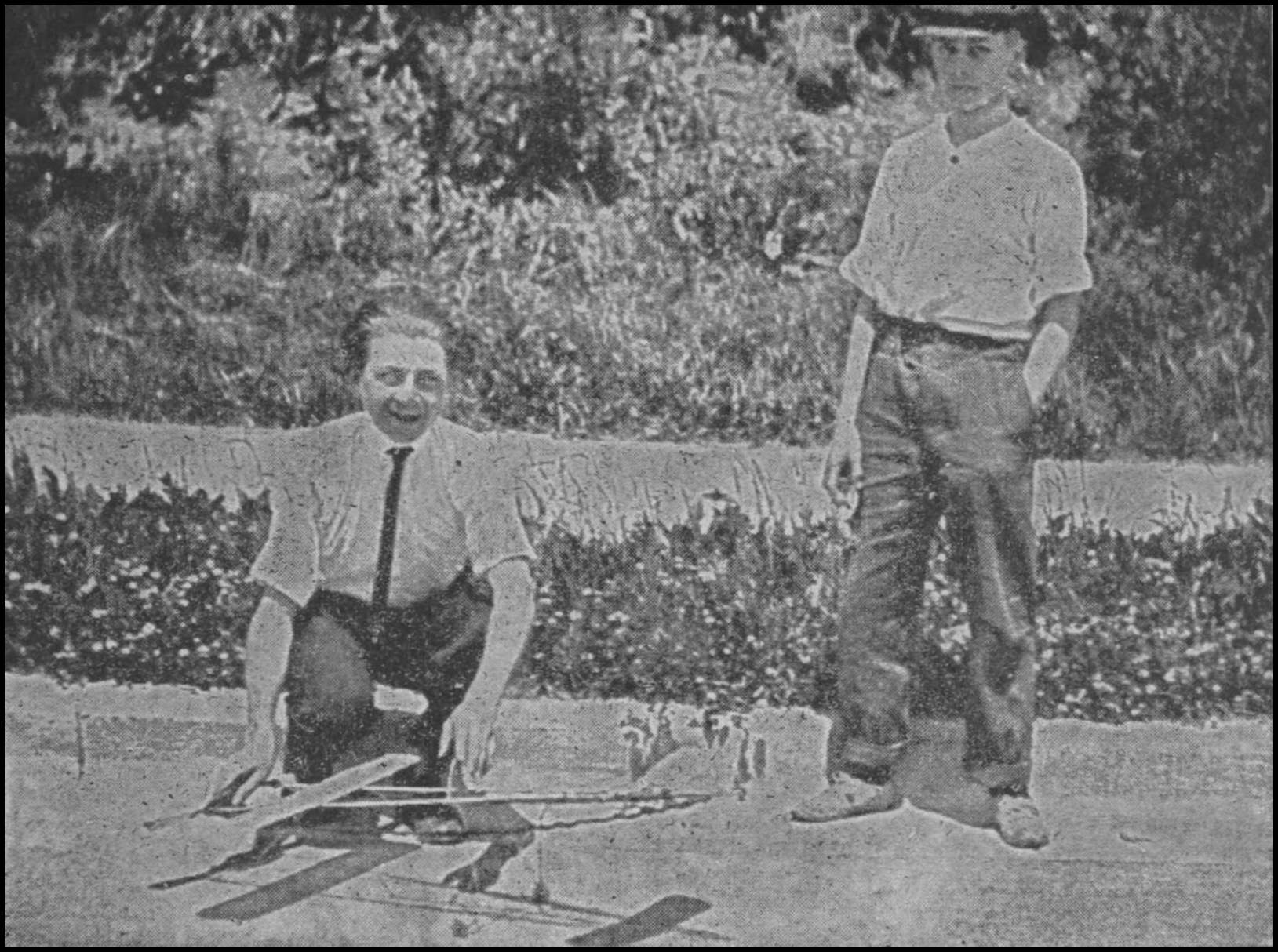
Erwin B. Eiring about to release R. O. G. Model. (Note manner of holding propellers.) Kennith Sedgwick, tractor record holder Milwaukee Model Club. Courtesy Gilbert Counsell.
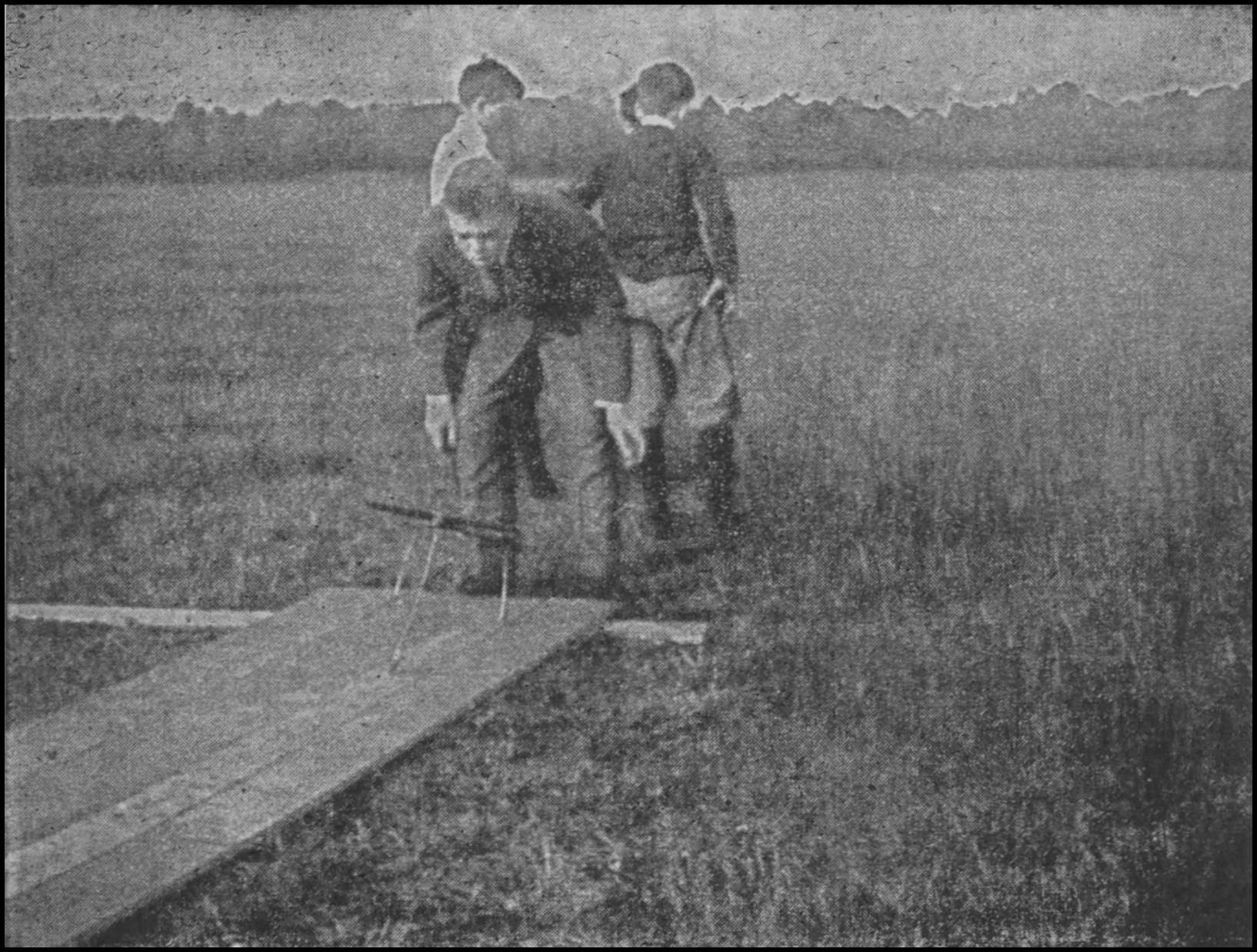
Waid Carl releasing R. O. G. Model. Courtesy Edward P. Warner.
LAUNCHING AN R. O. G. OR MODEL HYDROAËROPLANE
Although the method of determining the balance of an R. O. G. or a model hydroaëroplane is exactly the same as that of a hand launched model, the manner of launching is somewhat different. Instead of holding the model one hand in the center of the frame and the other at the rear as in the case of the hand launched model, in launching an R. O. G. or hydro, the model should be rested upon the ground or water, as the case may be, with both hands holding tightly to the propellers. Then when about to let the model go release both propellers instantly. If the model has sufficient power and it has been properly adjusted it will glide over the surface of the ground or water for a short distance, then rise into the air. Should the model fail to rise into the air additional strands of rubber should be added, after which it should be rewound and a second attempt made.
Should the model fail to respond after the addition of extra rubber, the indications are that something requires further adjustment. Perhaps the pontoons need further elevation if the model is a hydro, or if it be an R. O. G. model the forward wing may require an increase of elevation. In any event the model should be carefully examined and adjustments made where necessary, after which the model should be tested for balance and elevation. If satisfied with the behavior of the model after test flights have been made, another attempt should be made to launch the model from the ground or water.
On no account try to fly the model in the house, or see, supposing the model is of the R. O. G. type, if it will rise from the dining room floor. This advice may seem unnecessary, but it is not so, for there has been quite a number of instances in which the above has been done, nearly always with disastrous results, not always to the model, more often to something of much greater value. The smashing of windows has often resulted from such attempts, but generally speaking pictures are the worst sufferers. It is equally unwise to attempt to fly the model in a garden in which there are numerous obstructions, such as trees and so forth. A wrecked model is very often the result of such experimenting. The safest way to determine the flying ability of any model is to take it out in an open field where its flight is less apt to be interrupted.