COMPRESSED AIR DRIVEN MODELS
Reading edition
The development of the compressed air engine has given an added impetus to model making, necessitating more scientific experimenting and developing the art of model flying along lines of greater value to those who may eventually take up the work of building our future air fleets.
THE DART COMPRESSED AIR DRIVEN MODEL
In the accompanying illustration is shown a model aëroplane of monoplane type driven by a three-cylinder rotary engine which was constructed by Edward Willard Dart of South Norwalk, Connecticut.
The engine was constructed after several months of patient labor. Careful judgment was exercised in the drafting of the plane and likewise in the assembling of the engine for it is absolutely essential that all parts be properly fitted as to enable the engine to run smoothly. In designing the wings every detail was taken into consideration to insure good flying.
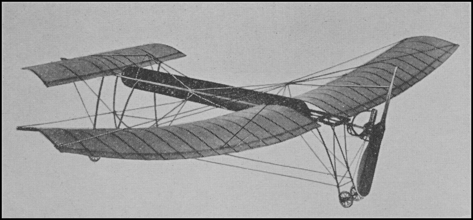
Model by Edward Willard Dart
The main wing has a spread of 58″ and 7″ in chord. The elevator measures 23″ in spread and 6″ in chord. In the construction of both wings bamboo ribs are used, the frames being covered over with China silk and coated with celluloid solution. The main wing is made in two sections to facilitate quick adjustment to the fuselage.
THE MCMAHON COMPRESSED AIR DRIVEN MONOPLANE
One of the latest developments in the field of model flying is the McMahon compressed air driven monoplane. This model was built to be used as either a tractor or pusher, but in view of its ability to balance more easily as a pusher most of the experiments have been carried out on this machine as a pusher. The machine in itself is simple and inexpensive to construct, the chief portion of the expense being involved in the making of the engine. By using the machine as a pusher a great deal of protection is afforded both the propeller and engine, and this protection helps to avoid damaging the propeller or engine, which would mean an additional expenditure for repairs, thus minimizing the cost of flying the model.
The frame has been made to accommodate both the tank and engine, and this is done by using two 30″ strips of spruce, each ¹⁄₄″ wide by ³⁄₈″ deep, laid side by side, a distance of three inches apart, up to within 10″ of the front, as shown in the accompanying photograph. No braces are used on the frame, as the tank, when securely fastened between the frame, acts in that capacity.
The wings are made in two sections, each section measuring 24″ in span by 8″ in chord, consisting of two main spars, ³⁄₁₆″ in diameter, one for the entering edge and one for the trailing edge. To these edges, at a distance of three inches apart, are attached bamboo ribs, 18 in all, each measuring 8″ in length by ¹⁄₈″ in width by ¹⁄₁₆″ thick. The wings are round at the tips, and have a camber of approximately one-half inch, but they are not set at an angle of incidence. Light China silk is used for covering and after being glued over the top of the wing frame is given two coats of dope to shrink and fill the pores of the fabric. A good “dope” for the purpose can be made from celluloid dissolved in banana oil. The wing sections are attached to the frame and braced by light wire. The forward wing or “elevator” is made in the same manner as the main wing, but should measure only 18″ × 3″. Instead of being made in two sections as the main wing, the forward wing is made in one piece.
The chassis is made by forming two V struts from strong steel wire sufficiently large enough so that when they are attached to the frame of the model the forward part will be 9″ above the ground. One V strut is securely fastened to either side of the frame, at a distance of 8″ from the front. A 7″ axle is fastened to the ends of these struts. On the axle are mounted two light wheels, each about 2″ in diameter. The chassis is braced by light piano wire.
The rear skid is made in the same manner as the forward skid, only that the ends of the struts are brought together and a wheel 1 inch in diameter is mounted at the bottom ends by means of a short axle. The struts are not more than 7¹⁄₂″ long, thus allowing a slight angle to the machine when it is resting upon the ground.
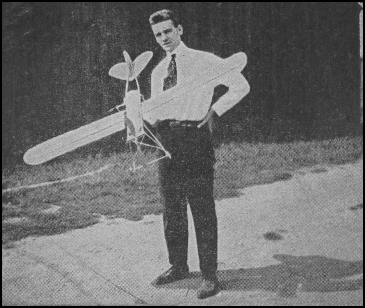
John McMahon and his compressed air driven monoplane
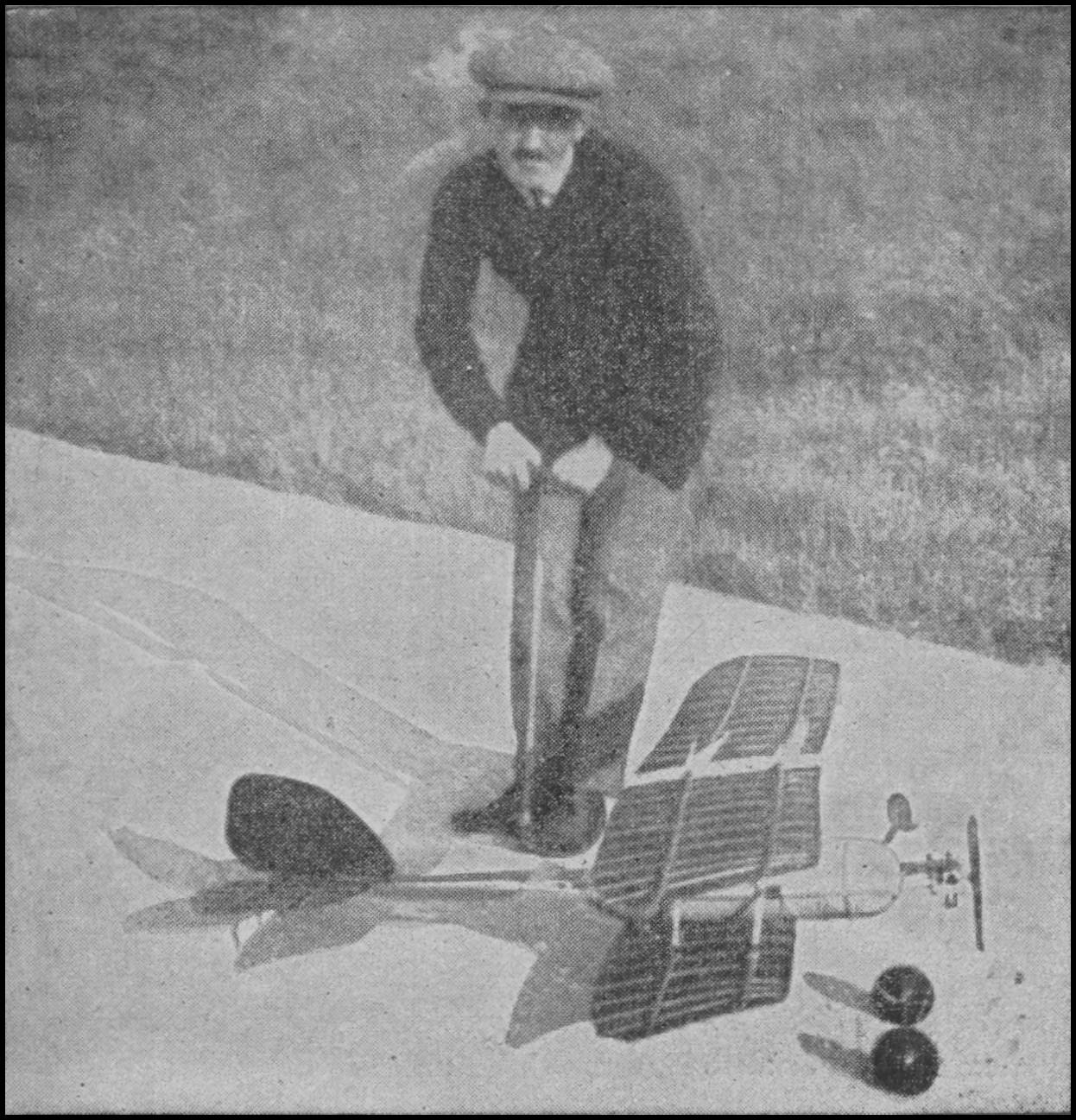
Frank Schober preparing his model for flight. Gauge to determine pressure of air may be seen in photograph
The machine complete does not weigh over 7 ounces. The power plant used in connection with this model is of the two cylinder opposed engine type, with tank such as has just been described in the foregoing chapter.
The tank is mounted in the frame by drilling a ¹⁄₁₆″ hole through either end of the tank, through which a drill rod of this diameter can be inserted. About ³⁄₄ths of the drill rod should extend out on each side of the tank, to permit the fastening of the tank to the frame side members. This method of mounting the tank serves two purposes to a satisfactory degree. First, it permits secure fastening; second, as the rods are passed through the side and cap of the tank they help materially in preventing the caps from being blown off in the event of excessive pressure.
THE MCMAHON COMPRESSED AIR DRIVEN BIPLANE
In the McMahon model we find a very satisfactory type of compressed air driven model. On several occasions this model has made flights of over 200 feet with a duration of between 10 and 15 seconds, and the indications are that by the use of a more powerful engine the model can be made to fly a greater distance, with a corresponding increase of duration. The engine used in connection with the model is of the two cylinder opposed type, such as described in the foregoing paragraphs. The tank, however, is somewhat different in design from that just described, it having been made of 28 gauge sheet bronze, riveted every one-half inch. The two long bolts that hold the steel caps on either end of the tank also serve as attachments for the spars that hold the tank to the engine bed, as shown in diagram 17. The tank has been satisfactorily charged to a pressure of 200 lbs. per square inch, but only a pressure of 150 lbs. is necessary to operate the engine. The tank measures 10″ in length by 3″ in diameter and weighs 7 ounces.
The wings of this machine are single surfaced and covered with fiber paper. The top wing measures 42″ in span by 6″ in chord. The lower wing is 24″ by 6″. The wings have a total surface of 396 square inches and are built up of two ³⁄₁₆″ dowel sticks, flattened to streamline shape. Only two sets of uprights separate the wings, thus adding to the streamline appearance of the machine.
Both tail and rudder are double surfaced and are built entirely of bamboo for lightness, the tail being made in the form of a half circle measuring 12″ by 8″. Steel wire is used on the construction of the landing chassis, the chassis being so designed as to render it capable of withstanding the most violent shock that it may possibly receive in landing. The propeller used in connection with the model is 14″ in diameter and has an approximate pitch of 18″.
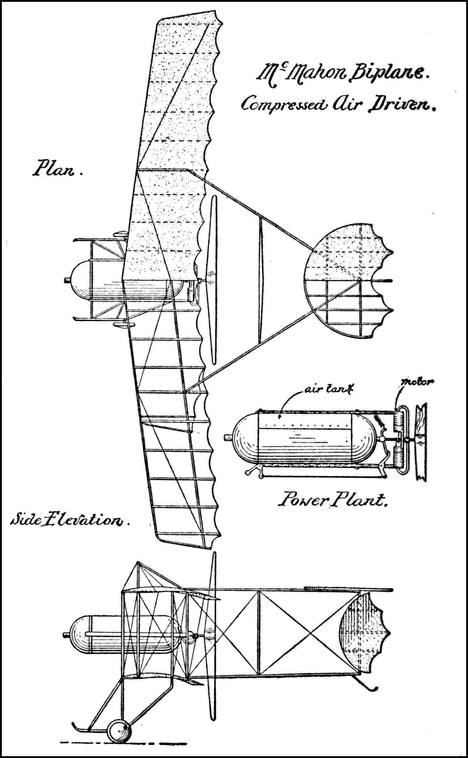
Diagram 17