COMPRESSED AIR ENGINES
Reading edition
THE WISE COMPRESSED AIR ENGINE
Although of peculiar construction, the Wise rotary compressed air engine offers a very interesting design from a viewpoint of ingenuity. This engine embodies a number of novel features not hitherto employed in the construction of compressed air engines, and in view of the fact that the majority of compressed air engines are made on the principle of the opposed type, this engine suggests many possibilities for the rotary type engine.
The engine consists of five cylinders and weighs four ounces, including the propeller and mounting frame. On a pressure of 15 lbs. the engine will revolve at a speed of 1000 r.p.m. The connecting rods are fastened to the crankshaft by means of segments and are held by two rings, making it possible to remove any one piston without disturbing the others. This is done by simply removing a nut and one ring. The crank case is made from seamless brass tubing, into which the cylinders are brazed. The valve cage and cylinder heads are also turned separately and brazed. One ring only is used in connection with the pistons. The cylinders have a bore of ¹¹⁄₃₂″, with a piston stroke of ⁷⁄₁₆″. In view of the fact that pull rods show a greater tendency to overcome centrifugal force, they are used instead of push rods to operate the valves. The crankshaft has but one post, which is uncovered in turn by each inlet pipe as the engine revolves. The “overhang” method is used to mount this engine to the model. With the exception of the valve springs, the entire engine, including the mounting frame and tank, is made of brass.
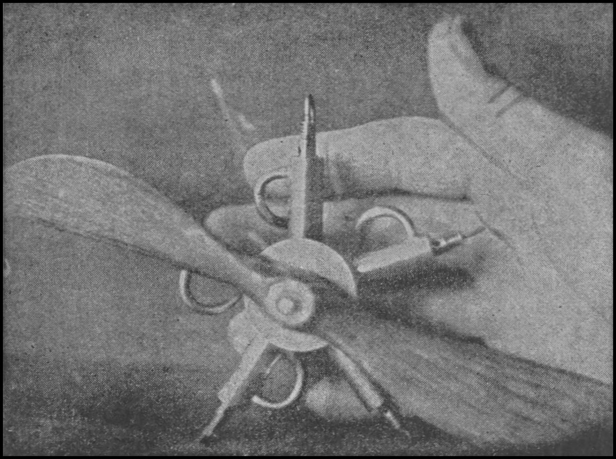
Wise five cylinder rotary compressed air engine
THE SCHOBER-FUNK COMPRESSED AIR ENGINE
Two of the most enthusiastic advocates of the compressed air engine for use in model aëroplanes are Messrs. Frank Schober and Rudolph Funk, both members of the Aëro Science Club. For a number of months both these gentlemen have experimented with compressed air engines of various designs, until they finally produced what is perhaps one of the most satisfactory rotary engines now in use, from a standpoint of simplicity and results.
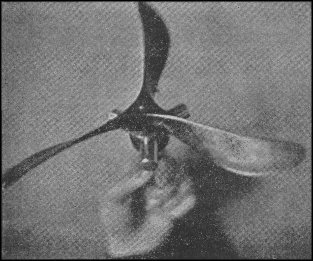
Schober-Funk three cylinder rotary engine
As can be seen from the accompanying illustration, this little engine is remarkably simple in appearance. The engine complete, with equipment, weighs at the most but 14 ounces. The cylinders, three in all, are stamped from brass shells for strength and lightness. The pistons are made from ebony fiber. The cylinders have a bore of ⁵⁄₈″, with a piston stroke of ¹⁄₂″. The crank case is built up from a small piece of brass tubing and is drilled out for lightness. The crankshaft is hollow, and is supported at the rear by a special bearing which acts as a rotary valve, admitting the intake through the crankshaft and permitting the exhaust to escape through a specially constructed bearing.
The tank is constructed of 30 gauge sheet bronze, wire wound, and fitted at the ends with spun brass caps. The actual weight of the engine alone is 2¹⁄₂ ounces, the tank and fittings weighing 11¹⁄₂ ounces, making the total weight of the complete power plant 14 ounces.
THE SCHOBER FOUR CYLINDER OPPOSED ENGINE
Another interesting type of compressed air engine that has been developed in America is the Schober four cylinder opposed engine. While this engine is different in appearance from most compressed air engines, it has been made to work satisfactorily and is consistent with the same high class construction that is displayed in most all of Mr. Schober’s engines. The accompanying diagram 18 illustrates the method of operation of the four cylinder engine.
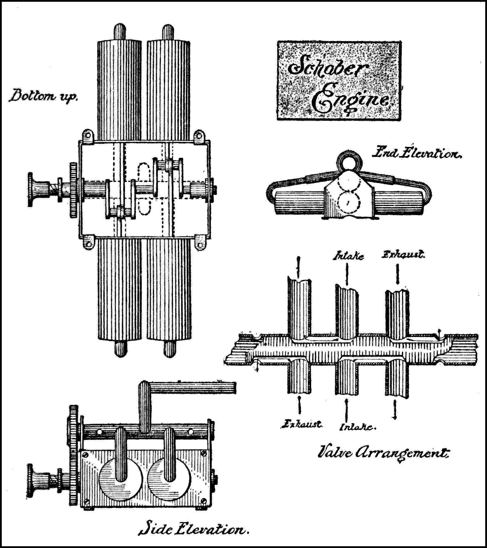
Diagram 18
The crank case is constructed from four pieces of 24 gauge spring brass, substantially connected in the form of a rectangle, the top and bottom being left open. The front and rear walls have flanges which engage the inside of the side walls and are secured thereto by four small screws on each side, thereby making it an easy matter to take the crank case apart.
The four cylinders are made from drawn brass shells and have a bore of ¹⁄₂″ and stroke of ¹⁄₂″. The pistons are made of solid red fiber. The two-throw crankshaft is built up of steel with brass webs. The bearings are of steel. The valves, being overhead, are driven by a gear mounted at the end of the crankshaft, the gear driving the valve shaft by means of a gear on that shaft, with which the crankshaft gear meshes. The valve arrangement, as shown in diagram 18, consists of four recesses cut into the valve shaft, two of which allow the air to pass from the inlet pipes, which lead into the valve chamber at the center of same, to two of the cylinders at once, while the other two recesses allow the exhaust to pass from openings in the sides of the valve chamber.
The cylinders are secured to the side plates of the crank case so that when those side plates are removed, the cylinders are removed with them. The pipes are detachable at their centers; small pipes running to the heads of the cylinders extending into the larger pipes which run to the valve chamber. This arrangement is shown in the end view of the engine. A 17″ propeller is used in connection with this engine.