MILL DESIGN
Reading edition
SITE AND ARRANGEMENT PRELIMINARY CONSIDERATIONS
INTRODUCTION
1. The requirements of the modern factory building are many, and demand the careful attention of the architect in their planning and construction. There are probably more rules and regulations imposed by the state and local governments and by the Insurance Underwriters, regulating the construction of this class of buildings, than for buildings of any other character.
The laws imposed by the governments under whose jurisdiction the building is to be erected, are framed manifestly for the protection of the health and safety of the occupants of the building, and so as not to jeopardize their lives in case of fire or panic, or the lives of those engaged in the attempt to save the structure and prevent damage to the adjoining property.
The Underwriters, or the Association of Insurance Companies, have compiled numerous rules and regulations of which the architect planning the building must take cognizance if he desires to secure a reasonable rate of insurance on the building and its contents for the owner. Not only do these rules and regulations deal with the structural design of the building, but they consider the apparatus for protection in case of fire, and such installations as the electric wiring. The architect must be familiar with all these requirements in order to intelligently and practically design industrial plants.
There are, also, many factors essential to the utilitarian and economic operation of the building entering into the design of the modern factory, to which the architect must devote careful study. Among the most important of these are the economic receiving, shipping, elevation, and transportation of merchandise; the proper and adequate lighting of the building; the location and planning of the power plant for the building, together with the engineering problems of construction, which include the design of the floor, columns, and walls for the loads to which they are subjected.
CLASSIFICATION OF FACTORY BUILDINGS
2. Classified according to their construction, factory buildings may be divided into three types, which, for convenience, may be designated as first-, second-, and third-class buildings. A similar division to this is also frequently made by the state or municipal laws for the regulation of the construction of factory buildings.
3. First-Class Buildings.—Buildings of the first class are those in which the walls, floors, columns, girders, beams, partitions, and roofs are of stone, brick, terra cotta, concrete, steel, iron, and such other fireproof materials as have been proven to be efficient. Buildings of this class may be considered as constituting an entirely fireproof building, which means that while the contents of the building may burn, the building itself will remain intact, unless subjected to the severe action of a prolonged conflagration.
4. Second-Class Buildings.—Buildings of the second class are considered to include what is known as slow-burning, or the typical factory-construction, type, in which all posts or girders must be of heavy and massive timber, and the floor construction at least 3 inches in thickness, and of solid planking. In buildings of the second class, while it is permissible to use combustible materials, they must be of such sizes and of such slow combustion that the security of the building will be insured for a reasonable time after the conflagration has commenced. It is usual, therefore, in this class of building, to limit the size of the wooden posts to not less than 8 inches square, though their strength may be greatly in excess of the load they are required to support, and girders and beams are used whose least dimension is 6 inches or more. In buildings of this character, it is frequently necessary to use steel beams and columns in order to obtain the strength for the great floor loads to which these members are liable to be subjected. When such steel or iron columns are used, however, they must be fireproofed, because even though made of incombustible material, they would not have the same endurance in a fire as have heavy wooden girders or posts, and their failure would precipitate the fall of the floor. Wooden girders and posts, even when charred part way through, have still sufficient strength for the support of the load for which they were designed.
5. Third-Class Buildings.—Buildings of the third class are not particularly recommended for the construction of factory buildings, for the floors of these may be of the ordinary joist and finished floor construction. Such buildings are readily ignitible and burn rapidly, not only because the timber work in them is light, but because of the numerous air spaces that exist between joists and in the furring of the walls. No building with air space surrounded by combustible materials can be considered as slow burning.
FACTORY PLANNING
6. Considerations in Planning.—The outline of the building is determined by the site, and owing to irregularities in the site generally purchased for manufactory purposes, it is frequently difficult to properly design buildings of this character. The factors that probably influence the design mostly, after the location of the column supports, and consequently the spacing of the windows has been determined upon, are the stairways and elevators.
In many cases, these are the only subdivisions of the main-floor plans, and in order to comply with the rules and regulations of the local or state governments, and of the Underwriters’ Association, they demand primary consideration. The stairways must as well be easy of access, while the elevators must be conveniently located for the delivery and receipt of goods from the first floor of the building.
Another factor that is likely to enter into consideration of the design is the toilet rooms, which must be placed against an outside wall, and convenient to any part of the floor.
ARRANGEMENT OF STAIR TOWERS
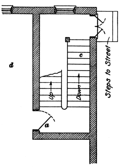
Fig. 1
7. The Enclosed Stairway.—The important consideration in the planning of factory stairways is to provide a quick, easy, and safe egress for the occupants in case of fire. While it is necessary to have good liberal stairways for communication between the floors, this is not such an important feature in factory design, from the fact that there is little travel of employes between the floors, in a modern factory, as each individual’s work is usually apportioned to him and confined to a particular location, and therefore does not require him to be on different floors during the day.
The common type of factory stairway is that designated in Fig. 1. This shows a brick-enclosed stairway with the doors entering it direct from the factory. Such a stairway enclosure as this should have tin-lined doors as at a, which fireproof the opening. Even then the security of a stairway of this character is not certain, from the fact that these doors may be left open, and are open to the stairway during the egress of the occupants. With a severe fire, therefore, on any floor, such a stairway is likely to be filled with smoke to suffocation, and liable to ignition from the door openings. It can therefore only be regarded as a makeshift for a fire-escape, or fire-tower. It is also well, in the design of such a stairway, to observe that the doors always open outwards, and not only this, but that they open with the tide of people coming down the stairs. For instance, in the figure the door a is opened correctly, but if the flights of steps marked down and up were transposed, then people coming down the flight c would press against the door at a and prevent the people in the room d from getting out to the stairs and hence to safety.
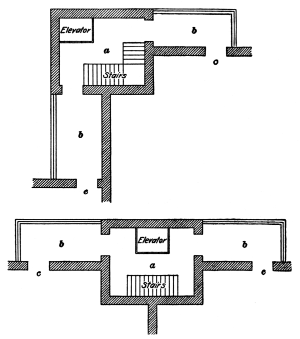
Fig. 2
8. Enclosed Fire-Escape, or Stair Towers.—Various designs for brick-enclosed stairways of factory buildings have been recommended at different times by the insurance companies. Two of these designs are designated in Fig. 2 and show the elevator included, as well as the stairway, in the tower.
A study of these plans will show that there is no direct communication from the building to the stair tower, and that the only way by which the stair tower may be entered is through an open balcony, which communicates with a door in the side walls of the building, at each floor. The brick-enclosed stair tower is shown in the figure at a, the open galleries at b, and the door of egress from the factory at c. By means of this arrangement, the occupants of each floor can, in case of fire, go through the door in the side wall, on to the open balcony, and into the fire-tower, thence down stairs or elevator to the ground floor and safety. Because of the openness of the balcony, which is surrounded with a strong rail, and partially covered by the gallery above, the fire could hardly be sufficiently great on any floor to make it untenantable, and no smoke or flames could communicate with the fire-tower.
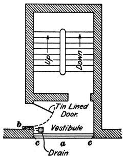
Fig. 3
9. Vestibule Fire-Tower Stairway.—While the arrangement just described is rational, the fire-tower is of such dimensions as would ordinarily preclude its use in the modern building where ground space is valuable and every inch of surface must be economized.
The best possible design, therefore, for a fire-tower is that indicated in Fig. 3. This construction is known as the vestibule fire-tower, and from the plan it is seen that this combines safety and utility in a small amount of space. The opening marked a in the plan is always open to the weather, and the floor of the vestibule is usually concreted and graded to a drain that connects with the rain conductor of the roof at b. By this arrangement, a well-protected line of travel is obtained between the stairway and the buildings on each floor, the occupants of the building being protected by the parapet wall and iron railing, as indicated at c c. To this vestibule from the factory a tin-lined, or fireproof, door must be provided, so that after the people have left one floor it can be cut off from the vestibule.
In the construction of all fire-towers, their walls must be carried by means of parapet walls at least 3 feet above the roof of the building, and the roof over them must be constructed of fireproof material.
When it is required, fireproof windows may be used in the walls of brick-enclosed fire-towers. These windows may be constructed of sheet metal and glazed with wire glass. If it is not possible to use such windows, a skylight may be built over the top of the tower, but this skylight must be constructed of sheet metal, or other non-combustible material, and glazed with wire glass.
10. Number of Fire-Towers.—The number of tower fire-escapes required for factory buildings of either the first, second, or third class, may be established according to the number of stories in height of the building, and the floor area, in square feet, for each floor; that is, for buildings of the first class, three or four stories in height, having one tower, the floor area of any floor may be as much as 20,000 square feet, while if the height of the building of the same construction is made twelve stories, the floor area should only be 6,500 square feet.
Where two tower fire-escapes are incorporated in the plan, a building three or four stories in height may contain as many as 25,000 square feet in the area of one floor, but if the building were increased to twelve stories, the floor area of each floor should not exceed 15,000 square feet.
In buildings of the second and third classes, a greater number of tower fire-escapes should be provided, and it is good practice to supply one tower fire-escape in a three-story building of these classes for a floor area not exceeding 10,000 square feet, or two tower fire-escapes should the floor area not exceed 15,000 square feet. In buildings of this construction, of from four to six stories in height, the floor area should not exceed, for one tower fire-escape, from 6,000 to 3,500 square feet of floor area in each floor, while with two tower fire-escapes the maximum floor area is from 12,000 to 8,000 square feet.
11. Location of the Fire-Tower.—Where two tower fire-escapes are used in a building, they must not be located near to each other, the purpose always being to provide a second egress in case of one being cut off by smoke or flame.
In small buildings of considerable height, it is sometimes difficult to so arrange the plan as to provide two stairways at extreme ends or corners of the building. In a case like this, it is frequently necessary to extend balconies along the side of the building, entering the fire-tower at some more distant point.
ELEVATOR SHAFTS
12. Location of Shaft.—In all factories of two or more stories, an elevator is a necessity for the economic transmission of goods from one floor to another. While in some instances the elevator is run through hatch openings in the floor, without being enclosed in brick walls, it is not good practice, for the openings through the floors make possible the rapid communication of flames and smoke in case of fire, even when provided with an automatic closing hatch. Elevators are therefore generally built in an elevator shaft, the walls of which are constructed of good hard brick and made from 12 inches to 18 inches in thickness.
13. Elevator Doors and Openings.—In building elevator shafts, it is necessary to provide door openings at each floor, the openings being protected with tin-lined fireproof doors. These doors may be either folding or sliding-doors, it usually being considered best to provide a sliding-door that will automatically close when a certain temperature has been reached in the building. It is not always possible, however, to provide sliding-doors, from the fact that where the elevator shaft projects out into the room and the door opening is wide, there is no wall space on which to fasten the track. Customarily, in each door opening, there is also provided a heavy stone or cast-iron sill. As in many states the law requires some automatic, or folding, lift gates for elevator openings, it is the practice to project this sill inside of the shaft at least 4 inches, in order to provide a bearing and protection for such gates.
14. Construction of Openings.—The openings in the brick walls of an elevator shaft are constructed ordinarily with rowlock brick arches, and from the fact that the openings are usually wide, and little jamb is left on each side of the opening, it is necessary to build 1-inch round iron rods in the arch above the opening, these tie-rods being furnished with washer plates at each end.
The jambs of all openings in the elevator shafts should be protected with cast-iron fenders made of about ½-inch metal, and so constructed as to return about 4 inches on each face. These jambs are provided with heavy wrought-iron anchors, which are built into the brickwork in the process of construction.
(a)
(b)
Fig. 4
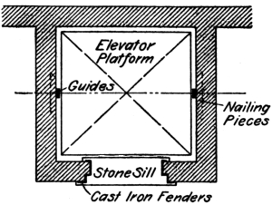
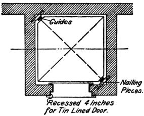
15. Freight Elevators.—Freight elevators are either corner-guided or side-guided, the preference being for the latter, as they are more easily constructed and adjusted, and during the construction of the elevator shaft it is usual to build into the brickwork blocks of wood about the thickness of a brick and of sufficient length for the attachment of the guides. These are cut wedge-shaped on the ends, so as to hold more firmly in the brickwork. A diagrammatic plan of a side-guided and corner-guided elevator is illustrated in Fig. 4 (a) and (b), respectively.
Owing to the fact that it is necessary to have considerable hoisting mechanism, at the head of the elevator shaft, the shaft is extended above the roof, sometimes as much as 5 or 6 feet, for the minimum height from the elevator platform at the top floor level to the under side of the beams carrying the mechanism is about 16 feet, and the sheaves carrying the rope and other mechanism at the top of the shaft require several more feet.
16. Elevator-Shaft Windows.—Frequently, elevator shafts are lighted with windows. Where such windows open into the building, they must be constructed with metallic frame and wire glass; but where they open outside of the building it is not necessary to do this. Where elevator shafts are lighted from the top, metallic skylights glazed with heavy glass should be provided. It is not considered such good practice to use wired glass for this glazing, the idea being that in case of fire, as each floor is cut off from the elevator shaft with fireproof doors, vent may be had from the skylight at the top of the shaft when the glass is broken, and some of the municipal and state laws stipulate that the skylight at the top of an elevator shaft shall not be less than two-thirds the area of the shaft.
As there is some mechanism on the bottom of the elevator platform and at the foot of the shaft, it is necessary to sink the shaft at least 3 feet below the basement floor level, provided that the elevator runs to the basement floor.
TOILET ROOMS
17. Location of Toilet Rooms.—In designing factory buildings where a great many people are employed, the question of toilet accommodations is a very necessary consideration.
After the location of the toilet room has been decided on, and it should be placed as centrally as possible to the floor area, the number of closets should be determined. It is usually found sufficient accommodation if one closet is allowed for twenty people. In planning the toilet room, it is essential, and generally required by law, that the room shall be located on the outside wall, so that windows will open directly into it. If the partitions between the compartments only extend part way toward the ceiling, it is not necessary that each compartment of the toilet room containing a closet should have a window. For instance, referring to Fig. 5, which is a typical arrangement of factory toilets, it is necessary only to provide the window opening into the outside space surrounding the enclosures around the closets.
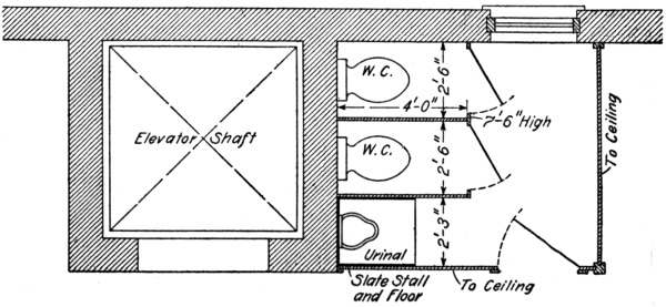
Fig. 5
18. Material Used for Partitions.—The partitions of both the compartments and the toilet room are, in factory construction, usually built of 1⅛-inch, yellow-pine, tongued-and-grooved, beaded ceiling, the corners of the partition being braced with 4" × 4" stop-chamfered yellow-pine posts rabbeted to receive the ceiling. In no instance should the partitions be constructed with an enclosed space or concealed work. For hygienic reasons, it is always advisable to provide toilet rooms with waterproof floors, and the brick walls that may partially surround the enclosure should be waterproofed for a distance of at least 1 foot from the floor. The waterproofing commonly employed for the floors is asphalt or asbestolin, the latter being a composition that is placed directly on the finished floor and forms a permanent covering about ¼ inch in thickness, and of the nature of the best cork linoleum.
In waterproofing the walls, about the only practical method to employ is to give them several coats of an approved waterproof paint.
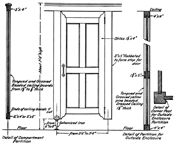
Fig. 6
Fig. 6 illustrates a reasonably cheap and still excellent construction for toilet-room enclosures, the several details of the construction being sufficiently clear without further explanation.
19. Toilet-Room Fixtures.—In selecting fixtures for the toilet rooms of a factory building, only the most serviceable kinds should be used. In standard work, iron-porcelain siphon-jet closets with overhead copper-lined flushing tanks are employed. The flushing is controlled automatically by the action of the seat, which is always raised by being provided with counterweights. Lids to the closets are never used in factory installation, from the fact that they are readily broken and generally out of order.
TYPES OF MILL CONSTRUCTION GIRDER AND PLANK-ON-EDGE CONSTRUCTION
20. In Fig. 7 is designated an economical type of mill construction, which is much in use. This construction is slow burning in every respect, and is exceedingly simple, withal being substantial and presenting a good appearance on the interior of the building. It will be observed that the column supports of the floor consist of yellow-pine posts, varying from 20 inches square to 8 or 10 inches square, the latter being used for the support of the roof. The drawing shows columns and wall construction suitable for a six- or seven-story factory building, and the size of post indicated in the basement is about the maximum.
The girders consist of 6" × 20" yellow-pine pieces bolted together with ¾-inch bolts, though it is suggested that ⅞-inch bolts would be preferable. The purpose in bolting up a girder in this way is that the thinner planks are much more readily obtainable, they are more likely to be thoroughly seasoned, and a girder built up in this manner is usually stronger than a solid beam, from the fact that there is less likelihood of hidden defects existing in the timber and much better stock can generally be obtained.
21. Post Caps and Base Plates.—These girders just described are supported on cast-iron post caps, similar to the Goetz-Mitchell construction. These post caps, where they support girders in one direction only, are usually known as two-way caps. If they support girders in two directions—that is, transverse and longitudinal—they are known as four-way caps. These caps are generally cast of ¾-inch metal, and the girders bear on them at least 4 inches.
For the basement columns, it is usual to provide a cast-iron base plate, as indicated at a. The timber column is sized into the socket of the base plate, and it is best to carry the top edge of the cap well above the floor, so that any moisture from leakage or in washing the floor will not be allowed to penetrate to the wood. Owing to the fact that this base plate must transmit the entire load on the column to the brick, it must be heavily webbed on the sides and corners, as indicated in the plan at b.
22. Concrete Footings.—It is usual in designing the foundations for mill buildings to use concrete footings, as indicated in the plan. It will be noticed in this particular instance, and it is the usual practice, that the concrete footings are 12 inches in thickness. When the footings are stepped, as indicated, under the wall of the building, each footing is made about 12 inches in thickness, with a projection of not more than 6 or 7 inches.
Section of finish flooring
Fig. 8
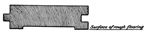
23. Floor Construction.—The floor construction of the building consists of 3" × 6" yellow-pine pieces, set on edge and spiked together. Such a construction as this is available for spans between girders of from 10 to 15 feet, and does away with all secondary girders, or beams. It also has an advantage in that it presents a neat ceiling beneath when the edges of the planks forming the rough flooring are beveled. On the top of this rough flooring, which is designed for carrying the floor load, and which is so constructed that the joints in the different pieces are broken, a 1-inch or 1¼-inch maple flooring is laid. Maple is used for finished floors in factories principally on account of its hardness and the excellent wearing surface that it affords. The maple flooring available in the market runs in lengths of from 3 to 16 feet, but the cost of the floor is greatly increased if a minimum length of 6 or 8 feet is specified. Usually the flooring is tongued and grooved and hollowed on the back, as indicated in Fig. 8. The hollow back prevents the flooring from curling. In a better class of finished flooring, the pieces are end-joined, or provided with a tongue and groove on the end. This prevents the end of the flooring from turning up and interfering with the smoothness of the floor and the operation of trucks over it.
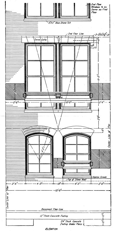
Fig. 9
24. Waterproofing and Dust Proofing.—For the purpose of deadening sound, and sometimes for the sake of waterproofing, sheathing paper or felt is inserted between the finished flooring and the rough plank. By the introduction of paper between the maple and the rough flooring, dust and dirt are prevented from falling through the crevices due to the shrinkage of the flooring boards above.
It is usual in finishing a floor around the edge to use about 2-inch quarter-round molding, as indicated at c, Fig. 7. This molding is also used around the wooden columns, or posts.
In order to prevent the posts from splintering at the corner, and so that there is less likelihood of the occupants being hurt, a stop-chamfer, or arris, is formed on the corner.
25. Splice Pieces.—There is one feature which must not be overlooked in mill construction, such as occurs in this figure, and that is that since the girders butt against the columns on top of the post caps, usually flush, there is nothing to carry the boards at d, therefore yellow-pine pieces or steel angles must be provided, as indicated at e. These splice pieces answer two purposes, namely, to form a bearing for the ends of the planks f, f, f, and also to tie the girders rigidly together longitudinally, and thus increase the rigidity of the floor construction.
For a similar reason, it is necessary to form a ledge, either by reducing the size of the pier above, or by corbeling out, at the window openings, as shown at g, for the support of the floor planks at h h. On the top of the corbel so formed, usually a 3" × 8" yellow-pine piece is securely anchored to the wall, to provide a bearing for the ends of the rough floor planking.
26. Reference to i and j, Fig. 7, shows that there is very little room between the head of the window and the bottom of the floor construction. By this means, the maximum amount of light near the ceiling is obtained, and, besides, the ventilation is greatly facilitated. This is one of the important features in factory designing, as well as in school-house architecture.
27. Foundation Walls and Piers.—From the section of the wall shown at k k, Fig. 7, it will be observed that the entire building is practically supported on heavy piers, and that the 13-inch walls below the window sills are only spandrel fillings. In some instances, 9-inch walls can be used in these places, but it is not considered advisable from the fact that beating rain will readily drive through a 9-inch wall, and, besides, there is hardly sufficient sill for a heavy window frame.
Attention is particularly called to the construction of the window sill at l. In the better class of construction, heavy bluestone sills 5½ in. × 7½ in. would be used; but for cheap work, it is customary to use a light 3" × 5" bluestone sill.
Where spandrel fillings more than 13 inches in thickness are used, or where the thickness of the wall is much greater than the frame, as indicated at m in the basement, beveled bricks on edge are used for forming the sloping wall inside. The purpose of the sloping sill is to prevent the corners from being broken and damaged, and employes from occupying them.
28. Terra-Cotta Window Heads.—In factory construction, the use of terra-cotta window heads is not unusual, and the construction of such a window head is indicated at n, Fig. 7. Where terra-cotta window heads are used in this manner, some means of support must be had for the brickwork above the window head, as terra cotta in itself is of little use as an arch, or lintel. It is not uncommon to use angle irons back to back, as indicated on the section of window head n. This construction, of course, can only be used where the wall runs parallel with the supporting floor, for if the head of the window receives beams or girders it must necessarily be more strongly and rigidly constructed with heavy channel irons, or I beams.
Where the windows of the basement, as shown at m, are brought down close to the pavement, it is absolutely necessary that the pavement be sloped away from these windows with considerable pitch, not less-than 1 inch in 1 foot, as otherwise the water is likely to lay against the window sill or run under it, causing it to rapidly decay, the capillary attraction of the window frame drawing up the water.
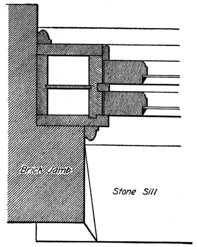
Fig. 10
29. Window Openings.—Referring to Fig. 9, which shows the face view of a bay of the wall illustrated in section in Fig. 7, the details of the several window openings in the walls may be studied. The basement windows are independent frames with double-hung sash, a rowlock brick arch supporting the brickwork over the window head. In the practice and design of window heads for mill buildings, it is usual to make the radius of the window head equal to the width of the reveal. In this instance, the distance across the opening is 4 feet 3 inches, and the radius of the arched head is the same dimension.
The windows throughout the balance of the building are twin windows, double hung, and the construction of the window frame and sash is shown in the drawing. This frame is what is known as a reveal frame, and is built in as the brickwork progresses. Sometimes the frame is slipped in from the back, as shown in Fig. 10, and when this is the case the work can be carried along without waiting for the window frames.
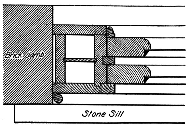
Fig. 11
As distinguishable from the reveal frame, there is the plank-frame construction, which is not built into the brickwork, but is built up as shown in Fig. 11. When it is desirable to have the central mullion a, Fig. 9, as narrow as possible, the box construction indicated on the drawing is done away with and the window is hung by means of overhead pulleys, the weights operating in the boxes at the sides.
STANDARD SLOW-BURNING CONSTRUCTION
30. A type of factory construction more usual than that previously described is illustrated in Fig. 12. In this illustration, it will be noticed that the main girders bear on wall pilasters, and the spandrel filling between the pilasters is kept as thin as possible. The usual reveal window frame is used, as shown at a, and the soffit of the arch over the window openings is checked at the head of the opening to provide a wind and water stop as at b. In this construction, which is probably the best, though it does not possess the advantage of giving the maximum amount of window space, and, consequently, light in the building, a rowlock or bonded brick arch is used over the window frames. By means of this construction, either the window frame may be built in place, or the windows may be slipped in from the back against a rabbet formed in the brickwork. The arch over the window head is indicated at c.
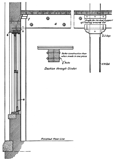
Fig. 12
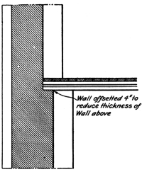
Fig. 13
31. Floor Construction.—The floor construction consists of heavy timber girders, no dimension of which may be less than 6 inches, as otherwise it would not comply with the requirements of slow-burning construction. The floor planking consists of 3- or 4-inch tongued-and-grooved spruce, or yellow-pine planking, planed on the under side, and thoroughly spiked to the girder. Planking of the former thickness may be used for clear spans as great as 8 feet, while the latter thickness may be used for up to 10-foot or even 12-foot spans, if the loads are light. The girders are indicated at d, and the floor planking at e. Usually the girders, in order to obtain the requisite strength, are made of long-leaf yellow pine. On the top of the spruce planking is placed a finished maple floor. This floor is made from either 1-inch maple, which finishes as ⅞ inch, or 1¼-inch maple, which finishes as 1⅛ inches, in thickness. Neponsett sheathing paper, or deadening felt, is placed between the spruce planking and the finished maple flooring for the purpose of preventing dust from percolating through. This sheathing paper or felt is sometimes made waterproof to prevent leakage due to water used for fire-extinguishing purposes.
Frequently, the brickwork is corbeled out, as indicated at f, in order to form a fire-stop between floors, or at least to prevent an open joint at this place. Where the walls are offsetted, as shown in Fig. 13, there is no need of corbeling out, for the offset in the brickwork can be made to form the fire or dust stop.
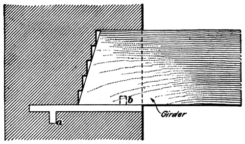
32. Where heavy yellow-pine girders bear on brick walls, it is usual to obtain the requisite bearing area by the use of cast-iron bearing plates, as indicated in Fig. 14 (a), (b), and (c). In (a) is shown an ordinary flat plate that has an area figured so that the load on the brickwork will not exceed its ultimate stress, which for brickwork laid in lime-and-cement mortar is about 150 pounds per square inch, while for brickwork laid in cement mortar, it is in the neighborhood of 200 pounds per square inch. This plate is usually cast with a lug on the back, as at a, to be built in the brickwork, and dowel-pins, or a lip, as at b, over which the girder is fitted, or notched. By this means, a tie to the wall is obtained. There is difficulty, however, in using such a connection, for the carpenters on the job frequently miscut their beams, so that the notchings or borings at b do not come where they should, and to remedy the defect, the notchings, or borings, are cut or gouged out, so that frequently the pin or lip at b is not brought to bear against the timber.
(a)
(b)
(c)
Fig. 14
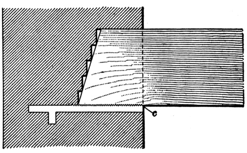
A more practicable bearing plate is illustrated in Fig. 14 (b). Here, instead of providing dowels, or a lip, to set into the girder, the top of the plate is cast with teeth, as indicated at c. While these teeth tend to destroy fibers at the bottom of the beam, they nevertheless sink into the timber, creating great friction, and thus accomplish a tie to the wall fully as efficient as a dowel-pin, or lip, let into the timber would be.
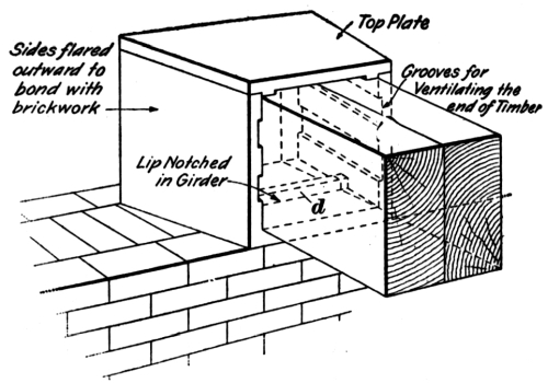
Probably the most common form of bearing plate is that illustrated in Fig. 14 (c), which is known as the Goetz-Mitchell bearing box. This is usually built flared, as indicated in the illustration, so that when built into the brickwork it will have a hold in it, and the timber acts as a tie by being notched over the lip, as at d in this figure. These Goetz-Mitchell boxes are generally provided with a plate that sets on top of them, on which the brickwork may be built, and not infrequently the sides of the boxes are grooved so that the ends of the girders are ventilated.
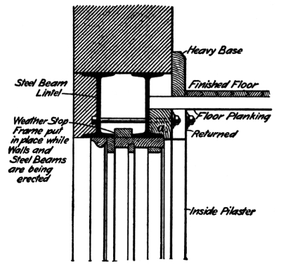
Fig. 15
33. Window Heads.—In Fig. 12 was shown a form of window head that is the best for strength, but possesses the disadvantage of lowering the top of the window, thus cutting off light to the room, which is a serious objection where the room is wide, or where it depends on the windows in one side for lighting the entire floor area. In order to keep the window head up near the under side of the floor construction, an I beam, lintel, or some similar form of support for the brickwork over the head that takes up little room, must be employed. A construction using shallow I beams is illustrated in Fig. 15. Here the window head is directly beneath the rough flooring; and while the outside face of the window is formed with an arch, the brickwork above the window head is supported on shallow I beams. This figure illustrates a section through the wall extending parallel with the main girders, a bearing being obtained for the floor planking by bolting to the I beams a bearing strap a.
This construction would not be permitted in some of the larger cities, as the building laws require that all steel beams supporting brickwork must be fireproofed. Consequently, a steel lintel of this construction would have to be surrounded with concrete, and the window head dropped somewhat to allow a bearing for the floor planking, or some other form of construction adopted.
FACTORY BUILDINGS OF REINFORCED CONCRETE
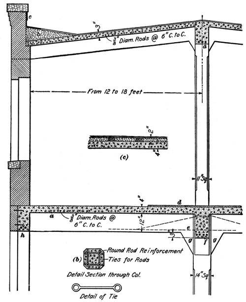
Fig. 16
34. Within the last few years, the cost of the best Portland cement has been so materially reduced that concrete has become an available material for the construction of factories. Unless used in great masses, however, it has not the strength to support the necessary floor loads without the use of steel reinforcement. As explained in Design of Beams, the fibers on the bottom of all beams subjected to transverse stress are in tension, and while concrete has considerable resistance to compression, it offers comparatively little to tensile stress. It is therefore necessary to reinforce the lower portion of all beams and floor slabs as indicated at a, Fig. 16.
35. Advantages of Reinforced Concrete.—In Fig. 16, the details of a typical reinforced-concrete factory building are illustrated, and a building of this character may be constructed for a cost of from 10 to 15 per cent. greater than the ordinary slow-burning type of building. Besides, this construction possesses the advantage of being practicable for long spans and heavy loads, whereas in buildings of the slow-burning type, owing to the fact that the size of the wooden beams is limited to the available commercial timber, it is frequently impossible to design floors with girders of large spans for floor loads of over 250 pounds per square foot. While this is a heavy load, it is too light for some classes of work, such as occur in printing houses and lithographing establishments where heavy stones are used and stored. The floor loads in such buildings sometimes amount to as much as 300 or 400 pounds per square foot, while it is not unusual to find the load on floors in warehouses amounting to as much as 500 pounds per square foot.
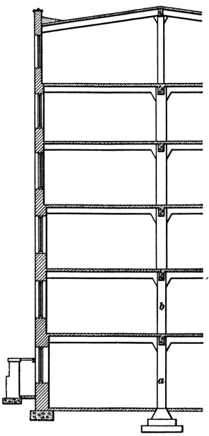
Fig. 17
36. Strength of Concrete Columns With Steel Cores.—In the building shown in Fig. 17, it will be noticed that the columns are reduced in size in the lower floors, increased in the middle portion of the building, and reduced toward the roof. The reduction in the columns a and b is due to the fact that these columns are reinforced with a steel core composed of structural shapes riveted together, angles usually being employed for this purpose. In proportioning such columns, it is good practice to figure on the ultimate safe unit compressive stress of the steel without considering the reduction made by the usual column formula, but to neglect, in the consideration of the strength of the column, the resistance of the concrete surrounding the steel core. To illustrate, if the sectional area of the steel reinforcements in these columns equals 20 square inches, and a safe unit fiber stress of 16,000 pounds is assumed, the safe strength of the column will be 320,000 pounds.
Above the second floor, the columns are made much larger, for here there is less steel reinforcement, and it is necessary to figure on the safe bearing strength of the concrete.
37. Strength of Reinforced-Concrete Columns.—In proportioning reinforced-concrete columns, it is customary among conservative engineers to figure the safe strength of the concrete-column section at 500 pounds per square inch of section; that is, if the column is 20 inches square, its area is 400 square inches, and its safe strength at 500 pounds per square inch will be 200,000 pounds. In the top floor, it is seldom advisable to use concrete columns less than 10 inches square, though at this dimension they generally possess several times the requisite amount of resistance.
All columns in reinforced construction generally have embedded in them 3¾-inch to 1-inch round steel rods, tied together with round iron binders, or bar-iron straps as indicated in Fig. 16 (b).
38. Floor and Roof Construction.—In considering the floor and roof construction of buildings built of reinforced concrete, it will be noted from Fig. 16 that the roof slab is made 3 inches in thickness. Such a slab made of good concrete, reinforced with ⅜-inch steel rods, spaced 6 inches from center to center, will carry the usual roof loads for spans up to 7 feet in the clear.
In forming the gutter for such roofs, as indicated at b, the gusset is made by filling in with cinder concrete. Usually cast-iron eave boxes are embedded in the concrete, and these in turn connected with inside rain conductors.
The beams supporting the roof, when the span is from 12 to 14 feet, are made about 12 inches deep and 8 inches wide, while the girders, also constructed of reinforced concrete, are usually made about 3 inches deeper and 11 inches in width.
In order to make the roof impervious to moisture, a covering of felt and slag is commonly employed. This slag joins the parapet wall with the usual tin flashing and counter flashing, as at c, though copper is recommended for best work.
In the floor construction of reinforced-concrete factory buildings, the slabs forming the floor panels are made not less than 4 inches in thickness, and seldom over 5 inches, with a 1-inch finish coat of cement besides, if this character of finish is desired. Such a floor slab is shown in the construction at d, Fig. 16, while the wooden floor construction is shown in Fig. 16 (c). Here the structural feature of the floor is a 4-inch concrete slab upon the top of which is placed 2" × 3" beveled hemlock sleepers, the space between these sleepers being filled with cinder concrete, and the floor finish obtained by laying 1-inch tongued-and-grooved maple floorings.
39. Reinforced-Concrete Beams and Girders.—The depth of the beams and girders in reinforced-concrete construction varies, of course, with the span and loads to be supported. Their width enters little into the strength, and they may be made as narrow as possible in order to cover the reinforcing steel. It is the best practice to make beams and girders of the same width, for then the process of forming the molds is greatly simplified and the cost reduced.
In placing the reinforcement in the concrete, it should always be at least 2 inches from the outside surface, for a distance less than this is considered inadequate fireproofing. In order that the reinforcing metal e, Fig. 16, may enter over the top of the reinforcing metal at f, it is usual to make the secondary girders, or beams, 3 inches less in depth than the main girders. To stiffen the building, brackets are customarily introduced between the column and girders, as illustrated at g. These brackets tend to greatly increase the rigidity of the connection and shorten the span of the girder somewhat.
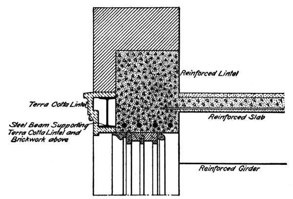
Fig. 18
40. Construction at Window Heads.—Where it is necessary to have the window head near the top of the ceiling, reinforced-concrete construction lends itself readily to the requirements of this condition, for even where girders are supported over the window head, the construction may be followed out, as indicated at h, Fig. 16. Where it is desired to have the window head raised still higher, a construction similar to that shown in Fig. 18 may be used. In this case, however, care must be taken to have the girders bear on the piers between the windows, and to have no intermediate beams.
(a)
(b)
Fig. 19
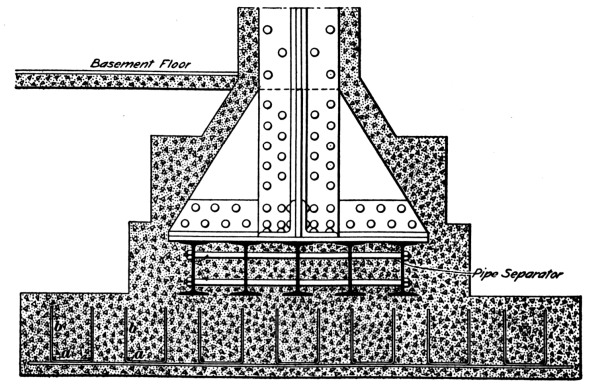
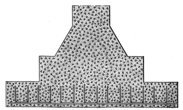
41. Column Footings.—With factory buildings of more than five or six stories in height, great pressure is transmitted to the soil from the base of the bottom column, and as it is necessary with soils of even fairly good bearing capacity to have footings beneath the piers supporting columns of from 6 to 10 feet square, adequate means of providing these footings must be obtained. In Fig. 19 (a) and (b) are shown two types of footings for concrete columns. In (a) is indicated a reinforced-concrete column with a steel core. In such an instance, all the load is transmitted by the steel core through its angle plates and webbing at the foot to grillage beams. These grillage beams are, however, not made sufficiently large to transmit the load to the soil, but merely to distribute the load on the bed of concrete. The spread portion of the footing is reinforced with steel rods a, a crossed each way, and longitudinal shear is taken up in the footing by means of stirrups b b. This is the usual type of footing construction under reinforced-concrete factory columns.
Where, however, the column is not reinforced with a steel core, but is merely a pier, footings may be designed as illustrated in Fig. 19 (b). Here the base of the column is enlarged in order to better distribute the load on the several steps of the footing, and where the bottom step has a considerable overhang, it is reinforced with steel rods and stirrups, as indicated.
42. Detail of Slab and Girder Reinforcement.—In the previous article, the general construction of the floors and column supports of a factory building was explained. By referring to Fig. 20, it will be shown how the girders and beams are reinforced with the steel bars. In this figure, a plan is indicated at (a) and an elevation at (b). The rod reinforcement of the slab is shown in the plan at a, a. It will be noticed that over every other beam these rod reinforcements lap, or break joints, and that some additional tie or reinforcement is placed over the girders, as indicated by b, b. These latter rods tend to tie in the floor slabs still more rigidly than can be accomplished with their individual reinforcement.
Referring to the elevation (b), it will be noticed that all the reinforcement of the beams is not usually carried along the lower portion of the girder for its entire distance, but that some of the reinforcement is bent up at a point about one-quarter of the span from the abutment, in the form of a camber rod. By arranging the reinforcing rods in this manner, an additional stirrup action, or tie, to the girder supports is provided, and the oblique section made by a horizontal line passing through these rods tends to provide additional resistance to the horizontal shear in the beams and also provide for negative bending moment produced in the beams near the support. To further provide for this, shear stirrups are placed closer together, toward the abutments, as indicated at c, c. These stirrups are ordinarily light pieces of bar iron bent in a U-shape, and sometimes bent around the rod reinforcement, a detail of this stirrup being shown in Fig. 20 (c).
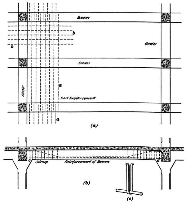
Fig. 20
STEEL-FRAME MILL BUILDINGS
43. There is a type of building which, while not distinctly mill construction as usually understood, is frequently used for one-story buildings, such as rolling mills, cement works, machine shops, foundries, rail yards, and buildings of this class.
The essential feature of these buildings is a steel-roof truss supported on steel columns, the columns being braced both to the truss and longitudinally of the building. It is usually the purpose in the design of such buildings to neglect everything but the necessary stability and the first cost. The steelwork, consequently, is of the lightest possible construction, usually designed for a unit fiber stress of from 18,000 to 20,000 pounds, and the covering of the sides of the building, together with window details, etc., is made only sufficiently good to keep out the weather.
44. Material for Roof Covering.—The roof covering of this class of building is either of slag on 2-inch spruce plank, spiked to nailing strips bolted on to steel purlins from beneath, with lagscrews, or of slate laid on 1-inch or 2-inch sheathing boards. Even galvanized iron is used for the roofing of some of the cheapest class of buildings, especially those which, owing to the process of manufacture, are subjected to a high temperature.
45. Construction of Sides of Building.—The sides of these buildings may be covered with either expanded-metal lath on metallic furring strips, plastered inside and out with cement mortar so as to form a fireproof and rigid screen wall about 2 inches in thickness; or, the walls may be 9-inch or 13-inch brick walls built part way up the height of the columns and leaving the columns exposed on the face; or, corrugated galvanized iron lapped 6 inches and secured either by riveting to metallic supports or nailed to wooden studding secured to the steel frames. Of these constructions, probably the first is the most expensive and also the most satisfactory.
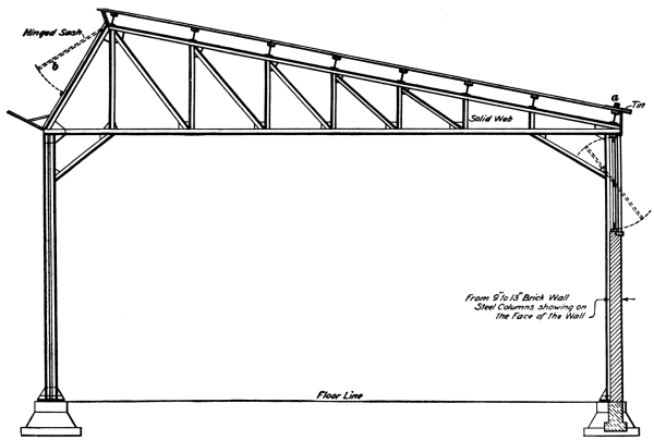
Fig. 21
46. Partially Supported Steel-Frame Building.— In Fig. 21, there is designated a type of construction that may be built for about $1 per square foot of the area covered. This consists of steel I beams, or angle-and-plate columns, used for column supports carrying the usual angle iron steel-roof truss. The roof is sheathed with 2-inch spruce tongued-and-grooved planking, covered with a good quality of roofing felt and slag, with a stop-gutter a at the edge. Owing to the fact that the steel columns are supported in a direction of their minimum radius of gyration by means of the brick walls, they can be made very light. The building illustrated has what is known as a saw-tooth roof. By this means, light is obtained on the side next to an adjacent and higher building by means of a sash b. This sash is usually made hinged or pivoted, to provide the necessary ventilation.
47. In Fig. 22, there is illustrated, diagrammatically, the framework of a one-story skeleton-construction building. In the design of all such buildings, where there are no end gable walls, the several columns and trusses must be braced diagonally, as indicated at a, a, and frequently it is necessary to introduce a secondary system of horizontal bracing from one panel point on the lower chord to another, as indicated at b, b.
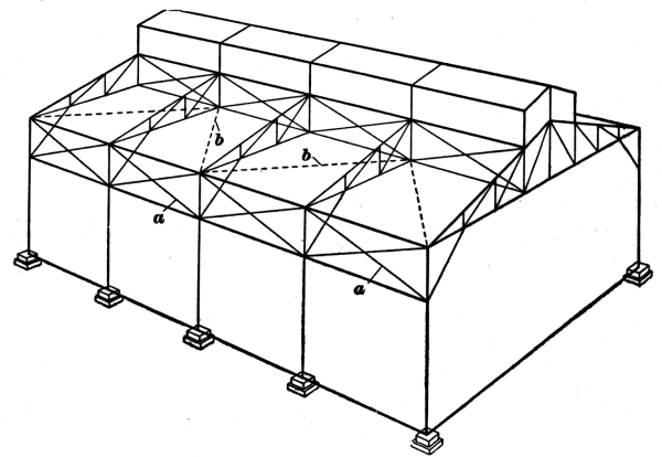
Fig. 22
In placing galvanized ironwork on the sides of steel-mill buildings, it is best to construct the necessary framework between the main supporting members of the building of light angles, or tees. These should be furnished punched with ⅜-inch or ⁵/₁₆-inch holes, to which the galvanized iron may be riveted, it being best to mark the galvanized iron in the field and punch it there. This may be done without much difficulty with the usual light gauge used for this purpose. It is sometimes necessary with this construction to flash around the window and door heads with IX tin.
DETAILS OF MILL CONSTRUCTION AND DESIGN
STRUCTURAL FEATURES
BEAM CONNECTION TO GIRDERS
48. In factory construction, the headroom is seldom available to support beams on the girders, as indicated in Fig. 23 (a). It is usually necessary, in order to cheapen the construction of mill buildings, to keep the distance between the clear headroom and the finished floor level to the very minimum, and consequently the tops of the beams are most always brought flush, or nearly so, with the top of the girder.
A common construction is to use some of the various forms of wrought-iron hangers, as shown in Fig. 23 (b). The type of hanger shown is a single stirrup, and is probably the best of any on the market; where beams enter the girder on both sides, the hanger is designed double. While it is popularly supposed that this hanger would readily fail by the bending of the metal at a, it is usually proportioned to safely carry any reaction imposed under ordinary floor loads. This hanger is obtained stamped out of steel plate or formed from bar iron.
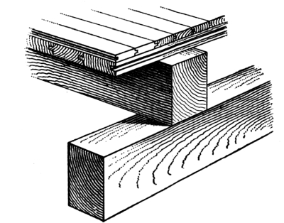
(a)
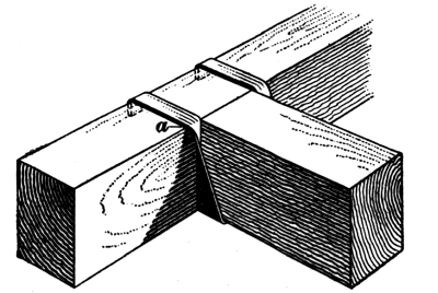
(b)
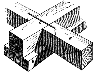
(c)
Fig. 23
49. Where it is not desirable to use wrought-iron or steel hangers, a simple and inexpensive form of construction may be adopted as that shown in Fig. 23 (c). Here the beam a is supported on a wooden strip b, which extends the full length of the girder, and is bolted near the bottom with through bolts. Such a construction provides sufficient strength for the support of the average factory floor, but its strength is difficult to figure with any degree of certainty, and some surer form of connection is generally considered preferable. In all instances, it is good practice to tie together the opposite floor-beams butting on a girder by means of an iron dog, or tie-plate, c.
50. In Fig. 24 (a), (b), (c), and (d) are indicated other methods of supporting the secondary floor-beams on main girders in the construction of factories. In Fig. 24 (a) is shown an I-beam girder supporting heavy timbers of a floor of slow-burning construction. It is always necessary in this construction to bring the top edge of the timbers above the upper flange of the I beam, and to span the space a thus created with a piece of timber for a tie and for the support of the floor planking. By providing this space between the ironwork and the wooden tie, any shrinkage that may occur in the secondary timbers will not cause the floor to ride on the top of the steel beam and thus make a ridge evident in the finished floor at this place. The timbers forming the secondary girders may either be supported on angle-iron brackets, or on angle irons extending the entire length of the girder. The latter method is only pursued when it is necessary to keep the end of the timber a few inches away from the steel beam, and the angle, consequently, being subjected to a greater bending moment, must have more resistance by increasing the width of the section of the bracket.
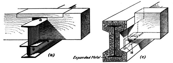
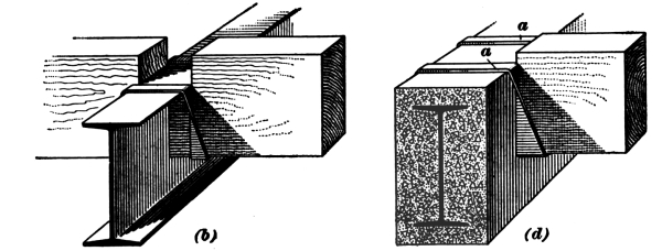
Fig. 24
Sometimes, the secondary beams are supported on double stirrup hangers, as shown in Fig. 24 (b). When it is not desired to use steel beams, resort is frequently had to flitch-plate girders. They are, however, held in some disfavor by the building departments of the several cities, who do not consider that the combined strength of the timber and metal can be taken, and will only permit the strength of either the timber or metal to be used.
51. The building departments of several of the large cities stipulate that buildings of the second class, which includes factory construction, shall not have steel girders that are not fireproofed supporting brick walls or floors. When this construction is required, the secondaries must be supported as in Fig. 24 (c). In this view is two angle brackets riveted or bolted to the steel beam, and extending through the concrete for the support of the wooden beams. While there is some danger of heat being transmitted to the beams through the projecting ends of these brackets, nevertheless it is considered better construction than that shown in Fig. 24 (d), where stirrups are used over the concrete fireproofing. In this latter construction, there is a liability of the stirrup bending at a, a, and crushing the concrete beneath. Where the reaction from the end of the girder is great, this undoubtedly is likely to occur, and such stirrups should be provided with a bearing plate on top of the concrete, so that their bearing at the edge will be distributed over a considerable area.
TRAVELING-CRANE LOADS
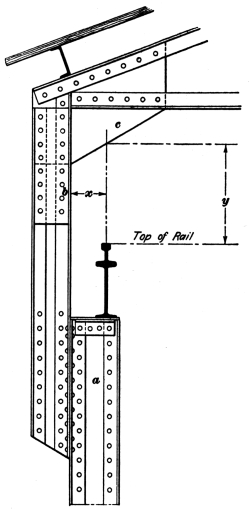
Fig. 25
52. Planning for Traveling Cranes.—In designing factories or mill buildings in which traveling cranes are to be installed, it is important to observe that the track of the crane can be properly supported, and also that there is sufficient headroom under the floor or roof construction to permit the trolley of the crane and the traveling mechanism of the crane girder to move underneath.
In Fig. 25, there is shown the upper portion of a steel-mill building. The columns a support the girder carrying the runway of the crane. A convenient means of supporting the roof is to splice to this column a similar column b, which is incorporated in the design of the roof truss and rigidly braced with the truss by means of a knee brace at c. In the design of such a building, it is very important to determine the distances x and y required by the makers of the traveling crane. These distances x, y depend on the size of the crane, that is, whether it is designed to carry 5, 10, 15, or more tons. Usually from 9 to 12 inches is sufficient for the measurement x, while the measurement y varies from 5 to 8 feet.
53. Cranes Supported on Reinforced-Concrete Walls.—Frequently, in the latest types of construction, the runway for the crane is supported on reinforced-concrete walls, which construction is shown in Fig. 26 (a). It will be observed that the pilasters supporting the crane are strongly reinforced in all directions from which stresses are likely to be created from the eccentric load imposed by the crane track.
Where cranes are supported on reinforced-concrete columns, as in Fig. 26 (b), it would be good practice to put additional rods in the far side of the column as at a, in order to supply a greater resistance to bending, and thus counteract the effect of the eccentric load produced by the reaction from the crane track. Where cranes handle heavy rails or cumbersome material that might, by swinging, impose a blow on the reinforced-concrete columns, it is good construction to protect the edge of the columns with an angle iron as indicated at b. This angle iron may be fastened in the forms and anchored by means of pronged anchors back into the concrete when it is tamped.
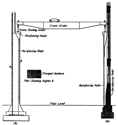
Fig. 26
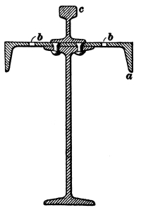
Fig. 27
54. Detail of Track Construction.—Many crane failures have been due to the spreading of the track between supports. It is better, therefore, to supply considerable lateral rigidity to the beam supporting the track or traveling crane. Where loads are heavy and plate girders are used for the runway tracks, the flanges of the girder are sufficient for this purpose. Where I beams are used, however, for the support of the crane track, it is good practice to place on the top of them and rivet with countersunk rivets, spaced about 18 inches apart on each flange, channel irons as indicated at a, Fig. 27. By means of these channel irons, which are drilled with open holes b b, the rail c may be readily clamped in place by means of wrought-iron clips and bolts, and the rails nicely aligned and adjusted by wedging between these clips and the track.
55. Maximum Stress on Track Girders.—The principal calculation for the construction of the runway of cranes exists in determining the maximum bending moment. The maximum bending moment on a runway girder occurs when the wheels of the traveling crane are in the position indicated in Fig. 28. It will be noticed that the center of the girder is midway between the center of the near wheel and the center of the crane trolley, that is, the distance a is one-half the distance b. The following formula will give the maximum bending moment on a crane girder when the load is in the position indicated in Fig. 28:
M = w(l - a)²
2l
in which M = bending moment, in inch-pounds;
w = load on one wheel of crane, in pounds;
l = span of girder from center to
center of support, in inches;
a = distance, in inches, marked in Fig. 28.
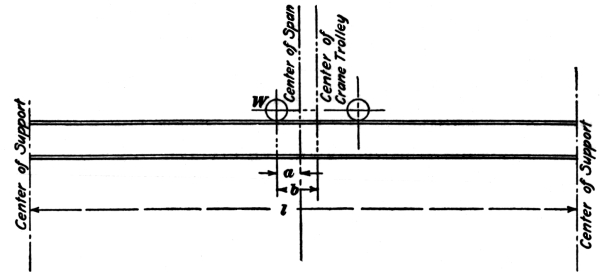
Fig. 28
In order to illustrate the application of this formula, assume that the wheel load w equals 10,000 pounds; that the distance from center to center of supports of the runway girder is 15 feet, or 180 inches; and that the distance a is 12 inches. By substitution,
M = 10,000 × (180-12)² = 784,000 inch-pounds
2 × 180
From this bending moment may be found, by the methods given in Design of Beams, the proper size girder to use.
THE POWER PLANT
BOILER ROOM
56. Locating the Boiler Room.—The ideal location for the boilers of a factory or an industrial plant is in a separate building, which may be denominated as the power house, and which may include as well, the installation of the engines, dynamos, and other machinery necessary for the generation of power and its transmission. More frequently, however, the ground is not available for the erection of a separate building for the power plant, and it becomes necessary to install the boilers and engines in the factory itself. The location usually selected for these vital features of the mill is the basement, and the arrangement of the boilers and engines must be carefully considered in the designing of this portion of the building.
57. In laying off the space to be occupied by the boilers, the probable growth of the manufactory must be provided for by arranging ample space for the installation of additional boilers.
It is best in arranging the boilers, to face them toward the available coal supply, which is usually a coal bunker, vault, or bin, but in no instance must the front of the boiler be nearer to a wall than the length of the boiler tubes, unless special arrangements are made, for this distance must be allowed in order to draw any defective or damaged tubes and replace them with new ones. Also, by arranging the boilers thus, the fireman has a minimum amount of carriage for the coal.
58. Coal Storage.—In designing the coal vaults, or coal storage, their contents should be figured to allow for 1 or 2 weeks’ coal supply, and as much more as is possible, to carry the plant over periods of existing coal shortage due to strikes or interrupted traffic from bad weather or other cause. In calculating the amount of space required for coal storage, it is sufficient to multiply the number of horsepower generated by the boilers by 4, which is the approximate number of pounds of coal per hour for the generation of 1 horsepower. This result, again multiplied by the number of hours for which the boilers are run at their capacity, will give the quantity of coal needed per day, in pounds. The weight per cubic foot of coal varies from 80 pounds for soft coal to 90 pounds for hard coal, so that by dividing the number of pounds by these quantities the cubic feet of coal required per day is obtained. The bins may then be proportioned for the number of days’ supply which the judgment of the designer may assume as being necessary.
59. Ash Disposal.—Besides the consideration of the coal supply, some disposition must be made of the ashes from the boilers. Frequently, a bin is constructed of masonry, alongside of the coal supply, into which the ashes are dumped by means of barrows. In large plants, this bin can be emptied by means of an ash conveyor, or elevator, which will carry the ashes to the level of the street or railroad track and thence into a cart or car.
60. Planning the Boiler Room.—In locating the boilers in the boiler room, which should be done in the plans of the building, for it is not customary to cement the floor space covered by the boilers, and the cost of the building is thus reduced, a passageway not under 3 feet, and better 4 feet, should be left back of the boilers. This passageway is required in order to have access to the clean-out doors and the blow-off cocks. The ordinary horizontal return-tubular boiler, and some water-tube boilers, can be constructed in a battery, with as many boilers as may be desired in a row, especially when the passageway is left back of the boilers. When setting other types of water-tube boilers, space should be left between each battery of two, for in these boilers, cast-iron doors are provided in the side walls for blowing the soot from the tubes, and access must be had through the side walls of the boiler for this purpose. It is therefore necessary in laying out the boiler space for boilers of this character to provide a passageway on one side of each boiler. In Fig. 29, a battery of return-tubular boilers is indicated, showing the clean-out doors for taking away the accumulation of soot and ashes that might be back of the bridge wall, through a passageway at the rear of the boilers. Some water-tube boilers are set in batteries of two, as the Babcock & Wilcox water-tube, land-type boiler, which is provided with the necessary clean-out doors, and doors for blowing the soot off the tubes in the side wall.
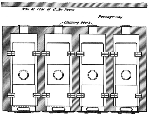
Front of Boilers
Fig. 29
It is therefore necessary in laying out the boiler room of a manufacturing plant to consider carefully the character of the steam generator and study its requirements, so that it may be successfully operated and the proper spaces allotted.
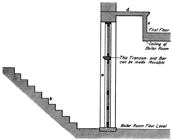
Fig. 30
61. Doorway to Engine and Boiler Room.—In the hasty design of buildings, it is frequently found that the size of the doorways is not sufficient to admit the boilers and machinery. This is a serious defect in the planning of a manufacturing plant, as it requires either the installation of the boilers and engines before the walls are entirely built, or else the tearing out of brickwork and jambs in order to accommodate them afterwards. An expedient for the enlargement of the headroom of doorways and openings into the boiler and engine rooms that are in the basement, is shown in Fig. 30. Here, if the lintel of the doorway a is kept below the floor level, where it would ordinarily exist, the headroom of the doorway will be materially reduced, and considerable difficulty will be encountered in taking any large piece of machinery, or a boiler or steam drum, down the steps b. The doorway is consequently increased in height by the introduction of the bulkhead at c; while by this means the floor space above is slightly reduced, yet use can frequently be found for the ledge or platform frame at the top of the bulkhead, as at d.
62. Floors Above Boilers.—It is important in designing boiler rooms in factories to have the floor construction over the top of the boiler of incombustible material, and it is customary in the better class of buildings to provide a section of fireproof floor over the top of the boiler room. This floor construction may either be a brick arch supported on steel beams, or hollow-tile construction, though reinforced concrete is now finding favor in this purpose.
63. It is not altogether necessary that the boilers in a building shall be placed in the basement, though as this is usually the least valuable of the floor space it is the practice to so locate them. In some electric-light stations, and in large factories, boilers have been located on the first floor, and even in several instances on the fifth and sixth floors. The exigencies that demand the latter installation, however, must be great, for it can be readily seen that much power must be expended in lifting the coal, etc. to the boiler room.
CHIMNEYS
64. Dimensions and Capacity of Chimneys. Nearly all the factory buildings combine in their structure a power plant, not the least important feature of which is the chimney. There are two things to consider in the design of a power chimney—first, its capacity for providing the necessary draft and the conduction of the requisite volume of gases from the furnace or boiler, and second, its stability. The first requirement regulates its diameter and height, and these dimensions, together with its construction, determine also its stability.
TABLE I
Diam- eter In. Height of Chimneys and Commercial Horsepower Capacity Side of Square Inches Effective Area Square Ft. Actual Area Square Ft.
50 Ft. 60 Ft. 70 Ft. 80 Ft. 90 Ft. 100 Ft. 110 Ft. 125 Ft. 150 Ft. 175 Ft. 200 Ft.
18 23 25 27 16 .97 1.77
21 35 38 41 19 1.47 2.41
24 49 54 58 62 22 2.08 3.14
27 65 72 78 83 87 24 2.78 3.98
30 84 92 100 107 113 119 27 3.58 4.91
33 105 115 125 133 141 149 30 4.48 5.94
36 128 141 152 163 173 182 191 32 5.47 7.07
39 154 168 183 196 208 219 229 35 6.57 8.30
42 182 200 216 231 245 258 271 288 38 7.76 9.62
48 269 290 311 330 348 365 389 43 10.44 12.57
54 348 376 402 427 449 472 503 551 48 13.51 15.90
60 436 471 503 536 565 593 632 692 748 54 16.98 19.64
66 579 620 658 694 728 776 849 918 981 59 20.83 23.76
72 698 746 792 835 876 934 1,023 1,105 1,181 64 25.08 28.27
78 885 949 990 1,038 1,107 1,212 1,310 1,400 70 29.73 33.18
84 1,035 1,098 1,157 1,214 1,294 1,418 1,531 1,637 75 34.76 38.48
90 1,269 1,338 1,403 1,496 1,639 1,770 1,893 80 40.19 44.18
96 1,532 1,606 1,712 1,876 2,027 2,167 86 46.01 50.27
100 1,760 1,865 2,043 2,197 2,359 89 50.11 54.54
104 1,899 2,024 2,218 2,395 2,560 93 54.39 59.00
108 2,051 2,190 2,399 2,591 2,770 96 58.83 63.62
112 2,323 2,588 2,795 2,983 100 63.46 68.42
118 2,632 2,883 3,114 3,339 105 70.71 75.94
120 2,725 2,986 3,225 3,447 107 73.22 78.54
124 2,915 3,193 3,449 3,687 110 78.31 83.86
130 3,165 3,467 3,745 4,004 116 85.04 90.76
136 3,868 4,178 4,466 121 94.85 100.88
142 4,305 4,567 4,886 126 103.69 109.98
150 4,719 5,097 5,448 133 115.72 122.72
Considering the first requirement, a circular flue is considered more efficient than a square one, because its inside surface offers less resistance to the passage of the gases, and there is not the likelihood of eddies being formed. There is much difference of opinion among engineers as to whether a stack should be narrower toward the top or increased in size. The practice is to taper a stack toward the top, this being done more on account of the necessity for increasing its stability than because of the draft. Some stacks have been built, however, with a larger inside diameter at the top than at the bottom, with the idea of providing a greater sectional area for the passage of the gases as their velocity is decreased. The capacity of the stack for carrying off the products of combustion depends on the temperature of the inside gases as compared with the temperature of the outside air. The average temperature in stacks for power purposes ranges from 450° to 600° F., and, therefore, as there is little difference in the travel of gases in flues between these temperatures, Table I can safely be used in determining the diameter and height of stack for a given capacity of power plant.
In Table I, it will be observed that the capacity of the stack is given in horsepower, and in calculating this table it was considered that 5 pounds of coal were burned to develop 1 horsepower, this being a high figure with the present economical systems of power generation. Allowance has also been made, in this table, for the friction of the gases against the side walls of the stack, it being considered that a 2-inch layer of dead air exists between the stack lining and the gases.
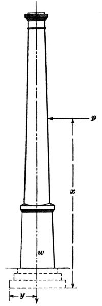
Fig. 31
65. Stability of Brick Chimneys.—In considering the stability of brick stacks, the overturning moment due to the wind must not exceed the resisting moment of the stack to overturning about the base. For instance, referring to Fig. 31, the pressure p due to the wind acts with the lever arm x about the base of the stack, tending to overturn it. The stack, or chimney, resists this overturning moment with its weight w, acting through a lever arm y; if these two moments are equal, the stack can be considered safe under the conditions considered, though it is better to have some factor of safety, 2 usually being sufficient. An easy formula by which to determine whether a stack is stable or not, is as follows:
w = (h² × dc)/b
in which w = weight of stack, in pounds; h = height of stack, in feet; d = mean diameter of stack, in feet; c = constant; b = width of base.
The constant c varies with the shape of the stack. For a square stack, when the wind is blowing at hurricane violence, 56 is used; for an octagonal stack, 35; and for a round stack, 28.
To demonstrate this formula, consider a square chimney having an average breadth of 8 feet and a width at base of 10 feet, the stack being 100 feet high. The problem is, therefore, to find what the weight of the stack must be in order to resist the greatest wind pressure likely to occur. By substitution, in the formula,
w = 100 × 100 × 8 × 56 = 448,000 pounds
10
With brickwork weighing about 120 pounds per cubic foot, the chimney in question must therefore have an average thickness of somewhat more than 13 inches.
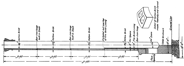
Fig. 32
66. A good rule to follow in designing brick stacks is to make the base at least one-tenth of the height. For stacks under 5 feet in diameter, the walls for the first 25 feet from the top may be 8 inches, increased 4½ inches for each additional 25 feet from the top. If the stack is more than 5 feet in diameter, the thickness at the top should be 1½ bricks, or 12 inches, with a 4½-inch increase for each 25 feet. If the stack is less than 3 feet in diameter, the brickwork for the first 10 feet from the top may be as little as 4½ inches; this thickness, however, is not recommended, as the weather is likely to penetrate such a thin wall, and sooner or later, together with the exposure to the gases, destroy the brickwork.
67. Construction of Brick Chimneys.—All brick stacks must be provided with a cast-iron or stone coping at the top, and it is usually well to tie them in toward the base with good heavy stone band courses. In constructing brick stacks, the brickwork should be laid up in lime-and-cement mortar, and the bricks well covered and slid in place, not just tapped or hit with the handle of a trowel.
All chimneys should also be provided, for a distance of at least one-third of their height from the base, with a fire-brick lining, laid up in fireclay, and at the bottom of this lining, where the flues from the boiler enter the stack, cast-iron cleaning doors and frame should be provided for removing soot that will accumulate and drop down. A good example of a brick stack is given in Fig. 32; this stack has a capacity of 500 horsepower, and is sufficiently stable to resist any wind pressure.
FIRE-PROTECTION OF MILL BUILDINGS
SPRINKLER SYSTEM
68. Sprinkler Tanks.—In the large cities, where fire risks are great, and where nearly all the buildings and their contents are protected by insurance, the owners of the buildings are subjected to the rules and regulations of the Underwriters, or Associations of Insurance Companies. These Underwriters from time to time pass regulations insisting on certain further precautions and protection against fire, such as the installation of sprinkler systems, stand pipes for hose attachment for each floor, etc.
As the available city pressure or water supply of the municipality may be limited, or uncertain, or the pressure too low for a high building, it is sometimes necessary to place water tanks of from 10,000 to 30,000 gallons capacity in towers on the roofs of factories, and in the design of new factories provision is usually made for three tanks.
In designing a building, these tanks are located at such a point that their support is insured by the walls beneath, and the most convenient place is found to be over the stair tower or adjacent to it. As 1 gallon of water, together with the tank containing it, has a unit weight of 8 pounds, a 30,000-gallon tank complete will weigh in the neighborhood of 240,000 pounds, which must be supported on the walls and by means of iron beams.
The architect, besides providing adequate support for these tanks, must so design the tanks as to secure them against bursting, which would lead to serious consequences. For durability, sprinkler or fire-protection tanks are made of either cypress or cedar from 2 to 3 inches in thickness. They are usually in the shape of a truncated cone, and the bottom of the tank is required to be at least 20 feet above the highest point of the top story.
The important feature in the design of such tanks is to see that they are properly braced with hoops, and it is usual to specify that no hoop shall be subjected to a unit stress of more than 12,000 pounds for iron and 16,000 pounds for steel. These hoops are made from ¾-inch to 1-inch round iron, not less than the former, and the required strength is obtained by spacing them closer together at the bottom and farther apart toward the top. They are held together with adjustable clamps, as indicated in Fig. 33, and by the use of such clamps they may be readily tightened. The bottom hoops of the tank are subjected to great stress, and it is good practice for these hoops to bear against a flat iron hoop, as indicated in Fig. 34. By this construction much greater bearing is provided on the wood, and the round iron is prevented from cutting into the staves of the tank. In some instances flat iron hoops are used altogether, but it is considered better to use round iron hoops, from the fact that they are not likely to corrode through as rapidly as the thin flat iron.
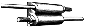
Fig. 33
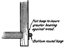
Fig. 34
69. Proportioning the Hoops.—The principal element of engineering entering into the design of large wooden water tanks consists in the proportioning of the hoops, and Table II will be found convenient in determining the hoops required for any size of tank.
70. In order to determine the number of hoops of a certain size required for any span of 12 inches at a point any distance from the water-line, the following formula may be used:
N = 5.16 d H
8
in which N = number of hoops required in 1 foot of height of tank; d = diameter of tank, in inches; H = height of water-line from center of space under consideration, in feet; S = actual safe strength, in pounds, of hoops assumed to be used.
This last value may be found from Table II.
TABLE II
SAFE STRENGTH OF ROUND TANK HOOPS
Diameter Inch Steel Pounds Wrought Iron Pounds
⅝ 3,232 2,424
¾ 4,832 3,624
⅞ 6,720 5,040
1 8,800 6,600
71. To illustrate the foregoing, assume that it is desired to find what will be the spacing of ⅞-inch steel hoops at the bottom of a tank 12 feet in diameter, in which the water-line is 16 feet from the middle of the section under consideration. Applying the formula in Art. 70, using in conjunction therewith Table II, it is found that
N = 5.16 × 144 × 16 = 1.77.
6,720
This result, 1.77, is the number of hoops required in 12 inches of height from the bottom of the tank, and would indicate that the hoops should be spaced about 7 inches from center to center, for 12 inches divided by 1.77 gives approximately 7 inches, the pitch of the hoops. This process should be repeated for different points throughout the height of the tank, and from the results the tank may be designed.
72. In the installation of sprinkler tanks, it must be observed that they are placed some distance above the highest point of the top floor, the distance usually required by the Underwriters being 20 feet, if it is possible of attainment. The tank should always be roofed, have a ladder from the roof of the building to its top, and a steam pipe inside to prevent the water from freezing in winter. This pipe is furnished with a check-valve to prevent the water in the tank from siphoning.
EXAMPLE FOR PRACTICE
What should be the spacing of the ¾-inch round wrought-iron hoops on a tank 10 feet in diameter and 12 feet high at a distance of 6 feet from the water-line?
Ans. 12 in.
73. Automatic Sprinkler System.—The sprinkler system as now installed for protection against fire in the interior of a building consists essentially of piping connected to a gravity tank and extending over the entire ceiling by means of mains and branches. There is located on the ends of the branches automatic valves or stops, which are collapsed or opened by the melting of a fuse or solder at a temperature more than is likely to exist in the room at any time and still below that which would be created by an incipient fire.
74. The underlying principles of automatic sprinkler systems as stated by the Underwriters are as follows:
1. Buildings must be open in construction, free from concealed spaces, or places where water thrown from sprinklers cannot penetrate.
2. Sprinklers to be so located that their distribution will cover all parts of the premises.
3. Sprinkler piping to be of sufficient capacity and to have water under pressure in same at all times, except in case of a system where freezing is likely to occur, where an air lock is used.
4. An automatic supply of water of sufficient quantity and pressure available at all times.
5. Systematic, thorough, and intelligent care and inspection of the system.
75. Fireproof Windows.—It is frequently necessary, and in many cases required by law, and especially recommended by the Underwriters, to provide fireproof window frames and sash in walls exposed to great fire risk, or where it is necessary to admit light into elevator shafts or fire-towers. To meet this demand, several forms of metallic window frames and sashes have been evolved, and these sashes when intended as a fire-retarder are always glazed with wired glass.
76. Wired Glass.—The wire glass now in common use consists of heavy glass plate with wire mesh embedded in it. This glass is obtainable in polished, ribbed, prism, or mazed form, as shown in Fig. 35 (a), (b), (c), and (d), respectively. The plain glass, Fig. 35 (a), is used where the light is ample, and where it is desired for the occupants to see through the windows. The ribbed is employed usually in factories, and the ribs are generally run in a horizontal direction, so as to throw the light toward the ceiling and floor, thus diffusing it throughout the building. The prism glass is also employed in order to secure a greater diffusion of the light than is possible with the plain or factory ribbed glass, while the mazed glass finds favor where it is necessary to employ an obscured sash, which will still admit plenty of light and present a good appearance but yet cannot be seen through.
The glass used in metallic frames should not be less than ½ inch, or, if polished, ⁵/₁₆-inch, and the embedded wire should not have a mesh larger than 1 inch and should not be less in size than No. 22 Brown & Sharpe wire gauge, which is the standard used in America.
Fig. 35
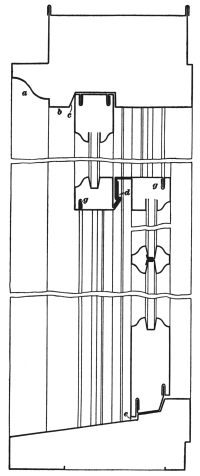
Fig. 36
77. Design of Sash.—In designing a sash for fire-retarder frames, it is necessary, in order to comply with the Underwriters rules and regulations, to observe that no single light exceeds 24 in. × 30 in. The metallic frames are generally constructed of No. 22 galvanized steel, while the sash are made of a lighter weight, generally No. 24. In unusual localities, where the frames are likely to be subjected to the influence of gases, with known affinity for iron or galvanizing, it is permissible to make the metallic frames of 18-ounce copper, though such frames are not considered the equivalent of an iron frame as a fire-retarder, and such frames should never be used in elevator, vent shafts, or fire-retarder partitions that are liable to intense internal fires.
In order to better explain the construction of the commercial frames, Fig. 36 is given, which illustrates one of the best frames in the market. In the figure, a vertical cross-section through the window-head sill and parting rail is illustrated. It will be observed that these frames can be neatly framed with architrave mold and stop, as designated at a and b. It will also be observed that the head for the top sash is beveled, as indicated at c, so that a tight joint is insured by the edge of the sash coming in contact with the bevel, and thus compelling a close connection. The parting rails are also constructed with a straight piece entering on a bevel d, so that at this point a tight joint is also secured. By the several offsets in the sill, wind and rain stops are provided, as indicated at e. Sashes constructed in this manner can be made to slide freely, noiselessly, and be made tight against weather and wind, as well as being secured against annoying clattering, or rattling. The sills of metallic frames are generally filled with cement, and sometimes the heads are similarly made solid. Any unusually large surfaces, like that which would occur between twin or triple windows, in the mullion, are securely braced inside with galvanized sheet iron or bar iron.
78. In the construction of metallic sash, solder is never used for holding the parts together, for all parts must be either lock-seamed or riveted, the lock seams being illustrated at g, Fig. 36. Soldering may be used only to fill up the joints. The objection to a joint that is only soldered and not lock-seamed is that in a severe fire when the window is subjected to an intense heat, the joint is apt to open by the solder melting out. When the joint opens, flames may go through and the fire-stop will thus be soon destroyed.
In designing the frames, they should have at least a 4-inch lap on the brick reveal on the sides and head, and it is not uncommon to wind-stop the sill by extending upwards a piece of galvanized sheet iron. While such windows as those described will act as a fire-retarder and prevent flames from reaching apartments that they protect, even in cases of severe conflagrations, nevertheless the glass radiates considerable heat, and inflammable goods should not be stored too close to such windows. Neither is it particularly desirable to have window shades secured to the frames of metallic windows. Where the goods in a building are particularly inflammable, the liability to pile them too close to the sash should be entirely eliminated by using window guards, which would maintain such merchandise at a distance of 3 or 4 feet from the window.
79. Fire-Doors and Frames.—There is no more important feature in the design of a mill building than the tin-lined fire-doors and their attachment to the jambs. Every fault in their construction, as viewed by the Underwriters, is likely to cost the owner additional insurance.
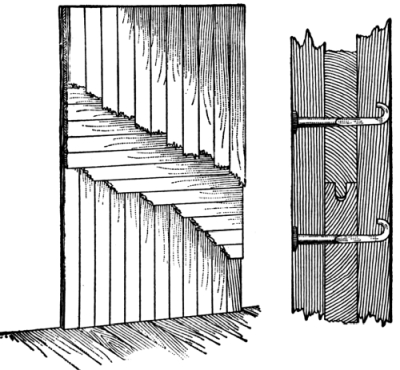
Fig. 37
Fig. 38
All tin-lined doors, when one door is used, should be made of three thicknesses of tongued-and-grooved planking, laid up and down and horizontally, and clinched-nailed, as illustrated in Fig. 37. The tin lining on these doors must be of IC tin, put together with locked seams, secretly nailed, and presenting the appearance designated in Fig. 38.
80. The sills of openings covered with tin-lined doors must always project under the door, so that there is no danger of burning through the floor and thus communicating to the space protected by this entrance. The several constructions of sills most commonly used are illustrated in Fig. 39.
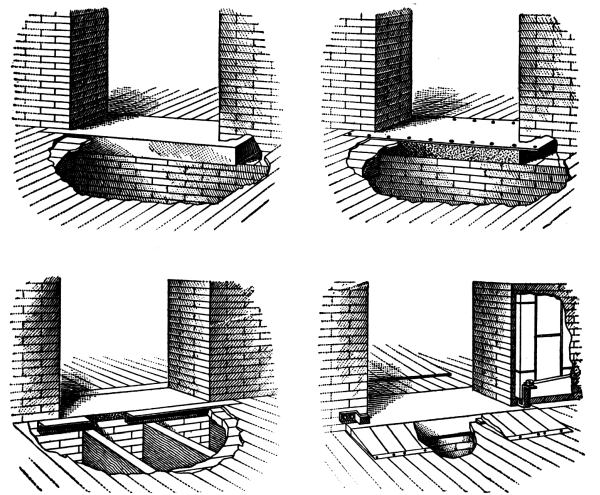
Fig. 39
81. Sliding-doors should be hung with anti-friction adjustable hangers. That is, the wheel of the hanger should have roller bearings for the axle, and there should be some means of adjusting the height of the door above the threshold by means of the hanger. The track for sliding-doors should be placed on a slant toward the opening, so that the door will automatically close. Where it is desired to have the door open, it may be held back by means of a chord, fusible link, and counterweight.
82. All folding doors should be heavily strap-hinged, and secured to the jambs with iron-hanging stiles and hinge eyes with through bolts, as shown at a, Fig. 40.
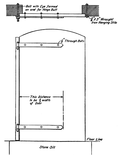
Fig. 40
Care must always be taken that any through bolts that go through brick walls near door openings, as the bolts shown at a, Fig. 40, be far enough away from the jambs so that there will be no danger of the bolts pulling through when put under strain. It is always better to build these bolts in the wall as the work progresses than to drill holes and put them in afterwards.