BUILDERS’ HARDWARE (continued 2)
Reading edition
56. Glass Knobs.—The most expensive knobs made are those of cut glass with metal mountings. Several knobs of this kind are illustrated in Fig. 62. Cut-glass or crystal-glass knobs are very costly, the price depending on the style and the amount of cutting required and on the grade of glass used. The new method of mounting glass knobs allows for adjusting the knobs to doors of varying thicknesses, and also gives the knobs a handsome appearance, making them both durable and reliable.
57. Styles and Sizes of Knobs.—The pottery knobs, such as the mineral, jet, and porcelain knobs, are made only in spheroidal and oval shapes. The spheroidal knobs are 2¼ inches in diameter, and the oval knobs 2½ in. × 1¾ in.
Cast-iron and stamped-steel knobs are made spheroidal and of the box pattern, with plain and molded edges, both styles of knobs being about 2¼ inches in diameter.
Bronze and brass knobs are usually spheroidal or ball-shaped, and are 2¼ and 2½ inches in diameter. They are also made oval and egg-shaped, these latter styles being provided in two sizes, namely, 3 in. × 2 in. and 2½ in. × 1¾ in. The same general dimensions obtain for wooden and glass knobs.
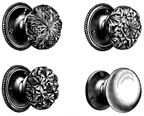
Fig. 62
58. Lock Spindles.—In supplying a pair of knobs, there is always included with them the spindle, which connects them and passes through the hub of the lock. The type of spindle generally used is the common, or side-screw, spindle, which is shown in Fig. 63. In this spindle, the knobs are secured by means of a knob screw passing through a hole in the knob and engaging with one of the threaded holes in the spindle. There are several holes in the spindle, so that the distance the knobs are apart may be adjusted properly. Should further adjustment be required, it is accomplished by placing thin washers at the end of the knob shank. This type of spindle is generally used with the cheap grades of trim, and should not be used in high-grade work.
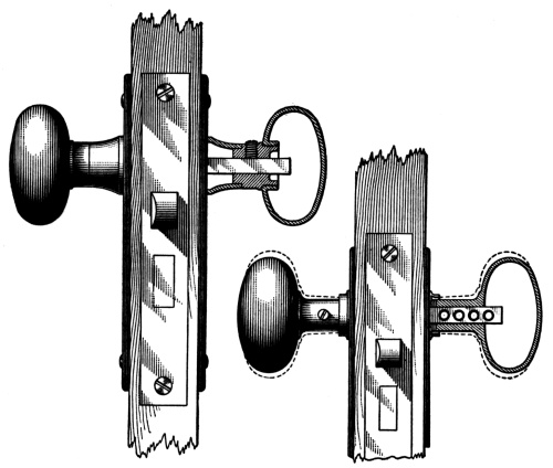
Fig. 63
There is a modern type of lock spindle, known as the “screwless” spindle, that permits the proper adjustment of the knobs without the use of washers and with less screws. These spindles overcome the general looseness and rattle found in the common type. A “screwless” spindle, known as the Triplex, is illustrated in Fig. 64. This spindle is a first-class device, and is constructed, as shown, of three parallel parts, triangular in section, which, together, form a square bar. To fasten the knob on this spindle, a setscrew in the knob bears on the center bar, and owing to their wedge form, the two side bars are forced apart and into frictional engagement with the spindle of the knob. The spindle itself is screwless, and there is nothing tending to loosen the setscrew, so that when once properly tightened, the knob will remain firm and in position on the spindle under all conditions of use. In some instances, this style of spindle has been condemned by owners and architects. This has been due largely to the fact that the mechanic did not set the screw tight against the spindle, thus allowing the knob to be easily pulled off. This is often caused by not using a screwdriver that exactly fits the head of the screw. When the knobs are put in place as they should be, this device always gives entire satisfaction.
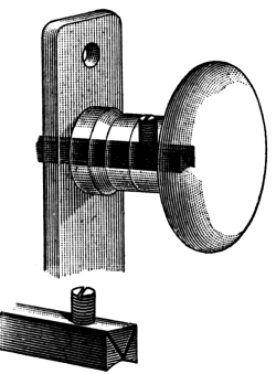
Fig. 64
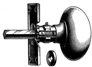
Fig. 65
There is another, though somewhat costly, type in the market, known as the wrench spindle. This spindle is illustrated in Fig. 65. As shown, the mechanism consists of a chuck, or vise-like arrangement, formed on the knob shank. When the nut a is screwed on the jaws b, the tendency is to grip the spindle securely, the latter being solid and without screw holes. This type of spindle allows perfect adjustment.
Another type of knob spindle is the swivel spindle. This is used with front, vestibule, and other door locks that have stop-work, whereby the outside knob may be made operative or not, as desired. In order to accomplish this, the spindle is divided longitudinally, so that one end may rotate independently of the other.
The standard sizes of spindles for door locks, etc. are ₅/₁₆ and ⅜ inch square. Occasionally, spindles as large as ½ inch square are used for large knobs or handles, such as would be used with massive lock trim. For thumb knobs and locks and latches of this character, spindles ¼ inch square are employed.
59. Key Tags for Hotel Use.—Considerable confusion is frequently created by hotel guests taking with them on departure the key to their rooms. Formerly, hotel managers sought to prevent this practice by attaching to each key a large tag of iron or brass, generally serrated on the edges and made so cumbersome as to practically preclude its being carried in the pocket. Subsequently, tags made of red fiber of large size became popular. The usual forms of these large tags, whether of brass or fiber, are illustrated in Fig. 66. The use of key tags, however, is gradually being superseded by having the name of the hotel and number of the room stamped plainly on the key bow, the stamped name of the house serving for its quick identification and return by mail. The latest and best development in this detail consists in attaching to the key bow, by means of a short chain, either an ornamental disk bearing the name of the hotel and the number of the room, or a small ball, the name and key number still being retained on the key bow. In either case, the short pendant serves for convenience in the use of the key, diminishes the danger of misplacing it, and, if well designed, contributes to its appearance.

Fig. 66
WINDOW SASH HARDWARE
SASH TRIM FOR DOUBLE-HUNG WINDOWS
60. Sash Pulleys.—The pulleys for the counterbalancing of double-hung, or sliding, windows, while apparently unimportant pieces of hardware, are worthy of much consideration in their selection, and in the preparation of the specifications care should be exercised to provide the best pulley consistent with the character of the work. It is good practice to furnish the millmen with a sample of the pulleys that are to be used, so that the frame will be properly mortised to receive them when the sash are hung. By this method, the necessity of exposing the case to the weather during the erection of the structure is obviated.
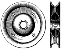
Fig. 67
The common grades of sash pulleys are rough and cheap, and may be used for unimportant work and light sashes. For heavier sashes and important work, however, a better grade of larger and heavier construction should be used. It is important in specifying sash pulleys to stipulate the size of the pulley and to specify the diameter of the axle; also to state whether brass or bronze wheels and bronze faces are desired. Pulleys are supplied in 1¾-, 2-, 2¼-, 2½-, and 3-inch diameters. The required diameter of the pulley is determined by the thickness of the pulley stile and the diameter of the sash weight required to balance the sash.
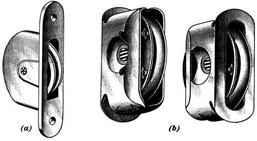
Fig. 68
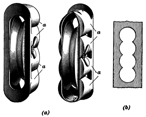
Fig. 69
The cases in which the pulleys are mounted in the cheaper grades are made of cast-iron, while in the better grades they are made of stamped metal. High-grade pulleys constructed of stamped metal are also provided; these are put together either by riveting the two faces of the pulley or by electrically welding them. The construction of a built-up steel pulley is illustrated in Fig. 67. The cases enclosing the pulleys are made of cast-iron, as illustrated in Fig. 68 (a), or they are constructed of stamped metal, as shown at (b). The ends of the facing of the case are made square, rounded, or auger-shaped, and are finished either rough, polished, or lacquered, or are faced with brass or bronze of any finish desired. The pulleys illustrated in Fig. 69 (a) are so constructed that the mortise in the frame may be readily formed by a special boring machine carrying three or four bits. This machine bores holes of a size to fit the several cylindrical portions of the stamped-metal case, as at a, a, a diagram of the mortising in the frame being illustrated at (b).
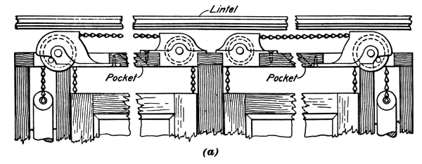
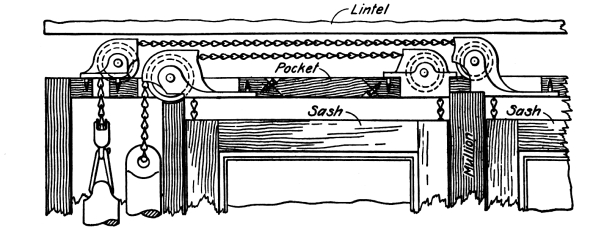
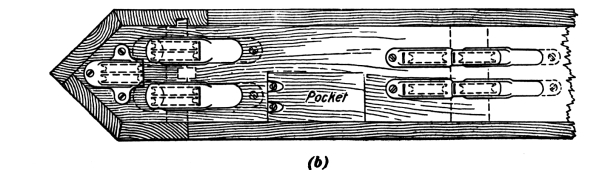
Fig. 70
The better grades of pulleys may be procured with semi-steel, brass, or bronze wheels, and with plain axles or with ball or roller bearings. In the cheaper grades of sash pulleys, the axles are formed of common wire, while in the better grades they are made of either steel or gun metal ⅜ inch in diameter. In the best pulleys, the wheels are turned, to insure smoothness of motion, and are made with grooves for cord, ribbon, or chain. All steel pulleys built up as illustrated in Fig. 67 are of recent invention; they run smoothly, and are very easily applied. These pulleys are also made with ball or roller bearings, and may be obtained at a reasonable price.
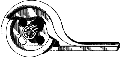
Fig. 71
There is a special type of sash pulleys that may be used for twin and triple windows, where it is necessary to form a narrow mullion between the windows. This pulley is known as the Grant overhead sash pulley, and is used as illustrated in Fig. 70. At (a) is a twin-window arrangement, showing the sash on the two sides double-hung, each sash being counterbalanced by means of one counterweight. By this means, the frame mullion between the two sashes can be made as narrow as 2 inches, which is an advantage where the maximum amount of daylight opening is desired. Frequently, in triple windows, the center sash, as well as the two side sashes, is made double-hung. In such a case, the arrangement of the overhead pulleys would be as shown in Fig. 70 (b). These pulleys provide a convenient means for arranging double-hung windows of this type, but sufficient room must be left in the head of the window to allow for the insertion of this pulley and the travel of the sash counterweights. The construction of this type of overhead pulley with roller bearings is shown in Fig. 71.
61. Determination of Size of Sash or Frame Pulleys.—The architect’s specifications should stipulate the diameter of the sash pulleys to be used in the work, and this item requires careful consideration. Where care is not exercised in this regard, either the pulleys will be so small that the weight will rub against the pulley stile, or they will be so large that the weight will rub the jamb casing on the opposite side of the pocket. Standard sash pulleys are made in sizes from 1¾ to 3 inches in diameter, varying by quarter inches. In determining the diameter of the pulley required for a particular window frame, a good rule is to multiply the thickness of the pulley stile by 2.25; thus, a ⅞-inch stile would require a 2-inch pulley; a 1⅛-inch stile, a 2½-inch pulley; and a 1⅜-inch stile, a 3-inch pulley. It is best to specify that pulleys for metallic frames shall be of the larger size, namely, 3 inches in diameter; and also that these pulleys shall have ⅜-inch axles.
62. Sash Cords and Chains.—The sash cords by which the sashes are attached to the counterweights in double-hung windows are usually furnished by the carpenter, and are so specified. However, they may be specified under hardware. The specification for the sash cord should state both the size and the maker’s name, and for good standard work Sansom Spot or Silver Lake sash cords are the best that can be procured. Table VI will be found convenient in determining the diameter of the cord and the consequent size by number, as well as the size of the sash pulley.
TABLE VI
STANDARD SIZE OF SASH CORD FOR PULLEYS
Size No. Diameter of Cord Inch Average Weight per Dozen Hanks Pounds Average Number of Feet per Pound Heaviest Weight to Be Used Pounds Smallest Pulley to Be Used Inches
6 ³/₁₆ 18 66 5 1½
7 ⁷/₃₂ 22 55 15 1¾
8 ¼ 27 44 25 2
9 ⁹/₃₂ 33 36 35 2¼
10 ⁵/₁₆ 44 27 45 2½
12 ⅜ 60 20 55 3
Sash chains are made in the form illustrated in Fig. 72, and may be had either in steel, red metal, or bronze. The sash chains in the market are usually made in four sizes, being numbered from 0 to 3. The makers, however, have no agreement regarding these standards, so that the numbering is not uniform; one manufacturer’s No. 0 chain may be his heaviest make, while a chain of the same number furnished by another maker may be the lightest chain that he manufactures. In order to provide against this discrepancy when specifying, it is well to name the maker of the chain. The lightest sash chain will support sashes weighing from 40 to 75 pounds, while the heaviest will carry sashes that weigh from 150 to 250 pounds.
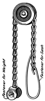
Fig. 72
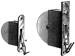
Fig. 73
63. Sash Balances.—By the use of sash balances, one of which is shown in Fig. 73, there is no necessity for weight boxes, counterweights, etc. The contrivance illustrated has been manufactured for many years, and the original intention was to have it displace the sash pulley, cord, and weight for double-hung windows. Installing spring sash pulleys costs more than the older method of hanging by means of counterweights. They are constructed with a long, spiral spring enclosed by a drum, on which the tape a, Fig. 73, winds and thus raises the sash. The coil spring in this balance is made of either light or heavy material, according to the weight of the sash it is intended to counterbalance. They are seldom used, however, except where there is insufficient room for sash weights. The steel tape is liable to be twisted and broken by jarring in operating the sash, and for general use it has been found that the most positive action is secured by pulleys and weights.
64. Weight of Sash and Glass.—In estimating the weight of window sash, in order that the size of the counterweights or of the spring counterbalance may be determined, the weight of the glass per square foot may be taken as follows: Plate glass, 3½ pounds; double-thick glass, 1½ pounds; and single-thick glass, 1 pound. To find the weight of the wooden sash, add together the height and the width of the sash, in feet, and multiply by 2.1 for 2¼-inch sash, by 1.67 for 1¾-inch sash, and by 1.33 for 1⅜-inch sash. The several sizes of sash given indicate the thickness of the sash frame. While these data for determining the weight of sash are not exact, they are sufficiently accurate to fix the size of the sash cords and pulleys and to estimate the weight required to counterbalance them. The best practice in counterbalance sashes, however, is to weigh the sash after it has been glazed; in this manner the exact weight and size of the counterweights required can be determined. The approximate weights of ordinary glazed sash are usually given in the catalogs of manufacturers of sash weights, pulleys, etc., and will be found convenient in determining the approximate weight of sash weights without making the calculations just described when estimating.
65. Sash Locks, or Fasts.—There are many different makes of sash locks for double-hung sash in the market. In Fig. 74 are shown several of the older type of sash locks that have been used extensively. The lock shown at (a) is known as the Champion; that at (b), as the Ives, and that at (c), as the Boston. This type of sash lock, the construction of which is apparent from the illustration, has given satisfaction for a number of years.
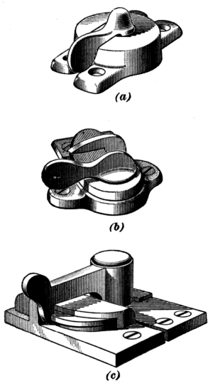
Fig. 74
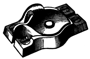
Fig. 75
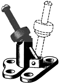
Fig. 76
A newer type of sash lock is that illustrated in Figs. 75 and 76. In Fig. 75 is shown a sash lock known as the Fitch. This lock is made by several manufacturers, and can be procured in all finishes of iron for the cheaper class of buildings, and also in bronze metal for high-class work. It is composed of a helical cam, which is fastened to the top of the meeting rail of the lower sash and engages with a hook, or lug, that is secured to the bottom of the upper sash. The operation of this fastener is rapid, and the rotary movement draws the two sashes together horizontally and forces them in opposite directions vertically. In this way, it holds the sash fast and prevents rattling and air leaks. It also has an advantage in that it cannot be moved by inserting a knife blade between the sashes from the outside. The Yale screw sash fast illustrated in Fig. 76 is an excellent piece of hardware. It accomplishes the same results as the Fitch lock; namely, drawing the sash together by the tightening of a thumb nut on a fine-pitched screw. This nut operates against a semicircular-shaped upright hook, or lug, on the lower sash, thus developing great pressure in the desired direction. While this sash fastener takes somewhat longer to operate than the Fitch, it repays by providing greater security.
66. Sash Lifts.—While sash lifts are not required for the cheapest work, as the window can be raised by pushing against the parting rail or against the mullions, nevertheless they are made to sell at such reasonable prices that it would seem advisable to place them on the lower sash of all buildings, no matter how unimportant.
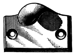
Fig. 77
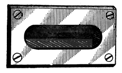
Fig. 78
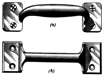
Fig. 79
The common type of sash lift illustrated in Fig. 77 is known as the hook sash lift. This lift is extensively used, and can be procured in any grade or weight, in either cast-iron, steel, or bronze metal, and in any finish desired.
The flush sash lift, the general type of which is shown in Fig. 78, makes a better appearance than the hook lift, and is considerably stronger, from the fact that the casing forming the grip is let into the lower rail of the sash, and the strain is taken by this, rather than by the screws. These lifts are made in either steel or bronze, and in all finishes; they can also be had ornamented to correspond with the lock trim.
For heavy sashes, such as those in public and commercial buildings, the bar sash lift illustrated in Fig. 79 is the best. This type of lift should always be used for heavy sash. A sash lift similar to the type shown at (a) is sometimes fastened to the under side of the meeting rail of the upper sash for the purpose of lowering the sash.
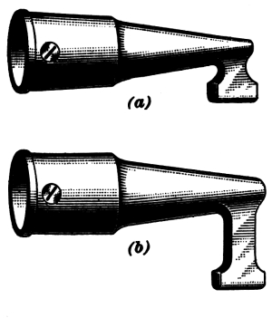
Fig. 80
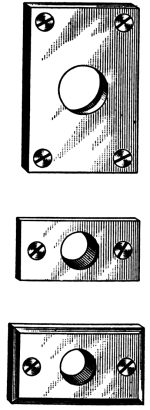
Fig. 81
67. Sash Sockets and Pole Hooks.—In buildings having high ceilings, where the top sash is some distance from the floor, as is likely to occur in institutions, schools, and factories, it is necessary to provide “pull-down” poles for the purpose of raising and lowering the upper sash. The hooks used on the ends of such poles, which are made of some tough wood, are as illustrated in Fig. 80. Unless the upper sash is furnished with metal plates that have a hole, or aperture, the pole will be used against the mullion or upper rail of the window sash and thus mar the woodwork. The plates, or metal sockets, to engage the sash and pull-down poles, are illustrated in Fig. 81. They may be had in all metals and finishes and in several sizes.

Fig. 82
68. Stop-Screws.—The stop-bead screws, or washers, or, as they are more commonly known, the window-stop, or bead, adjusters, types of which are illustrated in Figs. 82 and 83, are necessary hardware adjuncts to the window trim for buildings of the better class. In ordinary work, these stops are secured to the frame by nailing, but when they are fastened in this manner, the stop-beads are disfigured if it is necessary to remove them. A cheap and good way of fastening these stop-beads is to use ordinary round-headed screws. While these adjusters answer the purpose very well, they do not allow for the adjustment of the stop-bead sidewise, so as to take up any shrinkage that might occur in the sash and prevent it from rattling, as well as making it air-tight.
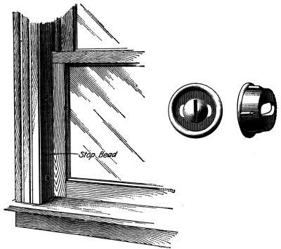
Fig. 83
To overcome this deficiency, a surface washer, as illustrated in Fig. 82, was originated. The surface washer was ordinarily made about ⅝ inch in diameter, and was provided with one large hole about ⅜ inch in diameter or with two smaller holes placed side by side horizontally across the stop. By this means, the proper adjusting of the stop-bead was provided for, the washer covering the opening, or hole, through the stop. However, the defect in this method consisted in the marring of the finished stop when adjustment was required, for the washer left its imprint on the woodwork, and, when shifted, this would show.
The best form of stop-bead washer is illustrated in Fig. 83, and is known as the Taplin adjusting screw and countersunk cup washer. This device is composed of a sunken, or cup, washer with a slotted or horizontal hole in its base frame, so as to allow about a ³/₁₆-inch adjustment. This adjustment, as can be clearly seen from the figure, is made without marring, or disfiguring, the stop-bead in any way. These countersunk washers may be had in bronze or steel, those made of steel being finished to match the hardware, as desired.
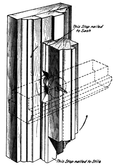
Fig. 84
TRIMMINGS FOR PIVOTED AND CASEMENT SASH
69. Sash Centers.—When a transom sash is hung at the top or the bottom, regular hinge butts may be used; but where a sash is pivoted at the center, either on the sides or at the top and bottom, a pivoted arrangement, termed a sash center, is needed. For large sash or heavy transoms, and especially for those that are exterior sash, the rabbeted center should be used. This type of center is illustrated in Fig. 84; its construction gives great strength and completely closes the joint against light and water.
An excellent type of center, known as the Howarth sash center, is illustrated in Fig. 85, the method by which it is attached to the frame and sash being clearly indicated. By this arrangement, the two parts of the center fold, or butt, against each other and form a tight joint, the stop-bead for the sash at the top and bottom being arranged as indicated at a a.
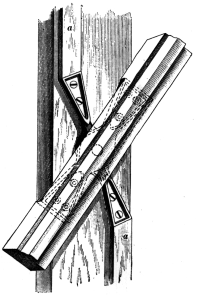
Fig. 85
There is a sash center, known as the Tabor, that is constructed as shown in Fig. 86. This center is used for very large sash that are vertically pivoted; that is, arranged with a center at the top and bottom. Such sash as these are used extensively in office buildings, because, by their use, the entire window may be thrown open at one time. The Tabor device consists of a special sub-sill, which engages with a ribbed joint strip placed on the bottom of the sash. By this means, a weather-tight joint is secured, and the sash is firmly locked in a closed position. By throwing a lever, the sash is raised above the astragal, or sub-sill, and can then be operated. The top rail is supplied with a filling strip having an irregular joint at the intersection with the sash, and is held firmly by a coil spring encircling the top pivot.
In Fig. 87 are shown several sash centers of the common type. These possess no particular merit, but are much used for common work.
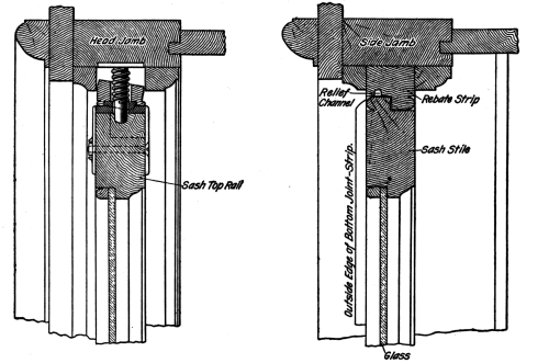
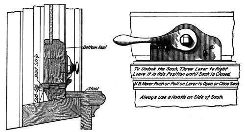
Fig. 86
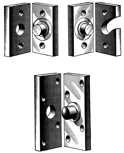
Fig. 87
70. Transom Lifts.—The transom lift illustrated in Fig. 88 is distinctly an American device for operating and fastening the transom lights over doors. This device is used extensively in hotel and office buildings. It is made in various styles and sizes necessary to meet the several requirements. The transom lift consists of a vertical sliding rod that is placed on the door jambs, as at a, with an arm at the top connecting it with the sash, as at b. Near the bottom is a clamp, or grip, that holds the bar a in any desired position. By a vertical movement of the rod, the sash is caused to swing. Transom lifts may be had for transom sashes that are pivoted at the center or for those which are hinged at the top or the bottom. At (a) and (b) in Fig. 88 are shown the types of transom lifts for center-pivoted sash; the former arranged so that the sash pitches outwards, while in the latter the sash pitches inwards. At (c), the device is shown where the sash is hinged at the top, while at (d) the sash is hinged at the bottom. The several kinds of transom lifts made by the various manufacturers are practically alike, except for variations in the form of the grip, or clamp. The range of sizes and quality of transom lifts is large. The commercial article may be obtained in steel, copper or bronze plated, or in bronze or brass. They are made in ¼-, ⁵/₁₆-, ⅜-, and ½-inch sizes, the size being determined by the weight of the sash and the degree of rigidity and solidity desired to be obtained and expressed. For good work, the ⅜" and ½" diameters are used. The rods may be obtained in lengths of from 3 to 12 feet. In specifying or ordering transom lifts, the rod should always be sufficiently long to reach within 5 feet of the floor.
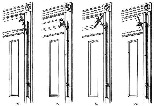
Fig. 88
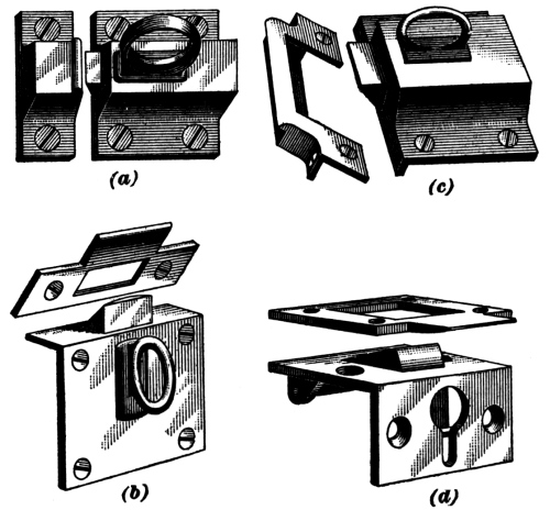
Fig. 89
71. Transom Catches.—In Fig. 89 are illustrated types of transom spring catches, or bolts. These devices are provided in the several forms shown to meet various conditions. Those shown at (a), (b), and (c) have a ring, or eye, in the handle, to which an operating cord may be suspended, or into which a pull-down hook may be inserted, to operate the sash. The transom catch at (d) is made expressly for operation by means of a pull-down hook. In very wide windows, for the purpose of limiting the opening of the sash, these catches should be used in conjunction with chains instead of with transom lifts.
72. Transom Chains.—In Fig. 90 are illustrated several types of transom chains. The chains shown at (a) and (b) are suitable for sashes weighing not more than 25 pounds, while that at (c) is sufficiently strong for sashes weighing over 25 pounds. These chains are fastened to cleats furnished with countersunk screw holes for securing readily to the frame and sash. When the sash is hinged at the bottom, these chains are used to limit the opening of the sash. They are sometimes employed as an additional guard, to prevent the sash from falling in case the sash lifter becomes broken. The ordinary lengths of sash chains range from 8 to 24 inches, the latter length being sufficient for the opening of the largest sash.
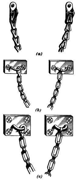
Fig. 90
73. Casement Trim.—The term casement applies properly to any hinged sash. It is, however, usually limited to windows that have a sill set some distance above the floor. Where the casement sash extends to the floor, the term French window is generally applied, although frequently the terms are confused. In designing casement windows, the details of the hardware should be such that the casements can be made weather-tight; and in laying out the full-sized details for the mill work for a casement sash and frame, the available hardware should be studied, so that the woodwork may be arranged to conform to it.
74. Casement Bolts and Fasts.—Casement sash may be provided with any good form of top and bottom bolts or hinged sash fasteners, but these should be supplemented by a good latch or cupboard catch at the center. Special turnbuckles, or casement fasts, constructed as shown in Fig. 91, are on the market. All of the catches shown will securely fasten the sash, but the types shown at (a) and (d), Fig. 91, will draw the sash tightly against the frame when the buckle, or fast, is drawn in place. In countries where casement sash are in general use, the necessary fastenings, including the top and bottom bolts, are embodied in one structure, as described in the following article.
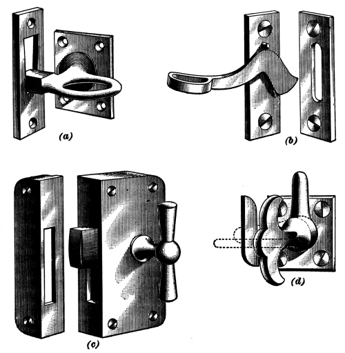
Fig. 91
75. Cremorne Bolts.—In the best work, the Cremorne bolt is used for casement windows. This device consists of a vertical rod divided at or about the middle of its length, thus making two pieces, and is operated by a knob, or handle, at that point. Types of ornamental Cremorne bolts are illustrated in Fig. 92. As shown, the upper and lower ends of the rods, or bolts, slide vertically and in opposite directions, being operated by the turning of the knob, or handle. These bolts are furnished with suitable strikes, either of the plate or the box form, which are attached to the window at the top or the bottom. Since the ends of the bolts are beveled, they press the two sashes tightly together and against the sash frame when they are thrown in. A single movement of the knob, or lever handle, is sufficient to release both bolts.
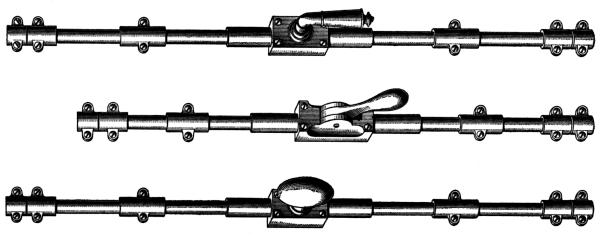
Fig. 92
76. Espagnolette Bolts.—In Fig. 93 is shown the Espagnolette bolt, which is similar in construction to the Cremorne bolt. This bolt consists of a vertical rod, but instead of being in two pieces, as in the Cremorne bolt, it is in one piece. This rod has hooks at each end, and, by a rotary motion, engages pins, or plates, in the window frame and thus draws the sashes together and against the frame. These bolts are usually operated by a pendant handle, which, when lifted to a horizontal position, will release the rod so that it may be rotated to fasten or to release the sash. For very high sash, a supplemental design may be used by providing a tapered hook on the opposite sash for the pendant. The Espagnolette bolt is usually heavier than the Cremorne and exerts more power in forcing the sashes against the frame; it is also more expensive. Both bolts, however, are available for use on doors as well as on windows, and lend themselves admirably to decorative treatment, as shown in the illustrations.
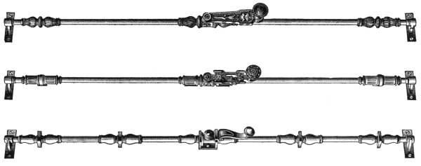
Fig. 93
The same care should be exercised in the selection of these bolts as for other hardware, and when ordering them, full-sized details should accompany the order, showing sections through the top rail and head-jamb, the bottom rail, the sill, and the lock stile. The exact measurement of the height and the width of the openings should also be given, and the information should state whether the sash swings inwards or outwards. The hand of the active leaf, as well as the height of the handle from the floor, should also be given. In Fig. 94 are shown sections through a casement sash, illustrating the conditions requiring the use of Espagnolette bolts, and, as just stated, sections similar to these should be furnished the dealer, or manufacturer, so that these bolts will fit the construction when they are delivered.
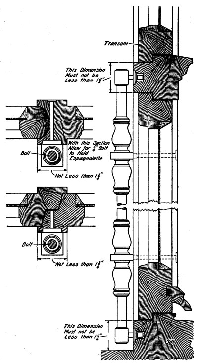
Fig. 94
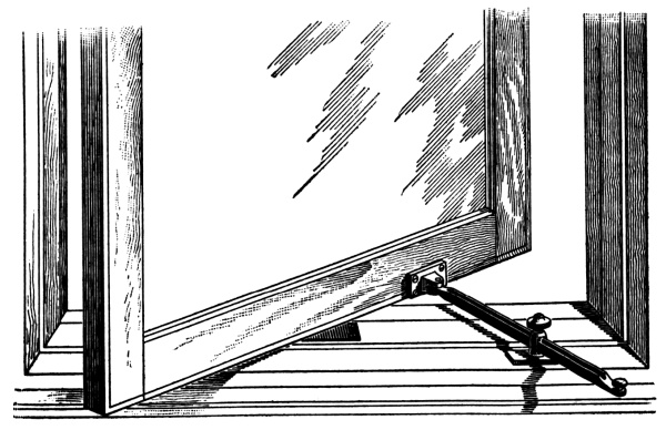
Fig. 95
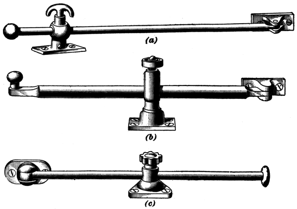
Fig. 96
77. Casement Adjusters.—In order to hold pivoted or hinged sash in a partly open position, it is necessary to use casement-sash adjusters. These adjusters, and the method of applying them, are illustrated in Fig. 95. In this figure is shown the adjuster applied to a sash pivoted at the top and the bottom, but the device can as well be applied to a casement sash hinged at the sides.
There are many forms of casement-sash adjusters, the common types being illustrated in Fig. 96. They are arranged for sash that open either inwards or outwards, and may be applied to either pivoted or hinged sash. Most casement-sash adjusters usually consist of a rod or a bar attached to the sash by a hinged or pivoted joint. The rod passes through a clamp on the frame, or sill, and this rod, when the clamp is tightened, holds the sash firmly in any desired position.
78. Window and Shutter Operating Devices.—The sash-operating device is provided for the purpose of controlling a number of sash in a line by one piece of mechanism. Frequently, divided sashes are arranged side by side in skylights, clearstories, and monitors. These windows are usually some distance from the floor, and the operating device must be so arranged that it can be worked conveniently. The device illustrated in Fig. 97 is known as the Lovell window and shutter operating device, and consists of two longitudinal sections of pipe shafting a connected to cog racks b at the end. These cog racks in turn engage with a cog, or wheel, shaft c, as indicated in the figure. Connecting arms d, with swivel joints at each end, are arranged between the pipe shafts and the sash. The ends connected to the sash are secured to the same by means of plates and wood screws, and the swivel joint at the other end is provided with a sleeve, or socket, that is secured to the pipe shafts with a setscrew. The commendable feature of this device is that it is operated by a straight push or pull of the arm, instead of a twist, as in some other devices on the market. When the chain, or rope, around the large chain wheel is pulled, the cog is turned, and as it engages the racks, it thrusts one pipe horizontally in one direction and the other in an opposite direction. By this means, the connecting arms to the sash approach one another and lengthen the distance between the shafting and the sash, which movement tends to push the sash open, the sash being closed by the opposite operation. By this device as much as 500 feet of sash may be operated by one wheel, or “power,” as it is called. This chain wheel, or power, may be located either in the center or at the terminals, and by careful adjustment will simultaneously close all the sashes tight against the frame.
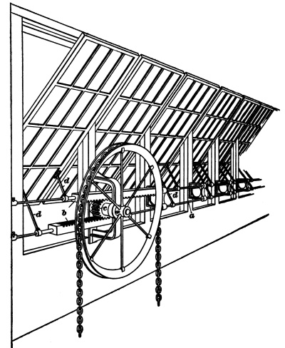
Fig. 97
DOOR HARDWARE AND ITS APPLICATION
79. Door Pulls.—In Fig. 98 are illustrated two well-known types of door pulls. The pull shown at (a) consists of a handle that is usually mounted on a plate and attached to either storm or single-acting doors, although, occasionally, this type is used on double-acting doors with the word “push” or “pull” inscribed on the plate. When used on double-acting doors, the door pull has a tendency to obviate the habit of persons placing their hands on the moldings near the glass when operating the door, but is subject to the objection of inviting a pull to open the door even with the word “push” inscribed on the plate.
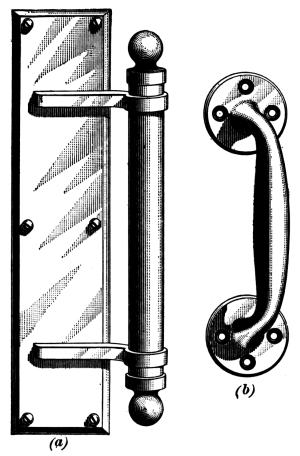
Fig. 98
Door pulls are made in various metals, both in plain and ornamental design, some of the latter being very elaborate, as will be observed from Fig. 99.
80. Kick Plates.—A kick plate is a modern device that may be applied to the bottom of doors to protect the woodwork from injury and wear, being used chiefly for double-acting doors and doors of public buildings. These plates are frequently made of sheet metal, but are much handsomer when made of cast metal and ornamented to harmonize with other metal work of the door.
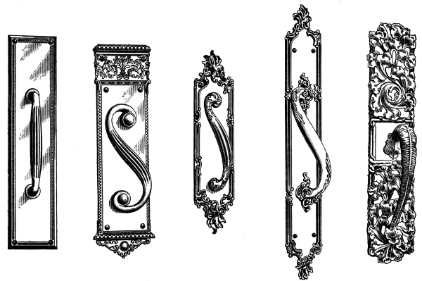
Fig. 99
Kick plates should completely cover the bottom rail of the door, but if cost is the controlling factor, they may be cut down in height so that a margin of wood the same width as the side, or lock, stile shows above the plate. For instance, if the bottom rail is 12 inches in height and the stile is 5 inches wide, the kick plate should be 7 inches high. In all cases, kick plates should extend the full width of the door, allowing enough margin, when used on double-acting-doors, for the rounding of the edges. When used on single-acting doors having rabbeted jambs, the rabbet of both jambs should be deducted from the length of the kick plate. A typical kick plate of plain pattern is shown in Fig. 100. Such plates are generally sold at a square-inch price.
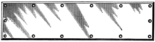
Fig. 100
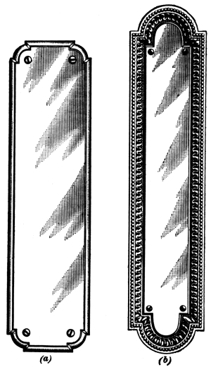
Fig. 101
81. Push Plates.—On double-acting or single-acting doors, such as storm and duplex doors, push plates are used to protect the woodwork against soiling and wear from handling. These plates are made in various sizes, and are either plain or ornamented to harmonize with the other hardware. To obtain good results, push plates should be as wide as the lock stile, where possible, and from 12 to 30 inches long, according to conditions and use. Plates 20 inches or less in length should be placed on the door so that the distance from the floor to the center of the plate is about 4 feet 6 inches; for larger plates the distance from the floor to the top of the plate should be 5 feet. If used in connection with a cylinder dead lock, the plate should be cut or drilled, preferably near the bottom, to allow the cylinder of the lock to pass through the plate. The plain type of push plate is illustrated in Fig. 101 (a), while one of more ornamental design is shown at (b).
82. Sign Plates.—Although metallic plates with lettering are not usually included in the hardware specifications, they find extensive use in hotels, banks, and other public buildings. The inscriptions available cover every possible demand, including titles of officers, names of rooms, etc. Sign plates of various sizes can be procured in the following finishes: Bronze, brass, or nickel with either sunken or raised black letters; bronze or brass with black background or matte; white porcelain plate with blue, red, or gilt letters; and blue porcelain with white letters. Two typical sign plates are shown in Fig. 102.
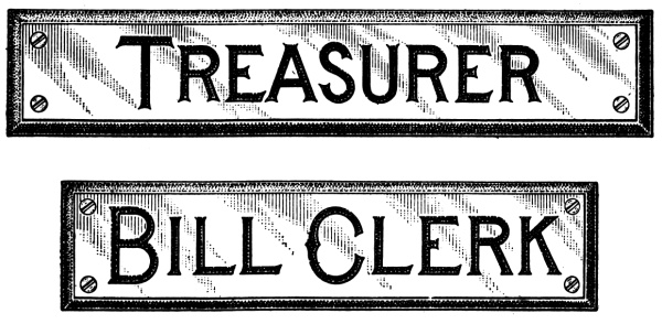
Fig. 102
83. Door Stops and Holders.—Since door checks and double-acting doors have come into more extensive use, the necessity of holding doors open has created a demand for door stops and holders. The door stop is a device for limiting the backward swing of a door. This device may also be constructed so as to perform the additional function of holding the door in an open position; it is then known as a door holder.
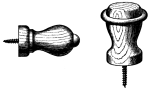
Fig. 103
The ordinary door stop is simply a wooden knob with rubber tip, or ring, that may be fastened to the floor or a baseboard, and is usually made up in the forms shown in Fig. 103. Better grades made of iron or bronze are also available. These come in various shapes, as shown in Fig. 104. Frequently, as shown at a, a hook for fastening the door in an open position is combined with the door stop.
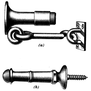
Fig. 104
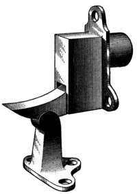
Fig. 105
The door stop with the hook holdback is not always convenient to use, so that the automatic holdback, or door holder shown in Fig. 105 is sometimes employed. This holder can be disengaged by a pull on the handle of the door and automatically catches the door in an entire open position.
Where it is desired to hold a door in any position or to release it quickly, the rubber-tipped holder shown in Fig. 106 should be used; this device is easily operated and controlled by the foot.
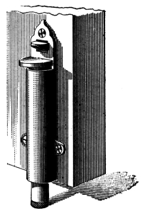
Fig. 106
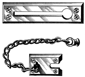
Fig. 107
84. Chain Door Fastener.—The type of chain fastener illustrated in Fig. 107 is generally used on exterior residence doors. This device allows the occupants to open the door partly without permitting entrance. It consists of a heavy chain, one end of which is attached to a plate, which in turn is fastened to the jamb with screws. The other end of the chain carries a ball or a hook that may be inserted in the slot of the long plate, which is attached to the door. By this means, the door may be opened only slightly, until the ball of the chain is released from the slot.
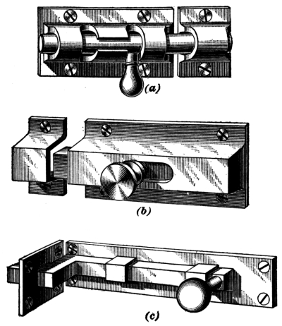
Fig. 108
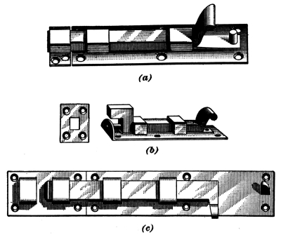
Fig. 109
85. Door Bolts.—A large variety of door bolts is now on the market. These bolts are made in all sizes, in wrought steel, cast iron, brass, and bronze, and may be procured in any finish desired. The several types of bolts used in common practice are illustrated in Figs. 108 and 109. In Fig. 108 (a) is shown a type of barrel bolt; at (b) is shown what is known as a cased bolt; and at (c) is shown a necked bolt. Fig. 109 (a) shows a spring bolt, (b) a spring-necked bolt, and (c) a type of shutter bolt. Various types of mortise bolts are illustrated in Fig. 110.
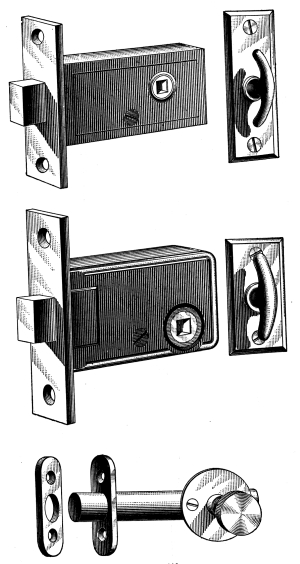
Fig. 110
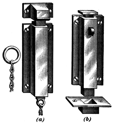
Fig. 111
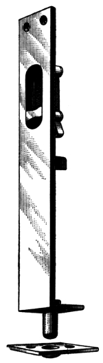
Fig. 112
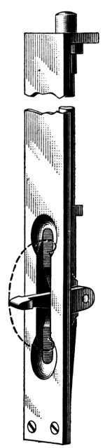
Fig. 113
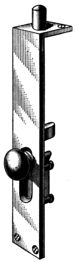
Fig. 114
86. Chain Bolts and Foot-Bolts.—A type of rim bolt used chiefly to secure the standing leaf of double doors is shown in Fig. 111. These bolts are made in various sizes, finishes, and grades, and in both plain and ornamental design. In the figure, the chain bolt is shown at (a), while the foot-bolt is illustrated at (b).
87. Flush Bolts.—Bolts that are intended to perform the same function as chain bolts and foot-bolts, but are sunk into the stile of the door flush with its surface or edge, are known as flush bolts. These bolts, which are illustrated in Figs. 112 and 113, are made in various styles, grades, and finishes, from the smaller kinds for cabinet purposes to the large, double-mortise extension bolt. A flush bolt with a knob is shown in Fig. 114, while a heavy, T-handle extension bolt is shown in Fig. 115.
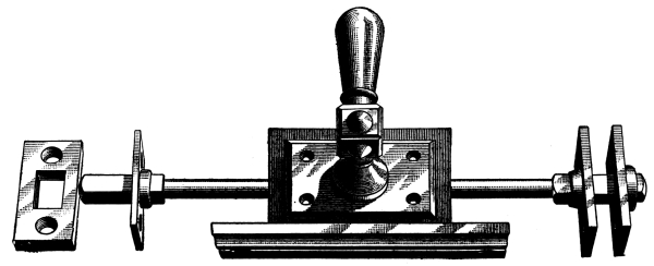
Fig. 115
88. Door Springs and Checks.—During recent years considerable improvement has been noticeable in the construction of the devices known as door springs and checks. Formerly, the common torsion rod and coil springs, which are illustrated in Fig. 116, at (a) and (b), respectively, were the only articles of this kind available. These devices have been in extensive use for many years, and have performed the work of closing the door, but not without the unnecessary bang and slam made by the door when striking the jambs. This was overcome to some extent, however, by the introduction of the air-check, which depends on the use of an air cushion to resist the force of the spring. In effect, each check is a small air pump.
Prominent among the older type of air-checks is the Eclipse made by Sargent & Co. This check is clearly illustrated in Fig. 117. At (a) and (b) are shown two methods of applying the Eclipse air-checks. In (a), the spring-check that closes the door is shown at a attached to the door, while its lever-arm is fastened to the door casing. The cylinder b is also secured to the door, and the piston c, operating in the cylinder, is applied to the door casing. At (b), the parts are differently arranged. The spring-check occupies the same relative position as shown in (a), its lever-arm being shown at a, while the piston c is fastened to the door and the cylinder b affixed to the head-jamb of the door frame. Either method is adapted for inside doors, but that shown at (b) is preferable for doors opening outwards, on account of fewer parts being exposed; the spring-check and its lever-arms, in this case, being the only parts exposed to the weather. In construction these checks consist of a cylinder b with a polished interior, in which works the piston c. On the end of the piston there is provided a cup made of leather that has previously been soaked in oil. By the insertion of the piston into the cylinder as the door closes, there is a tendency to compress the air in the cylinder, thus forming an air cushion with air outlet at the caps. These outlets can be regulated by turning, or screwing, the cap to the right or the left, as the case may require.
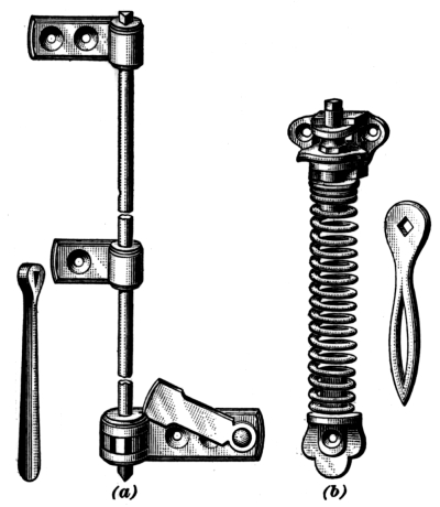
Fig. 116
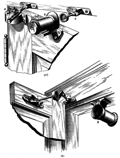
Fig. 117
Devices of this kind, however, did not prove satisfactory until the introduction of the Yale-Blount, or hydraulic, combined spring and check, which is shown in Fig. 118. In this device, the coil spring a, shown in (b), is enclosed in the vertical portion of the check, the regulating of the tension being accomplished by turning the ratchet sleeve b with a wrench made for that purpose. The check enclosed in the horizontal part consists of a metallic piston c, without packing, that moves in a tightly sealed metallic cylinder containing a lubricating and non-freezing liquid. The movement of the door in closing depends on the escape of the liquid through a by-pass from one end of the cylinder to the center, this by-pass being controlled by a small valve that may be readily adjusted to produce any desired action of the door and thus permit the door to be closed silently, with a smooth, steady motion, and without rebound. Since the introduction of the Yale-Blount type of check and spring combined, other manufacturers are making similar styles, the most prominent being the Bardsley, the Corbin, the Sargent, and the Ogden.
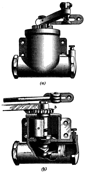
Fig. 118
89. Sliding-Door Hangers and Track.—The first sliding-doors were usually carried on sheaves, or rollers, located at the bottom of a door, these rollers traveling on a metal track, which was either inserted in the floor or placed on its surface. This system, however, has been displaced by the more modern sliding-door hanger, which suspends the door from the top. The carriers containing the rollers, or wheels, run on an overhead track placed in a recess formed for that purpose above the soffit of the doorway.
The use of the overhead hanger requires a special construction of the head-jamb, not only to provide space for the overhead track, but also to furnish proper support for the brackets securing the same. It is therefore a good plan to determine in advance the type of hanger to be used, in order that the framing and other details of the doorway may be made to conform to it. The most important features to be considered in the selection of sliding-door hangers are the strength and stiffness of track, the provision for adjusting and reducing friction and noise, the strength and quality of the several parts, and the facility with which these parts can be fitted in place and adjusted when in use.
In order to overcome noise, the original overhead hanger was made with wooden track, which was placed on each side of the recess. On this track rolled the wheels in pairs, being generally riveted to an axle and having a space between them. The frame of the hanger traveled on the axle from end to end, to overcome friction, the adjustment being only in the hanger frame. Of this type of door hanger, the Prindle, the Stearns, the Warner, the Ives, and the Richards were the most widely used. The Ives improved wooden-track, house-door hanger is illustrated in Fig. 119.
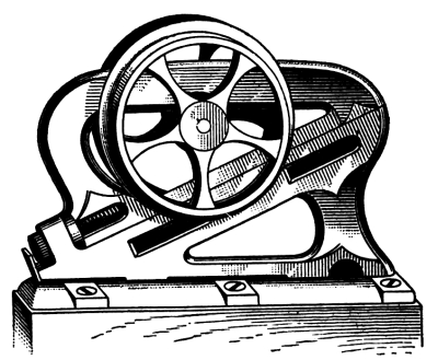
Fig. 119
Another form of sliding-door hanger, which is considered an improvement over the type just described, consists of the single or side steel-track hanger of the Lane or the Richards make. These sliding-door hangers are constructed entirely of steel, and the hanger proper has frictionless bearings, on the principle of the wooden-track hangers, but with one wheel to each hanger, running on a steel track fastened to one side of the recess. This combination is quite an improvement over the old-style hanger, and can be placed in position more readily. The wheels of these hangers, as shown in Fig. 120, are constructed of two plates of steel, between which is placed a fiber wheel that is held in position by through rivets. The fiber portion of the wheel comes in contact with the track, while the plates act only as flanges, thus tending to reduce the noise caused by the operation of the door.
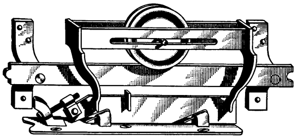
Fig. 120
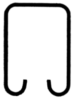
Fig. 121
The hangers most extensively used at present are the trolley type, of which the Coburn is the original and the best of the various kinds. The track, a typical section of which is shown in Fig. 121, is made of sheet steel, which is bent or folded into various forms, depending on the particular make. The carrier is contained in the interior of the track. The several features of this type of track and hanger are illustrated in Figs. 122, 123, and 124, which likewise show the method of attachment and the detail construction of the door head, or soffit, necessary to receive these tracks and hangers.
This type of sliding-door trolley track is also sometimes lined with wood placed in the steel trough, or track, as shown in Fig. 125. This makes the device absolutely noiseless, although the regular types operate with very little noise. Besides the Coburn trolley and track, there are the Richard and the McCabe. Both of these makes possess merit. The trolleys, or carriers, are constructed with both fiber and iron wheels, with ball bearings, running on a wooden or metal track, according to the type.
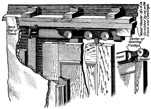
Fig. 122
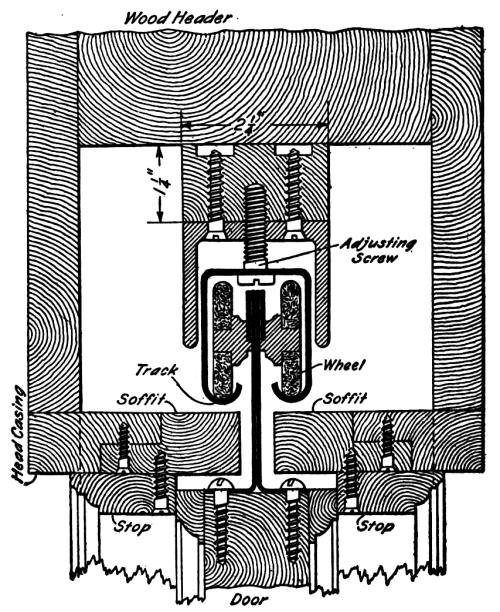
Fig. 123
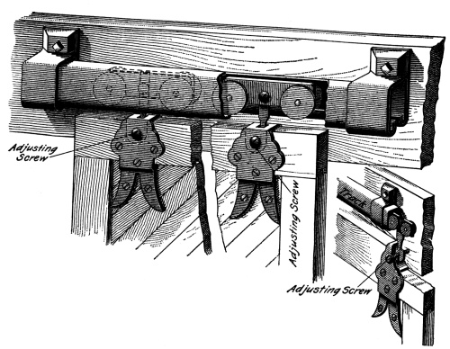
Fig. 124
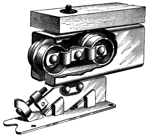
Fig. 125
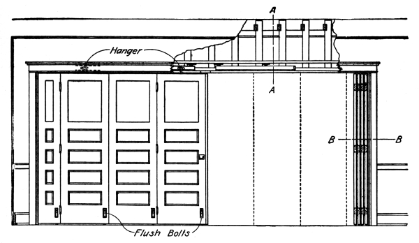
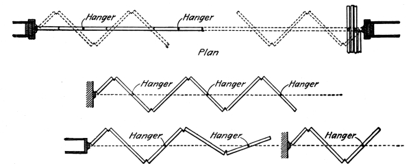
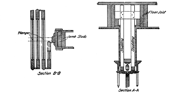
Fig. 126
This type of hanger and track is made in all sizes, from the smallest, for hanging small bookcase doors, up to the very largest, for warehouse doors. As shown in Fig. 126, trolley hangers are made for doors of special design, such as accordion and parallel doors used to close up large openings. They are also made for elevator doors, freight-car doors, barn doors, and automatic fire-doors, with special construction to suit the various purposes.
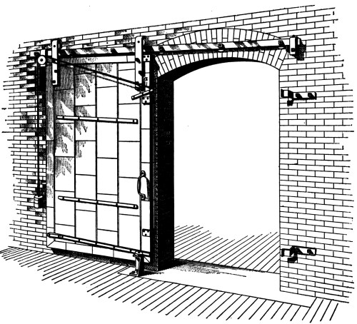
Fig. 127
In factory and similar buildings, it frequently happens that one portion must be separated from another by brick fire-walls and that the openings in these walls have to be closed with tin-covered doors as required by the National Board of Fire Underwriters, the object being to reduce the fire hazard. Wherever possible, these doors are made sliding and arranged so as to close automatically, being hung on a slanting track with an incline of ¾ inch to the foot, and also counterbalanced with weights so that the door will stand at any point, as shown in Fig. 127. The cord or rope attached to the weights passes over a pulley and is attached to the door with a fusible link, as at a, which, in case of fire gives way and allows the door to close automatically.
The doors are usually constructed of seasoned white pine or similar non-resinous wood, using three thicknesses of ⅞-inch matched boards, the outside layers to be vertical and inner layers horizontal and thoroughly fastened together with wrought-iron clinch nails, driven in flush and well clinched. The doors are then covered with 14" × 20" IC bright charcoal tin plates of not less than 107 pounds to a box of 112 sheets. All joints are locked ½ inch, without soldering, and nailed under the seams.
The track for these doors is best made of round-edge bar iron or tire steel, ⅜ in. × 3½ in., being bolted to the wall with through bolts having nut and flanged washer on the opposite side, and held from the wall by cast-iron track brackets. The hangers are of wrought iron, ⅜ in. × 3½ in., provided with roller-bearing wheels and are attached to the door with at least two bolts. The binders are of wrought metal, ⅜ in. × 3½ in., with angle flange at back end to notch in the wall and so arranged as to grip and force the door against the wall when closed. In connection with this, a wedge is placed at the end of the lower chafing strip, and, when the door is closed, engages with the stay roll so that the door will be held close to the wall on the opposite side. Two chafing strips of ¾-inch, half-oval metal are placed on back of door with 1" × ⅛" flat strips of same length in front and bolted through the door. Bumper shoes are also used to prevent the binders from mutilating or damaging the tin covering at the points that strike the binders.
90. Door Knockers.—Although the medieval door knockers have been replaced by the modern door and electric bell, they are still used occasionally for decorative purposes, and, when required, they should be selected and specified with the finishing hardware. Door knockers are made in various styles, sizes, and finishes—in iron, brass, or bronze—to match the several designs expressed in hardware. The elaborateness of the designs of this somewhat ornamental piece of hardware is shown in Fig. 128.
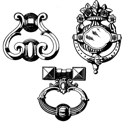
Fig. 128
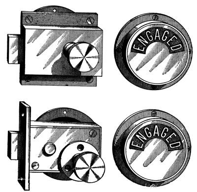
Fig. 129
91. Water-Closet Door Trim.—The construction of water closets in public buildings has brought forth special hardware to meet the various conditions of convenience, simplicity, and hard usage. In ordinary work, the doors of water-closet compartments are secured with a hook or a barrel bolt, while in the better class of work, as in hotels and public places of this character, mortised thumb or knob bolts or, better, indicator bolts are used.
Indicator bolts, as shown in Fig. 129, made both mortise and rim, are available for water-closet doors. In either case, the bolts are mortised into or placed on the inside of the door with the indicator case on the outside. The indicator dial has a spindle on the back, and this engages with the knob that operates the bolt. When the bolt is thrown, the indicator shows the word “Engaged,” and when turned back, the word “Open” appears.
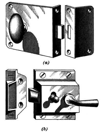
Fig. 130
A simple form of fastening for water-closet doors is shown in Fig. 130, which illustrates the flush, or half-mortise, knob bolt at (a), and the water-closet rim latch at (b). The rim slide bolt is also used for securing water-closet doors. All of these bolts are available for wooden partitions, and may be had for marble or slate work, when special strikes and bolts for fastening will be required.
Jamb door stops are seldom required for water-closet doors hung to wooden partitions, but when needed there is to be had a simple stop with a rubber tip that will answer all purposes. Where stops are required for doors hung to marble partitions the type shown in Fig. 131 may be used. This stop has a clamp device that is attached to the marble slab by bolts and it will be observed forms a combination stop and strike for the latch or bolt.
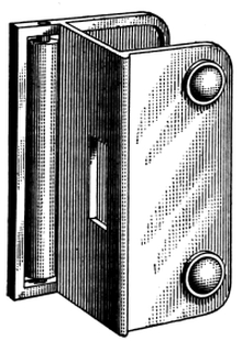
Fig. 131
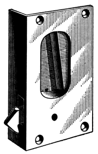
Fig. 132
Other water-closet specialties, which are not illustrated here but which are sometimes specified under hardware, are: Coat-and-hat hooks, cigar holders, cigar and paper holders combined, and toilet-paper holders. Each can be procured to secure to either wood or marble, as required.
92. Screen-Door Latches.—There is a light latch manufactured, either rim or mortise, for use on screen doors. It consists of a knob latch similar to a mortise latch or cupboard turn, but in addition to a hub, as in the former, it is furnished with a spindle and a pair of knobs, or lever handles. Latches for screen doors are also constructed with “stop-work,” so that they cannot be operated from the outside except by the means of a key. This latter latch is generally of the mortise type, having escutcheons on both sides.
93. Elevator Latches.—Locks or latches for use on doors of elevator shafts are usually operated by a key from the outside and by a flush lever handle from the inside. The latch illustrated in Fig. 132 consists of a pivoted arm with a hook at its end to engage with a strike on the jamb. This type of latch is the one generally employed.
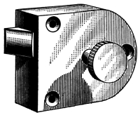
Fig. 133
94. Secret Gate Latch.—In Fig. 133 is shown a secret gate latch, which is used for office gates. Latches of this kind may be had in either the rim or the mortise type. They usually consist of a spring bolt that cannot be operated except by a concealed button or similar device. In the type of latch shown in the figure, the concealed button that controls the latch is located on the lower edge. The knob shown is fixed and does not operate the latch.
95. Ornamental Nails and Studs.—Although the constructive necessity for ornamental studs and nail heads has disappeared under modern methods of wooden construction, they are still used for purposes of decoration, and a great variety may be had. Several stock designs are illustrated in Fig. 134. These nails and studs are made of various metals and in many finishes, having a projecting spur on the back that, when driven into the wood, firmly attaches the ornamental head in place. They contribute effectively to the decoration of important doors, especially extension doors of churches and public buildings.
96. Hand and Bevel of Doors.—Many locks and butts used at the present time are made reversible; that is, they can be used for either right- or left-hand doors. Others are not, and must therefore be specified as right hand or left hand. In this latter class are included loose-joint butts and most locks, the operation of which is different on one side than on the other. All locks with beveled fronts are not reversible, and their use should be avoided where no real need of them exists.
A reversible lock is one having a beveled latch bolt that can be turned over, or reversed, at will, to make its bevel face the opposite direction. This is usually accomplished by removing the cap of the lock and turning over the latch bolt.
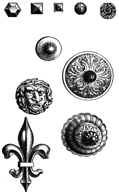
Fig. 134
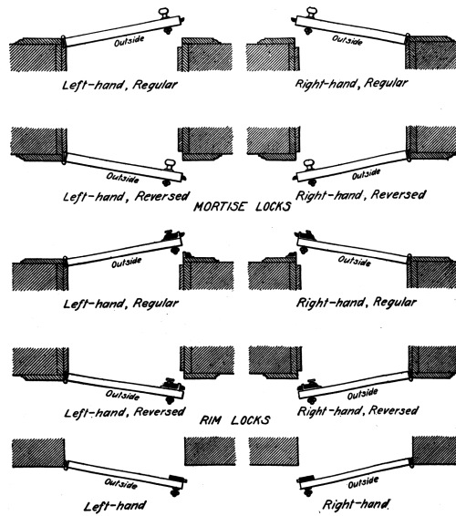
In order that hardware may be ordered intelligently, the hand and bevel of the door should be given where the hardware is not interchangeable, or reversible. Rules to determine the hand of doors have, therefore, been established by the manufacturers of hardware, so that the information may be founded on a uniform basis. Reference to Fig. 135 will materially assist in the interpretation of these rules.
CUPBOARD AND CELL LOCKS
Fig. 135
1. The hand of a door is always determined from the outside.
2. The outside is the street side of an entrance door, the corridor side of a room door, and the room side of a closet door. The outside of a communicating door, from room to room, is the side from which, when the door is closed, the butts are not visible. The outside of a pair of twin doors is the space between them. This rule applies to sliding-doors as well as hinged doors.
3. If, on standing outside of a door, the butts are on the right, it is a right-hand door; if on the left, it is a left-hand door.
4. If, on standing outside, the door opens from you, or inwards, it takes a lock with regular bevel bolt; if it opens outwards, it takes a lock with reverse bevel bolt.
5. A door is beveled when its edge is not at a right angle with its surface, and in this case the front of a mortise lock must be beveled to correspond. This bevel is expressed by stating the thickness of door and the distance that one edge drops back of the other. The standard bevel is ⅛ inch in 2¼ inches, as shown in Fig. 136.
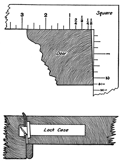
Fig. 136
6. The bevel of a lock is a term used both with mortise and rim locks to indicate the direction in which the bevel of the latch bolt is inclined. If inclined outwards, as for doors opening inwards, it is a regular bevel bolt; if inclined inwards, as for doors opening outwards, it is a reverse bevel bolt (except as to cabinet locks, which, being commonly used on doors opening outwards, are regularly made with reverse bevel bolts, unless otherwise specified).
Mortise locks used with double doors having either rabbeted or astragal joints, must have fronts of corresponding sectional form. To avoid the extra cost of special patterns, the edges, or joints, of such doors should conform to established lock standards. The standard rabbet, or step, in the edge of doors is ½ inch, and the standard astragal joint has a ¾-inch bead.
The proper bevel of a door, if any is needed, is determined by the size of butt and the width of the door, as shown in Fig. 137. The inner corner of the door travels on a radius with the center at the center of the pin of the butt, and must have a clearance to swing free of the jamb casing. This may be obtained by beveling the edge of the door, or, if its edge is left square, by leaving sufficient clearance between the door and its jamb. If the door is of fair width and the butt does not need to be very wide to clear the trim, it will be found that a square edge may be used without resorting to an unduly open joint, thus permitting the use of locks with regular front; that is, not beveled.
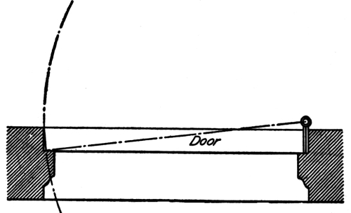
Fig. 137
SHUTTER HARDWARE
97. Shutter Fasteners, or Adjusters.—The most convenient fastener for shutters, or blinds, is the Zimmerman, or Walling, type, as shown in Fig. 138. These fasteners or adjusters secure the shutter in the closed, the open, and several intermediate positions, and are made both japanned and galvanized. They can be used with all styles of hinges, although they are generally combined with regular butts or with the New York blind hinge.
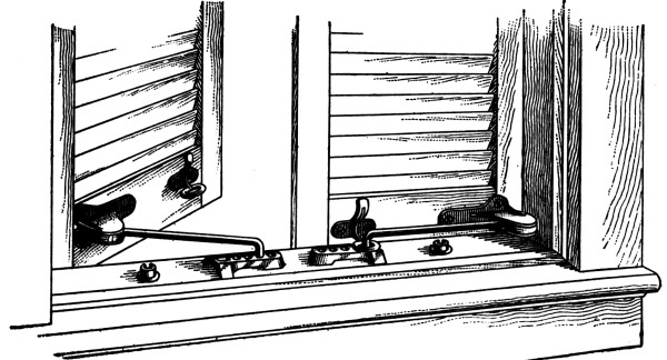
Fig. 138
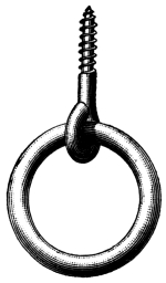
Fig. 139
98. Shutter Rings.—In Fig. 139 is shown a shutter ring. Rings should always be used on solid shutters to close them; the shutter being solid, furnishes in itself no edge which can be clasped in closing, which is not the case with slatted blinds. These shutter rings are tinned or galvanized to prevent rusting, although they may also be obtained japanned. A better type of shutter ring is that having an eye riveted to a plate, which in turn is attached to the shutter with several screws.
99. Shutter Bolts.—Bolts are used for securing both slatted and solid shutters, but are chiefly intended for the solid shutter, which is used for protection. Shutter bolts are made of wrought steel in various sizes, from 6 to 16 inches long, and are to be had either japanned or galvanized. While the same shutter bolts are used on slatted blinds for keeping the blinds in a closed position, they afford little protection, as they can usually be operated through the slats. Common types of shutter bolts are illustrated in Fig. 140. At (a) is shown the ordinary wrought-steel shutter bolt, while the one shown at (b) is practically the same bolt with a lock attachment at a.
100. Shutter Workers.—The shutter worker known as the Mallory is an exceptionally good article for hanging shutters. The lower hinge is made in box form, enclosing the gear necessary to operate the blind; a square shaft connects this with a lever handle, or crank, fastened to the casing inside the building, thus allowing the user to operate the shutter from the inside without opening the sash or screen. The cog gearing in the lower hinge will hold the shutter in the closed, the open, or any desired intermediate position without the use of any other device.
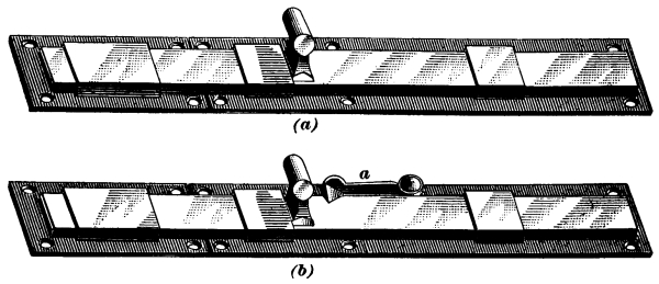
Fig. 140
101. Turnbuckles.—The device shown in Fig. 141 is known as a turnbuckle; it is employed for fastening shutters in an open position against a building. Turnbuckles are made of cast-iron or of wrought steel, and for use on either frame or brick buildings. They may be used in connection with all styles of hinges, and are generally employed on buildings that are exposed to exceedingly strong winds.
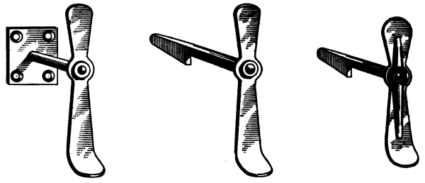
Fig. 141
CABINET TRIM
102. Hinge Butts and Hinges.—For cabinetwork, small, light hinge butts are used. These may be obtained in either bronze or steel, with or without ball tips, and in various sizes. The steel butts of this type are more commonly used, as they can be procured in all finishes, but for high-grade work, bronze metal is always employed. The usual type of cabinet hinge butt is illustrated in Fig. 142.
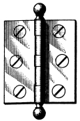
Fig. 142
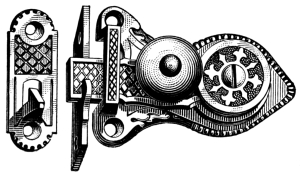
Fig. 143
A surface hinge is sometimes used in place of a butt, in order to eliminate the fitting to the woodwork that is necessary where butts are used.
103. Cupboard Latches.—A convenient fastening for cupboard doors, consisting of a pivoted latch actuated by a projecting knob, is shown in Fig. 143. This type of latch is furnished with two forms of strikes, one for application on the edge and the other for application on the surface of the jamb or door.
This figure shows a stock sample of this type of latch, but the student should carefully note that whenever possible such garish or gaudy ornament should always be avoided in all classes of hardware. Good taste is always better satisfied with simple and direct treatment as shown in Fig. 144; but where ornate styles are adopted, the character of the ornament should be artistically expressed as exemplified in Figs. 128, 134, 153, 155, 157, etc.
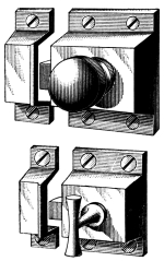
Fig. 144
104. Cupboard Catches.—The cupboard catch differs from the cupboard latch just described, although it is intended for the same purpose. The usual cupboard catch consists of a spring bolt that is operated by a slide knob. It is made in various designs, sizes, and shapes, in both the rim and flush varieties. Figs. 144 and 145 show several types of cupboard catches.
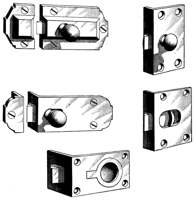
Fig. 145
105. Cupboard Turn.—There is a piece of hardware intended for the same purpose as the cupboard catch, known as the cupboard turn. It is operated by a rotating knob instead of the slide, and is considered the best rim article used for this purpose.
106. Cupboard Buttons.—The cupboard button is an old device, but is little used at the present time, except for the cheapest work. Various types of these buttons are illustrated in Fig. 146. They are made with or without plates, as shown, and may be had in either iron or brass.
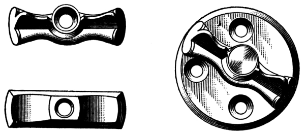
Fig. 146
107. Elbow Catches.—A convenient fastening that is in quite general use for the standing leaf of double doors is illustrated in Fig. 147, from which the operation may readily be understood. This device, which is commonly known as an elbow catch, fastens the doors automatically; it is easily operated in opening the doors, and thus does away with the old-style hook and eye. The strike of the catch should be placed beneath the shelf where possible, using the catch inverted.
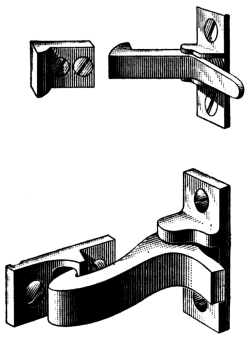
Fig. 147
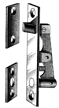
Fig. 148
108. Bookcase Bolt.—The bookcase bolt, shown in Fig. 148, is an automatic fastening device that is mortised into the soffit of cabinets or bookcases having double doors. It is arranged in such a position as to engage with the top of one door, and is operated by the act of closing the other door, which carries the lock, so that both doors are fastened or released by a single action.
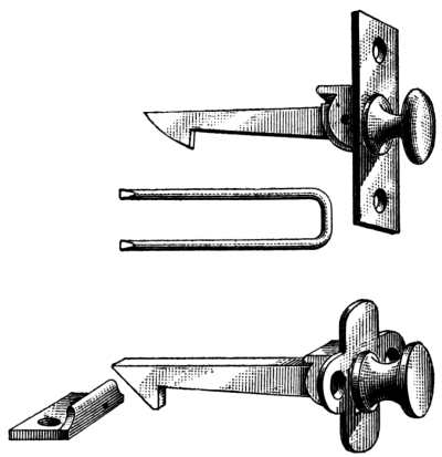
Fig. 149
109. Lever Cupboard Catches.—Another piece of hardware used for securing light doors, or leaves, such as are used in cupboards, bookcases, and wardrobes, is illustrated in Fig. 149. This fastening is very simple and convenient. It consists of a bar that is pivoted to a plate and extends through the door, its inner end being hooked to engage with a strike.
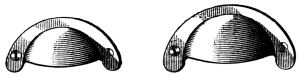
Fig. 150
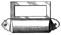
Fig. 151
110. Drawer Pulls.—The drawer pull is a familiar article of cupboard hardware, the usual type being illustrated in Fig. 150. This article can be obtained in iron, steel, brass, or bronze, in various styles and shapes, and in all finishes. Drawer pulls with label plates are extensively used. A type of this drawer pull is shown in Fig. 151.
111. Drop Drawer Pulls.—For cabinetwork, the drop drawer pull, as illustrated in Fig. 152 (a), is used almost entirely. The drop pull is made both plain and ornamented, examples of each style being shown in Figs. 152 (a) and (b) and 153.
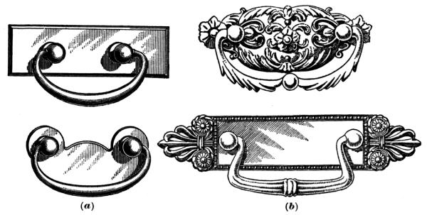
Fig. 152
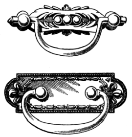
Fig. 153
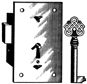
Fig. 154
112. Cabinet Locks.—The type of lock illustrated in Fig. 154 is used on cabinetwork of every description, and can be procured for all classes of construction. These locks are made in rim, flush, and mortise styles, with keys having either plain or ornamental bows.
113. Cabinet Escutcheons.—In order to form a finish and protect the woodwork near the keyhole, the cabinet escutcheon plate is used. These plates are made in various sizes and styles of ornamentation, some designs of which are illustrated in Fig. 155.
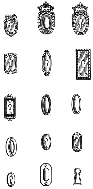
Fig. 155
114. Card Frames, or Label Plates.—An article known as the card frame, or label plate, is used extensively to placard drawers or cupboards to designate their contents. These plates are made in various sizes, and may be procured in bronze and iron and in the usual patterns shown in Fig. 156.
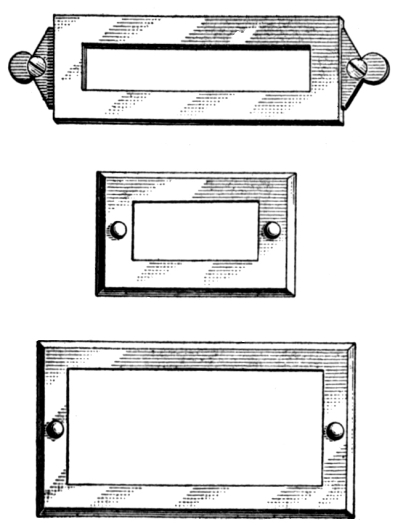
Fig. 156
115. Hinge and Corner Plates.—The hinge and corner plate is an article used solely for decorative purposes on cabinetwork. The variety of designs and sizes now available is such that special patterns are rarely necessary. These plates may be obtained from the hardware dealer in all of the usual metals and in all finishes.
DESIGN AND SPECIFICATION OF HARDWARE FOR BUILDINGS
HARDWARE OF SPECIAL DESIGN
116. Proprietary Hardware.—The manufacturers of hardware have assembled an extensive collection of standard designs in the various styles of ornament, from which fitting selections can be made for almost every use without danger of repetition and without fear that the design selected may become hackneyed by too general use. Therefore, before incurring the great expense entailed by the adoption of special designs, it is advisable that a careful examination of catalog designs be made. Where, however, it is decided to adopt some special design, the facilities of the manufacturer can be effectively utilized to secure the best results at the least cost and with the minimum amount of trouble to the architect or the owner.
Of all of the subordinate elements of interior decoration, there is none that offers a larger opportunity for effective results and for the exercise of personal taste than the metal work of the hardware for doors and windows, whether elaborate and costly, or simple and inexpensive. The knobs, plates, and hinges of a door compel attention by the prominence of their position. If they are inappropriate and unpleasing, they obtrude, while if artistic and in harmony with their surroundings, they attract and provide a finish unobtainable in other ways.
The impress of individuality marks all of the important work of the successful architect, and may be extended properly to the subordinate details of decoration, especially where it is essential that these harmonize with the general scheme. Hence, in some cases, the architect furnishes the designs for the hardware to correspond with the architectural treatment of the building. As, in the case of emblematic hardware, these individual designs involve the additional expense of special drawings, models, and patterns, the plan is seldom resorted to, except where the question of cost is subordinate to that of perfection of result.
117. For many years hardware has been generally regarded as an indifferent detail that could be safely left to the carpenter contractor to select and supply. Even when specified, it has been usually described in a very loose and vague manner, doubtless owing to the technical character of the information required and the difficulty entailed on a busy architect in obtaining and formulating it for use. Where, therefore, the conditions are such that an exact and carefully detailed hardware specification cannot be prepared, the only satisfactory plan is to exclude the finishing hardware from the specifications prepared for the building and reserve it for selection by the architect and the owner.
118. Emblematic Hardware.—Occasionally, it is found desirable to indicate the character or use of a building by introducing one or more appropriate emblems in the design or ornament of the hardware. This is especially true of structures for lodges, clubs, societies, and other organizations, in which case the emblems of regalia, badges, etc. are available for the motif of the design. In municipal, state, or government buildings, the coat of arms or public seal may be introduced in decorating the hardware, and in buildings for railroad companies, banks, etc., the monogram, seal, or name of the corporation is frequently reproduced.
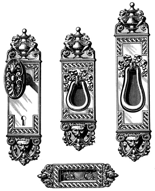
Fig. 157
In all instances, the device selected is usually introduced as the central ornament of the door knob. This ornament is also repeated on escutcheon and push plates, and generally on the larger pieces of metal work; and while it may constitute the sole feature of decoration, it usually has associated with it a border or other ornament.
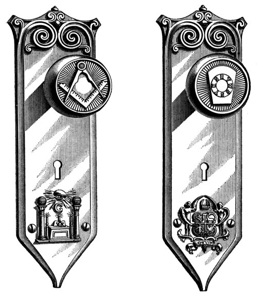
Fig. 158
The use of emblematic hardware involves the use of special designs and patterns, and thus entails a considerably greater cost than the use of standard patterns. In Fig. 157 are shown several standard ornamental designs, while in Fig. 158 are shown pieces of lock trim ornamented with heraldic, or emblematic, designs.
HARDWARE SPECIFICATIONS
119. The methods of specifying builders’ hardware differ considerably. Some architects generalize and use the same form of specification for buildings of all classes, while others are more specific, and itemize all the hardware for the entire operation, giving, besides the description, the catalog number and finish.
The first method is not considered good practice, and, though it involves little work on the part of the architect, it rarely produces the best results. Thus, wherever possible, the specification should be complete and comprehensive, giving a full description of all the hardware in the building.
120. Formerly, builders’ hardware could only be obtained in a few styles, and there was not much choice regarding its physical construction and mechanical operation, so that its selection could be left to the contractor or builder. Specification, therefore, usually included little more than a mere statement that the necessary hardware should be furnished and that it should be of good quality.
In recent years, however, the revolution accomplished in the designing and making of builders’ hardware has elevated it to an important place in decorative art, and, simultaneously, the creating of new and higher mechanical grades has radically changed the requirements in specifications relating to this subject.
121. A few standard forms of hardware specifications that should secure good results will now be considered. For convenience of reference, these several forms are marked I, II, and III. The first two forms are probably as good general forms of hardware specifications as can be written, but, while they answer the purpose in some instances, they should not be used where it is intended to have the general contract include all the hardware, or where it is possible to prepare an itemized specification such as that given in Form III. The numbering of the paragraphs in these forms is continuous with this Section, but in practice they generally start with 1.
FORM I
(See General Conditions)
Note.—Under the head of General Conditions preceding all specifications furnished to contractors by the architect, a series of binding requirements, reservations, and stipulations are specifically stated, and it is most essential that the contractor carefully peruse them, as he is bound by them as well as by the clauses under the heading of Hardware Specifications.
122. Rough Hardware.—Provide all the rough hardware, such as nails, screws, sash weights, pulleys, chain or cord, anchors, screw bolts, and all other material in this line necessary for the completion of the operation.
123. Finishing, or Builders’, Hardware.—All fastenings and metal trimmings used on doors, windows, transoms, closets, cabinets, pantries, etc. will be furnished by the owner and delivered at the building in the quantities and at the times reasonably needed by the contractor, he to apply the same under the direction and to the satisfaction of the architect.
The contractor is to be responsible for all hardware after delivery and until the completion of the building. He shall hang all doors, properly fit all locks, etc., and return them to their original packages until after completion of the painting or finishing, when he shall place them permanently. All knobs shall be covered with Canton flannel, to protect them from injury, and all keys are to be cared for until the building is delivered to the owner. The contractor shall place all keys in their locks or deliver them to the architect with tags attached, indicating where they belong.
The contractor shall furnish the manufacturer or dealer furnishing the hardware with details of woodwork or information that may be necessary in order to understand the requirements and to harmonize the hardware with the cabinetwork, and, where interferences are discovered, to have them adjusted before the hardware is delivered.
FORM II
(See General Conditions)
124. Rough Hardware.—Same as in Form I.
125. Finishing, or Builders’, Hardware.—The contractor shall include in his estimate the sum of _____ dollars ($____) for the purchase of the finishing hardware, which is to be selected by the architect or owner and charged to the contractor. If the hardware costs less than the stipulated amount, the difference shall be deducted from his contract price; if it costs more than herein contemplated, the owner will pay to the contractor the additional amount.
The above hardware is to include all fastenings and metal trimmings used on doors, windows, transoms, closets, cabinets, pantries, etc., and will be delivered at the building in the quantities and at the times reasonably required by the contractor, he to apply the same under the direction and to the satisfaction of the architect.
FORM III
(See General Conditions)
126. Front-Entrance Doors.—Provide for the front-entrance doors, cylinder, mortise, front-door lock and three 5" × 5" loose-pin, ball-tip butts for each door; also flush extension bolts 12 inches and 24 inches long.
127. Vestibule Doors.—Provide for the vestibule doors, cylinder, vestibule latch, keyed similar to the front door, and three 5" × 5" loose-pin, ball-tip butts; also flush bolts, the same as specified for entrance doors.
128. Side-Entrance and Rear Doors.—Provide for the side-entrance and rear doors, locks and butts the same as specified for the front-entrance doors. Exterior basement and kitchen doors to have 5-inch, three-bolt or 4¼-inch, three-tumbler lock and mortise bolt; also three 4½" × 4½" butts for each door.
129. Sliding-Doors.—Provide for all sliding-doors, Coburn trolley hangers; double doors to have locks with astragal fronts, and single doors to have flat-front locks.
130. Double-Acting Doors.—Provide for the doors where indicated double-acting in the plans, Bommer spring hinges or floor pivots of suitable size; also push plates, door holders, dead lock, and kick plates.
131. Miscellaneous Doors.—Provide for all other doors on first floor, 4¼-inch mortise lock with metal knobs and combined escutcheons; also three 4" × 4" loose-pin, ball-tipped butts for each door.
132. Doors on Second Floor.—Provide for all the doors on the second floor, 4¼-inch mortise locks with metal knobs and combined escutcheons; chamber-entrance and bathroom doors to have in addition a mortise bolt. Also provide for these doors, three 4" × 4" loose-pin, ball-tipped butts for each door.
133. Doors in Attic and Basement.—Provide for the doors in attic and basement, 3½-inch mortise locks, pottery knobs, and escutcheons; also two 3½" × 3½" butts for each door.
134. Transoms.—All transoms throughout are to be hinged at the top or the bottom or pivoted (as indicated in the plans), and are to have ⁵/₁₆-inch transom lifts to extend to within 5 feet of the floor.
135. Double-Hung Windows.—The double-hung windows on the first floor are to have approved sash locks and two flush lifts; those on the second floor, in the attic, and in the basement are to have approved sash locks and two flush or hook lifts to each sash. All window stops are to be secured with flush adjusting stop-screws placed not more than 14 inches apart.
136. Casement Windows and Hinged Sash.—Provide for the casement in the lavatory and on the second floor, 3" × 3" tight-joint butts and suitable casement fasteners and adjusters. The basement sash are to be hinged at the top with wrought butts and are to have bolts and hooks and eyes to hold them open.
137. French Windows.—Provide for the French windows in the dining room, 4" × 4" butts, three to each window sash. Also provide for these windows, flush bolts, 12 inches and 24 inches on standing leaf, and mortise turnbuckles.[1]
138. Bookcases and China Closets.—Provide for the doors of the bookcases and china closets, 3" × 3" ball-tip butts, two to each door; also locks and keyplates or mortise latches and knobs, and bolts for double doors. All drawers to have drop drawer pulls, two to each drawer over 20 inches wide.
139. Pantries, Dressers, and Linen Closets.—The doors of the pantries, dressers, and linen closets are to be provided with 3" × 3" butts, together with elbow catches or surface bolts for double doors. Also provide rim cupboard catches or mortise latches with knobs. All drawers over 20 inches wide are to have two drawer pulls. Flour bins are to be hinged at the side or at the bottom, so as to tilt, and are to be supplied with 3" × 3" wrought butts and bar pull or with large T-handled cupboard turn. Place in each closet one (or two) rows of brass-plated wire coat-and-hat hooks (or, bronze-plated cast coat-and-hat hooks) to extend around all sides; these hooks are to be placed not over 12 inches nor closer than 8 inches apart. Furnish rubber-tipped, wooden-base knobs for all doors.
140. Quality and Finish.—All of the above hardware is to be of Blank & Co.’s manufacture, except butts for interior doors, which are to be the Stanley Work product. All the hardware on the first floor, except kitchen and service portion, is to be plain, cast-bronze metal of the design known as ____, and ____ finish. The hardware of the second floor is to be of steel, in plain design and ____ finish. The hardware of the bathroom is to be of plain bronze metal, nickel-plated, while the basement, kitchen, and attic hardware is to be plain steel in ____ finish.
141. Miscellaneous Hardware.—The contractor shall furnish and apply all hardware necessary to complete the building, under the direction and subject to the approval of the architect.
142. The preceding specification is intended to meet the requirements of a residence, but may be changed so as to apply to other buildings by adding to the several items or by omitting some of them. In following the specifications just given, the specification writer should exercise great care in selecting the hardware required, using the best that can be obtained with the money to be expended. In all instances, the name, design, quality, and finish desired should be stipulated.
SELECTION, ESTIMATION, AND APPLICATION OF HARDWARE
143. No other material entering into the construction of a building will pay a larger return in satisfaction, comfort, and permanent economy for the time and care devoted to its selection than the finishing hardware. The range of choice and quality has become too great for the selection to be left to the general contractor under an omnibus specification, and the practice of according to it the benefit of careful and discriminating selection by the architect or client, or both in consultation, is rapidly becoming general. Hardware has become a factor of utmost importance in the interior decorative scheme of the modern building, and its selection demands at least the care accorded to other elements of interior decoration.
The method that should be employed in the selection and purchase of hardware depends primarily on the existing conditions. If the building is intended for the purpose of sale or renting, or if cheapness is the dominating factor, then a competitive method may be expedient; but if the client intends it for personal occupancy or for permanent ownership, then competitive bidding is sometimes not productive of the best results.
In all cases, a preliminary examination should be made of the makes and grades of the commercial hardware available, and the amount that it is desired to expend on this item should be decided on. The process of selection is greatly facilitated by the elimination of articles outside of the grades selected. When the maker’s grade of goods has been decided on, the next step is to select in detail the articles, designs, and finishes to be used in each room, floor, or division of the building, making such notes of the decisions so reached as will be convenient in framing the hardware specification, or schedule.
144. Allowance for Finishing Hardware.—Architects are constantly called on to prepare preliminary estimates on proposed buildings, to assist clients to determine whether they can afford to build. For this purpose, the architect possesses an approximate knowledge of the cost of excavation, masonry, woodwork, etc., so that the necessary expenditure may be computed with a fair degree of accuracy. Builders’ hardware, however, does not readily admit of accurate preliminary estimating, and in many cases the architect merely specifies the sum to be expended for finishing hardware, stating that selections are to be made by himself or his client later, as the work progresses. This system is found in many instances to be satisfactory to all—architect, client, and builder.
The cost of the hardware usually bears a fairly constant ratio to the total cost of various types of buildings. The following figures, which are based on experience, indicate the range in this ratio under ordinary conditions. This schedule gives the ratio of cost of finishing hardware to the total cost of the building, land excluded.
Type of Building Per Cent.
Hotels, large 1.00 to 1.5
Hotels, small 1.50 to 2.0
Apartment houses 1.50 to 2.0
Office buildings 1.00 to 2.0
Office buildings, fireproof .50 to 1.5
Public buildings 1.50 to 2.0
Libraries .75 to 1.5
Hospitals .50 to 1.0
Residences, city 1.50 to 3.0
Residences, country 2.00 to 4.0
145. Taking Off Hardware.—The compilation of the estimate schedule of finishing hardware for a building must be made from the architect’s plans and specifications. Therefore, where possible, this work should be done by a hardware expert or salesman, or by some person who has the ability to read drawings easily and accurately and who is capable of exercising thoroughness in every detail of the work. The first step should be to study the specifications relating to the general work, and especially that portion relating to hardware and carpenter work, to see whether the latter embodies facts that affect the hardware. If such is the case, notes should be made of the fact, and in many cases, by following this rule, miscellaneous information can be gathered that will be invaluable to the contractor and will prevent much doubt as to requirements. The drawings should then be examined, to gain familiarity with the building, the arrangement of the interior, and other details. Having thus acquired a general understanding of the whole subject, the compilation of the quantities may begin.
146. The list of hardware should be compiled in a systematic manner, beginning at a definite point in the building and progressing through the several rooms and floors in a definite order. This will insure the inclusion of every part of the building and the careful consideration of every opening or other place where hardware is required. For example, in the case of a residence, it is customary to commence at the front entrance, including the front and vestibule doors, passing thence to the hall, taking each room on the first floor in due order, passing to the second floor and taking each room on it in like order, and so on until each floor is covered. The attic and basement are usually left until last, because they require a simpler class of goods. The same general system can be followed in the case of hotels, office buildings, apartment houses, etc., the essential point being that an orderly method be followed. The rooms should always be taken in natural sequence, and all openings of similar character totaled and again counted on the drawing, so that the chances of omission are minimized.
147. In the case of doors, it is necessary to make note of the size and thickness, the hand, and the bevel, or rabbet, as required, using in all cases three butts on all exterior doors, and also three butts on all interior doors 7 feet or more high. The size of the butts should in all instances be sufficient to cause the door to clear the trim. The width of stiles and the general construction of the doors should be noted, paying particular attention to the front-entrance doors, as architects sometimes design these regardless of the hardware that is to be used on them. Frequently, a careful scaling and scrutinizing of elaborately designed doors will show a shelf effect returning back to the lock stile, covering nearly half its width, just about where the lock should be placed. Such defects can be remedied easily, if observed in time, by directing the architect’s attention to them.
In the case of sliding-doors, it should be noted whether they are single or double, what is to be the character of the hanger, or rail, and the length of the run, and whether the door has a flat or a half-round astragal. The width of the stile and the size of the friction strip should also be noted, so that the hardware will not conflict with the woodwork, molding, etc., as, where necessary, special backsets can be procured on sliding-door locks to overcome this trouble.
Where double-acting doors are shown, always take note of the thickness, width, and height, also of the width of the lock stile and the height of the bottom rail, so that, if push plates or kick plates are required, the suitable dimensions for them can readily be estimated. The dead locks for these doors should be ordered with oval fronts for single doors and oval fronts and strikes for double doors, to allow for neat fitting to the rounded edge of the doors. Where kick plates are required for double doors of this character, flush bolts should be mortised into the edge of the door, so that the lower bolt will not interfere with the kick plates.
148. In stating the information for windows, full details are needed as to whether they are single- or double-hung, French casement, stationary, or ordinary casement. Double-hung windows 20 inches or less in width require only one sash lift. Extra-wide windows, such as those over 36 inches, should have either bar lifts or two extra-heavy hook sash lifts. The window stops should be studied in detail, so as to estimate the number of screws that will be required for each window. In the case of French windows, it is well to determine the height, the width of the stile, whether the joints are rabbeted, beveled, or flat, the hand, and whether the windows swing in or out; detail cross-sections through head-jambs, casing, and lock stiles should also be procured if possible. In casement sash, the pivoting should be noted, so as to determine whether it is vertical or horizontal; the swing should also be observed, and if the sash are to be hinged, determine whether the hinges should be placed at the top, the bottom, or the sides. As in the consideration of doors, the thicknesses and sizes of all casements should always be noted. Sections through the jambs, trim, and stiles should be taken at the points where the hardware is to be applied.
149. In order to determine the kind and length of the lifters to be used on the transoms, it is necessary to note the distance from the floor to the center of each transom, also whether they are to be pivoted or hinged from the bottom or the top, and how they are to swing. The cross-section through side jambs and casings should always be ascertained, in order to see that the hardware will be suitable to meet the conditions of the trim.
150. It is necessary to learn all details of the pantry, including the thickness and height of doors, whether they are double or single, and the number of each kind. Note all drawers; those under 20 inches in width require only one pull. The details of the flour bins should be examined to determine whether they are to be hinged at the bottom and are to tilt, or whether they are to be curved on plan and are to be hinged at the side, as each condition requires different hardware.
151. Where unavoidable interferences are discovered, or where the plans and specifications are obscure or defective, a note of the facts should be made, and when all such matters have been collected, they should be submitted to the architect for his decision as a basis for final determination.
152. Application of Hardware.—Owing to the fact that hardware has become more intricate in its manufacture and therefore more complicated in its construction, it is found that the proper amount of intelligence is not always exercised in its application. Frequently it is applied so carelessly that the hardware practically loses its most essential features. In the case of mortise-lock sets, all of the better grades are made with easy springs, so that the door will close gently and surely. However, this one feature alone is sometimes obliterated by careless application. The trouble in this direction is principally caused by the carpenter fitting the lock into the door untrue, and then screwing the escutcheons to the doors out of plumb and alinement. This causes the knob shanks, when rotated, to bind, or stick, in the sleeve, or collar, of the escutcheon, thereby holding back the latch bolt after the latch is withdrawn into the lock case. It is also found that proper adjustment is seldom given to the knobs and spindles passing through the escutcheons. In many cases when the hardware is applied carelessly, the owner, not knowing the real cause of the trouble, condemns the best hardware as being cheap and unsatisfactory.
In the application of cylinder locks for either front doors or office doors, it is found that a great amount of inexperience is shown by the average mechanic. In some cases, the locks are inverted, with the cylinder below the knobs, when it is designed to be above; also, sometimes, in reversing a front-door lock with night work, good judgment is not always used.
153. Such troubles as those just described can be easily overcome, and if the methods of applying hardware that follow are strictly adhered to, satisfactory operation will be assured.
Reversing the ordinary mortise, or rim, lock requires no special ability on the part of the workman, as the operation consists of merely taking off the cap and turning over the latch bolt. Where, however, a mortise lock is to be applied, care must be exercised so that it will work properly. First fit the lock into the door at the proper height from the floor, making the mortise large enough for the lock to enter easily. Bore the holes for the knob and the key, and insert the screws in the lock face and drive them home. Now take the escutcheons, or roses, and knobs and apply them to the door, carefully adjusting the knobs and spindles so that there is only slight play in the length. Then true up both escutcheons, by holding one with the thumb and the other with the fingers. When this much is accomplished, turn the knobs right and left to see whether they work properly; if they bind in the collar, adjust the escutcheons a trifle, vertically or horizontally, until the knobs rotate back to the original position in both directions without binding. By using a scratch awl and punch carefully, the exact center of each screw hole may be located, and by holding the awl perfectly true the screws will be started true. The escutcheons may now be released and the screws driven home. If this method is carefully followed, workmen will find that the latch bolt will work properly in almost every case. Always try the knob, when the application is completed, by rotating both to the right and to the left, and if found to bind, always make the proper adjustment before leaving the work.