VOLUME XVII SLICE VIII Matter to Mecklenburg (continued 7)
Reading edition
The colourless character of these ceremonies is plainly due to the fact that they are nothing more than expurgated heathen rites. In Islām proper they have no raison d’être; the legends about Adam and Eve on Arafa, about Abraham’s sacrifice of the ram at Thabii by Mina, imitated in the sacrifices of the pilgrimage, are clumsy afterthoughts, as appears from their variations and only partial acceptance. It is not so easy to get at the nature of the original rites, which Islām was careful to suppress. But we find mention of practices condemned by the orthodox, or forming no part of the Moslem ritual, which may be regarded as traces of an older ceremonial. Such are nocturnal illuminations at Mina (Ibn Baṭūta i. 396), Arafa and Mozdalifa (Ibn Jubair, 179), and ṭawāfs performed by the ignorant at holy spots at Arafa not recognized by law (Snouck-Hurgronje p. 149 sqq.). We know that the rites at Mozdalifa were originally connected with a holy hill bearing the name of the god Quzah (the Edomite Kozē) whose bow is the rainbow, and there is reason to think that the ifāḍas from Arafa and Quzah, which were not made as now after sunset and before sunrise, but when the sun rested on the tops of the mountains, were ceremonies of farewell and salutation to the sun-god.
The statistics of the pilgrimage cannot be given with certainty and vary much from year to year. The quarantine office keeps a record of arrivals by sea at Jidda (66,000 for 1904); but to these must be added those travelling by land from Cairo, Damascus and Irāk, the pilgrims who reach Medina from Yanbu and go on to Mecca, and those from all parts of the peninsula. Burckhardt in 1814 estimated the crowd at Arafa at 70,000, Burton in 1853 at 50,000, ‘Abd el-Razzāk in 1858 at 60,000. This great assemblage is always a dangerous centre of infection, and the days of Mina especially, spent under circumstances originally adapted only for a Bedouin fair, with no provisions for proper cleanliness, and with the air full of the smell of putrefying offal and flesh drying in the sun, produce much sickness.
Literature.—Besides the Arabic geographers and cosmographers, we have Ibn ‘Abd Rabbih’s description of the mosque, early in the 10th century (‘Iḳd Farīd, Cairo ed., iii. 362 sqq.), but above all the admirable record of Ibn Jubair (A.D. 1184), by far the best account extant of Mecca and the pilgrimage. It has been much pillaged by Ibn Baṭūta. The Arabic historians are largely occupied with fabulous matter as to Mecca before Islām; for these legends the reader may refer to C. de Perceval’s Essai. How little confidence can be placed in the pre-Islamic history appears very clearly from the distorted accounts of Abraha’s excursion against the Hejāz, which fell but a few years before the birth of the Prophet, and is the first event in Meccan history which has confirmation from other sources. See Nöldeke’s version of Ţabarī, p. 204 sqq. For the period of the Prophet, Ibn Hishām and Wāḳidī are valuable sources in topography as well as history. Of the special histories and descriptions of Mecca published by Wüstenfeld (Chroniken der Stadt Mekka, 3 vols., 1857-1859, with an abstract in German, 1861), the most valuable is that of Azraqī. It has passed through the hands of several editors, but the oldest part goes back to the beginning of the 9th Christian century. Kutbeddin’s history (vol. iii. of the Chroniken) goes down with the additions of his nephew to A.D. 1592.
Of European descriptions of Mecca from personal observation the best is Burckhardt’s Travels in Arabia (cited above from the 8vo ed., 1829). The Travels of Aly Bey (Badia, London, 1816) describe a visit in 1807; Burton’s Pilgrimage (3rd ed., 1879) often supplements Burckhardt; Von Maltzan’s Wallfahrt nach Mekka (1865) is lively but very slight. ‘Abd el-Razzāq’s report to the government of India on the pilgrimage of 1858 is specially directed to sanitary questions; C. Snouck-Hurgronje, Mekka (2 vols., and a collection of photographs, The Hague, 1888-1889), gives a description of the Meccan sanctuary and of the public and private life of the Meccans as observed by the author during a sojourn in the holy city in 1884-1885 and a political history of Mecca from native sources from the Hegira till 1884. For the pilgrimage see particularly Snouck-Hurgronje, Het Mekkaansche Feest (Leiden, 1880).
(W. R. S.)
1 A variant of the name Makkah is Bakkah (Sur. iii. 90; Bakrī, 155 seq.). For other names and honorific epithets of the city see Bakrī, ut supra, Azraqī, p. 197, Yāqūt iv. 617 seq. The lists are in part corrupt, and some of the names (Kūthā and ‘Arsh or ‘Ursh, “the huts”) are not properly names of the town as a whole.
2 Mecca, says one of its citizens, in Wāqidī (Kremer’s ed., p. 196, or Muh. in Med. p. 100), is a settlement formed for trade with Syria in summer and Abyssinia in winter, and cannot continue to exist if the trade is interrupted.
3 The details are variously related. See Bīrūnī, p. 328 (E. T., p. 324); Asma‘i in Yāqūt, iii. 705, iv. 416, 421; Azraqī, p. 129 seq.; Bakrī, p. 661. Jebel Kabkab is a great mountain occupying the angle between W. Namān and the plain of Arafa. The peak is due north of Sheddād, the hamlet which Burckhardt (i. 115) calls Shedad. According to Azraqī, p. 80, the last shrine visited was that of the three trees of Uzzā in W. Nakhla.
4 So we are told by Bīrūnī, p. 62 (E. T., 73).
5 Wāqidī, ed. Kremer, pp. 20, 21; Muh. in Med. p. 39.
6 The older fairs were not entirely deserted till the troubles of the last days of the Omayyads (Azraqī, p. 131).
7 This is the cross-road traversed by Burckhardt (i. 109), and described by him as cut through the rocks with much labour.
8 Iṣṭakhrī gives the length of the city proper from north to south as 2 m., and the greatest breadth from the Jiyād quarter east of the great mosque across the valley and up the western slopes as two-thirds of the length.
9 For details as to the ancient quarters of Mecca, where the several families or septs lived apart, see Azraqī, 455 pp. seq., and compare Ya‘qūbī, ed. Juynboll, p. 100. The minor sacred places are described at length by Azraqī and Ibn Jubair. They are either connected with genuine memories of the Prophet and his times, or have spurious legends to conceal the fact that they were originally holy stones, wells, or the like, of heathen sanctity.
10 Balādhurī, in his chapter on the floods of Mecca (pp. 53 seq.), says that ‘Omar built two dams.
11 The aqueduct is the successor of an older one associated with the names of Zobaida, wife of Harūn al-Rashīd, and other benefactors. But the old aqueduct was frequently out of repair, and seems to have played but a secondary part in the medieval water supply. Even the new aqueduct gave no adequate supply in Burckhardt’s time.
12 In Ibn Jubair’s time large supplies were brought from the Yemen mountains.
13 The corruption of manners in Mecca is no new thing. See the letter of the caliph Mahdi on the subject; Wüstenfeld, Chron. Mek., iv. 168.
14 The exact measurements (which, however, vary according to different authorities) are stated to be: sides 37 ft. 2 in. and 38 ft. 4 in.; ends 31 ft. 7 in. and 29 ft.; height 35 ft.
15 The Ka‘ba of Mahomet’s time was the successor of an older building, said to have been destroyed by fire. It was constructed in the still usual rude style of Arabic masonry, with string courses of timber between the stones (like Solomon’s Temple). The roof rested on six pillars; the door was raised above the ground and approached by a stair (probably on account of the floods which often swept the valley); and worshippers left their shoes under the stair before entering. During the first siege of Mecca (A.D. 683), the building was burned down, the Ibn Zubair reconstructed it on an enlarged scale and in better style of solid ashlar-work. After his death his most glaring innovations (the introduction of two doors on a level with the ground, and the extension of the building lengthwise to include the Ḥijr) were corrected by Ḥajjāj, under orders from the caliph, but the building retained its more solid structure. The roof now rested on three pillars, and the height was raised one-half. The Ka‘ba was again entirely rebuilt after the flood of A.D. 1626, but since Ḥajjāj there seem to have been no structural changes.
16 Hobal was set up within the Temple over the pit that contained the sacred treasures. His chief function was connected with the sacred lot to which the Meccans were accustomed to betake themselves in all matters of difficulty.
17 See Ibn Hishām i. 54, Azraḳī p. 80 (‘Uzzā in Baṭn Marr); Yāḳūt iii. 705 (Otheydā); Bar Hebraeus on Psalm xii. 9. Stones worshipped by circling round them bore the name dawār or duwār (Krehl, Rel. d. Araber, p. 69). The later Arabs not unnaturally viewed such cultus as imitated from that of Mecca (Yāqūt iv. 622, cf. Dozy, Israeliten te Mekka, p. 125, who draws very perverse inferences).
18 The old kiswa is removed on the 25th day of the month before the pilgrimage, and fragments of it are bought by the pilgrims as charms. Till the 10th day of the pilgrimage month the Ka‘ba is bare.
19 Before Islām the Ka‘ba was opened every Monday and Thursday; in the time of Ibn Jubair it was opened with considerable ceremony every Monday and Friday, and daily in the month Rajab. But, though prayer within the building is favoured by the example of the Prophet, it is not compulsory on the Moslem, and even in the time of Ibn Baṭūṭa the opportunities of entrance were reduced to Friday and the birthday of the Prophet.
20 See De Vogué, Syrie centrale: inscr. sem.; Lady Anne Blunt Pilgrimage of Nejd, ii., and W. R. Smith, in the Athenaeum, March 20, 1880.
21 Ibn Jubair speaks of fourteen steps, Ali Bey of four, Burckhardt of three. The surrounding ground no doubt has risen so that the old name “hill of Safā” is now inapplicable.
22 The latter perhaps was no part of the ancient omra; see Snouck-Hurgronje, Het Mekkaansche Feest (1880) p. 115 sqq.
23 The 27th was also a great day, but this day was in commemoration of the rebuilding of the Ka‘ba by Ibn Jubair.
24 The sacrifice is not indispensable except for those who can afford it and are combining the hajj with the omra.
25 On the similar pelting of the supposed graves of Abū Lahab and his wife (Ibn Jubair, p. 110) and of Abū Righāl at Mughammas, see Nöldeke’s translation of Tabarī, 208.

MECHANICS. The subject of mechanics may be divided into two parts: (1) theoretical or abstract mechanics, and (2) applied mechanics.
1. Theoretical Mechanics
Historically theoretical mechanics began with the study of practical contrivances such as the lever, and the name mechanics (Gr. τὰ μηχανικά), which might more properly be restricted to the theory of mechanisms, and which was indeed used in this narrower sense by Newton, has clung to it, although the subject has long attained a far wider scope. In recent times it has been proposed to adopt the term dynamics (from Gr. δύναμις force,) as including the whole science of the action of force on bodies, whether at rest or in motion. The subject is usually expounded under the two divisions of statics and kinetics, the former dealing with the conditions of rest or equilibrium and the latter with the phenomena of motion as affected by force. To this latter division the old name of dynamics (in a restricted sense) is still often applied. The mere geometrical description and analysis of various types of motion, apart from the consideration of the forces concerned, belongs to kinematics. This is sometimes discussed as a separate theory, but for our present purposes it is more convenient to introduce kinematical motions as they are required. We follow also the traditional practice of dealing first with statics and then with kinetics. This is, in the main, the historical order of development, and for purposes of exposition it has many advantages. The laws of equilibrium are, it is true, necessarily included as a particular case under those of motion; but there is no real inconvenience in formulating as the basis of statics a few provisional postulates which are afterwards seen to be comprehended in a more general scheme.
The whole subject rests ultimately on the Newtonian laws of motion and on some natural extensions of them. As these laws are discussed under a separate heading (Motion, Laws of), it is here only necessary to indicate the standpoint from which the present article is written. It is a purely empirical one. Guided by experience, we are able to frame rules which enable us to say with more or less accuracy what will be the consequences, or what were the antecedents, of a given state of things. These rules are sometimes dignified by the name of “laws of nature,” but they have relation to our present state of knowledge and to the degree of skill with which we have succeeded in giving more or less compact expression to it. They are therefore liable to be modified from time to time, or to be superseded by more convenient or more comprehensive modes of statement. Again, we do not aim at anything so hopeless, or indeed so useless, as a complete description of any phenomenon. Some features are naturally more important or more interesting to us than others; by their relative simplicity and evident constancy they have the first hold on our attention, whilst those which are apparently accidental and vary from one occasion to another arc ignored, or postponed for later examination. It follows that for the purposes of such description as is possible some process of abstraction is inevitable if our statements are to be simple and definite. Thus in studying the flight of a stone through the air we replace the body in imagination by a mathematical point endowed with a mass-coefficient. The size and shape, the complicated spinning motion which it is seen to execute, the internal strains and vibrations which doubtless take place, are all sacrificed in the mental picture in order that attention may be concentrated on those features of the phenomenon which are in the first place most interesting to us. At a later stage in our subject the conception of the ideal rigid body is introduced; this enables us to fill in some details which were previously wanting, but others are still omitted. Again, the conception of a force as concentrated in a mathematical line is as unreal as that of a mass concentrated in a point, but it is a convenient fiction for our purpose, owing to the simplicity which it lends to our statements.
The laws which are to be imposed on these ideal representations are in the first instance largely at our choice. Any scheme of abstract dynamics constructed in this way, provided it be self-consistent, is mathematically legitimate; but from the physical point of view we require that it should help us to picture the sequence of phenomena as they actually occur. Its success or failure in this respect can only be judged a posteriori by comparison of the results to which it leads with the facts. It is to be noticed, moreover, that all available tests apply only to the scheme as a whole; owing to the complexity of phenomena we cannot submit any one of its postulates to verification apart from the rest.
It is from this point of view that the question of relativity of motion, which is often felt to be a stumbling-block on the very threshold of the subject, is to be judged. By “motion” we mean of necessity motion relative to some frame of reference which is conventionally spoken of as “fixed.” In the earlier stages of our subject this may be any rigid, or apparently rigid, structure fixed relatively to the earth. If we meet with phenomena which do not fit easily into this view, we have the alternatives either to modify our assumed laws of motion, or to call to our aid adventitious forces, or to examine whether the discrepancy can be reconciled by the simpler expedient of a new basis of reference. It is hardly necessary to say that the latter procedure has hitherto been found to be adequate. As a first step we adopt a system of rectangular axes whose origin is fixed in the earth, but whose directions are fixed by relation to the stars; in the planetary theory the origin is transferred to the sun, and afterwards to the mass-centre of the solar system; and so on. At each step there is a gain in accuracy and comprehensiveness; and the conviction is cherished that some system of rectangular axes exists with respect to which the Newtonian scheme holds with all imaginable accuracy.
A similar account might be given of the conception of time as a measurable quantity, but the remarks which it is necessary to make under this head will find a place later.
The following synopsis shows the scheme on which the treatment is based:—
Part 1.—Statics.
1. Statics of a particle.
2. Statics of a system of particles.
3. Plane kinematics of a rigid body.
4. Plane statics.
5. Graphical statics.
6. Theory of frames.
7. Three-dimensional kinematics of a rigid body.
8. Three-dimensional statics.
9. Work.
10. Statics of inextensible chains.
11. Theory of mass-systems.
Part 2.—Kinetics.
12. Rectilinear motion.
13. General motion of a particle.
14. Central forces. Hodograph.
15. Kinetics of a system of discrete particles.
16. Kinetics of a rigid body. Fundamental principles.
17. Two-dimensional problems.
18. Equations of motion in three dimensions.
19. Free motion of a solid.
20. Motion of a solid of revolution.
21. Moving axes of reference.
22. Equations of motion in generalized co-ordinates.
23. Stability of equilibrium. Theory of vibrations.
Part I.—Statics
§ 1. Statics of a Particle.—By a particle is meant a body whose position can for the purpose in hand be sufficiently specified by a mathematical point. It need not be “infinitely small,” or even small compared with ordinary standards; thus in astronomy such vast bodies as the sun, the earth, and the other planets can for many purposes be treated merely as points endowed with mass.
A force is conceived as an effort having a certain direction and a certain magnitude. It is therefore adequately represented, for mathematical purposes, by a straight line AB drawn in the direction in question, of length proportional (on any convenient scale) to the magnitude of the force. In other words, a force is mathematically of the nature of a “vector” (see Vector Analysis, Quaternions). In most questions of pure statics we are concerned only with the ratios of the various forces which enter into the problem, so that it is indifferent what unit of force is adopted. For many purposes a gravitational system of measurement is most natural; thus we speak of a force of so many pounds or so many kilogrammes. The “absolute” system of measurement will be referred to below in Part II., Kinetics. It is to be remembered that all “force” is of the nature of a push or a pull, and that according to the accepted terminology of modern mechanics such phrases as “force of inertia,” “accelerating force,” “moving force,” once classical, are proscribed. This rigorous limitation of the meaning of the word is of comparatively recent origin, and it is perhaps to be regretted that some more technical term has not been devised, but the convention must now be regarded as established.
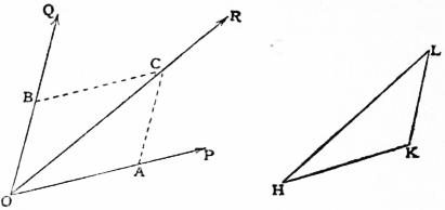
Fig. 1.
The fundamental postulate of this part of our subject is that the two forces acting on a particle may be compounded by the “parallelogram rule.” Thus, if the two forces P,Q be represented by the lines OA, OB, they can be replaced by a single force R represented by the diagonal OC of the parallelogram determined by OA, OB. This is of course a physical assumption whose propriety is justified solely by experience. We shall see later that it is implied in Newton’s statement of his Second Law of motion. In modern language, forces are compounded by “vector-addition”; thus, if we draw in succession vectors HK>, KL> to represent P, Q, the force R is represented by the vector HL> which is the “geometric sum” of HK>, KL>.
By successive applications of the above rule any number of forces acting on a particle may be replaced by a single force which is the vector-sum of the given forces: this single force is called the resultant. Thus if AB>, BC>, CD> ..., HK> be vectors representing the given forces, the resultant will be given by AK>. It will be understood that the figure ABCD ... K need not be confined to one plane.
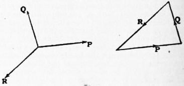
Fig. 2.
If, in particular, the point K coincides with A, so that the resultant vanishes, the given system of forces is said to be in equilibrium—i.e. the particle could remain permanently at rest under its action. This is the proposition known as the polygon of forces. In the particular case of three forces it reduces to the triangle of forces, viz. “If three forces acting on a particle are represented as to magnitude and direction by the sides of a triangle taken in order, they are in equilibrium.”
A sort of converse proposition is frequently useful, viz. if three forces acting on a particle be in equilibrium, and any triangle be constructed whose sides are respectively parallel to the forces, the magnitudes of the forces will be to one another as the corresponding sides of the triangle. This follows from the fact that all such triangles are necessarily similar.
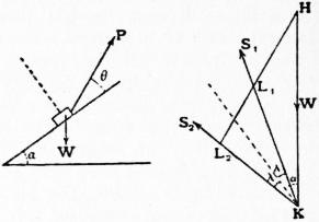
Fig. 3.
As a simple example of the geometrical method of treating statical problems we may consider the equilibrium of a particle on a “rough” inclined plane. The usual empirical law of sliding friction is that the mutual action between two plane surfaces in contact, or between a particle and a curve or surface, cannot make with the normal an angle exceeding a certain limit λ called the angle of friction. If the conditions of equilibrium require an obliquity greater than this, sliding will take place. The precise value of λ will vary with the nature and condition of the surfaces in contact. In the case of a body simply resting on an inclined plane, the reaction must of course be vertical, for equilibrium, and the slope α of the plane must therefore not exceed λ. For this reason λ is also known as the angle of repose. If α > λ, a force P must be applied in order to maintain equilibrium; let θ be the inclination of P to the plane, as shown in the left-hand diagram. The relations between this force P, the gravity W of the body, and the reaction S of the plane are then determined by a triangle of forces HKL. Since the inclination of S to the normal cannot exceed λ on either side, the value of P must lie between two limits which are represented by L1H, L2H, in the right-hand diagram. Denoting these limits by P1, P2, we have
P1/W = L1H/HK = sin (α − λ)/cos (θ + λ), P2/W = L2H/HK = sin (α + λ)/cos (θ − λ).
It appears, moreover, that if θ be varied P will be least when L1H is at right angles to KL1, in which case P1 = W sin (α − λ), corresponding to θ = −λ.
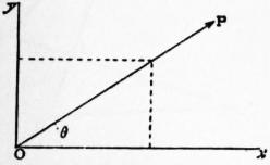
Just as two or more forces can be combined into a single resultant, so a single force may be resolved into components acting in assigned directions. Thus a force can be uniquely resolved into two components acting in two assigned directions in the same plane with it by an inversion of the parallelogram construction of fig. 1. If, as is usually most convenient, the two assigned directions are at right angles, the two components of a force P will be P cos θ, P sin θ, where θ is the inclination of P to the direction of the former component. This leads to formulae for the analytical reduction of a system of coplanar forces acting on a particle. Adopting rectangular axes Ox, Oy, in the plane of the forces, and distinguishing the various forces of the system by suffixes, we can replace the system by two forces X, Y, in the direction of co-ordinate axes; viz.—
X = P1 cos θ1 + P2 cos θ2 + ... = Σ (P cos θ), Y = P1 sin θ1 + P2 sin θ2 + ... = Σ (P sin θ).
(1)
These two forces X, Y, may be combined into a single resultant R making an angle φ with Ox, provided
X = R cos φ, Y = R sin φ,
(2)
whence
R2 = X2 + Y2, tan φ = Y/X.
(3)
For equilibrium we must have R = 0, which requires X = 0, Y = 0; in words, the sum of the components of the system must be zero for each of two perpendicular directions in the plane.
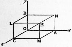
Fig. 5.
A similar procedure applies to a three-dimensional system. Thus if, O being the origin, OH> represent any force P of the system, the planes drawn through H parallel to the co-ordinate planes will enclose with the latter a parallelepiped, and it is evident that OH> is the geometric sum of OA>, AN>, NH>, or OA>, OB>, OC>, in the figure. Hence P is equivalent to three forces Pl, Pm, Pn acting along Ox, Oy, Oz, respectively, where l, m, n, are the “direction-ratios” of OH>. The whole system can be reduced in this way to three forces
X = Σ (Pl), Y = Σ (Pm), Z = Σ (Pn),
(4)
acting along the co-ordinate axes. These can again be combined into a single resultant R acting in the direction (λ, μ, ν), provided
X = Rλ, Y = Rμ, Z = Rν.
(5)
If the axes are rectangular, the direction-ratios become direction-cosines, so that λ2 + μ2 + ν2 = 1, whence
R2 = X2 + Y2 + Z2.
(6)
The conditions of equilibrium are X = 0, Y = 0, Z = 0.
§ 2. Statics of a System of Particles.—We assume that the mutual forces between the pairs of particles, whatever their nature, are subject to the “Law of Action and Reaction” (Newton’s Third Law); i.e. the force exerted by a particle A on a particle B, and the force exerted by B on A, are equal and opposite in the line AB. The problem of determining the possible configurations of equilibrium of a system of particles subject to extraneous forces which are known functions of the positions of the particles, and to internal forces which are known functions of the distances of the pairs of particles between which they act, is in general determinate. For if n be the number of particles, the 3n conditions of equilibrium (three for each particle) are equal in number to the 3n Cartesian (or other) co-ordinates of the particles, which are to be found. If the system be subject to frictionless constraints, e.g. if some of the particles be constrained to lie on smooth surfaces, or if pairs of particles be connected by inextensible strings, then for each geometrical relation thus introduced we have an unknown reaction (e.g. the pressure of the smooth surface, or the tension of the string), so that the problem is still determinate.
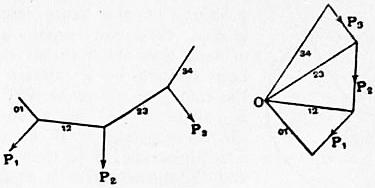
Fig. 6.
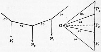
Fig. 7.
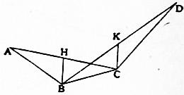
Fig. 8.
The case of the funicular polygon will be of use to us later. A number of particles attached at various points of a string are acted on by given extraneous forces P1, P2, P3 ... respectively. The relation between the three forces acting on any particle, viz. the extraneous force and the tensions in the two adjacent portions of the string can be exhibited by means of a triangle of forces; and if the successive triangles be drawn to the same scale they can be fitted together so as to constitute a single force-diagram, as shown in fig. 6. This diagram consists of a polygon whose successive sides represent the given forces P1, P2, P3 ..., and of a series of lines connecting the vertices with a point O. These latter lines measure the tensions in the successive portions of string. As a special, but very important case, the forces P1, P2, P3 ... may be parallel, e.g. they may be the weights of the several particles. The polygon of forces is then made up of segments of a vertical line. We note that the tensions have now the same horizontal projection (represented by the dotted line in fig. 7). It is further of interest to note that if the weights be all equal, and at equal horizontal intervals, the vertices of the funicular will lie on a parabola whose axis is vertical. To prove this statement, let A, B, C, D ... be successive vertices, and let H, K ... be the middle points of AC, BD ...; then BH, CK ... will be vertical by the hypothesis, and since the geometric sum of BA>, BC> is represented by 2BH>, the tension in BA: tension in BC: weight at B
as BA : BC : 2BH.
The tensions in the successive portions of the string are therefore proportional to the respective lengths, and the lines BH, CK ... are all equal. Hence AD, BC are parallel and are bisected by the same vertical line; and a parabola with vertical axis can therefore be described through A, B, C, D. The same holds for the four points B, C, D, E and so on; but since a parabola is uniquely determined by the direction of its axis and by three points on the curve, the successive parabolas ABCD, BCDE, CDEF ... must be coincident.
§ 3. Plane Kinematics of a Rigid Body.—The ideal rigid body is one in which the distance between any two points is invariable. For the present we confine ourselves to the consideration of displacements in two dimensions, so that the body is adequately represented by a thin lamina or plate.
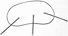
Fig. 9.
The position of a lamina movable in its own plane is determinate when we know the positions of any two points A, B of it. Since the four co-ordinates (Cartesian or other) of these two points are connected by the relation which expresses the invariability of the length AB, it is plain that virtually three independent elements are required and suffice to specify the position of the lamina. For instance, the lamina may in general be fixed by connecting any three points of it by rigid links to three fixed points in its plane. The three independent elements may be chosen in a variety of ways (e.g. they may be the lengths of the three links in the above example). They may be called (in a generalized sense) the co-ordinates of the lamina. The lamina when perfectly free to move in its own plane is said to have three degrees of freedom.
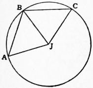
Fig. 10.
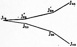
Fig. 11.
By a theorem due to M. Chasles any displacement whatever of the lamina in its own plane is equivalent to a rotation about some finite or infinitely distant point J. For suppose that in consequence of the displacement a point of the lamina is brought from A to B, whilst the point of the lamina which was originally at B is brought to C. Since AB, BC, are two different positions of the same line in the lamina they are equal, and it is evident that the rotation could have been effected by a rotation about J, the centre of the circle ABC, through an angle AJB. As a special case the three points A, B, C may be in a straight line; J is then at infinity and the displacement is equivalent to a pure translation, since every point of the lamina is now displaced parallel to AB through a space equal to AB.
Next, consider any continuous motion of the lamina. The latter may be brought from any one of its positions to a neighbouring one by a rotation about the proper centre. The limiting position J of this centre, when the two positions are taken infinitely close to one another, is called the instantaneous centre. If P, P′ be consecutive positions of the same point, and δθ the corresponding angle of rotation, then ultimately PP′ is at right angles to JP and equal to JP·δθ. The instantaneous centre will have a certain locus in space, and a certain locus in the lamina. These two loci are called pole-curves or centrodes, and are sometimes distinguished as the space-centrode and the body-centrode, respectively. In the continuous motion in question the latter curve rolls without slipping on the former (M. Chasles). Consider in fact any series of successive positions 1, 2, 3... of the lamina (fig. 11); and let J12, J23, J34... be the positions in space of the centres of the rotations by which the lamina can be brought from the first position to the second, from the second to the third, and so on. Further, in the position 1, let J12, J′23, J′34 ... be the points of the lamina which have become the successive centres of rotation. The given series of positions will be assumed in succession if we imagine the lamina to rotate first about J12 until J′23 comes into coincidence with J23, then about J23 until J′34 comes into coincidence with J34, and so on. This is equivalent to imagining the polygon J12 J′23 J′34 ..., supposed fixed in the lamina, to roll on the polygon J12 J23 J34 ..., which is supposed fixed in space. By imagining the successive positions to be taken infinitely close to one another we derive the theorem stated. The particular case where both centrodes are circles is specially important in mechanism.
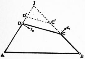
Fig. 12.
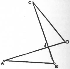
Fig. 13.
The theory may be illustrated by the case of “three-bar motion.” Let ABCD be any quadrilateral formed of jointed links. If, AB being held fixed, the quadrilateral be slightly deformed, it is obvious that the instantaneous centre J will be at the intersection of the straight lines AD, BC, since the displacements of the points D, C are necessarily at right angles to AD, BC, respectively. Hence these displacements are proportional to JD, JC, and therefore to DD′ CC′, where C′D′ is any line drawn parallel to CD, meeting BC, AD in C′, D′, respectively. The determination of the centrodes in three-bar motion is in general complicated, but in one case, that of the “crossed parallelogram” (fig. 13), they assume simple forms. We then have AB = DC and AD = BC, and from the symmetries of the figure it is plain that
AJ + JB = CJ + JD = AD.
Hence the locus of J relative to AB, and the locus relative to CD are equal ellipses of which A, B and C, D are respectively the foci. It may be noticed that the lamina in fig. 9 is not, strictly speaking, fixed, but admits of infinitesimal displacement, whenever the directions of the three links are concurrent (or parallel).
The matter may of course be treated analytically, but we shall only require the formula for infinitely small displacements. If the origin of rectangular axes fixed in the lamina be shifted through a space whose projections on the original directions of the axes are λ, μ, and if the axes are simultaneously turned through an angle ε, the co-ordinates of a point of the lamina, relative to the original axes, are changed from x, y to λ + x cos ε − y sin ε, μ + x sin ε + y cos ε, or λ + x − yε, μ + xε + y, ultimately. Hence the component displacements are ultimately
δx = λ − yε, δy = μ + xε
(1)
If we equate these to zero we get the co-ordinates of the instantaneous centre.
§ 4. Plane Statics.—The statics of a rigid body rests on the following two assumptions:—
(i) A force may be supposed to be applied indifferently at any point in its line of action. In other words, a force is of the nature of a “bound” or “localized” vector; it is regarded as resident in a certain line, but has no special reference to any particular point of the line.
(ii) Two forces in intersecting lines may be replaced by a force which is their geometric sum, acting through the intersection. The theory of parallel forces is included as a limiting case. For if O, A, B be any three points, and m, n any scalar quantities, we have in vectors
m · OA> + n · OB> = (m + n) OC>,
(1)
provided
m · CA> + n · CB> = 0.
(2)
Hence if forces P, Q act in OA, OB, the resultant R will pass through C, provided
m = P/OA, n = Q/OB;
also
R = P·OC/OA + Q·OC/OB,
(3)
and
P · AC : Q·CB = OA : OB.
(4)
These formulae give a means of constructing the resultant by means of any transversal AB cutting the lines of action. If we now imagine the point O to recede to infinity, the forces P, Q and the resultant R are parallel, and we have
R = P + Q, P·AC = Q·CB.
(5)
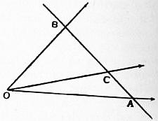
Fig. 14.
When P, Q have opposite signs the point C divides AB externally on the side of the greater force. The investigation fails when P + Q = 0, since it leads to an infinitely small resultant acting in an infinitely distant line. A combination of two equal, parallel, but oppositely directed forces cannot in fact be replaced by anything simpler, and must therefore be recognized as an independent entity in statics. It was called by L. Poinsot, who first systematically investigated its properties, a couple.
We now restrict ourselves for the present to the systems of forces in one plane. By successive applications of (ii) any such coplanar system can in general be reduced to a single resultant acting in a definite line. As exceptional cases the system may reduce to a couple, or it may be in equilibrium.
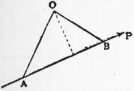
Fig. 15.
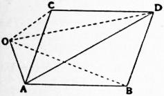
Fig. 16.
The moment of a force about a point O is the product of the force into the perpendicular drawn to its line of action from O, this perpendicular being reckoned positive or negative according as O lies on one side or other of the line of action. If we mark off a segment AB along the line of action so as to represent the force completely, the moment is represented as to magnitude by twice the area of the triangle OAB, and the usual convention as to sign is that the area is to be reckoned positive or negative according as the letters O, A, B, occur in “counter-clockwise” or “clockwise” order.
The sum of the moments of two forces about any point O is equal to the moment of their resultant (P. Varignon, 1687). Let AB, AC (fig. 16) represent the two forces, AD their resultant; we have to prove that the sum of the triangles OAB, OAC is equal to the triangle OAD, regard being had to signs. Since the side OA is common, we have to prove that the sum of the perpendiculars from B and C on OA is equal to the perpendicular from D on OA, these perpendiculars being reckoned positive or negative according as they lie to the right or left of AO. Regarded as a statement concerning the orthogonal projections of the vectors AB> and AC> (or BD), and of their sum AD>, on a line perpendicular to AO, this is obvious.
It is now evident that in the process of reduction of a coplanar system no change is made at any stage either in the sum of the projections of the forces on any line or in the sum of their moments about any point. It follows that the single resultant to which the system in general reduces is uniquely determinate, i.e. it acts in a definite line and has a definite magnitude and sense. Again it is necessary and sufficient for equilibrium that the sum of the projections of the forces on each of two perpendicular directions should vanish, and (moreover) that the sum of the moments about some one point should be zero. The fact that three independent conditions must hold for equilibrium is important. The conditions may of course be expressed in different (but equivalent) forms; e.g. the sum of the moments of the forces about each of the three points which are not collinear must be zero.
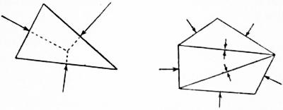
Fig. 17.
The particular case of three forces is of interest. If they are not all parallel they must be concurrent, and their vector-sum must be zero. Thus three forces acting perpendicular to the sides of a triangle at the middle points will be in equilibrium provided they are proportional to the respective sides, and act all inwards or all outwards. This result is easily extended to the case of a polygon of any number of sides; it has an important application in hydrostatics.
Again, suppose we have a bar AB resting with its ends on two smooth inclined planes which face each other. Let G be the centre of gravity (§ 11), and let AG = a, GB = b. Let α, β be the inclinations of the planes, and θ the angle which the bar makes with the vertical. The position of equilibrium is determined by the consideration that the reactions at A and B, which are by hypothesis normal to the planes, must meet at a point J on the vertical through G. Hence
JG/a = sin (θ − α) / sin α, JG/b = sin (θ + β) / sin β,
whence
cot θ = a cot α − b cot β .
a + b
(6)
If the bar is uniform we have a = b, and
cot θ = 1⁄2 (cot α − cot β).
(7)
The problem of a rod suspended by strings attached to two points of it is virtually identical, the tensions of the strings taking the place of the reactions of the planes.
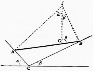
Fig. 18.
Just as a system of forces is in general equivalent to a single force, so a given force can conversely be replaced by combinations of other forces, in various ways. For instance, a given force (and consequently a system of forces) can be replaced in one and only one way by three forces acting in three assigned straight lines, provided these lines be not concurrent or parallel. Thus if the three lines form a triangle ABC, and if the given force F meet BC in H, then F can be resolved into two components acting in HA, BC, respectively. And the force in HA can be resolved into two components acting in BC, CA, respectively. A simple graphical construction is indicated in fig. 19, where the dotted lines are parallel. As an example, any system of forces acting on the lamina in fig. 9 is balanced by three determinate tensions (or thrusts) in the three links, provided the directions of the latter are not concurrent.
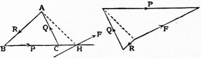
Fig. 19.
If P, Q, R, be any three forces acting along BC, CA, AB, respectively, the line of action of the resultant is determined by the consideration that the sum of the moments about any point on it must vanish. Hence in “trilinear” co-ordinates, with ABC as fundamental triangle, its equation is Pα + Qβ + Rγ = 0. If P : Q : R = a : b : c, where a, b, c are the lengths of the sides, this becomes the “line at infinity,” and the forces reduce to a couple.
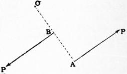
Fig. 20.
The sum of the moments of the two forces of a couple is the same about any point in the plane. Thus in the figure the sum of the moments about O is P·OA − P·OB or P·AB, which is independent of the position of O. This sum is called the moment of the couple; it must of course have the proper sign attributed to it. It easily follows that any two couples of the same moment are equivalent, and that any number of couples can be replaced by a single couple whose moment is the sum of their moments. Since a couple is for our purposes sufficiently represented by its moment, it has been proposed to substitute the name torque (or twisting effort), as free from the suggestion of any special pair of forces.
A system of forces represented completely by the sides of a plane polygon taken in order is equivalent to a couple whose moment is represented by twice the area of the polygon; this is proved by taking moments about any point. If the polygon intersects itself, care must be taken to attribute to the different parts of the area their proper signs.
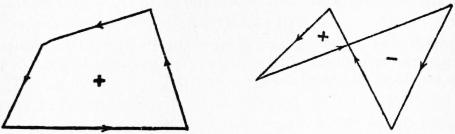
Fig. 21.
Again, any coplanar system of forces can be replaced by a single force R acting at any assigned point O, together with a couple G. The force R is the geometric sum of the given forces, and the moment (G) of the couple is equal to the sum of the moments of the given forces about O. The value of G will in general vary with the position of O, and will vanish when O lies on the line of action of the single resultant.
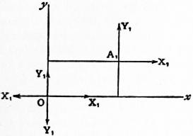
Fig. 22.
The formal analytical reduction of a system of coplanar forces is as follows. Let (x1, y1), (x2, y2), ... be the rectangular co-ordinates of any points A1, A2, ... on the lines of action of the respective forces. The force at A1 may be replaced by its components X1, Y1, parallel to the co-ordinate axes; that at A2 by its components X2, Y2, and so on. Introducing at O two equal and opposite forces ±X1 in Ox, we see that X1 at A1 may be replaced by an equal and parallel force at O together with a couple −y1X1. Similarly the force Y1 at A1 may be replaced by a force Y1 at O together with a couple x1Y1. The forces X1, Y1, at O can thus be transferred to O provided we introduce a couple x1Y1 − y1X1. Treating the remaining forces in the same way we get a force X1 + X2 + ... or Σ(X) along Ox, a force Y1 + Y2 + ... or Σ(Y) along Oy, and a couple (x1Y1 − y1X1) + (x2Y2 − y2X2) + ... or Σ(xY − yX). The three conditions of equilibrium are therefore
Σ(X) = 0, Σ(Y) = 0, Σ(xY − yX) = 0.
(8)
If O′ be a point whose co-ordinates are (ξ, η), the moment of the couple when the forces are transferred to O′ as a new origin will be Σ{(x − ξ) Y − (y − η) X}. This vanishes, i.e. the system reduces to a single resultant through O′, provided
−ξ·Σ(Y) + η·Σ(X) + Σ(xY − yX) = 0.
(9)
If ξ, η be regarded as current co-ordinates, this is the equation of the line of action of the single resultant to which the system is in general reducible.
If the forces are all parallel, making say an angle θ with Ox, we may write X1 = P1 cos θ, Y1 = P1 sin θ, X2 = P2 cos θ, Y2 = P2 sin θ, .... The equation (9) then becomes
{Σ(xP) − ξ·Σ(P)} sin θ − {Σ(yP) − η·Σ(P)} cos θ = 0.
(10)
If the forces P1, P2, ... be turned in the same sense through the same angle about the respective points A1, A2, ... so as to remain parallel, the value of θ is alone altered, and the resultant Σ(P) passes always through the point
x = Σ(xP) , y = Σ(yP) ,
Σ(P) Σ(P)
(11)
which is determined solely by the configuration of the points A1, A2, ... and by the ratios P1 : P2 : ... of the forces acting at them respectively. This point is called the centre of the given system of parallel forces; it is finite and determinate unless Σ(P) = 0. A geometrical proof of this theorem, which is not restricted to a two-dimensional system, is given later (§ 11). It contains the theory of the centre of gravity as ordinarily understood. For if we have an assemblage of particles whose mutual distances are small compared with the dimensions of the earth, the forces of gravity on them constitute a system of sensibly parallel forces, sensibly proportional to the respective masses. If now the assemblage be brought into any other position relative to the earth, without alteration of the mutual distances, this is equivalent to a rotation of the directions of the forces relatively to the assemblage, the ratios of the forces remaining unaltered. Hence there is a certain point, fixed relatively to the assemblage, through which the resultant of gravitational action always passes; this resultant is moreover equal to the sum of the forces on the several particles.
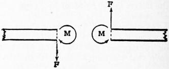
Fig. 23.
The theorem that any coplanar system of forces can be reduced to a force acting through any assigned point, together with a couple, has an important illustration in the theory of the distribution of shearing stress and bending moment in a horizontal beam, or other structure, subject to vertical extraneous forces. If we consider any vertical section P, the forces exerted across the section by the portion of the structure on one side on the portion on the other may be reduced to a vertical force F at P and a couple M. The force measures the shearing stress, and the couple the bending moment at P; we will reckon these quantities positive when the senses are as indicated in the figure.
If the remaining forces acting on the portion of the structure on either side of P are known, then resolving vertically we find F, and taking moments about P we find M. Again if PQ be any segment of the beam which is free from load, Q lying to the right of P, we find
FP = FQ, MP − MQ = −F·PQ;
(12)
hence F is constant between the loads, whilst M decreases as we travel to the right, with a constant gradient −F. If PQ be a short segment containing an isolated load W, we have
FQ − FP = −W, MQ = MP;
(13)
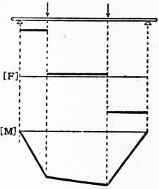
Fig. 24.
hence F is discontinuous at a concentrated load, diminishing by an amount equal to the load as we pass the loaded point to the right, whilst M is continuous. Accordingly the graph of F for any system of isolated loads will consist of a series of horizontal lines, whilst that of M will be a continuous polygon.
To pass to the case of continuous loads, let x be measured horizontally along the beam to the right. The load on an element δx of the beam may be represented by wδx, where w is in general a function of x. The equations (12) are now replaced by
δF = −wδx, δM = −Fδx,
whence
FQ − FP = − ∫QP w dx, MQ − MP = − ∫QP F dx.
(14)
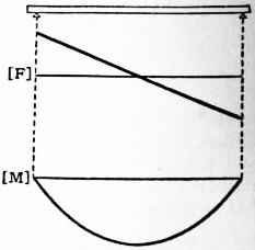
Fig. 25.
The latter relation shows that the bending moment varies as the area cut off by the ordinate in the graph of F. In the case of uniform load we have
F = −wx + A, M = 1⁄2wx2 − Ax + B,
(15)
where the arbitrary constants A,B are to be determined by the conditions of the special problem, e.g. the conditions at the ends of the beam. The graph of F is a straight line; that of M is a parabola with vertical axis. In all cases the graphs due to different distributions of load may be superposed. The figure shows the case of a uniform heavy beam supported at its ends.
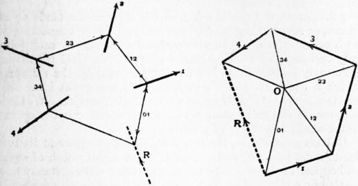
Fig. 26.
§ 5. Graphical Statics.—A graphical method of reducing a plane system of forces was introduced by C. Culmann (1864). It involves the construction of two figures, a force-diagram and a funicular polygon. The force-diagram is constructed by placing end to end a series of vectors representing the given forces in magnitude and direction, and joining the vertices of the polygon thus formed to an arbitrary pole O. The funicular or link polygon has its vertices on the lines of action of the given forces, and its sides respectively parallel to the lines drawn from O in the force-diagram; in particular, the two sides meeting in any vertex are respectively parallel to the lines drawn from O to the ends of that side of the force-polygon which represents the corresponding force. The relations will be understood from the annexed diagram, where corresponding lines in the force-diagram (to the right) and the funicular (to the left) are numbered similarly. The sides of the force-polygon may in the first instance be arranged in any order; the force-diagram can then be completed in a doubly infinite number of ways, owing to the arbitrary position of O; and for each force-diagram a simply infinite number of funiculars can be drawn. The two diagrams being supposed constructed, it is seen that each of the given systems of forces can be replaced by two components acting in the sides of the funicular which meet at the corresponding vertex, and that the magnitudes of these components will be given by the corresponding triangle of forces in the force-diagram; thus the force 1 in the figure is equivalent to two forces represented by 01 and 12. When this process of replacement is complete, each terminated side of the funicular is the seat of two forces which neutralize one another, and there remain only two uncompensated forces, viz., those resident in the first and last sides of the funicular. If these sides intersect, the resultant acts through the intersection, and its magnitude and direction are given by the line joining the first and last sides of the force-polygon (see fig. 26, where the resultant of the four given forces is denoted by R). As a special case it may happen that the force-polygon is closed, i.e. its first and last points coincide; the first and last sides of the funicular will then be parallel (unless they coincide), and the two uncompensated forces form a couple. If, however, the first and last sides of the funicular coincide, the two outstanding forces neutralize one another, and we have equilibrium. Hence the necessary and sufficient conditions of equilibrium are that the force-polygon and the funicular should both be closed. This is illustrated by fig. 26 if we imagine the force R, reversed, to be included in the system of given forces.
It is evident that a system of jointed bars having the shape of the funicular polygon would be in equilibrium under the action of the given forces, supposed applied to the joints; moreover any bar in which the stress is of the nature of a tension (as distinguished from a thrust) might be replaced by a string. This is the origin of the names “link-polygon” and “funicular” (cf. § 2).
If funiculars be drawn for two positions O, O′ of the pole in the force-diagram, their corresponding sides will intersect on a straight line parallel to OO′. This is essentially a theorem of projective geometry, but the following statical proof is interesting. Let AB (fig. 27) be any side of the force-polygon, and construct the corresponding portions of the two diagrams, first with O and then with O′ as pole. The force corresponding to AB may be replaced by the two components marked x, y; and a force corresponding to BA may be represented by the two components marked x′, y′. Hence the forces x, y, x′, y′ are in equilibrium. Now x, x′ have a resultant through H, represented in magnitude and direction by OO′, whilst y, y′ have a resultant through K represented in magnitude and direction by O′O. Hence HK must be parallel to OO′. This theorem enables us, when one funicular has been drawn, to construct any other without further reference to the force-diagram.
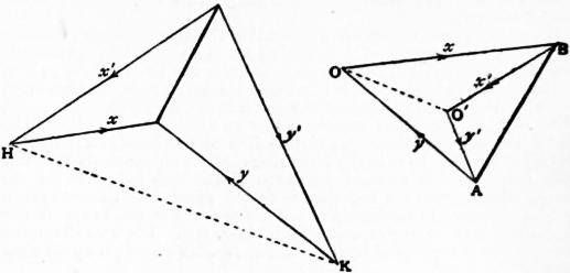
Fig. 27.
The complete figures obtained by drawing first the force-diagrams of a system of forces in equilibrium with two distinct poles O, O′, and secondly the corresponding funiculars, have various interesting relations. In the first place, each of these figures may be conceived as an orthogonal projection of a closed plane-faced polyhedron. As regards the former figure this is evident at once; viz. the polyhedron consists of two pyramids with vertices represented by O, O′, and a common base whose perimeter is represented by the force-polygon (only one of these is shown in fig. 28). As regards the funicular diagram, let LM be the line on which the pairs of corresponding sides of the two polygons meet, and through it draw any two planes ω, ω′. Through the vertices A, B, C, ... and A′, B′, C′, ... of the two funiculars draw normals to the plane of the diagram, to meet ω and ω′ respectively. The points thus obtained are evidently the vertices of a polyhedron with plane faces.
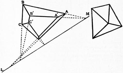
Fig. 28.
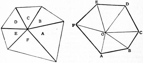
Fig. 29.
To every line in either of the original figures corresponds of course a parallel line in the other; moreover, it is seen that concurrent lines in either figure correspond to lines forming a closed polygon in the other. Two plane figures so related are called reciprocal, since the properties of the first figure in relation to the second are the same as those of the second with respect to the first. A still simpler instance of reciprocal figures is supplied by the case of concurrent forces in equilibrium (fig. 29). The theory of these reciprocal figures was first studied by J. Clerk Maxwell, who showed amongst other things that a reciprocal can always be drawn to any figure which is the orthogonal projection of a plane-faced polyhedron. If in fact we take the pole of each face of such a polyhedron with respect to a paraboloid of revolution, these poles will be the vertices of a second polyhedron whose edges are the “conjugate lines” of those of the former. If we project both polyhedra orthogonally on a plane perpendicular to the axis of the paraboloid, we obtain two figures which are reciprocal, except that corresponding lines are orthogonal instead of parallel. Another proof will be indicated later (§ 8) in connexion with the properties of the linear complex. It is convenient to have a notation which shall put in evidence the reciprocal character. For this purpose we may designate the points in one figure by letters A, B, C, ... and the corresponding polygons in the other figure by the same letters; a line joining two points A, B in one figure will then correspond to the side common to the two polygons A, B in the other. This notation was employed by R. H. Bow in connexion with the theory of frames (§ 6, and see also Applied Mechanics below) where reciprocal diagrams are frequently of use (cf. Diagram).
When the given forces are all parallel, the force-polygon consists of a series of segments of a straight line. This case has important practical applications; for instance we may use the method to find the pressures on the supports of a beam loaded in any given manner. Thus if AB, BC, CD represent the given loads, in the force-diagram, we construct the sides corresponding to OA, OB, OC, OD in the funicular; we then draw the closing line of the funicular polygon, and a parallel OE to it in the force diagram. The segments DE, EA then represent the upward pressures of the two supports on the beam, which pressures together with the given loads constitute a system of forces in equilibrium. The pressures of the beam on the supports are of course represented by ED, AE. The two diagrams are portions of reciprocal figures, so that Bow’s notation is applicable.
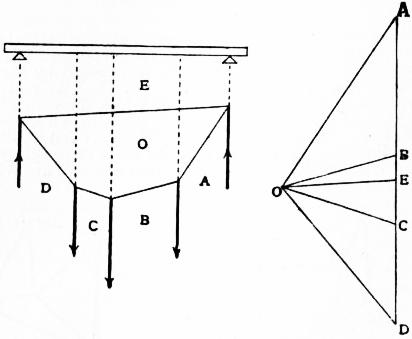
Fig. 30.
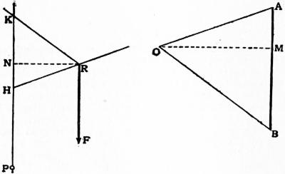
Fig. 31.
A graphical method can also be applied to find the moment of a force, or of a system of forces, about any assigned point P. Let F be a force represented by AB in the force-diagram. Draw a parallel through P to meet the sides of the funicular which correspond to OA, OB in the points H, K. If R be the intersection of these sides, the triangles OAB, RHK are similar, and if the perpendiculars OM, RN be drawn we have
HK·OM = AB·RN = F·RN,
which is the moment of F about P. If the given forces are all parallel (say vertical) OM is the same for all, and the moments of the several forces about P are represented on a certain scale by the lengths intercepted by the successive pairs of sides on the vertical through P. Moreover, the moments are compounded by adding (geometrically) the corresponding lengths HK. Hence if a system of vertical forces be in equilibrium, so that the funicular polygon is closed, the length which this polygon intercepts on the vertical through any point P gives the sum of the moments about P of all the forces on one side of this vertical. For instance, in the case of a beam in equilibrium under any given loads and the reactions at the supports, we get a graphical representation of the distribution of bending moment over the beam. The construction in fig. 30 can easily be adjusted so that the closing line shall be horizontal; and the figure then becomes identical with the bending-moment diagram of § 4. If we wish to study the effects of a movable load, or system of loads, in different positions on the beam, it is only necessary to shift the lines of action of the pressures of the supports relatively to the funicular, keeping them at the same, distance apart; the only change is then in the position of the closing line of the funicular. It may be remarked that since this line joins homologous points of two “similar” rows it will envelope a parabola.
The “centre” (§ 4) of a system of parallel forces of given magnitudes, acting at given points, is easily determined graphically. We have only to construct the line of action of the resultant for each of two arbitrary directions of the forces; the intersection of the two lines gives the point required. The construction is neatest if the two arbitrary directions are taken at right angles to one another.
§ 6. Theory of Frames.—A frame is a structure made up of pieces, or members, each of which has two joints connecting it with other members. In a two-dimensional frame, each joint may be conceived as consisting of a small cylindrical pin fitting accurately and smoothly into holes drilled through the members which it connects. This supposition is a somewhat ideal one, and is often only roughly approximated to in practice. We shall suppose, in the first instance, that extraneous forces act on the frame at the joints only, i.e. on the pins.
On this assumption, the reactions on any member at its two joints must be equal and opposite. This combination of equal and opposite forces is called the stress in the member; it may be a tension or a thrust. For diagrammatic purposes each member is sufficiently represented by a straight line terminating at the two joints; these lines will be referred to as the bars of the frame.
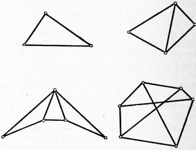
Fig. 32.
In structural applications a frame must be stiff, or rigid, i.e. it must be incapable of deformation without alteration of length in at least one of its bars. It is said to be just rigid if it ceases to be rigid when any one of its bars is removed. A frame which has more bars than are essential for rigidity may be called over-rigid; such a frame is in general self-stressed, i.e. it is in a state of stress independently of the action of extraneous forces. A plane frame of n joints which is just rigid (as regards deformation in its own plane) has 2n − 3 bars, for if one bar be held fixed the 2(n − 2) co-ordinates of the remaining n − 2 joints must just be determined by the lengths of the remaining bars. The total number of bars is therefore 2(n − 2) + 1. When a plane frame which is just rigid is subject to a given system of equilibrating extraneous forces (in its own plane) acting on the joints, the stresses in the bars are in general uniquely determinate. For the conditions of equilibrium of the forces on each pin furnish 2n equations, viz. two for each point, which are linear in respect of the stresses and the extraneous forces. This system of equations must involve the three conditions of equilibrium of the extraneous forces which are already identically satisfied, by hypothesis; there remain therefore 2n − 3 independent relations to determine the 2n − 3 unknown stresses. A frame of n joints and 2n − 3 bars may of course fail to be rigid owing to some parts being over-stiff whilst others are deformable; in such a case it will be found that the statical equations, apart from the three identical relations imposed by the equilibrium of the extraneous forces, are not all independent but are equivalent to less than 2n − 3 relations. Another exceptional case, known as the critical case, will be noticed later (§ 9).
A plane frame which can be built up from a single bar by successive steps, at each of which a new joint is introduced by two new bars meeting there, is called a simple frame; it is obviously just rigid. The stresses produced by extraneous forces in a simple frame can be found by considering the equilibrium of the various joints in a proper succession; and if the graphical method be employed the various polygons of force can be combined into a single force-diagram. This procedure was introduced by W. J. M. Rankine and J. Clerk Maxwell (1864). It may be noticed that if we take an arbitrary pole in the force-diagram, and draw a corresponding funicular in the skeleton diagram which represents the frame together with the lines of action of the extraneous forces, we obtain two complete reciprocal figures, in Maxwell’s sense. It is accordingly convenient to use Bow’s notation (§ 5), and to distinguish the several compartments of the frame-diagram by letters. See fig. 33, where the successive triangles in the diagram of forces may be constructed in the order XYZ, ZXA, AZB. The class of “simple” frames includes many of the frameworks used in the construction of roofs, lattice girders and suspension bridges; a number of examples will be found in the article Bridges. By examining the senses in which the respective forces act at each joint we can ascertain which members are in tension and which are in thrust; in fig. 33 this is indicated by the directions of the arrowheads.
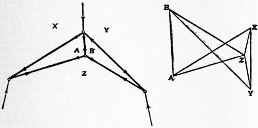
Fig. 33.
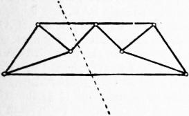
Fig. 34.
When a frame, though just rigid, is not “simple” in the above sense, the preceding method must be replaced, or supplemented, by one or other of various artifices. In some cases the method of sections is sufficient for the purpose. If an ideal section be drawn across the frame, the extraneous forces on either side must be in equilibrium with the forces in the bars cut across; and if the section can be drawn so as to cut only three bars, the forces in these can be found, since the problem reduces to that of resolving a given force into three components acting in three given lines (§ 4). The “critical case” where the directions of the three bars are concurrent is of course excluded. Another method, always available, will be explained under “Work” (§ 9).
When extraneous forces act on the bars themselves the stress in each bar no longer consists of a simple longitudinal tension or thrust. To find the reactions at the joints we may proceed as follows. Each extraneous force W acting on a bar may be replaced (in an infinite number of ways) by two components P, Q in lines through the centres of the pins at the extremities. In practice the forces W are usually vertical, and the components P, Q are then conveniently taken to be vertical also. We first alter the problem by transferring the forces P, Q to the pins. The stresses in the bars, in the problem as thus modified, may be supposed found by the preceding methods; it remains to infer from the results thus obtained the reactions in the original form of the problem. To find the pressure exerted by a bar AB on the pin A we compound with the force in AB given by the diagram a force equal to P. Conversely, to find the pressure of the pin A on the bar AB we must compound with the force given by the diagram a force equal and opposite to P. This question arises in practice in the theory of “three-jointed” structures; for the purpose in hand such a structure is sufficiently represented by two bars AB, BC. The right-hand figure represents a portion of the force-diagram; in particular ZX> represents the pressure of AB on B in the modified problem where the loads W1 and W2 on the two bars are replaced by loads P1, Q1, and P2, Q2 respectively, acting on the pins. Compounding with this XV>, which represents Q1, we get the actual pressure ZV> exerted by AB on B. The directions and magnitudes of the reactions at A and C are then easily ascertained. On account of its practical importance several other graphical solutions of this problem have been devised.
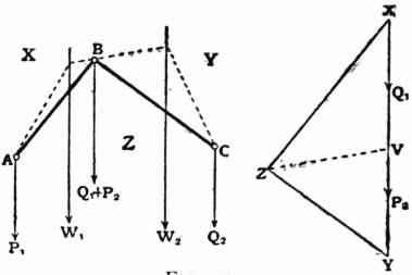
Fig. 35.
§ 7. Three-dimensional Kinematics of a Rigid Body.—The position of a rigid body is determined when we know the positions of three points A, B, C of it which are not collinear, for the position of any other point P is then determined by the three distances PA, PB, PC. The nine co-ordinates (Cartesian or other) of A, B, C are subject to the three relations which express the invariability of the distances BC, CA, AB, and are therefore equivalent to six independent quantities. Hence a rigid body not constrained in any way is said to have six degrees of freedom. Conversely, any six geometrical relations restrict the body in general to one or other of a series of definite positions, none of which can be departed from without violating the conditions in question. For instance, the position of a theodolite is fixed by the fact that its rounded feet rest in contact with six given plane surfaces. Again, a rigid three-dimensional frame can be rigidly fixed relatively to the earth by means of six links.
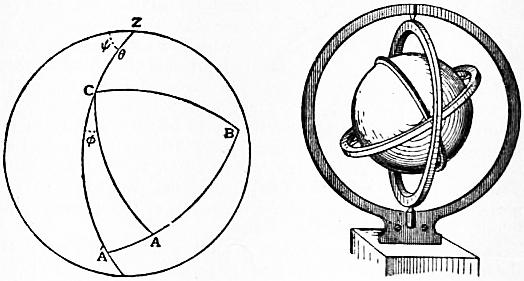
Fig. 36. Fig. 37.
The six independent quantities, or “co-ordinates,” which serve to specify the position of a rigid body in space may of course be chosen in an endless variety of ways. We may, for instance, employ the three Cartesian co-ordinates of a particular point O of the body, and three angular co-ordinates which express the orientation of the body with respect to O. Thus in fig. 36, if OA, OB, OC be three mutually perpendicular lines in the solid, we may denote by θ the angle which OC makes with a fixed direction OZ, by ψ the azimuth of the plane ZOC measured from some fixed plane through OZ, and by φ the inclination of the plane COA to the plane ZOC. In fig. 36 these various lines and planes are represented by their intersections with a unit sphere having O as centre. This very useful, although unsymmetrical, system of angular co-ordinates was introduced by L. Euler. It is exemplified in “Cardan’s suspension,” as used in connexion with a compass-bowl or a gyroscope. Thus in the gyroscope the “flywheel” (represented by the globe in fig. 37) can turn about a diameter OC of a ring which is itself free to turn about a diametral axis OX at right angles to the former; this axis is carried by a second ring which is free to turn about a fixed diameter OZ, which is at right angles to OX.
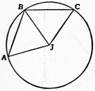
Fig. 10.
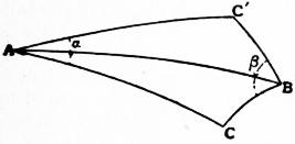
Fig. 38.
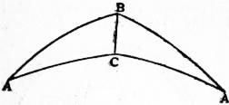
Fig. 39.
We proceed to sketch the theory of the finite displacements of a rigid body. It was shown by Euler (1776) that any displacement in which one point O of the body is fixed is equivalent to a pure rotation about some axis through O. Imagine two spheres of equal radius with O as their common centre, one fixed in the body and moving with it, the other fixed in space. In any displacement about O as a fixed point, the former sphere slides over the latter, as in a “ball-and-socket” joint. Suppose that as the result of the displacement a point of the moving sphere is brought from A to B, whilst the point which was at B is brought to C (cf. fig. 10). Let J be the pole of the circle ABC (usually a “small circle” of the fixed sphere), and join JA, JB, JC, AB, BC by great-circle arcs. The spherical isosceles triangles AJB, BJC are congruent, and we see that AB can be brought into the position BC by a rotation about the axis OJ through an angle AJB.
It is convenient to distinguish the two senses in which rotation may take place about an axis OA by opposite signs. We shall reckon a rotation as positive when it is related to the direction from O to A as the direction of rotation is related to that of translation in a right-handed screw. Thus a negative rotation about OA may be regarded as a positive rotation about OA′, the prolongation of AO. Now suppose that a body receives first a positive rotation α about OA, and secondly a positive rotation β about OB; and let A, B be the intersections of these axes with a sphere described about O as centre. If we construct the spherical triangles ABC, ABC′ (fig. 38), having in each case the angles at A and B equal to 1⁄2α and 1⁄2β respectively, it is evident that the first rotation will bring a point from C to C′ and that the second will bring it back to C; the result is therefore equivalent to a rotation about OC. We note also that if the given rotations had been effected in the inverse order, the axis of the resultant rotation would have been OC′, so that finite rotations do not obey the “commutative law.” To find the angle of the equivalent rotation, in the actual case, suppose that the second rotation (about OB) brings a point from A to A′. The spherical triangles ABC, A′BC (fig. 39) are “symmetrically equal,” and the angle of the resultant rotation, viz. ACA′, is 2π − 2C. This is equivalent to a negative rotation 2C about OC, whence the theorem that the effect of three successive positive rotations 2A, 2B, 2C about OA, OB, OC, respectively, is to leave the body in its original position, provided the circuit ABC is left-handed as seen from O. This theorem is due to O. Rodrigues (1840). The composition of finite rotations about parallel axes is a particular case of the preceding; the radius of the sphere is now infinite, and the triangles are plane.
In any continuous motion of a solid about a fixed point O, the limiting position of the axis of the rotation by which the body can be brought from any one of its positions to a consecutive one is called the instantaneous axis. This axis traces out a certain cone in the body, and a certain cone in space, and the continuous motion in question may be represented as consisting in a rolling of the former cone on the latter. The proof is similar to that of the corresponding theorem of plane kinematics (§ 3).
It follows from Euler’s theorem that the most general displacement of a rigid body may be effected by a pure translation which brings any one point of it to its final position O, followed by a pure rotation about some axis through O. Those planes in the body which are perpendicular to this axis obviously remain parallel to their original positions. Hence, if σ, σ′ denote the initial and final positions of any figure in one of these planes, the displacement could evidently have been effected by (1) a translation perpendicular to the planes in question, bringing σ into some position σ″ in the plane of σ′, and (2) a rotation about a normal to the planes, bringing σ″ into coincidence with σ (§ 3). In other words, the most general displacement is equivalent to a translation parallel to a certain axis combined with a rotation about that axis; i.e. it may be described as a twist about a certain screw. In particular cases, of course, the translation, or the rotation, may vanish.
The preceding theorem, which is due to Michel Chasles (1830), may be proved in various other interesting ways. Thus if a point of the body be displaced from A to B, whilst the point which was at B is displaced to C, and that which was at C to D, the four points A, B, C, D lie on a helix whose axis is the common perpendicular to the bisectors of the angles ABC, BCD. This is the axis of the required screw; the amount of the translation is measured by the projection of AB or BC or CD on the axis; and the angle of rotation is given by the inclination of the aforesaid bisectors. This construction was given by M. W. Crofton. Again, H. Wiener and W. Burnside have employed the half-turn (i.e. a rotation through two right angles) as the fundamental operation. This has the advantage that it is completely specified by the axis of the rotation, the sense being immaterial. Successive half-turns about parallel axes a, b are equivalent to a translation measured by double the distance between these axes in the direction from a to b. Successive half-turns about intersecting axes a, b are equivalent to a rotation about the common perpendicular to a, b at their intersection, of amount equal to twice the acute angle between them, in the direction from a to b. Successive half-turns about two skew axes a, b are equivalent to a twist about a screw whose axis is the common perpendicular to a, b, the translation being double the shortest distance, and the angle of rotation being twice the acute angle between a, b, in the direction from a to b. It is easily shown that any displacement whatever is equivalent to two half-turns and therefore to a screw.
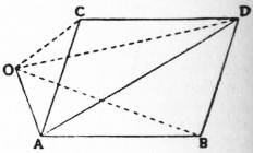
Fig. 16.
In mechanics we are specially concerned with the theory of infinitesimal displacements. This is included in the preceding, but it is simpler in that the various operations are commutative. An infinitely small rotation about any axis is conveniently represented geometrically by a length AB measures along the axis and proportional to the angle of rotation, with the convention that the direction from A to B shall be related to the rotation as is the direction of translation to that of rotation in a right-handed screw. The consequent displacement of any point P will then be at right angles to the plane PAB, its amount will be represented by double the area of the triangle PAB, and its sense will depend on the cyclical order of the letters P, A, B. If AB, AC represent infinitesimal rotations about intersecting axes, the consequent displacement of any point O in the plane BAC will be at right angles to this plane, and will be represented by twice the sum of the areas OAB, OAC, taken with proper signs. It follows by analogy with the theory of moments (§ 4) that the resultant rotation will be represented by AD, the vector-sum of AB, AC (see fig. 16). It is easily inferred as a limiting case, or proved directly, that two infinitesimal rotations α, β about parallel axes are equivalent to a rotation α + β about a parallel axis in the same plane with the two former, and dividing a common perpendicular AB in a point C so that AC/CB = β/α. If the rotations are equal and opposite, so that α + β = 0, the point C is at infinity, and the effect is a translation perpendicular to the plane of the two given axes, of amount α·AB. It thus appears that an infinitesimal rotation is of the nature of a “localized vector,” and is subject in all respects to the same mathematical laws as a force, conceived as acting on a rigid body. Moreover, that an infinitesimal translation is analogous to a couple and follows the same laws. These results are due to Poinsot.
The analytical treatment of small displacements is as follows. We first suppose that one point O of the body is fixed, and take this as the origin of a “right-handed” system of rectangular co-ordinates; i.e. the positive directions of the axes are assumed to be so arranged that a positive rotation of 90° about Ox would bring Oy into the position of Oz, and so on. The displacement will consist of an infinitesimal rotation ε about some axis through O, whose direction-cosines are, say, l, m, n. From the equivalence of a small rotation to a localized vector it follows that the rotation ε will be equivalent to rotations ξ, η, ζ about Ox, Oy, Oz, respectively, provided
ξ = lε, η = mε, ζ = nε,
(1)
and we note that
ξ2 + η2 + ζ2 = ε2.
(2)
Thus in the case of fig. 36 it may be required to connect the infinitesimal rotations ξ, η, ζ about OA, OB, OC with the variations of the angular co-ordinates θ, ψ, φ. The displacement of the point C of the body is made up of δθ tangential to the meridian ZC and sin θ δψ perpendicular to the plane of this meridian. Hence, resolving along the tangents to the arcs BC, CA, respectively, we have
ξ = δθ sin φ − sin θ δψ cos φ, η = δθ cos φ + sin θ δψ sin φ.
(3)
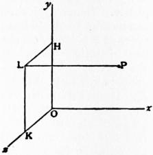
Fig. 40.
Again, consider the point of the solid which was initially at A′ in the figure. This is displaced relatively to A′ through a space δψ perpendicular to the plane of the meridian, whilst A′ itself is displaced through a space cos θ δψ in the same direction. Hence
ζ = δφ + cos θ δψ.
(4)
To find the component displacements of a point P of the body, whose co-ordinates are x, y, z, we draw PL normal to the plane yOz, and LH, LK perpendicular to Oy, Oz, respectively. The displacement of P parallel to Ox is the same as that of L, which is made up of ηz and −ζy. In this way we obtain the formulae
δx = ηz − ζy, δy = ζx − ξz, δz = ξy − ηx.
(5)
The most general case is derived from this by adding the component displacements λ, μ, ν (say) of the point which was at O; thus
δx = λ + ηz − ζy, δy = μ + ζx − ξz, δz = ν + ξy − ηx.
(6)
The displacement is thus expressed in terms of the six independent quantities ξ, η, ζ, λ, μ, ν. The points whose displacements are in the direction of the resultant axis of rotation are determined by δx : δy : δz = ξ : η : ζ, or
(λ + ηz − ζy)/ξ = (μ + ζx − ξz)/η = (ν + ξy − ηx)/ζ.
(7)
These are the equations of a straight line, and the displacement is in fact equivalent to a twist about a screw having this line as axis. The translation parallel to this axis is
lδx + mδy + nδz = (λξ + μη + νζ)/ε.
(8)
The linear magnitude which measures the ratio of translation to rotation in a screw is called the pitch. In the present case the pitch is
(λξ + μη + νζ) / (ξ2 + η2 + ζ2).
(9)
Since ξ2 + η2 + ζ2, or ε2, is necessarily an absolute invariant for all transformations of the (rectangular) co-ordinate axes, we infer that λξ + μη + νζ is also an absolute invariant. When the latter invariant, but not the former, vanishes, the displacement is equivalent to a pure rotation.
If the small displacements of a rigid body be subject to one constraint, e.g. if a point of the body be restricted to lie on a given surface, the mathematical expression of this fact leads to a homogeneous linear equation between the infinitesimals ξ, η, ζ, λ, μ, ν, say
Aξ + Bη + Cζ + Fλ + Gμ + Hν = 0.
(10)
The quantities ξ, η, ζ, λ, μ, ν are no longer independent, and the body has now only five degrees of freedom. Every additional constraint introduces an additional equation of the type (10) and reduces the number of degrees of freedom by one. In Sir R. S. Ball’s Theory of Screws an analysis is made of the possible displacements of a body which has respectively two, three, four, five degrees of freedom. We will briefly notice the case of two degrees, which involves an interesting generalization of the method (already explained) of compounding rotations about intersecting axes. We assume that the body receives arbitrary twists about two given screws, and it is required to determine the character of the resultant displacement. We examine first the case where the axes of the two screws are at right angles and intersect. We take these as axes of x and y; then if ξ, η be the component rotations about them, we have
λ = hξ, μ = kη, ν = 0,
(11)
where h, k, are the pitches of the two given screws. The equations (7) of the axis of the resultant screw then reduce to
x/ξ = y/η, z(ξ2 + η2) = (k − h) ξη.
(12)
Hence, whatever the ratio ξ : η, the axis of the resultant screw lies on the conoidal surface
z (x2 + y2) = cxy,
(13)
where c = 1⁄2(k − h). The co-ordinates of any point on (13) may be written
x = r cos θ, y = r sin θ, z = c sin 2θ;
(14)
hence if we imagine a curve of sines to be traced on a circular cylinder so that the circumference just includes two complete undulations, a straight line cutting the axis of the cylinder at right angles and meeting this curve will generate the surface. This is called a cylindroid. Again, the pitch of the resultant screw is
p = (λξ + μη) / (ξ2 + η2) = h cos2 θ + k sin2 θ.
(15)
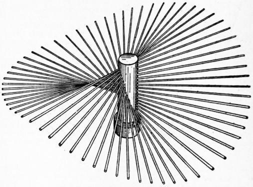
From Sir Robert S. Ball’s Theory of Screws.
Fig. 41.
The distribution of pitch among the various screws has therefore a simple relation to the pitch-conic
hx2 + ky2 = const;
(16)
viz. the pitch of any screw varies inversely as the square of that diameter of the conic which is parallel to its axis. It is to be noticed that the parameter c of the cylindroid is unaltered if the two pitches h, k be increased by equal amounts; the only change is that all the pitches are increased by the same amount. It remains to show that a system of screws of the above type can be constructed so as to contain any two given screws whatever. In the first place, a cylindroid can be constructed so as to have its axis coincident with the common perpendicular to the axes of the two given screws and to satisfy three other conditions, for the position of the centre, the parameter, and the orientation about the axis are still at our disposal. Hence we can adjust these so that the surface shall contain the axes of the two given screws as generators, and that the difference of the corresponding pitches shall have the proper value. It follows that when a body has two degrees of freedom it can twist about any one of a singly infinite system of screws whose axes lie on a certain cylindroid. In particular cases the cylindroid may degenerate into a plane, the pitches being then all equal.
§ 8. Three-dimensional Statics.—A system of parallel forces can be combined two and two until they are replaced by a single resultant equal to their sum, acting in a certain line. As special cases, the system may reduce to a couple, or it may be in equilibrium.
In general, however, a three-dimensional system of forces cannot be replaced by a single resultant force. But it may be reduced to simpler elements in a variety of ways. For example, it may be reduced to two forces in perpendicular skew lines. For consider any plane, and let each force, at its intersection with the plane, be resolved into two components, one (P) normal to the plane, the other (Q) in the plane. The assemblage of parallel forces P can be replaced in general by a single force, and the coplanar system of forces Q by another single force.
If the plane in question be chosen perpendicular to the direction of the vector-sum of the given forces, the vector-sum of the components Q is zero, and these components are therefore equivalent to a couple (§ 4). Hence any three-dimensional system can be reduced to a single force R acting in a certain line, together with a couple G in a plane perpendicular to the line. This theorem was first given by L. Poinsot, and the line of action of R was called by him the central axis of the system. The combination of a force and a couple in a perpendicular plane is termed by Sir R. S. Ball a wrench. Its type, as distinguished from its absolute magnitude, may be specified by a screw whose axis is the line of action of R, and whose pitch is the ratio G/R.
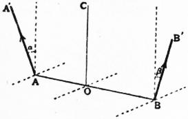
Fig. 42.
The case of two forces may be specially noticed. Let AB be the shortest distance between the lines of action, and let AA′, BB′ (fig. 42) represent the forces. Let α, β be the angles which AA′, BB′ make with the direction of the vector-sum, on opposite sides. Divide AB in O, so that
AA′ · cos α · AO = BB′ · cos β · OB,
(1)
and draw OC parallel to the vector-sum. Resolving AA′, BB′ each into two components parallel and perpendicular to OC, we see that the former components have a single resultant in OC, of amount
R = AA′ cos α + BB′ cos β,
(2)
whilst the latter components form a couple of moment
G = AA′ · AB · sin α = BB′ · AB · sin β.
(3)
Conversely it is seen that any wrench can be replaced in an infinite number of ways by two forces, and that the line of action of one of these may be chosen quite arbitrarily. Also, we find from (2) and (3) that
G · R = AA′ · BB′ · AB · sin (α + β).
(4)
The right-hand expression is six times the volume of the tetrahedron of which the lines AA′, BB′ representing the forces are opposite edges; and we infer that, in whatever way the wrench be resolved into two forces, the volume of this tetrahedron is invariable.
To define the moment of a force about an axis HK, we project the force orthogonally on a plane perpendicular to HK and take the moment of the projection about the intersection of HK with the plane (see § 4). Some convention as to sign is necessary; we shall reckon the moment to be positive when the tendency of the force is right-handed as regards the direction from H to K. Since two concurrent forces and their resultant obviously project into two concurrent forces and their resultant, we see that the sum of the moments of two concurrent forces about any axis HK is equal to the moment of their resultant. Parallel forces may be included in this statement as a limiting case. Hence, in whatever way one system of forces is by successive steps replaced by another, no change is made in the sum of the moments about any assigned axis. By means of this theorem we can show that the previous reduction of any system to a wrench is unique.
From the analogy of couples to translations which was pointed out in § 7, we may infer that a couple is sufficiently represented by a “free” (or non-localized) vector perpendicular to its plane. The length of the vector must be proportional to the moment of the couple, and its sense must be such that the sum of the moments of the two forces of the couple about it is positive. In particular, we infer that couples of the same moment in parallel planes are equivalent; and that couples in any two planes may be compounded by geometrical addition of the corresponding vectors. Independent statical proofs are of course easily given. Thus, let the plane of the paper be perpendicular to the planes of two couples, and therefore perpendicular to the line of intersection of these planes. By § 4, each couple can be replaced by two forces ±P (fig. 43) perpendicular to the plane of the paper, and so that one force of each couple is in the line of intersection (B); the arms (AB, BC) will then be proportional to the respective moments. The two forces at B will cancel, and we are left with a couple of moment P·AC in the plane AC. If we draw three vectors to represent these three couples, they will be perpendicular and proportional to the respective sides of the triangle ABC; hence the third vector is the geometric sum of the other two. Since, in this proof the magnitude of P is arbitrary, It follows incidentally that couples of the same moment in parallel planes, e.g. planes parallel to AC, are equivalent.
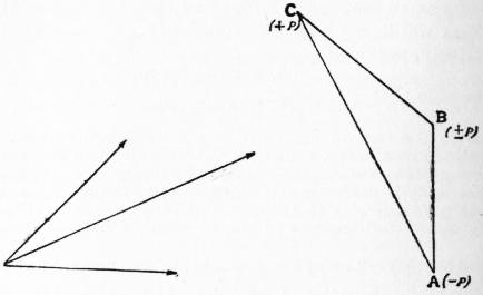
Fig. 43.
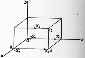
Fig. 44.
Hence a couple of moment G, whose axis has the direction (l, m, n) relative to a right-handed system of rectangular axes, is equivalent to three couples lG, mG, nG in the co-ordinate planes. The analytical reduction of a three-dimensional system can now be conducted as follows. Let (x1, y1, z1) be the co-ordinates of a point P1 on the line of action of one of the forces, whose components are (say) X1, Y1, Z1. Draw P1H normal to the plane zOx, and HK perpendicular to Oz. In KH introduce two equal and opposite forces ±X1. The force X1 at P1 with −X1 in KH forms a couple about Oz, of moment −y1X1. Next, introduce along Ox two equal and opposite forces ±X1. The force X1 in KH with −X1 in Ox forms a couple about Oy, of moment z1X1. Hence the force X1 can be transferred from P1 to O, provided we introduce couples of moments z1X1 about Oy and −y1X1, about Oz. Dealing in the same way with the forces Y1, Z1 at P1, we find that all three components of the force at P1 can be transferred to O, provided we introduce three couples L1, M1, N1 about Ox, Oy, Oz respectively, viz.