VOLUME XVII SLICE VIII Matter to Mecklenburg (continued 11)
Reading edition
§ 34. General Principle.—From the definition of a line of connexion it follows that the components of the velocities of a pair of connected points along their line of connexion are equal. And from this, and from the property of a rigid body, already stated in § 29, it follows, that the components along a line of connexion of all the points traversed by that line, whether in the driver or in the follower, are equal; and consequently, that the velocities of any pair of points traversed by a line of connexion are to each other inversely as the cosines, or directly as the secants, of the angles made by the paths of those points with the line of connexion.
The general principle stated above in different forms serves to solve every problem in which—the mode of connexion of a pair of pieces being given—it is required to find their comparative motion at a given instant, or vice versa.
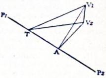
Fig. 95.
§ 35. Application to a Pair of Shifting Pieces.—In fig. 95, let P1P2 be the line of connexion of a pair of pieces, each of which has a motion of translation or shifting. Through any point T in that line draw TV1, TV2, respectively parallel to the simultaneous direction of motion of the pieces; through any other point A in the line of connexion draw a plane perpendicular to that line, cutting TV1, TV2 in V1, V2; then, velocity of piece 1 : velocity of piece 2 :: TV1 : TV2. Also TA represents the equal components of the velocities of the pieces parallel to their line of connexion, and the line V1V2 represents their velocity relatively to each other.
§ 36. Application to a Pair of Turning Pieces.—Let α1, α2 be the angular velocities of a pair of turning pieces; θ1, θ2 the angles which their line of connexion makes with their respective planes of rotation; r1, r2 the common perpendiculars let fall from the line of connexion upon the respective axes of rotation of the pieces. Then the equal components, along the line of connexion, of the velocities of the points where those perpendiculars meet that line are—
α1r1 cos θ1 = α2r2 cos θ2;
consequently, the comparative motion of the pieces is given by the equation
α2 = r1 cos θ1 .
α1 r2 cos θ2
(15)
§ 37. Application to a Shifting Piece and a Turning Piece.—Let a shifting piece be connected with a turning piece, and at a given instant let α1 be the angular velocity of the turning piece, r1 the common perpendicular of its axis of rotation and the line of connexion, θ1 the angle made by the line of connexion with the plane of rotation, θ2 the angle made by the line of connexion with the direction of motion of the shifting piece, v2 the linear velocity of that piece. Then
α1r1 cos θ1 = v2 cos θ2;
(16)
which equation expresses the comparative motion of the two pieces.
§ 38. Classification of Elementary Combinations in Mechanism.—The first systematic classification of elementary combinations in mechanism was that founded by Monge, and fully developed by Lanz and Bétancourt, which has been generally received, and has been adopted in most treatises on applied mechanics. But that classification is founded on the absolute instead of the comparative motions of the pieces, and is, for that reason, defective, as Willis pointed out in his admirable treatise On the Principles of Mechanism.
Willis’s classification is founded, in the first place, on comparative motion, as expressed by velocity ratio and directional relation, and in the second place, on the mode of connexion of the driver and follower. He divides the elementary combinations in mechanism into three classes, of which the characters are as follows:—
Class A: Directional relation constant; velocity ratio constant.
Class B: Directional relation constant; velocity ratio varying.
Class C: Directional relation changing periodically; velocity ratio constant or varying.
Each of those classes is subdivided by Willis into five divisions, of which the characters are as follows:—
Division A: Connexion by rolling contact.
” B: ” ” sliding contact.
” C: ” ” wrapping connectors.
” D: ” ” link-work.
” E: ” ” reduplication.
In the Reuleaux system of analysis of mechanisms the principle of comparative motion is generalized, and mechanisms apparently very diverse in character are shown to be founded on the same sequence of elementary combinations forming a kinematic chain. A short description of this system is given in § 80, but in the present article the principle of Willis’s classification is followed mainly. The arrangement is, however, modified by taking the mode of connexion as the basis of the primary classification, and by removing the subject of connexion by reduplication to the section of aggregate combinations. This modified arrangement is adopted as being better suited than the original arrangement to the limits of an article in an encyclopaedia; but it is not disputed that the original arrangement may be the best for a separate treatise.
§ 39. Rolling Contact: Smooth Wheels and Racks.—In order that two pieces may move in rolling contact, it is necessary that each pair of points in the two pieces which touch each other should at the instant of contact be moving in the same direction with the same velocity. In the case of two shifting pieces this would involve equal and parallel velocities for all the points of each piece, so that there could be no rolling, and, in fact, the two pieces would move like one; hence, in the case of rolling contact, either one or both of the pieces must rotate.
The direction of motion of a point in a turning piece being perpendicular to a plane passing through its axis, the condition that each pair of points in contact with each other must move in the same direction leads to the following consequences:—
I. That, when both pieces rotate, their axes, and all their points of contact, lie in the same plane.
II. That, when one piece rotates, and the other shifts, the axis of the rotating piece, and all the points of contact, lie in a plane perpendicular to the direction of motion of the shifting piece.
The condition that the velocity of each pair of points of contact must be equal leads to the following consequences:—
III. That the angular velocities of a pair of turning pieces in rolling contact must be inversely as the perpendicular distances of any pair of points of contact from the respective axes.
IV. That the linear velocity of a shifting piece in rolling contact with a turning piece is equal to the product of the angular velocity of the turning piece by the perpendicular distance from its axis to a pair of points of contact.
The line of contact is that line in which the points of contact are all situated. Respecting this line, the above Principles III. and IV. lead to the following conclusions:—
V. That for a pair of turning pieces with parallel axes, and for a turning piece and a shifting piece, the line of contact is straight, and parallel to the axes or axis; and hence that the rolling surfaces are either plane or cylindrical (the term “cylindrical” including all surfaces generated by the motion of a straight line parallel to itself).
VI. That for a pair of turning pieces with intersecting axes the line of contact is also straight, and traverses the point of intersection of the axes; and hence that the rolling surfaces are conical, with a common apex (the term “conical” including all surfaces generated by the motion of a straight line which traverses a fixed point).
Turning pieces in rolling contact are called smooth or toothless wheels. Shifting pieces in rolling contact with turning pieces may be called smooth or toothless racks.
VII. In a pair of pieces in rolling contact every straight line traversing the line of contact is a line of connexion.
§ 40. Cylindrical Wheels and Smooth Racks.—In designing cylindrical wheels and smooth racks, and determining their comparative motion, it is sufficient to consider a section of the pair of pieces made by a plane perpendicular to the axis or axes.
The points where axes intersect the plane of section are called centres; the point where the line of contact intersects it, the point of contact, or pitch-point; and the wheels are described as circular, elliptical, &c., according to the forms of their sections made by that plane.
When the point of contact of two wheels lies between their centres, they are said to be in outside gearing; when beyond their centres, in inside gearing, because the rolling surface of the larger wheel must in this case be turned inward or towards its centre.
From Principle III. of § 39 it appears that the angular velocity-ratio of a pair of wheels is the inverse ratio of the distances of the point of contact from the centres respectively.
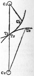
Fig. 96.
For outside gearing that ratio is negative, because the wheels turn contrary ways; for inside gearing it is positive, because they turn the same way.
If the velocity ratio is to be constant, as in Willis’s Class A, the wheels must be circular; and this is the most common form for wheels.
If the velocity ratio is to be variable, as in Willis’s Class B, the figures of the wheels are a pair of rolling curves, subject to the condition that the distance between their poles (which are the centres of rotation) shall be constant.
The following is the geometrical relation which must exist between such a pair of curves:—
Let C1, C2 (fig. 96) be the poles of a pair of rolling curves; T1, T2 any pair of points of contact; U1, U2 any other pair of points of contact. Then, for every possible pair of points of contact, the two following equations must be simultaneously fulfilled:—
Sum of radii, C1U1 + C2U2 = C1T1 + C2T2 = constant; arc, T2U2 = T1U1.
(17)
A condition equivalent to the above, and necessarily connected with it, is, that at each pair of points of contact the inclinations of the curves to their radii-vectores shall be equal and contrary; or, denoting by r1, r2 the radii-vectores at any given pair of points of contact, and s the length of the equal arcs measured from a certain fixed pair of points of contact—
dr2/ds = −dr1/ds;
(18)
which is the differential equation of a pair of rolling curves whose poles are at a constant distance apart.
For full details as to rolling curves, see Willis’s work, already mentioned, and Clerk Maxwell’s paper on Rolling Curves, Trans. Roy. Soc. Edin., 1849.
A rack, to work with a circular wheel, must be straight. To work with a wheel of any other figure, its section must be a rolling curve, subject to the condition that the perpendicular distance from the pole or centre of the wheel to a straight line parallel to the direction of the motion of the rack shall be constant. Let r1 be the radius-vector of a point of contact on the wheel, x2 the ordinate from the straight line before mentioned to the corresponding point of contact on the rack. Then
dx2/ds = −dr1/ds
(19)
is the differential equation of the pair of rolling curves.
To illustrate this subject, it may be mentioned that an ellipse rotating about one focus rolls completely round in outside gearing with an equal and similar ellipse also rotating about one focus, the distance between the axes of rotation being equal to the major axis of the ellipses, and the velocity ratio varying from (1 + eccentricity)/(1 − eccentricity) to (1 − eccentricity)/(1 + eccentricity); an hyperbola rotating about its further focus rolls in inside gearing, through a limited arc, with an equal and similar hyperbola rotating about its nearer focus, the distance between the axes of rotation being equal to the axis of the hyperbolas, and the velocity ratio varying between (eccentricity + 1)/(eccentricity − 1) and unity; and a parabola rotating about its focus rolls with an equal and similar parabola, shifting parallel to its directrix.
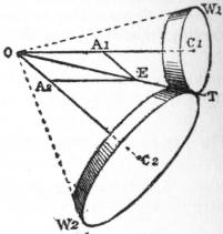
Fig. 97.
§ 41. Conical or Bevel and Disk Wheels.—From Principles III. and VI. of § 39 it appears that the angular velocities of a pair of wheels whose axes meet in a point are to each other inversely as the sines of the angles which the axes of the wheels make with the line of contact. Hence we have the following construction (figs. 97 and 98).—Let O be the apex or point of intersection of the two axes OC1, OC2. The angular velocity ratio being given, it is required to find the line of contact. On OC1, OC2 take lengths OA1, OA2, respectively proportional to the angular velocities of the pieces on whose axes they are taken. Complete the parallelogram OA1EA2; the diagonal OET will be the line of contact required.
When the velocity ratio is variable, the line of contact will shift its position in the plane C1OC2, and the wheels will be cones, with eccentric or irregular bases. In every case which occurs in practice, however, the velocity ratio is constant; the line of contact is constant in position, and the rolling surfaces of the wheels are regular circular cones (when they are called bevel wheels); or one of a pair of wheels may have a flat disk for its rolling surface, as W2 in fig. 98, in which case it is a disk wheel. The rolling surfaces of actual wheels consist of frusta or zones of the complete cones or disks, as shown by W1, W2 in figs. 97 and 98.
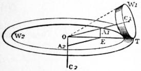
Fig. 98.
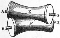
Fig. 99.
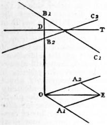
Fig. 100.
§ 42. Sliding Contact (lateral): Skew-Bevel Wheels.—An hyperboloid of revolution is a surface resembling a sheaf or a dice box, generated by the rotation of a straight line round an axis from which it is at a constant distance, and to which it is inclined at a constant angle. If two such hyperboloids E, F, equal or unequal, be placed in the closest possible contact, as in fig. 99, they will touch each other along one of the generating straight lines of each, which will form their line of contact, and will be inclined to the axes AG, BH in opposite directions. The axes will not be parallel, nor will they intersect each other.
The motion of two such hyperboloids, turning in contact with each other, has hitherto been classed amongst cases of rolling contact; but that classification is not strictly correct, for, although the component velocities of a pair of points of contact in a direction at right angles to the line of contact are equal, still, as the axes are parallel neither to each other nor to the line of contact, the velocities of a pair of points of contact have components along the line of contact which are unequal, and their difference constitutes a lateral sliding.
The directions and positions of the axes being given, and the required angular velocity ratio, the following construction serves to determine the line of contact, by whose rotation round the two axes respectively the hyperboloids are generated:—
In fig. 100, let B1C1, B2C2 be the two axes; B1B2 their common perpendicular. Through any point O in this common perpendicular draw OA1 parallel to B1C1 and OA2 parallel to B2C2; make those lines proportional to the angular velocities about the axes to which they are respectively parallel; complete the parallelogram OA1EA2, and draw the diagonal OE; divide B1B2 in D into two parts, inversely proportional to the angular velocities about the axes which they respectively adjoin; through D parallel to OE draw DT. This will be the line of contact.
A pair of thin frusta of a pair of hyperboloids are used in practice to communicate motion between a pair of axes neither parallel nor intersecting, and are called skew-bevel wheels.
In skew-bevel wheels the properties of a line of connexion are not possessed by every line traversing the line of contact, but only by every line traversing the line of contact at right angles.
If the velocity ratio to be communicated were variable, the point D would alter its position, and the line DT its direction, at different periods of the motion, and the wheels would be hyperboloids of an eccentric or irregular cross-section; but forms of this kind are not used in practice.
§ 43. Sliding Contact (circular): Grooved Wheels.—As the adhesion or friction between a pair of smooth wheels is seldom sufficient to prevent their slipping on each other, contrivances are used to increase their mutual hold. One of those consists in forming the rim of each wheel into a series of alternate ridges and grooves parallel to the plane of rotation; it is applicable to cylindrical and bevel wheels, but not to skew-bevel wheels. The comparative motion of a pair of wheels so ridged and grooved is the same as that of a pair of smooth wheels in rolling contact, whose cylindrical or conical surfaces lie midway between the tops of the ridges and bottoms of the grooves, and those ideal smooth surfaces are called the pitch surfaces of the wheels.
The relative motion of the faces of contact of the ridges and grooves is a rotatory sliding or grinding motion, about the line of contact of the pitch-surfaces as an instantaneous axis.
Grooved wheels have hitherto been but little used.
§ 44. Sliding Contact (direct): Teeth of Wheels, their Number and Pitch.—The ordinary method of connecting a pair of wheels, or a wheel and a rack, and the only method which ensures the exact maintenance of a given numerical velocity ratio, is by means of a series of alternate ridges and hollows parallel or nearly parallel to the successive lines of contact of the ideal smooth wheels whose velocity ratio would be the same with that of the toothed wheels. The ridges are called teeth; the hollows, spaces. The teeth of the driver push those of the follower before them, and in so doing sliding takes place between them in a direction across their lines of contact.
The pitch-surfaces of a pair of toothed wheels are the ideal smooth surfaces which would have the same comparative motion by rolling contact that the actual wheels have by the sliding contact of their teeth. The pitch-circles of a pair of circular toothed wheels are sections of their pitch-surfaces, made for spur-wheels (that is, for wheels whose axes are parallel) by a plane at right angles to the axes, and for bevel wheels by a sphere described about the common apex. For a pair of skew-bevel wheels the pitch-circles are a pair of contiguous rectangular sections of the pitch-surfaces. The pitch-point is the point of contact of the pitch-circles.
The pitch-surface of a wheel lies intermediate between the points of the teeth and the bottoms of the hollows between them. That part of the acting surface of a tooth which projects beyond the pitch-surface is called the face; that part which lies within the pitch-surface, the flank.
Teeth, when not otherwise specified, are understood to be made in one piece with the wheel, the material being generally cast-iron, brass or bronze. Separate teeth, fixed into mortises in the rim of the wheel, are called cogs. A pinion is a small toothed wheel; a trundle is a pinion with cylindrical staves for teeth.
The radius of the pitch-circle of a wheel is called the geometrical radius; a circle touching the ends of the teeth is called the addendum circle, and its radius the real radius; the difference between these radii, being the projection of the teeth beyond the pitch-surface, is called the addendum.
The distance, measured along the pitch-circle, from the face of one tooth to the face of the next, is called the pitch. The pitch and the number of teeth in wheels are regulated by the following principles:—
I. In wheels which rotate continuously for one revolution or more, it is obviously necessary that the pitch should be an aliquot part of the circumference.
In wheels which reciprocate without performing a complete revolution this condition is not necessary. Such wheels are called sectors.
II. In order that a pair of wheels, or a wheel and a rack, may work correctly together, it is in all cases essential that the pitch should be the same in each.
III. Hence, in any pair of circular wheels which work together, the numbers of teeth in a complete circumference are directly as the radii and inversely as the angular velocities.
IV. Hence also, in any pair of circular wheels which rotate continuously for one revolution or more, the ratio of the numbers of teeth and its reciprocal the angular velocity ratio must be expressible in whole numbers.
From this principle arise problems of a kind which will be referred to in treating of Trains of Mechanism.
V. Let n, N be the respective numbers of teeth in a pair of wheels, N being the greater. Let t, T be a pair of teeth in the smaller and larger wheel respectively, which at a particular instant work together. It is required to find, first, how many pairs of teeth must pass the line of contact of the pitch-surfaces before t and T work together again (let this number be called a); and, secondly, with how many different teeth of the larger wheel the tooth t will work at different times (let this number be called b); thirdly, with how many different teeth of the smaller wheel the tooth T will work at different times (let this be called c).
Case 1. If n is a divisor of N,
a = N; b = N/n; c = 1.
(20)
Case 2. If the greatest common divisor of N and n be d, a number less than n, so that n = md, N = Md; then
a = mN = Mn = Mmd; b = M; c = m.
(21)
Case 3. If N and n be prime to each other,
a = nN; b = N; c = n.
(22)
It is considered desirable by millwrights, with a view to the preservation of the uniformity of shape of the teeth of a pair of wheels, that each given tooth in one wheel should work with as many different teeth in the other wheel as possible. They therefore study that the numbers of teeth in each pair of wheels which work together shall either be prime to each other, or shall have their greatest common divisor as small as is consistent with a velocity ratio suited for the purposes of the machine.
§ 45. Sliding Contact: Forms of the Teeth of Spur-wheels and Racks.—A line of connexion of two pieces in sliding contact is a line perpendicular to their surfaces at a point where they touch. Bearing this in mind, the principle of the comparative motion of a pair of teeth belonging to a pair of spur-wheels, or to a spur-wheel and a rack, is found by applying the principles stated generally in §§ 36 and 37 to the case of parallel axes for a pair of spur-wheels, and to the case of an axis perpendicular to the direction of shifting for a wheel and a rack.
In fig. 101, let C1, C2 be the centres of a pair of spur-wheels; B1IB1′, B2IB2′ portions of their pitch-circles, touching at I, the pitch-point. Let the wheel 1 be the driver, and the wheel 2 the follower.
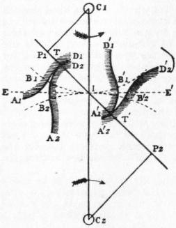
Fig. 101.
Let D1TB1A1, D2TB2A2 be the positions, at a given instant, of the acting surfaces of a pair of teeth in the driver and follower respectively, touching each other at T; the line of connexion of those teeth is P1P2, perpendicular to their surfaces at T. Let C1P1, C2P2 be perpendiculars let fall from the centres of the wheels on the line of contact. Then, by § 36, the angular velocity-ratio is
α2/α1 = C1P1/C2P2.
(23)
The following principles regulate the forms of the teeth and their relative motions:—
I. The angular velocity ratio due to the sliding contact of the teeth will be the same with that due to the rolling contact of the pitch-circles, if the line of connexion of the teeth cuts the line of centres at the pitch-point.
For, let P1P2 cut the line of centres at I; then, by similar triangles,
α1 : α2 :: C2P2 : C1P1 :: IC2 :: IC1;
(24)
which is also the angular velocity ratio due to the rolling contact of the circles B1IB1′, B2IB2′.
This principle determines the forms of all teeth of spur-wheels. It also determines the forms of the teeth of straight racks, if one of the centres be removed, and a straight line EIE′, parallel to the direction of motion of the rack, and perpendicular to C1IC2, be substituted for a pitch-circle.
II. The component of the velocity of the point of contact of the teeth T along the line of connexion is
α1 · C1P1 = α2 · C2P2.
(25)
III. The relative velocity perpendicular to P1P2 of the teeth at their point of contact—that is, their velocity of sliding on each other—is found by supposing one of the wheels, such as 1, to be fixed, the line of centres C1C2 to rotate backwards round C1 with the angular velocity α1, and the wheel 2 to rotate round C2 as before, with the angular velocity α2 relatively to the line of centres C1C2, so as to have the same motion as if its pitch-circle rolled on the pitch-circle of the first wheel. Thus the relative motion of the wheels is unchanged; but 1 is considered as fixed, and 2 has the total motion, that is, a rotation about the instantaneous axis I, with the angular velocity α1 + α2. Hence the velocity of sliding is that due to this rotation about I, with the radius IT; that is to say, its value is
(α1 + α2) · IT;
(26)
so that it is greater the farther the point of contact is from the line of centres; and at the instant when that point passes the line of centres, and coincides with the pitch-point, the velocity of sliding is null, and the action of the teeth is, for the instant, that of rolling contact.
IV. The path of contact is the line traversing the various positions of the point T. If the line of connexion preserves always the same position, the path of contact coincides with it, and is straight; in other cases the path of contact is curved.
It is divided by the pitch-point I into two parts—the arc or line of approach described by T in approaching the line of centres, and the arc or line of recess described by T after having passed the line of centres.
During the approach, the flank D1B1 of the driving tooth drives the face D2B2 of the following tooth, and the teeth are sliding towards each other. During the recess (in which the position of the teeth is exemplified in the figure by curves marked with accented letters), the face B1′A1′ of the driving tooth drives the flank B2′A2′ of the following tooth, and the teeth are sliding from each other.
The path of contact is bounded where the approach commences by the addendum-circle of the follower, and where the recess terminates by the addendum-circle of the driver. The length of the path of contact should be such that there shall always be at least one pair of teeth in contact; and it is better still to make it so long that there shall always be at least two pairs of teeth in contact.
V. The obliquity of the action of the teeth is the angle EIT = IC1, P1 = IC2P2.
In practice it is found desirable that the mean value of the obliquity of action during the contact of teeth should not exceed 15°, nor the maximum value 30°.
It is unnecessary to give separate figures and demonstrations for inside gearing. The only modification required in the formulae is, that in equation (26) the difference of the angular velocities should be substituted for their sum.
§ 46. Involute Teeth.—The simplest form of tooth which fulfils the conditions of § 45 is obtained in the following manner (see fig. 102). Let C1, C2 be the centres of two wheels, B1IB1′, B2IB2′ their pitch-circles, I the pitch-point; let the obliquity of action of the teeth be constant, so that the same straight line P1IP2 shall represent at once the constant line of connexion of teeth and the path of contact. Draw C1P1, C2P2 perpendicular to P1IP2, and with those lines as radii describe about the centres of the wheels the circles D1D1′, D2D2′, called base-circles. It is evident that the radii of the base-circles bear to each other the same proportions as the radii of the pitch-circles, and also that
C1P1 = IC1 · cos obliquity C2P2 = IC2 · cos obliquity.
(27)
(The obliquity which is found to answer best in practice is about 141⁄2°; its cosine is about 31/22, and its sine about 1⁄4. These values though not absolutely exact, are near enough to the truth for practical purposes.)
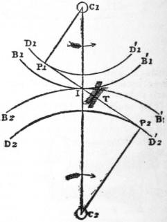
Fig. 102.
Suppose the base-circles to be a pair of circular pulleys connected by means of a cord whose course from pulley to pulley is P1IP2. As the line of connexion of those pulleys is the same as that of the proposed teeth, they will rotate with the required velocity ratio. Now, suppose a tracing point T to be fixed to the cord, so as to be carried along the path of contact P1IP2, that point will trace on a plane rotating along with the wheel 1 part of the involute of the base-circle D1D1′, and on a plane rotating along with the wheel 2 part of the involute of the base-circle D2D2′; and the two curves so traced will always touch each other in the required point of contact T, and will therefore fulfil the condition required by Principle I. of § 45.
Consequently, one of the forms suitable for the teeth of wheels is the involute of a circle; and the obliquity of the action of such teeth is the angle whose cosine is the ratio of the radius of their base-circle to that of the pitch-circle of the wheel.
All involute teeth of the same pitch work smoothly together.
To find the length of the path of contact on either side of the pitch-point I, it is to be observed that the distance between the fronts of two successive teeth, as measured along P1IP2, is less than the pitch in the ratio of cos obliquity : I; and consequently that, if distances equal to the pitch be marked off either way from I towards P1 and P2 respectively, as the extremities of the path of contact, and if, according to Principle IV. of § 45, the addendum-circles be described through the points so found, there will always be at least two pairs of teeth in action at once. In practice it is usual to make the path of contact somewhat longer, viz. about 2.4 times the pitch; and with this length of path, and the obliquity already mentioned of 141⁄2°, the addendum is about 3.1 of the pitch.
The teeth of a rack, to work correctly with wheels having involute teeth, should have plane surfaces perpendicular to the line of connexion, and consequently making with the direction of motion of the rack angles equal to the complement of the obliquity of action.
§ 47. Teeth for a given Path of Contact: Sang’s Method.—In the preceding section the form of the teeth is found by assuming a figure for the path of contact, viz. the straight line. Any other convenient figure may be assumed for the path of contact, and the corresponding forms of the teeth found by determining what curves a point T, moving along the assumed path of contact, will trace on two disks rotating round the centres of the wheels with angular velocities bearing that relation to the component velocity of T along TI, which is given by Principle II. of § 45, and by equation (25). This method of finding the forms of the teeth of wheels forms the subject of an elaborate and most interesting treatise by Edward Sang.
All wheels having teeth of the same pitch, traced from the same path of contact, work correctly together, and are said to belong to the same set.
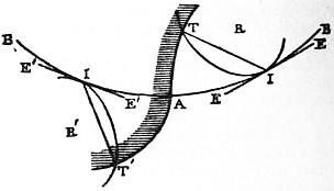
Fig. 103.
§ 48. Teeth traced by Rolling Curves.—If any curve R (fig. 103) be rolled on the inside of the pitch-circle BB of a wheel, it appears, from § 30, that the instantaneous axis of the rolling curve at any instant will be at the point I, where it touches the pitch-circle for the moment, and that consequently the line AT, traced by a tracing-point T, fixed to the rolling curve upon the plane of the wheel, will be everywhere perpendicular to the straight line TI; so that the traced curve AT will be suitable for the flank of a tooth, in which T is the point of contact corresponding to the position I of the pitch-point. If the same rolling curve R, with the same tracing-point T, be rolled on the outside of any other pitch-circle, it will have the face of a tooth suitable to work with the flank AT.
In like manner, if either the same or any other rolling curve R′ be rolled the opposite way, on the outside of the pitch-circle BB, so that the tracing point T′ shall start from A, it will trace the face AT′ of a tooth suitable to work with a flank traced by rolling the same curve R′ with the same tracing-point T′ inside any other pitch-circle.
The figure of the path of contact is that traced on a fixed plane by the tracing-point, when the rolling curve is rotated in such a manner as always to touch a fixed straight line EIE (or E′I′E′, as the case may be) at a fixed point I (or I′).
If the same rolling curve and tracing-point be used to trace both the faces and the flanks of the teeth of a number of wheels of different sizes but of the same pitch, all those wheels will work correctly together, and will form a set. The teeth of a rack, of the same set, are traced by rolling the rolling curve on both sides of a straight line.
The teeth of wheels of any figure, as well as of circular wheels, may be traced by rolling curves on their pitch-surfaces; and all teeth of the same pitch, traced by the same rolling curve with the same tracing-point, will work together correctly if their pitch-surfaces are in rolling contact.
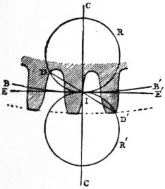
Fig. 104.
§ 49. Epicycloidal Teeth.—The most convenient rolling curve is the circle. The path of contact which it traces is identical with itself; and the flanks of the teeth are internal and their faces external epicycloids for wheels, and both flanks and faces are cycloids for a rack.
For a pitch-circle of twice the radius of the rolling or describing circle (as it is called) the internal epicycloid is a straight line, being, in fact, a diameter of the pitch-circle, so that the flanks of the teeth for such a pitch-circle are planes radiating from the axis. For a smaller pitch-circle the flanks would be convex and in-curved or under-cut, which would be inconvenient; therefore the smallest wheel of a set should have its pitch-circle of twice the radius of the describing circle, so that the flanks may be either straight or concave.
In fig. 104 let BB′ be part of the pitch-circle of a wheel with epicycloidal teeth; CIC′ the line of centres; I the pitch-point; EIE′ a straight tangent to the pitch-circle at that point; R the internal and R′ the equal external describing circles, so placed as to touch the pitch-circle and each other at I. Let DID′ be the path of contact, consisting of the arc of approach DI and the arc of recess ID′. In order that there may always be at least two pairs of teeth in action, each of those arcs should be equal to the pitch.
The obliquity of the action in passing the line of centres is nothing; the maximum obliquity is the angle EID = E′ID; and the mean obliquity is one-half of that angle.
It appears from experience that the mean obliquity should not exceed 15°; therefore the maximum obliquity should be about 30°; therefore the equal arcs DI and ID′ should each be one-sixth of a circumference; therefore the circumference of the describing circle should be six times the pitch.
It follows that the smallest pinion of a set in which pinion the flanks are straight should have twelve teeth.
§ 50. Nearly Epicycloidal Teeth: Willis’s Method.—To facilitate the drawing of epicycloidal teeth in practice, Willis showed how to approximate to their figure by means of two circular arcs—one concave, for the flank, and the other convex, for the face—and each having for its radius the mean radius of curvature of the epicycloidal arc. Willis’s formulae are founded on the following properties of epicycloids:—
Let R be the radius of the pitch-circle; r that of the describing circle; θ the angle made by the normal TI to the epicycloid at a given point T, with a tangent to the circle at I—that is, the obliquity of the action at T.
Then the radius of curvature of the epicycloid at T is—
For an internal epicycloid, ρ = 4r sin θ R − r
R − 2r
For an external epicycloid, ρ′ = 4r sin θ R + r
R + 2r
(28)
Also, to find the position of the centres of curvature relatively to the pitch-circle, we have, denoting the chord of the describing circle TI by c, c = 2r sin θ; and therefore
For the flank, ρ − c = 2r sin θ R
R − 2r
For the face, ρ′ − c = 2r sin θ R
R + 2r
(29)
For the proportions approved of by Willis, sin θ = 1⁄4 nearly; r = p (the pitch) nearly; c = 1⁄2p nearly; and, if N be the number of teeth in the wheel, r/R = 6/N nearly; therefore, approximately,
ρ − c = p · N
2 N − 12
ρ − c = p · N
2 N + 12
(30)
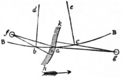
Fig. 105.
Hence the following construction (fig. 105). Let BB be part of the pitch-circle, and a the point where a tooth is to cross it. Set off ab = ac − 1⁄2p. Draw radii bd, ce; draw fb, cg, making angles of 751⁄2° with those radii. Make bf = p′ − c, cg = p − c. From f, with the radius fa, draw the circular arc ah; from g, with the radius ga, draw the circular arc ak. Then ah is the face and ak the flank of the tooth required.
To facilitate the application of this rule, Willis published tables of ρ − c and ρ′ − c, and invented an instrument called the “odontograph.”
§ 51. Trundles and Pin-Wheels.—If a wheel or trundle have cylindrical pins or staves for teeth, the faces of the teeth of a wheel suitable for driving it are described by first tracing external epicycloids, by rolling the pitch-circle of the pin-wheel or trundle on the pitch-circle of the driving-wheel, with the centre of a stave for a tracing-point, and then drawing curves parallel to, and within the epicycloids, at a distance from them equal to the radius of a stave. Trundles having only six staves will work with large wheels.
§ 52. Backs of Teeth and Spaces.—Toothed wheels being in general intended to rotate either way, the backs of the teeth are made similar to the fronts. The space between two teeth, measured on the pitch-circle, is made about 1⁄6th part wider than the thickness of the tooth on the pitch-circle—that is to say,
Thickness of tooth = 5⁄11 pitch;
Width of space = 6⁄11 pitch.
The difference of 1⁄11 of the pitch is called the back-lash. The clearance allowed between the points of teeth and the bottoms of the spaces between the teeth of the other wheel is about one-tenth of the pitch.
§ 53. Stepped and Helical Teeth.—R. J. Hooke invented the making of the fronts of teeth in a series of steps with a view to increase the smoothness of action. A wheel thus formed resembles in shape a series of equal and similar toothed disks placed side by side, with the teeth of each a little behind those of the preceding disk. He also invented, with the same object, teeth whose fronts, instead of being parallel to the line of contact of the pitch-circles, cross it obliquely, so as to be of a screw-like or helical form. In wheel-work of this kind the contact of each pair of teeth commences at the foremost end of the helical front, and terminates at the aftermost end; and the helix is of such a pitch that the contact of one pair of teeth shall not terminate until that of the next pair has commenced.
Stepped and helical teeth have the desired effect of increasing the smoothness of motion, but they require more difficult and expensive workmanship than common teeth; and helical teeth are, besides, open to the objection that they exert a laterally oblique pressure, which tends to increase resistance, and unduly strain the machinery.
§ 54. Teeth of Bevel-Wheels.—The acting surfaces of the teeth of bevel-wheels are of the conical kind, generated by the motion of a line passing through the common apex of the pitch-cones, while its extremity is carried round the outlines of the cross section of the teeth made by a sphere described about that apex.
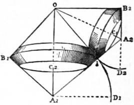
Fig. 106.
The operations of describing the exact figures of the teeth of bevel-wheels, whether by involutes or by rolling curves, are in every respect analogous to those for describing the figures of the teeth of spur-wheels, except that in the case of bevel-wheels all those operations are to be performed on the surface of a sphere described about the apex instead of on a plane, substituting poles for centres, and great circles for straight lines.
In consideration of the practical difficulty, especially in the case of large wheels, of obtaining an accurate spherical surface, and of drawing upon it when obtained, the following approximate method, proposed originally by Tredgold, is generally used:—
Let O (fig. 106) be the common apex of a pair of bevel-wheels; OB1I, OB2I their pitch cones; OC1, OC2 their axes; OI their line of contact. Perpendicular to OI draw A1IA2, cutting the axes in A1, A2; make the outer rims of the patterns and of the wheels portions of the cones A1B1I, A2B2I, of which the narrow zones occupied by the teeth will be sufficiently near to a spherical surface described about O for practical purposes. To find the figures of the teeth, draw on a flat surface circular arcs ID1, ID2, with the radii A1I, A2I; those arcs will be the developments of arcs of the pitch-circles B1I, B2I, when the conical surfaces A1B1I, A2B2I are spread out flat. Describe the figures of teeth for the developed arcs as for a pair of spur-wheels; then wrap the developed arcs on the cones, so as to make them coincide with the pitch-circles, and trace the teeth on the conical surfaces.
§ 55. Teeth of Skew-Bevel Wheels.—The crests of the teeth of a skew-bevel wheel are parallel to the generating straight line of the hyperboloidal pitch-surface; and the transverse sections of the teeth at a given pitch-circle are similar to those of the teeth of a bevel-wheel whose pitch surface is a cone touching the hyperboloidal surface at the given circle.
§ 56. Cams.—A cam is a single tooth, either rotating continuously or oscillating, and driving a sliding or turning piece either constantly or at intervals. All the principles which have been stated in § 45 as being applicable to teeth are applicable to cams; but in designing cams it is not usual to determine or take into consideration the form of the ideal pitch-surface, which would give the same comparative motion by rolling contact that the cam gives by sliding contact.
§ 57. Screws.—The figure of a screw is that of a convex or concave cylinder, with one or more helical projections, called threads, winding round it. Convex and concave screws are distinguished technically by the respective names of male and female; a short concave screw is called a nut; and when a screw is spoken of without qualification a convex screw is usually understood.
The relation between the advance and the rotation, which compose the motion of a screw working in contact with a fixed screw or helical guide, has already been demonstrated in § 32; and the same relation exists between the magnitudes of the rotation of a screw about a fixed axis and the advance of a shifting nut in which it rotates. The advance of the nut takes place in the opposite direction to that of the advance of the screw in the case in which the nut is fixed. The pitch or axial pitch of a screw has the meaning assigned to it in that section, viz. the distance, measured parallel to the axis, between the corresponding points in two successive turns of the same thread. If, therefore, the screw has several equidistant threads, the true pitch is equal to the divided axial pitch, as measured between two adjacent threads, multiplied by the number of threads.
If a helix be described round the screw, crossing each turn of the thread at right angles, the distance between two corresponding points on two successive turns of the same thread, measured along this normal helix, may be called the normal pitch; and when the screw has more than one thread the normal pitch from thread to thread may be called the normal divided pitch.
The distance from thread to thread, measured on a circle described about the axis of the screw, called the pitch-circle, may be called the circumferential pitch; for a screw of one thread it is one circumference; for a screw of n threads, (one circumference)/n.
Let r denote the radius of the pitch circle;
n the number of threads;
θ the obliquity of the threads to the pitch circle, and of the normal helix to the axis;
Pa the axial pitch
Pa/n = pa divided pitch;
Pn the normal pitch
Pn/n = pn divided pitch;
Pc the circumferential pitch;
then
pc = pa cot θ = pn cos θ = 2πr ,
n
pa = pn sec θ = pc tan θ = 2πr tan θ ,
n
pn = pc sin θ = pa cos θ = 2πr sin θ .
n
(31)
If a screw rotates, the number of threads which pass a fixed point in one revolution is the number of threads in the screw.
A pair of convex screws, each rotating about its axis, are used as an elementary combination to transmit motion by the sliding contact of their threads. Such screws are commonly called endless screws. At the point of contact of the screws their threads must be parallel; and their line of connexion is the common perpendicular to the acting surfaces of the threads at their point of contact. Hence the following principles:—
I. If the screws are both right-handed or both left-handed, the angle between the directions of their axes is the sum of their obliquities; if one is right-handed and the other left-handed, that angle is the difference of their obliquities.
II. The normal pitch for a screw of one thread, and the normal divided pitch for a screw of more than one thread, must be the same in each screw.
III. The angular velocities of the screws are inversely as their numbers of threads.
Hooke’s wheels with oblique or helical teeth are in fact screws of many threads, and of large diameters as compared with their lengths.
The ordinary position of a pair of endless screws is with their axes at right angles to each other. When one is of considerably greater diameter than the other, the larger is commonly called in practice a wheel, the name screw being applied to the smaller only; but they are nevertheless both screws in fact.
To make the teeth of a pair of endless screws fit correctly and work smoothly, a hardened steel screw is made of the figure of the smaller screw, with its thread or threads notched so as to form a cutting tool; the larger screw, or “wheel,” is cast approximately of the required figure; the larger screw and the steel screw are fitted up in their proper relative position, and made to rotate in contact with each other by turning the steel screw, which cuts the threads of the larger screw to their true figure.
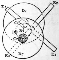
Fig. 107.
§ 58. Coupling of Parallel Axes—Oldham’s Coupling.—A coupling is a mode of connecting a pair of shafts so that they shall rotate in the same direction with the same mean angular velocity. If the axes of the shafts are in the same straight line, the coupling consists in so connecting their contiguous ends that they shall rotate as one piece; but if the axes are not in the same straight line combinations of mechanism are required. A coupling for parallel shafts which acts by sliding contact was invented by Oldham, and is represented in fig. 107. C1, C2 are the axes of the two parallel shafts; D1, D2 two disks facing each other, fixed on the ends of the two shafts respectively; E1E1 a bar sliding in a diametral groove in the face of D1; E2E2 a bar sliding in a diametral groove in the face of D2: those bars are fixed together at A, so as to form a rigid cross. The angular velocities of the two disks and of the cross are all equal at every instant; the middle point of the cross, at A, revolves in the dotted circle described upon the line of centres C1C2 as a diameter twice for each turn of the disks and cross; the instantaneous axis of rotation of the cross at any instant is at I, the point in the circle C1C2 diametrically opposite to A.
Oldham’s coupling may be used with advantage where the axes of the shafts are intended to be as nearly in the same straight line as is possible, but where there is some doubt as to the practibility or permanency of their exact continuity.
§ 59. Wrapping Connectors—Belts, Cords and Chains.—Flat belts of leather or of gutta percha, round cords of catgut, hemp or other material, and metal chains are used as wrapping connectors to transmit rotatory motion between pairs of pulleys and drums.
Belts (the most frequently used of all wrapping connectors) require nearly cylindrical pulleys. A belt tends to move towards that part of a pulley whose radius is greatest; pulleys for belts, therefore, are slightly swelled in the middle, in order that the belt may remain on the pulley, unless forcibly shifted. A belt when in motion is shifted off a pulley, or from one pulley on to another of equal size alongside of it, by pressing against that part of the belt which is moving towards the pulley.
Cords require either cylindrical drums with ledges or grooved pulleys.
Chains require pulleys or drums, grooved, notched and toothed, so as to fit the links of the chain.
Wrapping connectors for communicating continuous motion are endless.
Wrapping connectors for communicating reciprocating motion have usually their ends made fast to the pulleys or drums which they connect, and which in this case may be sectors.
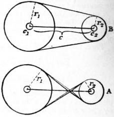
Fig. 108.
The line of connexion of two pieces connected by a wrapping connector is the centre line of the belt, cord or chain; and the comparative motions of the pieces are determined by the principles of § 36 if both pieces turn, and of § 37 if one turns and the other shifts, in which latter case the motion must be reciprocating.
The pitch-line of a pulley or drum is a curve to which the line of connexion is always a tangent—that is to say, it is a curve parallel to the acting surface of the pulley or drum, and distant from it by half the thickness of the wrapping connector.
Pulleys and drums for communicating a constant velocity ratio are circular. The effective radius, or radius of the pitch-circle of a circular pulley or drum, is equal to the real radius added to half the thickness of the connector. The angular velocities of a pair of connected circular pulleys or drums are inversely as the effective radii.
A crossed belt, as in fig. 108, A, reverses the direction of the rotation communicated; an uncrossed belt, as in fig. 108, B, preserves that direction.
The length L of an endless belt connecting a pair of pulleys whose effective radii are r1, r2, with parallel axes whose distance apart is c, is given by the following formulae, in each of which the first term, containing the radical, expresses the length of the straight parts of the belt, and the remainder of the formula the length of the curved parts.
For a crossed belt:—
L = 2 √ {c2 − (r1 + r2)2} + (r1 + r2) ( π − 2 sin−1 r1 + r2 );
c
(32 A)
and for an uncrossed belt:—
L = 2 √ {c2 − (r1 − r2)2 } + π (r1 + r2 + 2 (r1 − r2) sin−1 r1 − r2 ;
c
(32 B)
in which r1 is the greater radius, and r2 the less.
When the axes of a pair of pulleys are not parallel, the pulleys should be so placed that the part of the belt which is approaching each pulley shall be in the plane of the pulley.
§ 60. Speed-Cones.—A pair of speed-cones (fig. 109) is a contrivance for varying and adjusting the velocity ratio communicated between a pair of parallel shafts by means of a belt. The speed-cones are either continuous cones or conoids, as A, B, whose velocity ratio can be varied gradually while they are in motion by shifting the belt, or sets of pulleys whose radii vary by steps, as C, D, in which case the velocity ratio can be changed by shifting the belt from one pair of pulleys to another.
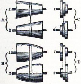
Fig. 109.
In order that the belt may fit accurately in every possible position on a pair of speed-cones, the quantity L must be constant, in equations (32 A) or (32 B), according as the belt is crossed or uncrossed.
For a crossed belt, as in A and C, fig. 109, L depends solely on c and on r1 + r2. Now c is constant because the axes are parallel; therefore the sum of the radii of the pitch-circles connected in every position of the belt is to be constant. That condition is fulfilled by a pair of continuous cones generated by the revolution of two straight lines inclined opposite ways to their respective axes at equal angles.
For an uncrossed belt, the quantity L in equation (32 B) is to be made constant. The exact fulfilment of this condition requires the solution of a transcendental equation; but it may be fulfilled with accuracy sufficient for practical purposes by using, instead of (32 B) the following approximate equation:—
L nearly = 2c + π (r1 + r2) + (r1 − r2)2 / c.
(33)
The following is the most convenient practical rule for the application of this equation:—
Let the speed-cones be equal and similar conoids, as in B, fig. 109, but with their large and small ends turned opposite ways. Let r1 be the radius of the large end of each, r2 that of the small end, r0 that of the middle; and let v be the sagitta, measured perpendicular to the axes, of the arc by whose revolution each of the conoids is generated, or, in other words, the bulging of the conoids in the middle of their length. Then
v = r0 − (r1 + r2) / 2 = (r1 − r2)2 / 2πc.
(34)
2π = 6.2832; but 6 may be used in most practical cases without sensible error.
The radii at the middle and end being thus determined, make the generating curve an arc either of a circle or of a parabola.
§ 61. Linkwork in General.—The pieces which are connected by linkwork, if they rotate or oscillate, are usually called cranks, beams and levers. The link by which they are connected is a rigid rod or bar, which may be straight or of any other figure; the straight figure being the most favourable to strength, is always used when there is no special reason to the contrary. The link is known by various names in various circumstances, such as coupling-rod, connecting-rod, crank-rod, eccentric-rod, &c. It is attached to the pieces which it connects by two pins, about which it is free to turn. The effect of the link is to maintain the distance between the axes of those pins invariable; hence the common perpendicular of the axes of the pins is the line of connexion, and its extremities may be called the connected points. In a turning piece, the perpendicular let fall from its connected point upon its axis of rotation is the arm or crank-arm.
The axes of rotation of a pair of turning pieces connected by a link are almost always parallel, and perpendicular to the line of connexion in which case the angular velocity ratio at any instant is the reciprocal of the ratio of the common perpendiculars let fall from the line of connexion upon the respective axes of rotation.
If at any instant the direction of one of the crank-arms coincides with the line of connexion, the common perpendicular of the line of connexion and the axis of that crank-arm vanishes, and the directional relation of the motions becomes indeterminate. The position of the connected point of the crank-arm in question at such an instant is called a dead-point. The velocity of the other connected point at such an instant is null, unless it also reaches a dead-point at the same instant, so that the line of connexion is in the plane of the two axes of rotation, in which case the velocity ratio is indeterminate. Examples of dead-points, and of the means of preventing the inconvenience which they tend to occasion, will appear in the sequel.
§ 62. Coupling of Parallel Axes.—Two or more parallel shafts (such as those of a locomotive engine, with two or more pairs of driving wheels) are made to rotate with constantly equal angular velocities by having equal cranks, which are maintained parallel by a coupling-rod of such a length that the line of connexion is equal to the distance between the axes. The cranks pass their dead-points simultaneously. To obviate the unsteadiness of motion which this tends to cause, the shafts are provided with a second set of cranks at right angles to the first, connected by means of a similar coupling-rod, so that one set of cranks pass their dead points at the instant when the other set are farthest from theirs.
§ 63. Comparative Motion of Connected Points.—As the link is a rigid body, it is obvious that its action in communicating motion may be determined by finding the comparative motion of the connected points, and this is often the most convenient method of proceeding.
If a connected point belongs to a turning piece, the direction of its motion at a given instant is perpendicular to the plane containing the axis and crank-arm of the piece. If a connected point belongs to a shifting piece, the direction of its motion at any instant is given, and a plane can be drawn perpendicular to that direction.
The line of intersection of the planes perpendicular to the paths of the two connected points at a given instant is the instantaneous axis of the link at that instant; and the velocities of the connected points are directly as their distances from that axis.
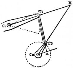
Fig. 110.
In drawing on a plane surface, the two planes perpendicular to the paths of the connected points are represented by two lines (being their sections by a plane normal to them), and the instantaneous axis by a point (fig. 110); and, should the length of the two lines render it impracticable to produce them until they actually intersect, the velocity ratio of the connected points may be found by the principle that it is equal to the ratio of the segments which a line parallel to the line of connexion cuts off from any two lines drawn from a given point, perpendicular respectively to the paths of the connected points.
To illustrate this by one example. Let C1 be the axis, and T1 the connected point of the beam of a steam-engine; T1T2 the connecting or crank-rod; T2 the other connected point, and the centre of the crank-pin; C2 the axis of the crank and its shaft. Let v1 denote the velocity of T1 at any given instant; v2 that of T2. To find the ratio of these velocities, produce C1T1, C2T2 till they intersect in K; K is the instantaneous axis of the connecting rod, and the velocity ratio is
v1 : v2 :: KT1 : KT2.
(35)
Should K be inconveniently far off, draw any triangle with its sides respectively parallel to C1T1, C2T2 and T1T2; the ratio of the two sides first mentioned will be the velocity ratio required. For example, draw C2A parallel to C1T1, cutting T1T2 in A; then
v1 : v2 :: C2A : C2T2.
(36)
§ 64. Eccentric.—An eccentric circular disk fixed on a shaft, and used to give a reciprocating motion to a rod, is in effect a crank-pin of sufficiently large diameter to surround the shaft, and so to avoid the weakening of the shaft which would arise from bending it so as to form an ordinary crank. The centre of the eccentric is its connected point; and its eccentricity, or the distance from that centre to the axis of the shaft, is its crank-arm.
An eccentric may be made capable of having its eccentricity altered by means of an adjusting screw, so as to vary the extent of the reciprocating motion which it communicates.
§ 65. Reciprocating Pieces—Stroke—Dead-Points.—The distance between the extremities of the path of the connected point in a reciprocating piece (such as the piston of a steam-engine) is called the stroke or length of stroke of that piece. When it is connected with a continuously turning piece (such as the crank of a steam-engine) the ends of the stroke of the reciprocating piece correspond to the dead-points of the path of the connected point of the turning piece, where the line of connexion is continuous with or coincides with the crank-arm.
Let S be the length of stroke of the reciprocating piece, L the length of the line of connexion, and R the crank-arm of the continuously turning piece. Then, if the two ends of the stroke be in one straight line with the axis of the crank,
S = 2R;
(37)
and if these ends be not in one straight line with that axis, then S, L − R, and L + R, are the three sides of a triangle, having the angle opposite S at that axis; so that, if θ be the supplement of the arc between the dead-points,
S2 = 2 (L2 + R2) − 2 (L2 − R2) cos θ,
cos θ = 2L2 + 2R2 − S2 .
2 (L2 − R2)
(38)
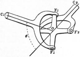
Fig. 111.
§ 66. Coupling of Intersecting Axes—Hooke’s Universal Joint.—Intersecting axes are coupled by a contrivance of Hooke’s, known as the “universal joint,” which belongs to the class of linkwork (see fig. 111). Let O be the point of intersection of the axes OC1, OC2, and θ their angle of inclination to each other. The pair of shafts C1, C2 terminate in a pair of forks F1, F2 in bearings at the extremities of which turn the gudgeons at the ends of the arms of a rectangular cross, having its centre at O. This cross is the link; the connected points are the centres of the bearings F1, F2. At each instant each of those points moves at right angles to the central plane of its shaft and fork, therefore the line of intersection of the central planes of the two forks at any instant is the instantaneous axis of the cross, and the velocity ratio of the points F1, F2 (which, as the forks are equal, is also the angular velocity ratio of the shafts) is equal to the ratio of the distances of those points from that instantaneous axis. The mean value of that velocity ratio is that of equality, for each successive quarter-turn is made by both shafts in the same time; but its actual value fluctuates between the limits:—
α2 = 1 when F1 is the plane of OC1C2
α1 cos θ
and α2 = cos θ when F2 is in that plane.
α1
(39)
Its value at intermediate instants is given by the following equations: let φ1, φ2 be the angles respectively made by the central planes of the forks and shafts with the plane OC1C2 at a given instant; then
cos θ = tan φ1 tan φ2,
α2 = − dφ2 = tan φ1 + cot φ1 .
α1 dφ1 tan φ2 + cot φ2
(40)
§ 67. Intermittent Linkwork—Click and Ratchet.—A click acting upon a ratchet-wheel or rack, which it pushes or pulls through a certain arc at each forward stroke and leaves at rest at each backward stroke, is an example of intermittent linkwork. During the forward stroke the action of the click is governed by the principles of linkwork; during the backward stroke that action ceases. A catch or pall, turning on a fixed axis, prevents the ratchet-wheel or rack from reversing its motion.
Division 5.—Trains of Mechanism.
§ 68. General Principles..—A train of mechanism consists of a series of pieces each of which is follower to that which drives it and driver to that which follows it.
The comparative motion of the first driver and last follower is obtained by combining the proportions expressing by their terms the velocity ratios and by their signs the directional relations of the several elementary combinations of which the train consists.
§ 69. Trains of Wheelwork.—Let A1, A2, A3, &c., Am−1, Am denote a series of axes, and α1, α2, α3, &c., αm−1, αm their angular velocities. Let the axis A1 carry a wheel of N1 teeth, driving a wheel of n2 teeth on the axis A2, which carries also a wheel of N2 teeth, driving a wheel of n3 teeth on the axis A3, and so on; the numbers of teeth in drivers being denoted by N′s, and in followers by n’s, and the axes to which the wheels are fixed being denoted by numbers. Then the resulting velocity ratio is denoted by
αm = α2 · α3 · &c. ... αm = N1 · N2 ... &c. ... Nm−1 ;
α1 α1 α2 αm−1 n2 · n3 ... &c. ... nm
(41)
that is to say, the velocity ratio of the last and first axes is the ratio of the product of the numbers of teeth in the drivers to the product of the numbers of teeth in the followers.
Supposing all the wheels to be in outside gearing, then, as each elementary combination reverses the direction of rotation, and as the number of elementary combinations m − 1 is one less than the number of axes m, it is evident that if m is odd the direction of rotation is preserved, and if even reversed.
It is often a question of importance to determine the number of teeth in a train of wheels best suited for giving a determinate velocity ratio to two axes. It was shown by Young that, to do this with the least total number of teeth, the velocity ratio of each elementary combination should approximate as nearly as possible to 3.59. This would in many cases give too many axes; and, as a useful practical rule, it may be laid down that from 3 to 6 ought to be the limit of the velocity ratio of an elementary combination in wheel-work. The smallest number of teeth in a pinion for epicycloidal teeth ought to be twelve (see § 49)—but it is better, for smoothness of motion, not to go below fifteen; and for involute teeth the smallest number is about twenty-four.
Let B/C be the velocity ratio required, reduced to its least terms, and let B be greater than C. If B/C is not greater than 6, and C lies between the prescribed minimum number of teeth (which may be called t) and its double 2t, then one pair of wheels will answer the purpose, and B and C will themselves be the numbers required. Should B and C be inconveniently large, they are, if possible, to be resolved into factors, and those factors (or if they are too small, multiples of them) used for the number of teeth. Should B or C, or both, be at once inconveniently large and prime, then, instead of the exact ratio B/C some ratio approximating to that ratio, and capable of resolution into convenient factors, is to be found by the method of continued fractions.
Should B/C be greater than 6, the best number of elementary combinations m − 1 will lie between
log B − log C and log B − log C .
log 6 log 3
Then, if possible, B and C themselves are to be resolved each into m − 1 factors (counting 1 as a factor), which factors, or multiples of them, shall be not less than t nor greater than 6t; or if B and C contain inconveniently large prime factors, an approximate velocity ratio, found by the method of continued fractions, is to be substituted for B/C as before.
So far as the resultant velocity ratio is concerned, the order of the drivers N and of the followers n is immaterial: but to secure equable wear of the teeth, as explained in § 44, the wheels ought to be so arranged that, for each elementary combination, the greatest common divisor of N and n shall be either 1, or as small as possible.
§ 70. Double Hooke’s Coupling.—It has been shown in § 66 that the velocity ratio of a pair of shafts coupled by a universal joint fluctuates between the limits cos θ and 1/cos θ. Hence one or both of the shafts must have a vibratory and unsteady motion, injurious to the mechanism and framework. To obviate this evil a short intermediate shaft is introduced, making equal angles with the first and last shaft, coupled with each of them by a Hooke’s joint, and having its own two forks in the same plane. Let α1, α2, α3 be the angular velocities of the first, intermediate, and last shaft in this train of two Hooke’s couplings. Then, from the principles of § 60 it is evident that at each instant α2/α1 = α2/α3, and consequently that α3 = α1; so that the fluctuations of angular velocity ratio caused by the first coupling are exactly neutralized by the second, and the first and last shafts have equal angular velocities at each instant.
§ 71. Converging and Diverging Trains of Mechanism.—Two or more trains of mechanism may converge into one—as when the two pistons of a pair of steam-engines, each through its own connecting-rod, act upon one crank-shaft. One train of mechanism may diverge into two or more—as when a single shaft, driven by a prime mover, carries several pulleys, each of which drives a different machine. The principles of comparative motion in such converging and diverging trains are the same as in simple trains.
Division 6.—Aggregate Combinations.
§ 72. General Principles.—Willis designated as “aggregate combinations” those assemblages of pieces of mechanism in which the motion of one follower is the resultant of component motions impressed on it by more than one driver. Two classes of aggregate combinations may be distinguished which, though not different in their actual nature, differ in the data which they present to the designer, and in the method of solution to be followed in questions respecting them.
Class I. comprises those cases in which a piece A is not carried directly by the frame C, but by another piece B, relatively to which the motion of A is given—the motion of the piece B relatively to the frame C being also given. Then the motion of A relatively to the frame C is the resultant of the motion of A relatively to B and of B relatively to C; and that resultant is to be found by the principles already explained in Division 3 of this Chapter §§ 27-32.
Class II. comprises those cases in which the motions of three points in one follower are determined by their connexions with two or with three different drivers.
This classification is founded on the kinds of problems arising from the combinations. Willis adopts another classification founded on the objects of the combinations, which objects he divides into two classes, viz. (1) to produce aggregate velocity, or a velocity which is the resultant of two or more components in the same path, and (2) to produce an aggregate path—that is, to make a given point in a rigid body move in an assigned path by communicating certain motions to other points in that body.
It is seldom that one of these effects is produced without at the same time producing the other; but the classification of Willis depends upon which of those two effects, even supposing them to occur together, is the practical object of the mechanism.
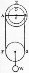
Fig. 112.
§ 73. Differential Windlass.—The axis C (fig. 112) carries a larger barrel AE and a smaller barrel DB, rotating as one piece with the angular velocity α1 in the direction AE. The pulley or sheave FG has a weight W hung to its centre. A cord has one end made fast to and wrapped round the barrel AE; it passes from A under the sheave FG, and has the other end wrapped round and made fast to the barrel BD. Required the relation between the velocity of translation v2 of W and the angular velocity α1 of the differential barrel.
In this case v2 is an aggregate velocity, produced by the joint action of the two drivers AE and BD, transmitted by wrapping connectors to FG, and combined by that sheave so as to act on the follower W, whose motion is the same with that of the centre of FG.
The velocity of the point F is α1·AC, upward motion being considered positive. The velocity of the point G is −α1·CB, downward motion being negative. Hence the instantaneous axis of the sheave FG is in the diameter FG, at the distance
FG · AC − BC
2 AC + BC
from the centre towards G; the angular velocity of the sheave is
α2 = α1 · AC + BC ;
FG
and, consequently, the velocity of its centre is
v2 = α2 · FG · AC − BC = α1 (AC − BC) ,
2 AC + BC 2
(42)
or the mean between the velocities of the two vertical parts of the cord.
If the cord be fixed to the framework at the point B, instead of being wound on a barrel, the velocity of W is half that of AF.
A case containing several sheaves is called a block. A fall-block is attached to a fixed point; a running-block is movable to and from a fall-block, with which it is connected by two or more plies of a rope. The whole combination constitutes a tackle or purchase. (See Pulleys for practical applications of these principles.)
§ 74. Differential Screw.—On the same axis let there be two screws of the respective pitches p1 and p2, made in one piece, and rotating with the angular velocity α. Let this piece be called B. Let the first screw turn in a fixed nut C, and the second in a sliding nut A. The velocity of advance of B relatively to C is (according to § 32) αp1, and of A relatively to B (according to § 57) −αp2; hence the velocity of A relatively to C is
α (p1 − p2),
(46)
being the same with the velocity of advance of a screw of the pitch p1 − p2. This combination, called Hunter’s or the differential screw, combines the strength of a large thread with the slowness of motion due to a small one.
§ 75. Epicyclic Trains.—The term epicyclic train is used by Willis to denote a train of wheels carried by an arm, and having certain rotations relatively to that arm, which itself rotates. The arm may either be driven by the wheels or assist in driving them. The comparative motions of the wheels and of the arm, and the aggregate paths traced by points in the wheels, are determined by the principles of the composition of rotations, and of the description of rolling curves, explained in §§ 30, 31.
§ 76. Link Motion.—A slide valve operated by a link motion receives an aggregate motion from the mechanism driving it. (See Steam-engine for a description of this and other types of mechanism of this class.)
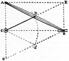
Fig. 113.
§ 77. Parallel Motions.—A parallel motion is a combination of turning pieces in mechanism designed to guide the motion of a reciprocating piece either exactly or approximately in a straight line, so as to avoid the friction which arises from the use of straight guides for that purpose.
Fig. 113 represents an exact parallel motion, first proposed, it is believed, by Scott Russell. The arm CD turns on the axis C, and is jointed at D to the middle of the bar ADB, whose length is double of that of CD, and one of whose ends B is jointed to a slider, sliding in straight guides along the line CB. Draw BE perpendicular to CB, cutting CD produced in E, then E is the instantaneous axis of the bar ADB; and the direction of motion of A is at every instant perpendicular to EA—that is, along the straight line ACa. While the stroke of A is ACa, extending to equal distances on either side of C, and equal to twice the chord of the arc Dd, the stroke of B is only equal to twice the sagitta; and thus A is guided through a comparatively long stroke by the sliding of B through a comparatively short stroke, and by rotatory motions at the joints C, D, B.
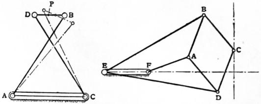
Fig. 114. Fig. 115.
§ 78.* An example of an approximate straight-line motion composed of three bars fixed to a frame is shown in fig. 114. It is due to P. L. Tchebichev of St Petersburg. The links AB and CD are equal in length and are centred respectively at A and C. The ends D and B are joined by a link DB. If the respective lengths are made in the proportions AC : CD : DB = 1 : 1.3 : 0.4 the middle point P of DB will describe an approximately straight line parallel to AC within limits of length about equal to AC. C. N. Peaucellier, a French engineer officer, was the first, in 1864, to invent a linkwork with which an exact straight line could be drawn. The linkwork is shown in fig. 115, from which it will be seen that it consists of a rhombus of four equal bars ABCD, jointed at opposite corners with two equal bars BE and DE. The seventh link AF is equal in length to halt the distance EA when the mechanism is in its central position. The points E and F are fixed. It can be proved that the point C always moves in a straight line at right angles to the line EF. The more general property of the mechanism corresponding to proportions between the lengths FA and EF other than that of equality is that the curve described by the point C is the inverse of the curve described by A. There are other arrangements of bars giving straight-line motions, and these arrangements together with the general properties of mechanisms of this kind are discussed in How to Draw a Straight Line by A. B. Kempe (London, 1877).
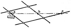
Fig. 116.
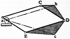
Fig. 117.
§ 79.* The Pantograph.—If a parallelogram of links (fig. 116), be fixed at any one point a in any one of the links produced in either direction, and if any straight line be drawn from this point to cut the links in the points b and c, then the points a, b, c will be in a straight line for all positions of the mechanism, and if the point b be guided in any curve whatever, the point c will trace a similar curve to a scale enlarged in the ratio ab : ac. This property of the parallelogram is utilized in the construction of the pantograph, an instrument used for obtaining a copy of a map or drawing on a different scale. Professor J. J. Sylvester discovered that this property of the parallelogram is not confined to points lying in one line with the fixed point. Thus if b (fig. 117) be any point on the link CD, and if a point c be taken on the link DE such that the triangles CbD and DcE are similar and similarly situated with regard to their respective links, then the ratio of the distances ab and ac is constant, and the angle bac is constant for all positions of the mechanism; so that, if b is guided in any curve, the point c will describe a similar curve turned through an angle bac, the scales of the curves being in the ratio ab to ac. Sylvester called an instrument based on this property a plagiograph or a skew pantograph.
The combination of the parallelogram with a straight-line motion, for guiding one of the points in a straight line, is illustrated in Watt’s parallel motion for steam-engines. (See Steam-engine.)
§ 80.* The Reuleaux System of Analysis.—If two pieces, A and B, (fig. 118) are jointed together by a pin, the pin being fixed, say, to A, the only relative motion possible between the pieces is one of turning about the axis of the pin. Whatever motion the pair of pieces may have as a whole each separate piece shares in common, and this common motion in no way affects the relative motion of A and B. The motion of one piece is said to be completely constrained relatively to the other piece. Again, the pieces A and B (fig. 119) are paired together as a slide, and the only relative motion possible between them now is that of sliding, and therefore the motion of one relatively to the other is completely constrained. The pieces may be paired together as a screw and nut, in which case the relative motion is compounded of turning with sliding.
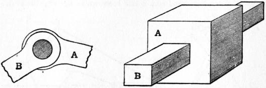
Fig. 118. Fig. 119.
These combinations of pieces are known individually as kinematic pairs of elements, or briefly kinematic pairs. The three pairs mentioned above have each the peculiarity that contact between the two pieces forming the pair is distributed over a surface. Kinematic pairs which have surface contact are classified as lower pairs. Kinematic pairs in which contact takes place along a line only are classified as higher pairs. A pair of spur wheels in gear is an example of a higher pair, because the wheels have contact between their teeth along lines only.
A kinematic link of the simplest form is made by joining up the halves of two kinematic pairs by means of a rigid link. Thus if A1B1 represent a turning pair, and A2B2 a second turning pair, the rigid link formed by joining B1 to B2 is a kinematic link. Four links of this kind are shown in fig. 120 joined up to form a closed kinematic chain.
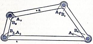
Fig. 120.
In order that a kinematic chain may be made the basis of a mechanism, every point in any link of it must be completely constrained with regard to every other link. Thus in fig. 120 the motion of a point a in the link A1A2 is completely constrained with regard to the link B1B4 by the turning pair A1B1, and it can be proved that the motion of a relatively to the non-adjacent link A3A4 is completely constrained, and therefore the four-bar chain, as it is called, can be and is used as the basis of many mechanisms. Another way of considering the question of constraint is to imagine any one link of the chain fixed; then, however the chain be moved, the path of a point, as a, will always remain the same. In a five-bar chain, if a is a point in a link non-adjacent to a fixed link, its path is indeterminate. Still another way of stating the matter is to say that, if any one link in the chain be fixed, any point in the chain must have only one degree of freedom. In a five-bar chain a point, as a, in a link non-adjacent to the fixed link has two degrees of freedom and the chain cannot therefore be used for a mechanism. These principles may be applied to examine any possible combination of links forming a kinematic chain in order to test its suitability for use as a mechanism. Compound chains are formed by the superposition of two or more simple chains, and in these more complex chains links will be found carrying three, or even more, halves of kinematic pairs. The Joy valve gear mechanism is a good example of a compound kinematic chain.
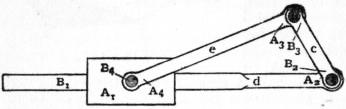
Fig. 121.
A chain built up of three turning pairs and one sliding pair, and known as the slider crank chain, is shown in fig. 121. It will be seen that the piece A1 can only slide relatively to the piece B1, and these two pieces therefore form the sliding pair. The piece A1 carries the pin B4, which is one half of the turning pair A4 B4. The piece A1 together with the pin B4 therefore form a kinematic link A1B4. The other links of the chain are, B1A2, B2B3, A3A4. In order to convert a chain into a mechanism it is necessary to fix one link in it. Any one of the links may be fixed. It follows therefore that there are as many possible mechanisms as there are links in the chain. For example, there is a well-known mechanism corresponding to the fixing of three of the four links of the slider crank chain (fig. 121). If the link d is fixed the chain at once becomes the mechanism of the ordinary steam engine; if the link e is fixed the mechanism obtained is that of the oscillating cylinder steam engine; if the link c is fixed the mechanism becomes either the Whitworth quick-return motion or the slot-bar motion, depending upon the proportion between the lengths of the links c and e. These different mechanisms are called inversions of the slider crank chain. What was the fixed framework of the mechanism in one case becomes a moving link in an inversion.
The Reuleaux system, therefore, consists essentially of the analysis of every mechanism into a kinematic chain, and since each link of the chain may be the fixed frame of a mechanism quite diverse mechanisms are found to be merely inversions of the same kinematic chain. Franz Reuleaux’s Kinematics of Machinery, translated by Sir A. B. W. Kennedy (London, 1876), is the book in which the system is set forth in all its completeness. In Mechanics of Machinery, by Sir A. B. W. Kennedy (London, 1886), the system was used for the first time in an English textbook, and now it has found its way into most modern textbooks relating to the subject of mechanism.
§ 81.* Centrodes, Instantaneous Centres, Velocity Image, Velocity Diagram.—Problems concerning the relative motion of the several parts of a kinematic chain may be considered in two ways, in addition to the way hitherto used in this article and based on the principle of § 34. The first is by the method of instantaneous centres, already exemplified in § 63, and rolling centroids, developed by Reuleaux in connexion with his method of analysis. The second is by means of Professor R. H. Smith’s method already referred to in § 23.
Method 1.—By reference to § 30 it will be seen that the motion of a cylinder rolling on a fixed cylinder is one of rotation about an instantaneous axis T, and that the velocity both as regards direction and magnitude is the same as if the rolling piece B were for the instant turning about a fixed axis coincident with the instantaneous axis. If the rolling cylinder B and its path A now be assumed to receive a common plane motion, what was before the velocity of the point P becomes the velocity of P relatively to the cylinder A, since the motion of B relatively to A still takes place about the instantaneous axis T. If B stops rolling, then the two cylinders continue to move as though they were parts of a rigid body. Notice that the shape of either rolling curve (fig. 91 or 92) may be found by considering each fixed in turn and then tracing out the locus of the instantaneous axis. These rolling cylinders are sometimes called axodes, and a section of an axode in a plane parallel to the plane of motion is called a centrode. The axode is hence the locus of the instantaneous axis, whilst the centrode is the locus of the instantaneous centre in any plane parallel to the plane of motion. There is no restriction on the shape of these rolling axodes; they may have any shape consistent with rolling (that is, no slipping is permitted), and the relative velocity of a point P is still found by considering it with regard to the instantaneous centre.
Reuleaux has shown that the relative motion of any pair of non-adjacent links of a kinematic chain is determined by the rolling together of two ideal cylindrical surfaces (cylindrical being used here in the general sense), each of which may be assumed to be formed by the extension of the material of the link to which it corresponds. These surfaces have contact at the instantaneous axis, which is now called the instantaneous axis of the two links concerned. To find the form of these surfaces corresponding to a particular pair of non-adjacent links, consider each link of the pair fixed in turn, then the locus of the instantaneous axis is the axode corresponding to the fixed link, or, considering a plane of motion only, the locus of the instantaneous centre is the centrode corresponding to the fixed link.
To find the instantaneous centre for a particular link corresponding to any given configuration of the kinematic chain, it is only necessary to know the direction of motion of any two points in the link, since lines through these points respectively at right angles to their directions of motion intersect in the instantaneous centre.
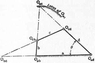
Fig. 122.
To illustrate this principle, consider the four-bar chain shown in fig. 122 made up of the four links, a, b, c, d. Let a be the fixed link, and consider the link c. Its extremities are moving respectively in directions at right angles to the links b and d; hence produce the links b and d to meet in the point Oac. This point is the instantaneous centre of the motion of the link c relatively to the fixed link a, a fact indicated by the suffix ac placed after the letter O. The process being repeated for different values of the angle θ the curve through the several points Oac is the centroid which may be imagined as formed by an extension of the material of the link a. To find the corresponding centroid for the link c, fix c and repeat the process. Again, imagine d fixed, then the instantaneous centre Obd of b with regard to d is found by producing the links c and a to intersect in Obd, and the shapes of the centroids belonging respectively to the links b and d can be found as before. The axis about which a pair of adjacent links turn is a permanent axis, and is of course the axis of the pin which forms the point. Adding the centres corresponding to these several axes to the figure, it will be seen that there are six centres in connexion with the four-bar chain of which four are permanent and two are instantaneous or virtual centres; and, further, that whatever be the configuration of the chain these centres group themselves into three sets of three, each set lying on a straight line. This peculiarity is not an accident or a special property of the four-bar chain, but is an illustration of a general law regarding the subject discovered by Aronhold and Sir A. B. W. Kennedy independently, which may be thus stated: If any three bodies, a, b, c, have plane motion their three virtual centres, Oab, Obc, Oac, are three points on one straight line. A proof of this will be found in The Mechanics of Machinery quoted above. Having obtained the set of instantaneous centres for a chain, suppose a is the fixed link of the chain and c any other link; then Oac is the instantaneous centre of the two links and may be considered for the instant as the trace of an axis fixed to an extension of the link a about which c is turning, and thus problems of instantaneous velocity concerning the link c are solved as though the link c were merely rotating for the instant about a fixed axis coincident with the instantaneous axis.
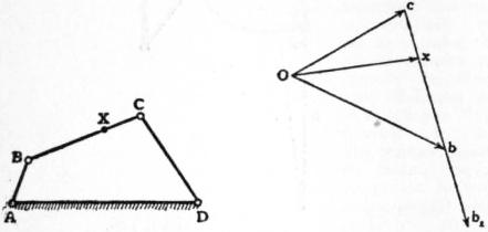
Fig. 123. Fig. 124.
Method 2.—The second method is based upon the vector representation of velocity, and may be illustrated by applying it to the four-bar chain. Let AD (fig. 123) be the fixed link. Consider the link BC, and let it be required to find the velocity of the point B having given the velocity of the point C. The principle upon which the solution is based is that the only motion which B can have relatively to an axis through C fixed to the link CD is one of turning about C. Choose any pole O (fig. 124). From this pole set out Oc to represent the velocity of the point C. The direction of this must be at right angles to the line CD, because this is the only direction possible to the point C. If the link BC moves without turning, Oc will also represent the velocity of the point B; but, if the link is turning, B can only move about the axis C, and its direction of motion is therefore at right angles to the line CB. Hence set out the possible direction of B′s motion in the velocity diagram, namely cb1, at right angles to CB. But the point B must also move at right angles to AB in the case under consideration. Hence draw a line through O in the velocity diagram at right angles to AB to cut cb1 in b. Then Ob is the velocity of the point b in magnitude and direction, and cb is the tangential velocity of B relatively to C. Moreover, whatever be the actual magnitudes of the velocities, the instantaneous velocity ratio of the points C and B is given by the ratio Oc/Ob.