VOLUME XVI SLICE VI Lightfoot, Joseph to Liquidation (continued 4)
Reading edition
Arc Current in Amperes. Height above Road in Feet. Distance apart in Feet. Horizontal Illumination in Candle-Feet.
Maximum. Minimum.
10 20 120 1.85 0.12
10 25 120 1.17 0.15
10 40 120 0.5 0.28
6.8 20 90 1.1 0.21
6.8 40 120 0.3 0.17
As regards distance apart, a very usual practice is to place the lamps at spaces equal to six to ten times their height above the road surface. Blondel (Electrician, 35, p. 846) gives the following rule for the height (h) of the arc to afford the maximum illumination at a distance (d) from the foot of the lamp-post, the continuous current arc being employed:—
For naked arc h = 0.95 d.
” arc in rough glass globe h = 0.85 d.
” ” opaline glob h = ”
” ” opal globe h = 0.5 d.
” ” holophane globe h = 0.5 d.
These figures show that the distribution of light on the horizontal surface is greatly affected by the nature of the enclosing globe. For street illumination naked arcs, although sometimes employed in works and factory yards, are entirely unsuitable, since the result produced on the eye by the bright point of light is to paralyse a part of the retina and contract the pupil, hence rendering the eye less sensitive when directed on feebly illuminated surfaces. Accordingly, diffusing globes have to be employed. It is usual to place the arc in the interior of a globe of from 12 to 18 in. in diameter. This may be made of ground glass, opal glass, or be a dioptric globe such as the holophane. The former two are strongly absorptive, as may be seen from the results of experiments by Guthrie and Redhead. The following table shows the astonishing loss of light due to the use of opal globes:—
Naked Arc. Arc in Clear Globe. Arc in Rough Glass Globe. Arc in Opal Globe.
Mean spherical c.p. 319 235 160 144
Mean hemispherical c.p. 450 326 215 138
Percentage value of transmitted light 100 53 23 19
Percentage absorption 0 47 77 81
By using Trotter’s, Fredureau’s or the holophane globe, the light may be so diffused that the whole globe appears uniformly luminous, and yet not more than 20% of the light is absorbed. Taking the absorption of an ordinary opal globe into account, a 500-watt arc does not usually give more than 500 c.p. as a maximum candle-power. Even with a naked 500-watt arc the mean spherical candle-power is not generally more than 500 c.p., or at the rate of 1 c.p. per watt. The maximum candle-power for a given electrical power is, however, greatly dependent on the current density in the carbon, and to obtain the highest current density the carbons must be as thin as possible. (See T. Hesketh, “Notes on the Electric Arc,” Electrician, 39, p. 707.)
For the efficiency of arcs of various kinds, expressed by the mean hemispherical candle power per ampere and per watt expended in the arc, the following figures were given by L. Andrews (“Long-flame Arc Lamps,” Journal Inst. Elec. Eng., 1906, 37, p. 4).
Candle-power per ampere. Candle-power per watt.
Ordinary open carbon arc 82 1.54
Enclosed carbon arc 55 0.77
Chemical carbon or flame arc 259 5.80
High voltage inclined carbon arc 200 2.24
It will be seen that the flame arc lamp has an enormous advantage over other types in the light yielded for a given electric power consumption.
The practical employment of the electric arc as a means of illumination is dependent upon mechanism for automatically keeping two suitable carbon rods in the proper position, and moving them so as to enable a steady arc to be Arc lamp mechanism. maintained. Means must be provided for holding the carbons in line, and when the lamp is not in operation they must fall together, or come together when the current is switched on, so as to start the arc. As soon as the current passes, they must be moved slightly apart, and gripped in position immediately the current reaches its right value, being moved farther apart if the current increases in strength, and brought together if it decreases. Moreover, it must be possible for a considerable length of carbon to be fed through the lamp as required.
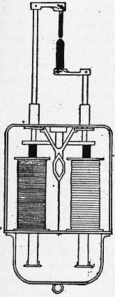
Fig. 13

Fig. 14
One early devised form of arc-lamp mechanism was a system of clockwork driven by a spring or weight, which was started and stopped by the action of an electromagnet; in modern lighthouse lamps a similar mechanism is still employed. W. E. Staite (1847), J. B. L. Foucault (1849), V. L. M. Serrin (1857), J. Duboscq (1858), and a host of later inventors, devised numerous forms of mechanical and clockwork lamps. The modern self-regulating type may be said to have been initiated in 1878 by the differential lamp of F. von Hefner-Alteneck, and the clutch lamp of C. F. Brush. The general principle of the former may be explained as follows: There are two solenoids, placed one above the other. The lower one, of thick wire, is in series with the two carbon rods forming the arc, and is hence called the series coil. Above this there is placed another solenoid of fine wire, which is called the shunt coil. Suppose an iron rod to be placed so as to be partly in one coil and partly in another; then when the coils are traversed by currents, the iron core will be acted upon by forces tending to pull it into these solenoids. If the iron core be attached to one end of a lever, the other end of which carries the upper carbon, it will be seen that if the carbons are in contact and the current is switched on, the series coil alone will be traversed by the current, and its magnetic action will draw down the iron core, and therefore pull the carbons apart and strike the arc. The moment the carbons separate, there will be a difference of potential between them, and the shunt coil will then come into action, and will act on the core so as to draw the carbons together. Hence the two solenoids act in opposition to each other, one increasing and the other diminishing the length of the arc, and maintaining the carbons in the proper position. In the lamp of this type the upper carbon is in reality attached to a rod having a side-rack gearing, with a train of wheels governed by a pendulum. The action of the series coil on the mechanism is to first lock or stop the train, and then lift it as a whole slightly. This strikes the arc. When the arc is too long, the series coil lowers the gear and finally releases the upper carbon, so that it can run down by its own weight. The principle of a shunt and series coil operating on an iron core in opposition is the basis of the mechanism of a number of arc lamps. Thus the lamp invented by F. Krizik and L. Piette, called from its place of origin the Pilsen lamp, comprises an iron core made in the shape of a double cone or spindle (fig. 13), which is so arranged in a brass tube that it can move into or out of a shunt and series coil, wound the one with fine and the other with thick insulated wire, and hence regulate the position of the carbon attached to it. The movement of this core is made to feed the carbons directly without the intervention of any clockwork, as in the case of the Hefner-Alteneck lamp. In the clutch-lamp mechanism the lower carbon is fixed, and the upper carbon rests upon it by its own weight and that of its holder. The latter consists of a long rod passing through guides, and is embraced somewhere by a ring capable of being tilted or lifted by a finger attached to the armature of an electromagnet the coils of which are in series with the arc. When the current passes through the magnet it attracts the armature, and by tilting the ring lifts the upper carbon-holder and hence strikes the arc. If the current diminishes in value, the upper carbon drops a little by its own weight, and the feed of the lamp is thus effected by a series of small lifts and drops of the upper carbon (fig. 14). Another element sometimes employed in arc-lamp mechanism is the brake-wheel regulator. This is a feature of one form of the Brockie and of the Crompton-Pochin lamps. In these the movement of the carbons is effected by a cord or chain which passes over a wheel, or by a rack geared with the brake wheel. When no current is passing through the lamp, the wheel is free to move, and the carbons fall together; but when the current is switched on, the chain or cord passing over the brake wheel, or the brake wheel itself is gripped in some way, and at the same time the brake wheel is lifted so that the arc is struck.
Although countless forms of self-regulating device have been invented for arc lamps, nothing has survived the test of time so well as the typical mechanisms which work with carbon rods in one line, one or both rods being moved by a controlling apparatus as required. The early forms of semi-incandescent arc lamp, such as those of R. Werdermann and others, have dropped out of existence. These were not really true arc lamps, the light being produced by the incandescence of the extremity of a thin carbon rod pressed against a larger rod or block. The once famous Jablochkoff candle, invented in 1876, consisted of two carbon rods about 4 mm. in diameter, placed parallel to each other and separated by a partition of kaolin, steatite or other refractory non-conductor. Alternating currents were employed, and the candle was set in operation by a match or starter of high-resistance carbon paste which connected the tips of the rods. When this burned off, a true arc was formed between the parallel carbons, the separator volatilizing as the carbons burned away. Although much ingenuity was expended on this system of lighting between 1877 and 1881, it no longer exists. One cause of its disappearance was its relative inefficiency in light-giving power compared with other forms of carbon arc taking the same amount of power, and a second equally important reason was the waste in carbons. If the arc of the electric candle was accidentally blown out, no means of relighting existed; hence the great waste in half-burnt candles. H. Wilde, J. C. Jamin, J. Rapieff and others endeavoured to provide a remedy, but without success.
It is impossible to give here detailed descriptions of a fraction of the arc-lamp mechanisms devised, and it must suffice to indicate the broad distinctions between various types. (1) Arc lamps may be either continuous-current or alternating-current lamps. For outdoor public illumination the former are greatly preferable, as owing to the form of the illuminating power-curve they send the light down on the road surface, provided the upper carbon is the positive one. For indoor, public room or factory lighting, inverted arc lamps are sometimes employed. In this case the positive carbon is the lower one, and the lamp is carried in an inverted metallic reflector shield, so that the light is chiefly thrown up on the ceiling, whence it is diffused all round. The alternating-current arc is not only less efficient in mean spherical candle-power per watt of electric power absorbed, but its distribution of light is disadvantageous for street purposes. Hence when arc lamps have to be worked off an alternating-current circuit for public lighting it is now usual to make use of a rectifier, which rectifies the alternating current into an unidirectional though pulsating current. (2.) Arc lamps may be also classified, as above described, into open or enclosed arcs. The enclosed arc can be made to burn for 200 hours with one pair of carbons, whereas open-arc lamps are usually only able to work, 8, 16 or 32 hours without recarboning, even when fitted with double carbons. (3) Arc lamps are further divided into focussing and non-focussing lamps. In the former the lower carbon is made to move up as the upper carbon moves down, and the arc is therefore maintained at the same level. This is advisable for arcs included in a globe, and absolutely necessary in the case of lighthouse lamps and lamps for optical purposes. (4) Another subdivision is into hand-regulated and self-regulating lamps. In the hand-regulated arcs the carbons are moved by a screw attachment as required, as in some forms of search-light lamp and lamps for optical lanterns. The carbons in large search-light lamps are usually placed horizontally. The self-regulating lamps may be classified into groups depending upon the nature of the regulating appliances. In some cases the regulation is controlled only by a series coil, and in others only by a shunt coil. Examples of the former are the original Gülcher and Brush clutch lamp, and some modern enclosed arc lamps; and of the latter, the Siemens “band” lamp, and the Jackson-Mensing lamp. In series coil lamps the variation of the current in the coil throws into or out of action the carbon-moving mechanism; in shunt coil lamps the variation in voltage between the carbons is caused to effect the same changes. Other types of lamp involve the use both of shunt and series coils acting against each other. A further classification of the self-regulating lamps may be found in the nature of the carbon-moving mechanism. This may be some modification of the Brush ring clutch, hence called clutch lamps; or some variety of brake wheel, as employed in Brockie and Crompton lamps; or else some form of electric motor is thrown into or out of action and effects the necessary changes. In many cases the arc-lamp mechanism is provided with a dash-pot, or contrivance in which a piston moving nearly air-tight in a cylinder prevents sudden jerks in the motion of the mechanism, and thus does away with the “hunting” or rapid up-and-down movements to which some varieties of clutch mechanism are liable. One very efficient form is illustrated in the Thomson lamp and Brush-Vienna lamp. In this mechanism a shunt and series coil are placed side by side, and have iron cores suspended to the ends of a rocking arm held partly within them. Hence, according as the magnetic action of the shunt or series coil prevails, the rocking arm is tilted backwards or forwards. When the series coil is not in action the motion is free, and the upper carbon-holder slides down, or the lower one slides up, and starts the arc. The series coil comes into action to withdraw the carbons, and at the same time locks the mechanism. The shunt coil then operates against the series coil, and between them the carbon is fed forwards as required. The control to be obtained is such that the arc shall never become so long as to flicker and become extinguished, when the carbons would come together again with a rush, but the feed should be smooth and steady, the position of the carbons responding quickly to each change in the current.
The introduction of enclosed arc lamps was a great improvement, in consequence of the economy effected in the consumption of carbon and in the cost of labour for trimming. A well-known and widely used form of enclosed arc lamp is the Jandus lamp, which in large current form can be made to burn for two hundred hours without recarboning, and in small or midget form to burn for forty hours, taking a current of two amperes at 100 volts. Such lamps in many cases conveniently replace large sizes of incandescent lamps, especially for shop lighting, as they give a whiter light. Great improvements have also been made in inclined carbon arc lamps. One reason for the relatively low efficiency of the usual vertical rod arrangement is that the crater can only radiate laterally, since owing to the position of the negative carbon no crater light is thrown directly downwards. If, however, the carbons are placed in a downwards slanting position at a small angle like the letter V and the arc formed at the bottom tips, then the crater can emit downwards all the light it produces. It is found, however, that the arc is unsteady unless a suitable magnetic field is employed to keep the arc in position at the carbon tips. This method has been adopted in the Carbone arc, which, by the employment of inclined carbons, and a suitable electromagnet to keep the true arc steady at the ends of the carbons, has achieved considerable success. One feature of the Carbone arc is the use of a relatively high voltage between the carbons, their potential difference being as much as 85 volts.
Arc lamps may be arranged either (i.) in series, (ii.) in parallel or (iii.) in series parallel. In the first case a number, say 20, may be traversed by the same current, in that case supplied at a pressure of 1000 volts. Each must have Arrangement. a magnetic cut-out, so that if the carbons stick together or remain apart the current to the other lamps is not interrupted, the function of such a cut-out being to close the main circuit immediately any one lamp ceases to pass current. Arc lamps worked in series are generally supplied with a current from a constant current dynamo, which maintains an invariable current of, say 10 amperes, independently of the number of lamps on the external circuit. If the lamps, however, are worked in series off a constant potential circuit, such as one supplying at the same time incandescent lamps, provision must be made by which a resistance coil can be substituted for any one lamp removed or short-circuited. When lamps are worked in parallel, each lamp is independent, but it is then necessary to add a resistance in series with the lamp. By special devices three lamps can be worked in series of 100 volt circuits. Alternating-current arc lamps can be worked off a high-tension circuit in parallel by providing each lamp with a small transformer. In some cases the alternating high-tension current is rectified and supplied as a unidirectional current to lamps in series. If single alternating-current lamps have to be worked off a 100 volt alternating-circuit, each lamp must have in series with it a choking coil or economy coil, to reduce the circuit pressure to that required for one lamp. Alternating-current lamps take a larger effective current, and work with a less effective or virtual carbon P.D., than continuous current arcs of the same wattage.
The cost of working public arc lamps is made up of several items. There is first the cost of supplying the necessary electric energy, then the cost of carbons and the labour of recarboning, and, lastly, an item due to depreciation Cost. and repairs of the lamps. An ordinary type of open 10 ampere arc lamp, burning carbons 15 and 9 mm. in diameter for the positive and negative, and working every night of the year from dusk to dawn, uses about 600 ft. of carbons per annum. If the positive carbon is 18 mm. and the negative 12 mm., the consumption of each size of carbon is about 70 ft. per 1000 hours of burning. It may be roughly stated that at the present prices of plain open arc-lamp carbons the cost is about 15s. per 1000 hours of burning; hence if such a lamp is burnt every night from dusk to midnight the annual cost in that respect is about £1, 10s. The annual cost of labour per lamp for trimming is in Great Britain from £2 to £3; hence, approximately speaking, the cost per annum of maintenance of a public arc lamp burning every night from dusk to midnight is about £4 to £5, or perhaps £6, per annum, depreciation and repairs included. Since such a 10 ampere lamp uses half a Board of Trade unit of electric energy every hour, it will take 1000 Board of Trade units per annum, burning every night from dusk to midnight; and if this energy is supplied, say at 1½d. per unit, the annual cost of energy will be about £6, and the upkeep of the lamp, including carbons, labour for trimming and repairs, will be about £10 to £11 per annum. The cost for labour and carbons is considerably reduced by the employment of the enclosed arc lamp, but owing to the absorption of light produced by the inner enclosing globe, and the necessity for generally employing a second outer globe, there is a lower resultant candle-power per watt expended in the arc. Enclosed arc lamps are made to burn without attention for 200 hours, singly on 100 volt circuits, or two in series on 200 volt circuits, and in addition to the cost of carbons per hour being only about one-twentieth of that of the open arc, they have another advantage in the fact that there is a more uniform distribution of light on the road surface, because a greater proportion of light is thrown out horizontally.
It has been found by experience that the ordinary type of open arc lamp with vertical carbons included in an opalescent globe cannot compete in point of cost with modern improvements in gas lighting as a means of street illumination. The violet colour of the light and the sharp shadows, and particularly the non-illuminated area just beneath the lamp, are grave disadvantages. The high-pressure flame arc lamp with inclined chemically treated carbons has, however, put a different complexion on matters. Although the treated carbons cost more than the plain carbons, yet there is a great increase of emitted light, and a 9-ampere flame arc lamp supplied with electric energy at 1½d. per unit can be used for 1000 hours at an inclusive cost of about £s to £6, the mean emitted illumination being at the rate of 4 c.p. per watt absorbed. In the Carbone arc lamp, the carbons are worked at an angle of 15° or 20° to each other and the arc is formed at the lower ends. If the potential difference of the carbons is low, say only 50-60 volts, the crater forms between the tips of the carbons and is therefore more or less hidden. If, however, the voltage is increased to 90-100 then the true flame of the arc is longer and is curved, and the crater forms at the exteme tip of the carbons and throws all its light downwards. Hence results a far greater mean hemispherical candle power (M.H.S.C.P.), so that whereas a 10-ampere 60 volt open arc gives at most 1200 M.H.S.C.P., a Carbone 10-ampere 85 volt arc will give 2700 M.H.S.C.P. Better results still can be obtained with impregnated carbons. But the flame arcs with impregnated carbons cannot be enclosed, so the consumption of carbon is greater, and the carbons themselves are more costly, and leave a greater ash on burning; hence more trimming is required. They give a more pleasing effect for street lighting, and their golden yellow globe of light is more useful than an equally costly plain arc of the open type. This improvement in efficiency is, however, accompanied by some disadvantages. The flame arc is very sensitive to currents of air and therefore has to be shielded from draughts by putting it under an “economizer” or chamber of highly refractory material which surrounds the upper carbon, or both carbon tips, if the arc is formed with inclined carbons. (For additional information on flame arc lamps see a paper by L. B. Marks and H. E. Clifford, Electrician, 1906, 57, p. 975.)
2. Incandescent Lamps.—Incandescent electric lighting, although not the first, is yet in one sense the most obvious method of utilizing electric energy for illumination. It was evolved from the early observed fact that a conductor is heated when traversed by an electric current, and that if it has a high resistance and a high melting-point it may be rendered incandescent, and therefore become a source of light. Naturally every inventor turned his attention to the employment of wires of refractory metals, such as platinum or alloys of platinum-iridium, &c., for the purpose of making an incandescent lamp. F. de Moleyns experimented in 1841, E. A. King and J. W. Starr in 1845, J. J. W. Watson in 1853, and W. E. Staite in 1848, but these inventors achieved no satisfactory result. Part of their want of success is attributable to the fact that the problem of the economical production of electric current by the dynamo machine had not then been solved. In 1878 T. A. Edison devised lamps in which a platinum wire was employed as the light-giving agent, carbon being made to adhere round it by pressure. Abandoning this, he next directed his attention to the construction of an “electric candle,” consisting of a thin cylinder or rod formed of finely-divided metals, platinum, iridium, &c., mixed with refractory oxides, such as magnesia, or zirconia, lime, &c. This refractory body was placed in a closed vessel and heated by being traversed by an electric current. In a further improvement he proposed to use a block of refractory oxide, round which a bobbin of fine platinum or platinum-iridium wire was coiled. Every other inventor who worked at the problem of incandescent lighting seems to have followed nearly the same path of invention. Long before this date, however, the notion of employing carbon as a substance to be heated by the current had entered the minds of inventors; even in 1845 King had employed a small rod of plumbago as the substance to be heated. It was obvious, however, that carbon could only be so heated when in a space destitute of oxygen, and accordingly King placed his plumbago rod in a barometric vacuum. S. W. Konn in 1872, and S. A. Kosloff in 1875, followed in the same direction.
No real success attended the efforts of inventors until it was finally recognized, as the outcome of the work by J. W. Swan, T. A. Edison, and, in a lesser degree, St. G. Lane Fox and W. E. Sawyer and A. Man, that the conditions Carbon filament lamp. of success were as follow: First, the substance to be heated must be carbon in the form of a thin wire rod or thread, technically termed a filament; second, this must be supported and enclosed in a vessel formed entirely of glass; third, the vessel must be exhausted as perfectly as possible; and fourth, the current must be conveyed into and out of the carbon filament by means of platinum wires hermetically sealed through the glass.
One great difficulty was the production of the carbon filament. King, Sawyer, Man and others had attempted to cut out a suitably shaped piece of carbon from a solid block; but Edison and Swan were the first to show that the proper solution of the difficulty was to carbonize an organic substance to which the necessary form had been previously given. For this purpose cardboard, paper and ordinary thread were originally employed, and even, according to Edison, a mixture of lampblack and tar rolled out into a fine wire and bent into a spiral. At one time Edison employed a filament of bamboo, carbonized after being bent into a horse-shoe shape. Swan used a material formed by treating ordinary crochet cotton-thread with dilute sulphuric acid, the “parchmentized thread” thus produced being afterwards carbonized. In the modern incandescent lamp the filament is generally constructed by preparing first of all a form of soluble cellulose. Carefully purified cotton-wool is dissolved in some solvent, such as a solution of zinc chloride, and the viscous material so formed is forced by hydraulic pressure through a die. The long thread thus obtained, when hardened, is a semi-transparent substance resembling cat-gut, and when carefully carbonized at a high temperature gives a very dense and elastic form of carbon filament. It is cut into appropriate lengths, which after being bent into horse-shoes, double-loops, or any other shape desired, are tied or folded round carbon formers and immersed in plumbago crucibles, packed in with finely divided plumbago. The crucibles are then heated to a high temperature in an ordinary combustion or electric furnace, whereby the organic matter is destroyed, and a skeleton of carbon remains. The higher the temperature at which this carbonization is conducted, the denser is the resulting product. The filaments so prepared are sorted and measured, and short leading-in wires of platinum are attached to their ends by a carbon cement or by a carbon depositing process, carried out by heating electrically the junction of the carbon and platinum under the surface of a hydrocarbon liquid. They are then mounted in bulbs of lead glass having the same coefficient of expansion as platinum, through the walls of which, therefore, the platinum wires can be hermetically sealed. The bulbs pass into the exhausting-room, where they are exhausted by some form of mechanical or mercury pump. During this process an electric current is sent through the filament to heat it, in order to disengage the gases occluded in the carbon, and exhaustion must be so perfect that no luminous glow appears within the bulb when held in the hand and touched against one terminal of an induction coil in operation.
In the course of manufacture a process is generally applied to the carbon which is technically termed “treating.” The carbon filament is placed in a vessel surrounded by an atmosphere of hydrocarbon, such as coal gas or vapour of benzol. If current is then passed through the filament the hydrocarbon vapour is decomposed, and carbon is thrown down upon the filament in the form of a lustrous and dense deposit having an appearance like steel when seen under the microscope. This deposited carbon is not only much more dense than ordinary carbonized organic material, but it has a much lower specific electric resistance. An untreated carbon filament is generally termed the primary carbon, and a deposited carbon the secondary carbon. In the process of treating, the greatest amount of deposit is at any places of high resistance in the primary carbon, and hence it tends to cover up or remedy the defects which may exist. The bright steely surface of a well-treated filament is a worse radiator than the rougher black surface of an untreated one; hence it does not require the expenditure of so much electric power to bring it to the same temperature, and probably on account of its greater density it ages much less rapidly.
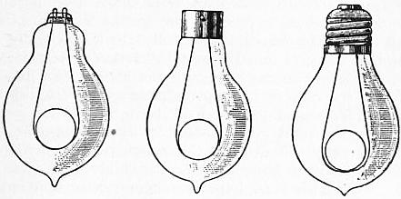
Fig. 15.
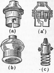
Fig. 16.—Incandescent Lamp Sockets.
Finally, the lamp is provided with a collar having two sole plates on it, to which the terminal wires are attached, or else the terminal wires are simply bent into two loops; in a third form, the Edison screw terminal, it is provided with a central metal plate, to which one end of the filament is connected, the other end being joined to a screw collar. The collars and screws are formed of thin brass embedded in plaster of Paris, or in some material like vitrite or black glass (fig. 15). To put the lamp into connexion with the circuit supplying the current, it has to be fitted into a socket or holder. Three of the principal types of holder in use are the bottom contact (B.C.) or Dornfeld socket, the Edison screw-collar socket and the Swan or loop socket. In the socket of C. Dornfeld (fig. 16, a and a′) two spring pistons, in contact with the two sides of the circuit, are fitted into the bottom of a short metallic tube having bayonet joint slots cut in the top. The brass collar on the lamp has two pins, by means of which a bayonet connexion is made between it and the socket; and when this is done, the spring pins are pressed against the sole plates on the lamp. In the Edison socket (fig. 16, b) a short metal tube with an insulating lining has on its interior a screw sleeve, which is in connexion with one wire of the circuit; at the bottom of the tube, and insulated from the screw sleeve, is a central metal button, which is in connexion with the other side of the circuit. On screwing the lamp into the socket, the screw collar of the lamp and the boss or plate at the base of the lamp make contact with the corresponding parts of the socket, and complete the connexion. In some cases a form of switch is included in the socket, which is then termed the key-holder. For loop lamps the socket consists of an insulated block, having on it two little hooks, which engage with the eyes of the lamp. This insulating block also carries some form of spiral spring or pair of spring loops, by means of which the lamp is pressed away from the socket, and the eyes kept tight by the hooks. This spring or Swan socket (fig. 16, c) is found useful in places where the lamps are subject to vibration, for in such cases the Edison screw collar cannot well be used, because the vibration loosens the contact of the lamp in the socket. The sockets may be fitted with appliances for holding ornamental shades or conical reflectors.
The incandescent filament being a very brilliant line of light, various devices are adopted for moderating its brilliancy and distributing the light. A simple method is to sand-blast the exterior of the bulb, whereby it acquires an appearance similar to that of ground glass, or the bare lamp may be enclosed in a suitable glass shade. Such shades, however, if made of opalescent or semi-opaque glass, absorb 40 to 60% of the light; hence various forms of dioptric shade have been invented, consisting of clear glass ruled with prismatic grooves in such a manner as to diffuse the light without any very great absorption. Invention has been fertile in devising etched, coloured, opalescent, frosted and ornamental shades for decorative purposes, and in constructing special forms for use in situations, such as mines and factories for explosives, where the globe containing the lamp must be air-tight. High candle-power lamps, 500, 1000 and upwards, are made by placing in one large glass bulb a number of carbon filaments arranged in parallel between two rings, which are connected with the main leading-in wires. When incandescent lamps are used for optical purposes it is necessary to compress the filament into a small space, so as to bring it into the focus of a lens or mirror. The filament is then coiled or crumpled up into a spiral or zigzag form. Such lamps are called focus lamps.
Incandescent lamps are technically divided into high and low voltage lamps, high and low efficiency lamps, standard and fancy lamps. The difference between high and low efficiency lamps is based upon the relation of the Classification of lamps. power absorbed by the lamp to the candle-power emitted. Every lamp when manufactured is marked with a certain figure, called the marked volts. This is understood to be the electromotive force in volts which must be applied to the lamp terminals to produce through the filament a current of such magnitude that the lamp will have a practically satisfactory life, and give in a horizontal direction a certain candle-power, which is also marked upon the glass. The numerical product of the current in amperes passing through the lamp, and the difference in potential of the terminals measured in volts, gives the total power taken up by the lamp in watts; and this number divided by the candle-power of the lamp (taking generally a horizontal direction) gives the watts per candle-power. This is an important figure, because it is determined by the temperature; it therefore determines the quality of the light emitted by the lamp, and also fixes the average duration of the filament when rendered incandescent by a current. Even in a good vacuum the filament is not permanent. Apart altogether from accidental defects, the carbon is slowly volatilized, and carbon molecules are also projected in straight lines from different portions of the filament. This process not only causes a change in the nature of the surface of the filament, but also a deposit of carbon on the interior of the bulb, whereby the glass is blackened and the candle-power of the lamp reduced. The volatilization increases very rapidly as the temperature rises. Hence at points of high resistance in the filament, more heat being generated, a higher temperature is attained, and the scattering of the carbon becomes very rapid; in such cases the filament is sooner or later cut through at the point of high resistance. In order that incandescent lighting may be practically possible, it is essential that the lamps shall have a certain average life, that is, duration; and this useful duration is fixed not merely by the possibility of passing a current through the lamp at all, but by the rate at which the candle-power diminishes. The decay of candle-power is called the ageing of the lamp, and the useful life of the lamp may be said to be that period of its existence before it has deteriorated to a point when it gives only 75% of its original candle-power. It is found that in practice carbon filament lamps, as at present made, if worked at a higher efficiency than 2½ watts per candle-power, exhibit a rapid deterioration in candle-power and an abbreviated life. Hence lamp manufacturers classify lamps into various classes, marked for use say at 2½, 3, 3½ and 4 watts per candle. A 2½ watt per candle lamp would be called a high-efficiency lamp, and a 4 watt per candle lamp would be called a low-efficiency lamp. In ordinary circumstances the low-efficiency lamp would probably have a longer life, but its light would be less suitable for many purposes of illumination in which colour discrimination is required.
The possibility of employing high-efficiency lamps depends greatly on the uniformity of the electric pressure of the supply. If the voltage is exceedingly uniform, then high-efficiency lamps can be satisfactorily employed; but they are not adapted for standing the variations in pressure which are liable to occur with public supply-stations, since, other things being equal, their filaments are less substantial. The classification into high and low voltage lamps is based upon the watts per candle-power corresponding to the marked volts. When incandescent lamps were first introduced, the ordinary working voltage was 50 or 100, but now a large number of public supply-stations furnish current to consumers at a pressure of 200 or 250 volts. This increase was necessitated by the enlarging area of supply in towns, and therefore the necessity for conveying through the same subterranean copper cables a large supply of electric energy without increasing the maximum current value and the size of the cables. This can only be done by employing a higher working electromotive force; hence arose a demand for incandescent lamps having marked volts of 200 and upwards, technically termed high-voltage lamps. The employment of higher pressures in public supply-stations has necessitated greater care in the selection of the lamp fittings, and in the manner of carrying out the wiring work. The advantages, however, of higher supply pressures, from the point of view of supply-stations, are undoubted. At the same time the consumer desired a lamp of a higher efficiency than the ordinary carbon filament lamp. The demand for this stimulated efforts to produce improved carbon lamps, and it was found that if the filament were exposed to a very high temperature, 3000° C. in an electric furnace, it became more refractory and was capable of burning in a lamp at an efficiency of 2½ watts per c.p. Inventors also turned their attention to substances other than carbon which can be rendered incandescent by the electric current.
The luminous efficiency of any source of light, that is to say, the percentage of rays emitted which affect the eye as light compared with the total radiation, is dependent upon its temperature. In an ordinary oil lamp the luminous Oxide filaments. rays do not form much more than 3% of the total radiation. In the carbon-filament incandescent lamp, when worked at about 3 watts per candle, the luminous efficiency is about 5%; and in the arc lamp the radiation from the crater contains about 10 to 15% of eye-affecting radiation. The temperature of a carbon filament working at about 3 watts per candle is not far from the melting-point of platinum, that is to say, is nearly 1775° C. If it is worked at a higher efficiency, say 2.5 watts per candle-power, the temperature rises rapidly, and at the same time the volatilization and molecular scattering of the carbon is rapidly increased, so that the average duration of the lamp is very much shortened. An improvement, therefore, in the efficiency of the incandescent lamp can only be obtained by finding some substance which will endure heating to a higher temperature than the carbon filament. Inventors turned their attention many years ago, with this aim, to the refractory oxides and similar substances. Paul Jablochkoff in 1877 described and made a lamp consisting of a piece of kaolin, which was brought to a state of incandescence first by passing over it an electric spark, and afterwards maintained in a state of incandescence by a current of lower electromotive force. Lane Fox and Edison, in 1878, proposed to employ platinum wires covered with films of lime, magnesia, steatite, or with the rarer oxides, zirconia, thoria, &c.; and Lane Fox, in 1879, suggested as an incandescent substance a mixture of particles of carbon with the earthy oxides. These earthy oxides—magnesia, lime and the oxides of the rare earths, such as thoria, zirconia, erbia, yttria, &c.—possess the peculiarity that at ordinary temperatures they are practically non-conductors, but at very high temperatures their resistance at a certain point rapidly falls, and they become fairly good conductors. Hence if they can once be brought into a state of incandescence a current can pass through them and maintain them in that state. But at this temperature they give up oxygen to carbon; hence no mixtures of earthy oxides with carbon are permanent when heated, and failure has attended all attempts to use a carbon filament covered with such substances as thoria, zirconia or other of the rare oxides.
H. W. Nernst in 1897, however, patented an incandescent lamp in which the incandescent body consists entirely of a slender rod or filament of magnesia. If such a rod is heated by the oxy-hydrogen blowpipe to a high Nernst lamp. temperature it becomes conductive, and can then be maintained in an intensely luminous condition by passing a current through it after the flame is withdrawn. Nernst found that by mixing together, in suitable proportions, oxides of the rare earths, he was able to prepare a material which can be formed into slender rods and threads, and which is rendered sufficiently conductive to pass a current with an electromotive force as low as 100 volts, merely by being heated for a few moments with a spirit lamp, or even by the radiation from a neighbouring platinum spiral brought to a state of incandescence.
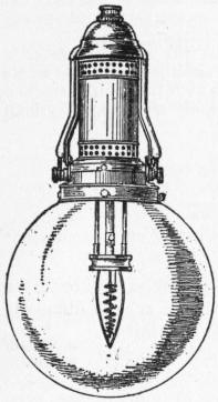
Fig. 17.—Nernst Lamp A Type.
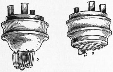
Fig. 18.—Nernst Lamp, Burners for B Type. a, low voltage; b, high voltage.
The Nernst lamp, therefore (fig. 17), consists of a slender rod of the mixed oxides attached to platinum wires by an oxide paste. Oxide filaments of this description are not enclosed in an exhausted glass vessel, and they can be brought, without risk of destruction, to a temperature considerably higher than a carbon filament; hence the lamp has a higher luminous efficiency. The material now used for the oxide rod or “glower” of Nernst lamps is a mixture of zirconia and yttria, made into a paste and squirted or pressed into slender rods. This material is non-conductive when cold, but when slightly heated it becomes conductive and then falls considerably in resistance. The glower, which is straight in some types of the lamp but curved in others, is generally about 3 or 4 cm. long and 1 or 2 mm. in diameter. It is held in suitable terminals, and close to it, or round it, but not touching it, is a loose coil of platinum wire, also covered with oxide and called the “heater” (fig. 18). In series with it is a spiral of iron wire, enclosed in a bulb full of hydrogen, which is called the “ballast resistance.” The socket also contains a switch controlled by an electromagnet. When the current is first switched on it passes through the heater coil which, becoming incandescent, by radiation heats the glower until it becomes conductive. The glower then takes current, becoming itself brilliantly incandescent, and the electromagnet becoming energized switches the heater coil out of circuit. The iron ballast wire increases in resistance with increase of current, and so operates to keep the total current through the glower constant in spite of small variations of circuit voltage. The disadvantages of the lamp are (1) that it does not light immediately after the current is switched on and is therefore not convenient for domestic use; (2) that it cannot be made in small light units such as 5 c.p.; (3) that the socket and fixture are large and more complicated than for the carbon filament lamp. But owing to the higher temperature, the light is whiter than that of the carbon glow lamp, and the efficiency or candle power per watt is greater. Since, however, the lamp must be included in an opal globe, some considerable part of this last advantage is lost. On the whole the lamp has found its field of operation rather in external than in domestic lighting.
Great efforts were made in the latter part of the 19th century and the first decade of the 20th to find a material for the filament of an incandescent lamp which could replace carbon and yet not require a preliminary heating like the Metallic filament lamps. oxide glowers. This resulted in the production of refractory metallic filament lamps made of osmium, tantalum, tungsten and other rare metals. Auer von Welsbach suggested the use of osmium. This metal cannot be drawn into wire on account of its brittleness, but it can be made into a filament by mixing the finely divided metal with an organic binding material which is carbonized in the usual way at a high temperature, the osmium particles then cohering. The difficulty has hitherto been to construct in this way metallic filament lamps of low candle power (16 c.p.) for 220 volt circuits, but this is being overcome. When used on modern supply circuits of 220 volts a number of lamps may be run in series, or a step-down transformer employed.
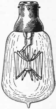
Fig. 19.—Tantalum Lamp.
The next great improvement came when W. von Bolton produced the tantalum lamp in 1904. There are certain metals known to have a melting point about 2000° C. or upwards, and of these tantalum is one. It can be produced from the potassium tantalo-fluoride in a pulverulent form. By carefully melting it in vacuo it can then be converted into the reguline form and drawn into wire. In this condition it has a density of 16.6 (water = 1), is harder than platinum and has greater tensile strength than steel, viz. 95 kilograms per sq. mm., the value for good steel being 70 to 80 kilograms per sq. mm. The electrical resistance at 15° C. is 0.146 ohms per metre with section of 1 sq. mm. after annealing at 1900° C. in vacuo and therefore about 6 times that of mercury; the temperature coefficient is 0.3 per degree C. At the temperature assumed in an incandescent lamp when working at 1.5 watts per c.p. the resistance is 0.830 ohms per metre with a section of 1 sq. mm. The specific heat is 0.0365. Bolton invented methods of producing tantalum in the form of a long fine wire 0.05 mm. in diameter. To make a 25 c.p. lamp 650 mm., or about 2 ft., of this wire are wound backwards and forwards zigzag on metallic supports carried on a glass frame, which is sealed into an exhausted glass bulb. The tantalum lamp so made (fig. 19), working on a 110 volt circuit takes 0.36 amperes or 39 watts, and hence has an efficiency of about 1.6 watts per c.p. The useful life, that is the time in which it loses 20% of its initial candle power, is about 400-500 hours, but in general a life of 800-1000 hours can be obtained. The bulb blackens little in use, but the life is said to be shorter with alternating than with direct current. When worked on alternating current circuits the filament after a time breaks up into sections which become curiously sheared with respect to each other but still maintain electrical contact. The resistance of tantalum increases with the temperature; hence the temperature coefficient is positive, and sudden rises in working voltage do not cause such variations in candle-power as in the case of the carbon lamp.
Patents have also been taken out for lamps made with filaments of such infusible metals as tungsten and molybdenum, and Siemens and Halske, Sanders and others, have protected methods for employing zirconium and other rare metals. According to the patents of Sanders (German patents Nos. 133701, 137568, 137569) zirconium filaments are manufactured from the hydrogen or nitrogen compounds of the rare earths by the aid of some organic binding material. H. Kuzel of Vienna (British Patent No. 28154 of 1904) described methods of making metallic filaments from any metal. He employs the metals in a colloidal condition, either as hydrosol, organosol, gel, or colloidal suspension. The metals are thus obtained in a gelatinous form, and can be squirted into filaments which are dried and reduced to the metallic form by passing an electric current through them (Electrician, 57, 894). This process has a wide field of application, and enables the most refractory and infusible metals to be obtained in a metallic wire form. The zirconium and tungsten wire lamps are equal to or surpass the tantalum lamp in efficiency and are capable of giving light, with a useful commercial life, at an efficiency of about one watt per candle. Lamps called osram lamps, with filaments composed of an alloy of osmium and tungsten (wolfram), can be used with a life of 1000 hours when run at an efficiency of about 1.5 watts per candle.
Tungsten lamps are made by the processes of Just and Hanaman (German patent No. 154262 of 1903) and of Kuzel, and at a useful life of 1000 hours, with a falling off in light-giving power of only 10-15%, they have been found to work at an efficiency of one to 1.25 watts per c.p. Further collected information on modern metallic wire lamps and the patent literature thereof will be found in an article in the Engineer for December 7, 1906.
Mention should also be made of the Helion filament glow lamp in which the glower is composed largely of silicon, a carbon filament being used as a base. This filament is said to have a number of interesting qualities and an efficiency of about 1 watt per candle (see the Electrician, 1907, 58, p. 567).
The mercury vapour lamps of P. Cooper-Hewitt, C. O. Bastian and others have a certain field of usefulness. If a glass tube, highly exhausted, contains mercury vapour and a mercury cathode and iron anode, a current can be Mercury vapour lamps. passed through it under high electromotive force and will then be maintained when the voltage is reduced. The mercury vapour is rendered incandescent and glows with a brilliant greenish light which is highly actinic, but practically monochromatic, and is therefore not suitable for general illumination because it does not reveal objects in their daylight colours. It is, however, an exceedingly economical source of light. A 3-ampere Cooper-Hewitt mercury lamp has an efficiency of 0.15 to 0.33 watts per candle, or practically the same as an arc lamp, and will burn for several thousand hours. A similar lamp with mercury vapour included in a tube of uviol glass specially transparent to ultra-violet light (prepared by Schott & Co. of Jena) seems likely to replace the Finsen arc lamp in the treatment of lupus. Many attempts have been made to render the mercury vapour lamp polychromatic by the use of amalgams of zinc, sodium and bismuth in place of pure mercury for the negative electrode.
An important matter in connexion with glow lamps is their photometry. The arrangement most suitable for the photometry and testing of incandescent lamps is a gallery or room large enough to be occupied by several workers, Photometry of glow lamps. the walls being painted dead black. The photometer, preferably one of the Lummer-Brodhun form, is set up on a gallery or bench. On one side of it must be fixed a working standard, which as first suggested by Fleming is preferably a large bulb incandescent lamp with a specially “aged” filament. Its candle-power can be compared, at regular intervals and known voltages, with that of some accepted flame standard, such as the 10 candle pentane lamp of Vernon Harcourt. In a lamp factory or electrical laboratory it is convenient to have a number of such large bulb standard lamps. This working standard should be maintained at a fixed distance on one side of the photometer, such that when worked at a standard voltage it creates an illumination of one candle-foot on one side of the photometer disk. The incandescent lamp to be examined is then placed on the other side of the photometer disk on a travelling carriage, so that it can be moved to and fro. Arrangements must be made to measure the current and the voltage of this lamp under test, and this is most accurately accomplished by employing a potentiometer (q.v.). The holder which carries the lamp should allow the lamp to be held with its axis in any required position; in making normal measurements the lamp should have its axis vertical, the filament being so situated that none of the turns or loops overlies another as seen from the photometer disk. Observations can then be made of the candle-power corresponding to different currents and voltages.
The candle-power of the lamp varies with the other variables in accordance with exponential laws of the following kind:—
If A is the current in amperes through the lamp, V the voltage or terminal potential difference, W the power absorbed in watts, c.p. the maximum candle-power, and a, b, c, &c., constants, it has been found that A and c.p. are connected by an exponential law such that
c.p. = aAx
For carbon filament lamps x is a number lying between 5 and 6, generally equal to 5.5 or 5.6. Also it has been found that c.p. = bW³ very nearly, and that
c.p. = cVy nearly
where c is some other constant, and for carbon filaments y is a number nearly equal to 6. It is obvious that if the candle-power of the lamp varies very nearly as the 6th power of the current and of the voltage, the candle-power must vary as the cube of the wattage.
Sir W. de W. Abney and E. R. Festing have also given a formula connecting candle-power and watts equivalent to c.p. = (W − d)² where d is a constant.
In the case of the tantalum lamp the exponent x has a value near to 6, but the exponent y is a number near to 4, and the same for the osmium filament. Hence for these metallic glowers a certain percentage variation of voltage does not create so great a variation in candle-power as in the case of the carbon lamp.
Curves delineating the relation of these variables for any incandescent lamp are called its characteristic-curves. The life or average duration is a function of W/c.p., or of the watts per candle-power, and therefore of the voltage at which the lamp is worked. It follows from the above relation that the watts per candle-power vary inversely as the fourth power of the voltage.
From limited observations it seems that the average life of a carbon-filament lamp varies as the fifth or sixth power of the watts per candle-power. If V is the voltage at which the lamp is worked and L is its average life, then L varies roughly as the twenty-fifth power of the reciprocal of the voltage, or
L = aV−25.
A closer approximation to experience is given by the formula
log10L = 13.5 − V − V² .
10 20,000
(See J. A. Fleming, “Characteristic Curves of Incandescent Lamps,” Phil. Mag. May 1885).
All forms of incandescent or glow lamps are found to deteriorate in light-giving power with use. In the case of carbon filaments this is due to two causes. As already explained, carbon is scattered from the filament and deposited Ageing of lamps. upon the glass, and changes also take place in the filament which cause it to become reduced in temperature, even when subjected to the same terminal voltage. In many lamps it is found that the first effect of running the lamp is slightly to increase its candle-power, even although the voltage be kept constant; this is the result of a small decrease in the resistance of the filament. The heating to which it is subjected slightly increases the density of the carbon at the outset; this has the effect of making the filament lower in resistance, and therefore it takes more current at a constant voltage. The greater part, however, of the subsequent decay in candle-power is due to the deposit of carbon upon the bulb, as shown by the fact that if the filament is taken out of the bulb and put into a new clean bulb the candle-power in the majority of cases returns to its original value. For every lamp there is a certain point in its career which may be called the “smashing-point,” when the candle-power falls below a certain percentage of the original value, and when it is advantageous to replace it by a new one. Variations of pressure in the electric supply exercise a prejudicial effect upon the light-giving qualities of incandescent lamps. If glow lamps, nominally of 100 volts, are supplied from a public lighting-station, in the mains of which the pressure varies between 90 and 110 volts, their life will be greatly abbreviated, and they will become blackened much sooner than would be the case if the pressure were perfectly constant. Since the candle-power of the lamp varies very nearly as the fifth or sixth power of the voltage, it follows that a variation of 10% in the electromotive force creates a variation of nearly 50% in the candle-power. Thus a 16 candle-power glow lamp, marked for use at 100 volts, was found on test to give the following candle-powers at voltages varying between 90 and 105: At 105 volts it gave 22.8 c.p.; at 100 volts, 16.7 c.p.; at 95 volts, 12.2 c.p.; and at 90 volts, 8.7 c.p. Thus a variation of 25% in the candle-power was caused by a variation in voltage of only 5%. The same kind of variation in working voltage exercises also a marked effect upon the average duration of the lamp. The following figures show the results of some tests on typical 3.1 watt lamps run at voltages above the normal, taking the average life when worked at the marked volts (namely, 100) as 1000 hours:
At 101 volts the life was 818 hours.
” 102 ” ” 681 ”
” 103 ” ” 662 ”
” 104 ” ” 452 ”
” 105 ” ” 374 ”
” 106 ” ” 310 ”
Self-acting regulators have been devised by which the voltage at the points of consumption is kept constant, even although it varies at the point of generation. If, however, Voltage regulators. such a device is to be effective, it must operate very quickly, as even the momentary effect of increased pressure is felt by the lamp. It is only therefore where the working pressure can be kept exceedingly constant that high-efficiency lamps can be advantageously employed, otherwise the cost of lamp renewals more than counterbalances the economy in the cost of power. The slow changes that occur in the resistance of the filament make themselves evident by an increase in the watts per candle-power. The following table shows some typical figures indicating the results of ageing in a 16 candle-power carbon-filament glow lamp:—
Hours run. Candle-Power. Watts per Candle-Power.
0 16.0 3.16
100 15.8 3.26
200 15.86 3.13
300 15.68 3.37
400 15.41 3.53
500 15.17 3.51
600 14.96 3.54
700 14.74 3.74
The gradual increase in watts per candle-power shown by this table does not imply necessarily an increase in the total power taken by the lamp, but is the consequence of the decay in candle-power produced by the blackening of the lamp. Therefore, to estimate the value of an incandescent lamp the user must take into account not merely the price of the lamp and the initial watts per candle-power, but the rate of decay of the lamp.
The scattering of carbon from the filament to the glass bulb produces interesting physical effects, which have been studied by T. A. Edison, W. H. Preece and J. A. Fleming. If into an ordinary carbon-filament glow lamp a Edison effect. platinum plate is sealed, not connected to the filament but attached to a third terminal, then it is found that when the lamp is worked with continuous current a galvanometer connected in between the middle plate and the positive terminal of the lamp indicates a current, but not when connected in between the negative terminal of the lamp and the middle plate. If the middle plate is placed between the legs of a horse-shoe-shaped filament, it becomes blackened most quickly on the side facing the negative leg. This effect, commonly called the Edison effect, is connected with an electric discharge and convection of carbon which takes place between the two extreme ends of the filament, and, as experiment seems to show, consists in the conveyance of an electric charge, either by carbon molecules or by bodies smaller than molecules. There is, however, an electric discharge between the ends of the filament, which rapidly increases with the temperature of the filament and the terminal voltage; hence one of the difficulties of manufacturing high-voltage glow lamps, that is to say, glow lamps for use on circuits having an electromotive force of 200 volts and upwards, is the discharge from one leg of the filament to the other.
A brief allusion may be made to the mode of use of incandescent lamps for interior and private lighting. At the present time hardly any other method of distribution is adopted than that of an arrangement in parallel; that is Domestic use. to say, each lamp on the circuit has one terminal connected to a wire which finally terminates at one pole of the generator, and its other terminal connected to a wire leading to the other pole. The lamp filaments are thus arranged between the conductors like the rungs of a ladder. In series with each lamp is placed a switch and a fuse or cut-out. The lamps themselves are attached to some variety of ornamental fitting, or in many cases suspended by a simple pendant, consisting of an insulated double flexible wire attached at its upper end to a ceiling rose, and carrying at the lower end a shade and socket in which the lamp is placed. Lamps thus hung head downwards are disadvantageously used because their end-on candle-power is not generally more than 60% of their maximum candle-power. In interior lighting one of the great objects to be attained is uniformity of illumination with avoidance of harsh shadows. This can only be achieved by a proper distribution of the lamps. It is impossible to give any hard and fast rules as to what number must be employed in the illumination of any room, as a great deal depends upon the nature of the reflecting surfaces, such as the walls, ceilings, &c. As a rough guide, it may be stated that for every 100 sq. ft. of floor surface one 16 candle-power lamp placed about 8 ft. above the floor will give a dull illumination, two will give a good illumination and four will give a brilliant illumination. We generally judge of the nature of the illumination in a room by our ability to read comfortably in any position. That this may be done, the horizontal illumination on the book should not be less than one candle-foot. The following table shows approximately the illuminations in candle-feet, in various situations, derived from actual experiments:—
In a well-lighted room on the floor or tables 1.0 to 3.0 c.f.
On a theatre stage 3.0 to 4.0 c.f.
On a railway platform .05 to .5 c.f.
In a picture gallery .65 to 3.5 c.f.
The mean daylight in May in the interior of a room 30.0 to 40.0 c.f.
In full sunlight 7000 to 10,000 c.f.
In full moonlight 1/60th to 1/100th c.f.
From an artistic point of view, one of the worst methods of lighting a room is by pendant lamps, collected in single centres in large numbers. The lights ought to be distributed in different portions of the room, and so shaded that the light is received only by reflection from surrounding objects. Ornamental effects are frequently produced by means of candle lamps in which a small incandescent lamp, imitating the flame of a candle, is placed upon a white porcelain tube as a holder, and these small units are distributed and arranged in electroliers and brackets. For details as to the various modes of placing conducting wires in houses, and the various precautions for safe usage, the reader is referred to the article Electricity Supply. In the case of low voltage metallic filament lamps when the supply is by alternating current there is no difficulty in reducing the service voltage to any lower value by means of a transformer. In the case of direct current the only method available for working such low voltage lamps off higher supply voltages is to arrange the lamps in series.
Additional information on the subjects treated above may be found in the following books and original papers:—
Mrs Ayrton, The Electric Arc (London, 1900); Houston and Kennelly, Electric Arc Lighting and Electric Incandescent Lighting; S. P. Thompson, The Arc Light, Cantor Lectures, Society of Arts (1895); H. Nakano, “The Efficiency of the Arc Lamp,” Proc. American Inst. Elec. Eng. (1889); A. Blondel, “Public and Street Lighting by Arc Lamps,” Electrician, vols. xxxv. and xxxvi. (1895); T. Heskett, “Notes on the Electric Arc,” Electrician, vol. xxxix. (1897); G. S. Ram, The Incandescent Lamp and its Manufacture (London, 1895); J. A. Fleming, Electric Lamps and Electric Lighting (London, 1899); J. A. Fleming, “The Photometry of Electric Lamps,” Jour. Inst. Elec. Eng. (1903), 32, p. 1 (in this paper a copious bibliography of the subject of photometry is given); J. Dredge, Electric Illumination (2 vols., London, 1882, 1885); A. P. Trotter, “The Distribution and Measurement of Illumination,” Proc. Inst. C.E. vol. cx. (1892); E. L. Nichols, “The Efficiency of Methods of Artificial Illumination,” Trans. American Inst. Elec. Eng. vol. vi. (1889); Sir W. de W. Abney, Photometry, Cantor Lectures, Society of Arts (1894); A. Blondel, “Photometric Magnitudes and Units,” Electrician (1894); J. E. Petavel, “An Experimental Research on some Standards of Light,” Proc. Roy. Soc. lxv. 469 (1899); F. Jehl, Carbon-Making for all Electrical Purposes (London, 1906); G. B. Dyke, “On the Practical Determination of the Mean Spherical Candle Power of Incandescent and Arc Lamps,” Phil. Mag. (1905); the Preliminary Report of the Sub-Committee of the American Institute of Electrical Engineers on “Standards of Light”; Clifford C. Paterson, “Investigations on Light Standards and the Present Condition of the High Voltage Glow Lamp,” Jour. Inst. Elec. Eng. (January 24, 1907); J. Swinburne, “New Incandescent Lamps,” Jour. Inst. Elec. Eng. (1907); L. Andrews, “Long Flame Arc Lamps,” Jour. Inst. Elec. Eng. (1906); W. von Bolton and O. Feuerlein, “The Tantalum Lamp,” The Electrician (Jan. 27, 1905). Also the current issues of The Illuminating Engineer.
(J. A. F.)
Commercial Aspects.—The cost of supplying electricity depends more upon the rate of supply than upon the quantity supplied; or, as John Hopkinson put it, “the cost of supplying electricity for 1000 lamps for ten hours is very much Methods of charging. less than ten times the cost of supplying the same number of lamps for one hour.” Efforts have therefore been made to devise a system of charge which shall in each case bear some relation to the cost of the service. Consumers vary largely both in respect to the quantity and to the period of their demands, but the cost of supplying any one of them with a given amount of electricity is chiefly governed by the amount of his maximum demand at any one time. The reason for this is that it is not generally found expedient to store electricity in large quantities. Electricity supply works generate the electricity for the most part at the moment it is used by the consumer. Electric lamps are normally in use on an average for only about four hours per day, and therefore the plant and organization, if employed for a lighting load only, are idle and unremunerative for about 20 hours out of the 24. It is necessary to have in readiness machinery capable of supplying the maximum possible requirements of all the consumers at any hour, and this accounts for a very large proportion of the total cost. The cost of raw material, viz. coal, water and stores consumed in the generation of electricity sold, forms relatively only a small part of the total cost, the major part of which is made up of the fixed charges attributable to the time during which the works are unproductive. This makes it very desirable to secure demands possessing high “load” and “diversity” factors. The correct way to charge for electricity is to give liberal rebates to those consumers who make prolonged and regular use of the plant, that is to say, the lower the “peak” demand and the more continuous the consumption, the better should be the discount. The consumer must be discouraged from making sudden large demands on the plant, and must be encouraged, while not reducing his total consumption, to spread his use of the plant over a large number of hours during the year. Mr Arthur Wright has devised a tariff which gives effect to this principle. The system necessitates the use of a special indicator—not to measure the quantity of electricity consumed, which is done by the ordinary meter—but to show the maximum amount of current taken by the consumer at any one time during the period for which he is to be charged. In effect it shows the proportion of plant which has had to be kept on hand for his use. If the indicator shows that say twenty lamps is the greatest number which the consumer has turned on simultaneously, then he gets a large discount on all the current which his ordinary meter shows that he has taken beyond the equivalent of one hour’s daily use of those twenty lamps. Generally the rate charged under this system is 7d. per unit for the equivalent of one hour’s daily use of the maximum demand and 1d. per unit for all surplus. It is on this principle that it pays to supply current for tramway and other purposes at a price which primâ facie is below the cost of production; it is only apparently so in comparison with the cost of producing electricity for lighting purposes. In the case of tramways the electricity is required for 15 or 16 hours per day. Electricity for a single lamp would cost on the basis of this “maximum-demand-indicator” system for 15 hours per day only 1.86d. per unit. In some cases a system of further discounts to very large consumers is combined with the Wright system. Some undertakers have abandoned the Wright system in favour of average flat rates, but this does not imply any failure of the Wright system; on the contrary, the system, having served to establish the most economical consumption of electricity, has demonstrated the average rate at which the undertakers are able to give the supply at a fair profit, and the proportion of possible new customers being small the undertakers find it a simplification to dispense with the maximum demand indicator. But in some cases a mistake has been made by offering the unprofitable early-closing consumers the option of obtaining electricity at a flat rate much lower than their load-factor would warrant and below cost price. The effect of this is to nullify the Wright system of charging, for a consumer will not elect to pay for his electricity on the Wright system if he can obtain a lower rate by means of a flat rate system. Thus the long-hour profitable consumer is made to pay a much higher price than he need be charged, in order that the unprofitable short-hour consumer may be retained and be made actually still more unprofitable. It is not improbable that ultimately the supply will be charged for on the basis of a rate determined by the size and character of the consumer’s premises, or the number and dimensions of the electrical points, much in the same way as water is charged for by a water rate determined by the rent of the consumer’s house and the number of water taps.
Most new houses within an electricity supply area are wired for electricity during construction, but in several towns means have to be taken to encourage small shopkeepers and tenants of small houses to use electricity by removing Wiring of houses. the obstacle of the first outlay on wiring. The cost of wiring may be taken at 15s. to £2 per lamp installed including all necessary wire, switches, fuses, lamps, holders, casing, but not electroliers or shades. Many undertakers carry out wiring on the easy payment or hire-purchase system. Parliament has sanctioned the adoption of these systems by some local authorities and even authorized them to do the work by direct employment of labour. The usual arrangement is to make an additional charge of ½d. per unit on all current used, with a minimum payment of 1s. per 8 c.p. lamp, consumers having the option of purchasing the installation at any time on specified conditions. The consumer has to enter into an agreement, and if he is only a tenant the landlord has to sign a memorandum to the effect that the wiring and fittings belong to the supply undertakers. Several undertakers have adopted a system of maintenance and renewal of lamps, and at least one local authority undertakes to supply consumers with lamps free of charge.
There is still considerable scope for increasing the business of electricity supply by judicious advertising and other methods. Comparisons of the kilowatt hour consumption per capita in various towns show that where an energetic Consumption. policy has been pursued the profits have improved by reason of additional output combined with increased load factor. The average number of equivalent 8 c.p. lamps connected per capita in the average of English towns is about 1.2. The average number of units consumed per capita per annum is about 23, and the average income per capita per annum is about 5s. In a number of American cities 20s. per capita per annum is obtained. In the United States a co-operative electrical development association canvasses both the general public and the electricity supply undertakers. Funds are provided by the manufacturing companies acting in concert with the supply authorities and contractors, and the spirit underlying the work is to advertise the merits of electricity—not any particular company or interest. Their efforts are directed to securing new consumers and stimulating the increased and more varied use of electricity among actual consumers.
All supply undertakers are anxious to develop the consumption of electricity for power purposes even more than for lighting, but the first cost of installing electric motors is a deterrent to the adoption of electricity in small factories and shops, and most undertakers are therefore prepared to let out motors, &c., on hire or purchase on varying terms according to circumstances.
A board of trade unit will supply one 8 c.p. carbon lamp of 30 hours or 30 such lamps for one hour. In average use an incandescent lamp will last about 800 hours, which is equal to about 12 months normal use; a good lamp will frequently last more than double this time before it breaks down.
A large number of towns have adopted electricity for street lighting. Frank Bailey has furnished particulars of photometric tests which he has made on new and old street lamps in the city of London. From these tests the following comparative figures are deduced:—
Average total Cost per c.p. per annum.
Gas—
Double burner ordinary low pressure incandescent (mean of six tests) 11.1d.
Single burner high-pressure gas 9.0
Double burner high-pressure gas 11.7
Arc lamp—
Old type of lantern 8
Flame arc 5
From these tests of candle-power the illumination at a distance of 100 ft. from the source is estimated as follows:—
Candle Ft. Ratio.
Double ordinary incandescent gas lamp illumination 0.013 = 1.0
Single high pressure ordinary incandescent gas lamp illumination 0.016 = 1.24
Double high pressure ordinary incandescent gas lamp illumination 0.027 = 2.10
Ordinary arc lamp 0.060 = 4.50
Flame arc lamp 0.120 = 9.00
The cost of electricity, light for light, is very much less than that of gas. The following comparative figures relating to street lighting at Croydon have been issued by the lighting committee of that corporation:—
Type of Lamp. Number of Lamps. Distance apart (yds.) Total Cost. Average c.p. per Mile. Cost per c.p. per annum.
Incandescent gas 2,137 80 £7,062 839 15.86d.
Incandescent electric 90 66 288 1,373 13.71
Electric arcs 428 65 7,212 10,537 11.32
Apart from cheaper methods of generation there are two main sources of economy in electric lighting. One is the improved arrangement and use of electrical installations, and the other is the employment of lamps of higher efficiency. As regards the first, increased attention has been given to the position, candle-power and shading of electric lamps so as to give the most effective illumination in varying circumstances and to avoid excess of light. The ease with which electric lamps may be switched on and off from a distance has lent itself to arrangements whereby current may be saved by switching off lights not in use and by controlling the number of lamps required to be alight at one time on an electrolier. Appreciable economies are brought about by the scientific disposition of lights and the avoidance of waste in use. As regards the other source of economy, the Nernst, the tantalum, the osram, and the metallized carbon filament lamp, although costing more in the first instance than carbon lamps, have become popular owing to their economy in current consumption. Where adopted largely they have had a distinct effect in reducing the rate of increase of output from supply undertakings, but their use has been generally encouraged as tending towards the greater popularity of electric light and an ultimately wider demand. Mercury vapour lamps for indoor and outdoor lighting have also proved their high efficiency, and the use of flame arc lamps has greatly increased the cheapness of outdoor electric lighting.
The existence of a “daylight load” tends to reduce the all-round cost of generating and distributing electricity. This daylight load is partly supplied by power for industrial purposes and partly by the demand for electricity in many domestic operations. The use of electric heating and cooking apparatus (including radiators, ovens, grills, chafing dishes, hot plates, kettles, flat-irons, curling irons, &c.) has greatly developed, and provides a load which extends intermittently throughout the greater part of the twenty-four hours. Electric fans for home ventilation are also used, and in the domestic operations where a small amount of power is required (as in driving sewing machines, boot cleaners, washing machines, mangles, knife cleaners, “vacuum” cleaners, &c.) the electric motor is being largely adopted. The trend of affairs points to a time when the total demand from such domestic sources will greatly exceed the demand for lighting only. The usual charges for current to be used in domestic heating or power operations vary from 1d. to 2d. per unit. As the demand increases the charges will undergo reduction, and there will also be a reflex action in bringing down the cost of electricity for lighting owing to the improved load factor resulting from an increase in the day demand. In the cooking and heating and motor departments also there has been improvement in the efficiency of the apparatus, and its economy is enhanced by the fact that current may be switched on and off as required.
The Board of Trade are now prepared to receive electric measuring instruments for examination or testing at their Testing meters. electrical standardizing laboratory, where they have a battery power admitting of a maximum current of 7000 amperes to be dealt with. The London county council and some other corporations are prepared upon requisition to appoint inspectors to test meters on consumers’ premises.
All supply undertakers now issue rules and regulations for the efficient wiring of electric installations. The rules and regulations issued by the institution of electrical engineers have been accepted by many local authorities and companies, and Wiring rules. also by many of the fire insurance companies. The Phoenix fire office rules were the first to be drawn up, and are adopted by many of the fire offices, but some other leading insurance offices have their own rules under which risks are accepted without extra premium. In the opinion of the insurance companies “the electric light is the safest of all illuminants and is preferable to any others when the installation has been thoroughly well put up.” Regulations have also been issued by the London county council in regard to theatres, &c., by the national board of fire underwriters of America (known as the “National Electrical Code”), by the fire underwriters association of Victoria (Commonwealth of Australia), by the Calcutta fire insurance agents association and under the Canadian Electric Light Inspection Act. In Germany rules have been issued by the Verband Deutscher Elektrotechniker and by the union of private fire insurance companies of Germany, in Switzerland by the Association Suisse des électriciens, in Austria by the Elektrotechnischer Verein of Vienna, in France by ministerial decree and by the syndicat professionel des industries électriques. (For reprints of these regulations see Electrical Trades Directory.)
(E. Ga.)
1 Journ. Inst. Elec. Eng. 28, p. 1. The authors of this paper give numerous instructive curves taken with the oscillograph, showing the form of the arc P.D. and current curves for a great variety of alternating-current arcs.

LIGHTNING, the visible flash that accompanies an electric discharge in the sky. In certain electrical conditions of the atmosphere a cloud becomes highly charged by the coalescence of drops of vapour. A large drop formed by the fusion of many smaller ones contains the same amount of electricity upon a smaller superficial area, and the electric potential of each drop, and of the whole cloud, rises. When the cloud passes near another cloud stratum or near a hilltop, tower or tree, a discharge takes place from the cloud in the form of lightning. The discharge sometimes takes place from the earth to the cloud, or from a lower to a higher stratum, and sometimes from conductors silently. Rain discharges the electricity quietly to earth, and lightning frequently ceases with rain (see Atmospheric Electricity).
LIGHTNING CONDUCTOR, or Lightning Rod (Franklin), the name usually given to apparatus designed to protect buildings or ships from the destructive effects of lightning (Fr. paratonnerre, Ger. Blitzableiter). The upper regions of the atmosphere being at a different electrical potential from the earth, the thick dense clouds which are the usual prelude to a thunder storm serve to conduct the electricity of the upper air down towards the earth, and an electrical discharge takes place across the air space when the pressure is sufficient. Lightning discharges were distinguished by Sir Oliver Lodge into two distinct types—the A and the B flashes. The A flash is of the simple type which arises when an electrically charged cloud approaches the earth without an intermediate cloud intervening. In the second type B, where another cloud intervenes between the cloud carrying the primary charge and the earth, the two clouds practically form a condenser; and when a discharge from the first takes place into the second the free charge on the earth side of the lower cloud is suddenly relieved, and the disruptive discharge from the latter to earth takes such an erratic course that according to the Lightning Research Committee “no series of lightning conductors of the hitherto recognized type suffice to protect the building.” In Germany two kinds of lightning stroke have been recognized, one as “zündenden” (causing fire), analogous to the B flash, the other as “kalten” (not causing fire), the ordinary A discharge. The destructive effect of the former was noticed in 1884 by A. Parnell, who quoted instances of damage due to mechanical force, which he stated in many cases took place in a more or less upward direction.
The object of erecting a number of pointed rods to form a lightning conductor is to produce a glow or brush discharge and thus neutralize or relieve the tension of the thunder-cloud. This, if the latter is of the A type, can be successfully accomplished, but sometimes the lightning flash takes place so suddenly that it cannot be prevented, however great the number of points provided, there being such a store of energy in the descending cloud that they are unable to ward off the shock. A B flash may ignore the points and strike some metal work in the vicinity; to avoid damage to the structure this must also be connected to the conductors. A single air terminal is of no more use than an inscribed sign-board; besides multiplying the number of points, numerous paths, as well as interconnexions between the conductors, must be arranged to lead the discharge to the earth. The system of pipes and gutters on a roof must be imitated; although a single rain-water pipe would be sufficient to deal with a summer shower, in practice pipes are used in sufficient number to carry off the greatest storm.
Protected Area.—According to Lodge “there is no space near a rod which can be definitely styled an area of protection, for it is possible to receive violent sparks and shocks from the conductor itself, not to speak of the innumerable secondary discharges that are liable to occur in the wake of the main flash.” The report of the Lightning Research Committee contains many examples of buildings struck in the so-called “protected area.”
Material for Conductors.—Franklin’s original rods (1752) were made of iron, and this metal is still employed throughout the continent of Europe and in the United States. British architects, who objected to the unsightliness of the rods, eventually specified copper tape, which is generally run round the sharp angles of a building in such a manner as to increase the chances of the lightning being diverted from the conductor. The popular idea is that to secure the greatest protection a rod of the largest area should be erected, whereas a single large conductor is far inferior to a number of smaller ones and copper as a material is not so suitable for the purpose as iron. A copper rod allows the discharge to pass too quickly and produces a violent shock, whereas iron offers more impedance and allows the flash to leak away by damping down the oscillations. Thus there is less chance of a side flash from an iron than from a copper conductor.
Causes of Failure.—A number of failures of conductors were noticed in the 1905 report of the Lightning Research Committee. One cause was the insufficient number of conductors and earth connexions; another was the absence of any system for connecting the metallic portion of the buildings to the conductors. In some cases the main stroke was received, but damage occurred by side-flash to isolated parts of the roof. There were several examples of large metallic surfaces being charged with electricity, the greater part of which was safely discharged, but enough followed unauthorized paths, such as a speaking-tube or electric bell wires, to cause damage. In one instance a flash struck the building at two points simultaneously; one portion followed the conductor, but the other went to earth jumping from a small finial to a greenhouse 30 ft. below.
Construction of Conductors.—The general conclusions of the Lightning Research Committee agree with the independent reports of similar investigators in Germany, Hungary and Holland. The following is a summary of the suggestions made:—
The conductors may be of copper, or of soft iron protected by galvanizing or coated with lead. A number of paths to earth must be provided; well-jointed rain-water pipes may be utilized.

Fig. 1.—Holdfast.
Fig. 2. Fig. 3.—Aigrette.
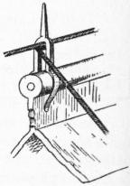
Fig. 4.—Holdfast on Roof.
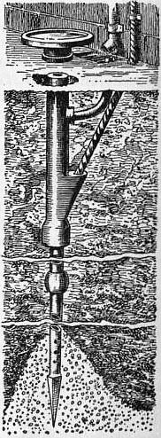
Fig. 5.—Tubular Earth.
Every chimney stack or other prominence should have an air terminal. Conductors should run in the most direct manner from air to earth, and be kept away from the walls by holdfasts (fig. 1), in the manner shown by A (fig. 2); the usual method is seen in B (fig. 2), where the tape follows the contour of the building and causes side flash. A building with a long roof should also be fitted with a horizontal conductor along the ridge, and to this aigrettes (fig. 3) should be attached; a simpler method is to support the cable by holdfasts armed with a spike (fig. 4). Joints must be held together mechanically as well as electrically, and should be protected from the action of the air. At Westminster Abbey the cables are spliced and inserted in a box which is filled with lead run in when molten.
Earth Connexion.—A copper plate not less than 3 sq. ft. in area may be used as an earth connexion if buried in permanently damp ground. Instead of a plate there are advantages in using the tubular earth shown in fig. 5. The cable packed in carbon descends to the bottom of the perforated tube which is driven into the ground, a connexion being made to the nearest rain-water pipe to secure the necessary moisture. No further attention is required. Plate earths should be tested every year. The number of earths depends on the area of the building, but at least two should be provided. Insulators on the conductor are of no advantage, and it is useless to gild or otherwise protect the points of the air-terminals. As heated air offers a good path for lightning (which is the reason why the kitchen-chimney is often selected by the discharge), a number of points should be fixed to high chimneys and there should be at least two conductors to earth. All roof metals, such as finials, flashings, rain-water gutters, ventilating pipes, cowls and stove pipes, should be connected to the system of conductors. The efficiency of the installation depends on the interconnexion of all metallic parts, also on the quality of the earth connexions. In the case of magazines used for explosives, it is questionable whether the usual plan of erecting rods at the sides of the buildings is efficient. The only way to ensure safety is to enclose the magazine in iron; the next best is to arrange the conductors so that they surround it like a bird cage.
Bibliography.—The literature, although extensive, contains so many descriptions of ludicrous devices, that the student, after reading Benjamin Franklin’s Experiments and Observations on Electricity made at Philadelphia (1769), may turn to the Report of the Lightning Rod Conference of December 1881. In the latter work there are abstracts of many valuable papers, especially the reports made to the French Academy, among others by Coulomb, Laplace, Gay-Lussac, Fresnel, Regnault, &c. In 1876 J. Clerk Maxwell read a paper before the British Association in which he brought forward the idea (based on Faraday’s experiments) of protecting a building from the effects of lightning by surrounding it with a sort of cage of rods or stout wire. It was not, however, until the Bath meeting of the British Association in 1888 that the subject was fully discussed by the physical and engineering sections. Sir Oliver Lodge showed the futility of single conductors, and advised the interconnexion of all the metal work on a building to a number of conductors buried in the earth. The action of lightning flashes was also demonstrated by him in lectures delivered before the Society of Arts (1888). The Clerk Maxwell system was adopted to a large extent in Germany, and in July 1901 a sub-committee of the Berlin Electro-technical Association was formed, which published rules. In 1900 a paper entitled “The Protection of Public Buildings from Lightning,” by Killingworth Hedges, led to the formation, by the Royal Institute of British Architects and the Surveyors’ Institution, of the Lightning Research Committee, on which the Royal Society and the Meteorological Society were represented. The Report, edited by Sir Oliver Lodge, Sir John Gavey and Killingworth Hedges (Hon. Sec.), was published in April 1905. An illustrated supplement, compiled by K. Hedges and entitled Modern Lightning Conductors (1905), contains particulars of the independent reports of the German committee, the Dutch Academy of Science, and the Royal Joseph university, Budapest. A description is also given of the author’s modified Clerk Maxwell system, in which the metal work of the roofs of a building form the upper part, the rain-water pipes taking the place of the usual lightning-rods. See also Sir Oliver Lodge, Lightning Conductors (London, 1902).
(K. H.)
LIGHTS, CEREMONIAL USE OF. The ceremonial use of lights in the Christian Church, with which this article is mainly concerned, probably has a double origin: in a very natural symbolism, and in the adaptation of certain pagan and Jewish rites and customs of which the symbolic meaning was Christianized. Light is everywhere Non-Christian religions. the symbol of joy and of life-giving power, as darkness is of death and destruction. Fire, the most mysterious and impressive of the elements, the giver of light and of all the good things of life, is a thing sacred and adorable in primitive religions, and fire-worship still has its place in two at least of the great religions of the world. The Parsis adore fire as the visible expression of Ahura-Mazda, the eternal principle of light and righteousness; the Brahmans worship it as divine and omniscient.1 The Hindu festival of Dewāli (Diyawālī, from diya, light), when temples and houses are illuminated with countless lamps, is held every November to celebrate Lakhshmi, the goddess of prosperity. In the ritual of the Jewish temple fire and light played a conspicuous part. In the Holy of Holies was a “cloud of light” (shekinah), symbolical of the presence of Yahweh, and before it stood the candlestick with six branches, on each of which and on the central stem was a lamp eternally burning; while in the forecourt was an altar on which the sacred fire was never allowed to go out. Similarly the Jewish synagogues have each their eternal lamp; while in the religion of Islam lighted lamps mark things and places specially holy; thus the Ka’ba at Mecca is illuminated by thousands of lamps hanging from the gold and silver rods that connect the columns of the surrounding colonnade.