VOLUME XVI SLICE VI Lightfoot, Joseph to Liquidation (continued 2)
Reading edition
Electric Lighthouse Installations in France.—A list of the thirteen lighthouses on the French coast equipped with electric light installations will be found in table VI. It has been already mentioned that the two lighthouses at La Hève were lit by electric light in 1863 and 1865. These installations were followed within a few years by the establishment of electricity as illuminant at Gris-Nez. In 1882 M. Allard, the then director-general of the French Lighthouse Service, prepared a scheme for the electric lighting of the French littoral by means of 46 lights distributed more or less uniformly along the coast-line. All the apparatus were to be of the same general type, the optics consisting of a fixed belt of 300 mm. focal distance, around the outside of which revolved a system of 24 faces of vertical lenses. These vertical panels condensed the belt of fixed light into beams of 3° amplitude in azimuth, producing flashes of about ¾ sec. duration. To illuminate the near sea the vertical divergence of the lower prisms of the fixed belt was artificially increased. These optics are very similar to that in use at the Souter Point lighthouse, Sunderland. The intensities obtained were 120,000 candles in the case of fixed lights and 900,000 candles with flashing lights. As a result of a nautical inquiry held in 1886, at which date the lights of Dunkerque, Calais, Gris-Nez, La Canche, Baleines and Planier had been lighted, in addition to the old apparatus at La Hève, it was decided to limit the installation of electrical apparatus to important landfall lights—a decision which the Trinity House had already arrived at in the case of the English coast—and to establish new apparatus at six stations only. These were Créac’h d’Ouessant (Ushant), Belle-Île, La Coubre at the mouth of the river Gironde, Barfleur, Île d’Yeu and Penmarc’h. At the same time it was determined to increase the powers of the existing electric lights. The scheme as amended in 1886 was completed in 1902.2
All the electrically lit apparatus, in common with other optics established in France since 1893, have been provided with mercury rotation. The most recent electric lights have been constructed in the form of twin apparatus, two complete and distinct optics being mounted side by side upon the same revolving table and with corresponding faces parallel. It is found that a far larger aggregate candle-power is obtained from two lamps with 16 mm. to 23 mm. diameter carbons and currents of 60 to 120 amperes than with carbons and currents of larger dimensions in conjunction with single optics of greater focal distance. A somewhat similar circumstance led to the choice of the twin form for the two very powerful non-electric apparatus at Île Vierge (figs. 43 and 43A) and Ailly, particulars of which will be seen in table VII.
Several of the de Meritens magneto-electric machines of 5.5 K.W., laid down many years ago at French electric lighthouse stations, are still in use. All these machines have five induction coils, which, upon the installation of the twin optics, were separated into two distinct circuits, each consisting of 2½ coils. This modification has enabled the old plants to be used with success under the altered conditions of lighting entailed by the use of two lamps. The generators adopted in the French service for use at the later stations differ materially from the old type of de Meritens machine. The Phare d’Eckmühl (Penmarc’h) installation serves as a type of the more modern machinery. The dynamos are alternating current two-phase machines, and are installed in duplicate. The two lamps are supplied with current from the same machine, the second dynamo being held in reserve. The speed is 810 to 820 revolutions per minute.
The lamp generally adopted is a combination of the Serrin and Berjot principles, with certain modifications. Clockwork mechanism with a regulating electromagnet moves the rods simultaneously and controls the movements of the carbons so that they are displaced at the same rate as they are consumed. It is usual to employ currents of varying power with carbons of corresponding dimensions according to the atmospheric conditions. In the French service two variations are used in the case of twin apparatus produced by currents of 60 and 120 amperes at 45 volts with carbons 14 mm. and 18 mm. diameter, while in single optic apparatus currents of 25, 50 and 100 amperes are utilized with carbon of 11 mm., 16 mm. and 23 mm. diameter. In England fluted carbons of larger diameter are employed with correspondingly increased current. Alternating currents have given the most successful results in all respects. Attempts to utilize continuous current for lighthouse arc lights have, up to the present, met with little success.
The cost of a first-class electric lighthouse installation of the most recent type in France, including optical apparatus, lantern, dynamos, engines, air compressor, siren, &c., but not buildings, amounts approximately to £5900.
Efficiency of the Electric Light.—In 1883 the lighthouse authorities of Great Britain determined that an exhaustive series of experiments should be carried out at the South Foreland with a view to ascertaining the relative suitability of electricity, gas and oil as lighthouse illuminants. The experiments extended over a period of more than twelve months, and were attended by representatives of the chief lighthouse authorities of the world. The results of the trials tended to show that the rays of oil and gas lights suffered to about equal extent by atmospheric absorption, but that oil had the advantage over gas by reason of its greater economy in cost of maintenance and in initial outlay on installation. The electric light was found to suffer to a much larger extent than either oil or gas light per unit of power by atmospheric absorption, but the infinitely greater total intensity of the beam obtainable by its use, both by reason of the high luminous intensity of the electric arc and its focal compactness, more than outweighed the higher percentage of loss in fog. The final conclusion of the committee on the relative merits of electricity, gas or oil as lighthouse illuminants is given in the following words: “That for ordinary necessities of lighthouse illumination, mineral oil is the most suitable and economical illuminant, and that for salient headlands, important landfalls, and places where a very powerful light is required electricity offers the greater advantages.”
5. Miscellaneous Lighthouse Equipment. Lanterns.—Modern lighthouse lanterns usually consist of a cast iron or steel pedestal, cylindrical in plan, on which is erected the lantern glazing, surmounted by a domed roof and ventilator (fig. 41). Adequate ventilation is of great importance, and is provided by means of ventilators in the pedestal and a large ventilating dome or cowl in the roof. The astragals carrying the glazing are of wrought steel or gun-metal. The astragals are frequently arranged helically or diagonally, thus causing a minimum of obstruction to the light rays in any vertical section and affording greater rigidity to the structure. The glazing is usually ¼-in. thick plate-glass curved to the radius of the lantern. In situations of great exposure the thickness is increased. Lantern roofs are of sheet steel or copper secured to steel or cast-iron rafter frames. In certain instances it is found necessary to erect a grille or network outside the lantern to prevent the numerous sea birds, attracted by the light, from breaking the glazing by impact. Lanterns vary in diameter from 5 ft. to 16 ft. or more, according to the size of the optical apparatus. For first order apparatus a diameter of 12 ft. or 14 ft. is usual.
Lightning Conductors.—The lantern and principal metallic structures in a lighthouse are usually connected to a lightning conductor carried either to a point below low water or terminating in an earth plate embedded in wet ground. Conductors may be of copper tape or copper-wire rope.
Rotating Machinery.—Flashing-light apparatus are rotated by clockwork mechanism actuated by weights. The clocks are fitted with speed governors and electric warning apparatus to indicate variation in speed and when rewinding is required. For occulting apparatus either weight clocks or spring clocks are employed.
Accommodation for Keepers, &c.—At rock and other isolated stations, accommodation for the keepers is usually provided in the towers. In the case of land lighthouses, dwellings are provided in close proximity to the tower. The service or watch room should be situated immediately under the lantern floor. Oil is usually stored in galvanized steel tanks. A force pump is sometimes used for pumping oil from the storage tanks to a service tank in the watch-room or lantern.
6. Unattended Lights and Beacons.—Until recent years no unattended lights were in existence. The introduction of Pintsch’s gas system in the early ’seventies provided a means of illumination for beacons and buoys of which large use has been made. Other illuminants are also in use to a considerable extent.
Unattended Electric Lights.—In 1884 an iron beacon lighted by an incandescent lamp supplied with current from a secondary battery was erected on a tidal rock near Cadiz. A 28-day clock was arranged for eclipsing the light between sunrise and sunset and automatically cutting off the current at intervals to produce an occulting characteristic. Several small dioptric apparatus illuminated with incandescent electric lamps have been made by the firm of Barbier Bénard et Turenne of Paris, and supplied with current from batteries of Daniell cells, with electric clockwork mechanism for occulting the light. These apparatus have been fitted to beacons and buoys, and are generally arranged to automatically switch off the current during the day-time. They run unattended for periods up to two months. Two separate lenses and lamps are usually provided, with lamp changer, only one lamp being in circuit at a time. In the event of failure in the upper lamp of the two the current automatically passes to the lower lamp.
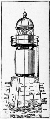
Fig. 46.—Garvel Beacon.
Oil-gas Beacons.—In 1881 a beacon automatically lighted by Pintsch’s compressed oil gas was erected on the river Clyde, and large numbers of these structures have since been installed in all parts of the world. The gas is contained in an iron or steel reservoir placed within the beacon structure, refilled by means of a flexible hose on the occasions of the periodical visits of the tender. The beacons, which remain illuminated for periods up to three months are charged to 7 atmospheres. Many lights are provided with occulting apparatus actuated by the gas passing from the reservoir to the burner automatically cutting off and turning on the supply. The Garvel beacon (1899) on the Clyde is shown in fig. 46. The burner has 7 jets, and the light is occulting. Since 1907 incandescent mantle burners for oil gas have been largely used for beacon illumination, both for fixed and occulting lights.
Acetylene has also been used for the illumination of beacons and other unattended lights.
Lindberg Lights.—In 1881-1882 several beacons lighted automatically by volatile petroleum spirit on the Lindberg-Lyth and Lindberg-Trotter systems were established in Sweden. Many lights of this type have subsequently been placed in different parts of the world. The volatile spirit lamp burns day and night. Occultations are produced by a screen or series of screens rotated round the light by the ascending current of heated air and gases from the lamp acting upon a horizontal fan. The speed of rotation of the fan cannot be accurately adjusted, and the times of occultation therefore are liable to slight variation. The lights run unattended for periods up to twenty-one days.
Benson-Lee Lamps.—An improvement upon the foregoing is the Benson-Lee lamp, in which a similar occulting arrangement is often used, but the illuminant is paraffin consumed in a special burner having carbon-tipped wicks which require no trimming. The flame intensity of the light is greater than that of the burner consuming light spirit. The introduction of paraffin also avoids the danger attending the use of the more volatile spirit. Many of these lights are in use on the Scottish coast. They are also used in other parts of the United Kingdom, and in the United States, Canada and other countries.
Permanent Wick Lights.—About 1891 the French Lighthouse Service introduced petroleum lamps consuming ordinary high-flash lighthouse oil, and burning without attention for periods of several months. The burners are of special construction, provided with a very thick wick which is in the first instance treated in such a manner as to cause the formation of a deposit of carbonized tar on its exposed upper surface. This crust prevents further charring of the wick after ignition, the oil becoming vaporized from the under side of the crust. Many fixed, occulting and flashing lights fitted with these burners are established in France and other countries. In the case of the occulting types a revolving screen is placed around the burner and carried upon a miniature mercury float. The rotation is effected by means of a small Gramme motor on a vertical axis, fitted with a speed governor, and supplied with current from a battery of primary cells. The oil reservoir is placed in the upper part of the lantern and connected with the burner by a tube, to which is fitted a constant level regulator for maintaining the burning level of the oil at a fixed height. In the flashing or revolving light types the arrangement is generally similar, the lenses being revolved upon a mercury float which is rotated by the electric motor. The flashing apparatus established at St Marcouf in 1901 has a beam intensity of 1000 candle-power, and is capable of running unattended for three months. The electric current employed for rotating the apparatus is supplied by four Lalande and Chaperon primary cells, coupled in series, each giving about 0.15 ampere at a voltage of 0.65. The power required to work the apparatus is at the maximum about 0.165 ampere at 0.75 volt, the large surplus of power which is provided for the sake of safety being absorbed by a brake or governor connected with the motor.
Wigham Beacon Lights.—Wigham introduced an oil lamp for beacon and buoy purposes consisting of a vertical container filled with ordinary mineral oil or paraffin, and carrying a roller immediately under the burner case over which a long flat wick passes. One end of the wick is attached to a float which falls in the container as the oil is consumed, automatically drawing a fresh portion of the wick over the roller. The other end of the wick is attached to a free counterweight which serves to keep it stretched. The oil burns from the convex surface of the wick as it passes over the roller, a fresh portion being constantly passed under the action of the flame. The light is capable of burning without attention for thirty days. These lights are also fitted with occulting screens on the Lindberg system. The candle-power of the flame is small.
7. Light-Vessels.—The earliest light-vessel placed in English waters was that at the Nore in 1732. The early light-ships were of small size and carried lanterns of primitive construction and small size suspended from the yard-arms. Modern light-vessels are of steel, wood or composite construction. Steel is now generally employed in new ships. The wood and composite ships are sheathed with Muntz metal. The dimensions of English light-vessels vary. The following may be taken as the usual limits:
Length 80 ft. to 114 ft.
Beam 20 ft. to 24 ft.
Depth moulded 13 ft. to 15 ft. 6 in.
Tonnage 155 to 280.
The larger vessels are employed at outside and exposed stations, the smaller ships being stationed in sheltered positions and in estuaries. The moorings usually consist of 3-ton mushroom anchors and 15⁄8 open link cables. The lanterns in common use are 8 ft. in diameter, circular in form, with glazing 4 ft. in height. They are annular in plan, surrounding the mast of the vessel upon which they are hoisted for illumination, and are lowered to the deck level during the day. Fixed lanterns mounted on hollow steel masts are now being used in many services, and are gradually displacing the older type. The first English light-vessel so equipped was constructed in 1904. Of the 87 light-vessels in British waters, including unattended light-vessels, eleven are in Ireland and six in Scotland. At the present time there are over 750 light-vessels in service throughout the world.
Until about 1895 the illuminating apparatus used in light-vessels was exclusively of catoptric form, usually consisting of 21 in. or 24 in. silvered parabolic reflectors, having 1, 2 or 3-wick mineral oil burners in focus. The reflectors and lamps are hung in gimbals to preserve the horizontal direction of the beams.
The following table gives the intensity of beam obtained by means of a type of reflector in general use:
21-in. Trinity House Parabolic Reflector
Service Intensity of Beam.
Burners 1 wick “Douglass” 2715 candles
” 2 ” (Catoptric) 4004 ”
” 2 ” (Dioptric) 6722 ”
” 3 ” 7528 ”
In revolving flashing lights two or more reflectors are arranged in parallel in each face. Three, four or more faces or groups of reflectors are arranged around the lantern in which they revolve, and are carried upon a turn-table rotated by clockwork. The intensity of the flashing beam is therefore equivalent to the combined intensities of the beams emitted by the several reflectors in each face. The first light-vessel with revolving light was placed at the Swin Middle at the entrance to the Thames in 1837. Group-flashing characteristics can be produced by special arrangements of the reflectors. Dioptric apparatus is now being introduced in many new vessels, the first to be so fitted in England being that stationed at the Swin Middle in 1905, the apparatus of which is gas illuminated and gives a flash of 25,000 candle-power.
Fog signals, when provided on board light-vessels are generally in the form of reed-horns or sirens, worked by compressed air. The compressors are driven from steam or oil engines. The cost of a modern type of English light-vessel, with power-driven compressed air siren, is approximately £16,000.
In the United States service, the more recently constructed vessels have a displacement of 600 tons, each costing £18,000. They are provided with self-propelling power and steam whistle fog signals. The illuminating apparatus is usually in the form of small dioptric lens lanterns suspended at the mast-head—3 or more to each mast, but a few of the ships, built since 1907, are provided with fourth-order revolving dioptric lights in fixed lanterns. There are 53 light-vessels in service on the coasts of the United States with 13 reserve ships.
Electrical Illumination.—An experimental installation of the electric light placed on board a Mersey light-vessel in 1886 by the Mersey Docks and Harbour Board proved unsuccessful. The United States Lighthouse Board in 1892 constructed a light-vessel provided with a powerful electric light, and moored her on the Cornfield Point station in Long Island Sound. This vessel was subsequently placed off Sandy Hook (1894) and transferred to the Ambrose Channel Station in 1907. Five other light-vessels in the United States have since been provided with incandescent electric lights—either with fixed or occulting characteristics—including Nantucket Shoals (1896), Fire Island (1897), Diamond Shoals (1898), Overfalls Shoal (1901) and San Francisco (1902).
Gas Illumination.—In 1896 the French Lighthouse Service completed the construction of a steel light-vessel (Talais), which was ultimately placed at the mouth of the Gironde. The construction of this vessel was the outcome of experiments carried out with a view to produce an efficient light-vessel at moderate cost, lit by a dioptric flashing light with incandescent oil-gas burner. The construction of the Talais was followed by that of a second and larger vessel, the Snouw, on similar lines, having a length of 65 ft. 6 in., beam 20 ft. and a draught of 12 ft., with a displacement of 130 tons. The cost of this vessel complete with optical apparatus and gasholders, with accommodation for three men, was approximately £5000. The vessel was built in 1898-1899.3 A third vessel was constructed in 1901-1902 for the Sandettié Bank on the general lines adopted for the preceding examples of her class, but of the following increased dimensions: length 115 ft.; width at water-line 20 ft. 6 in.; and draught 15 ft., with a displacement of 342 tons (fig. 47). Accommodation is provided for a crew of eight men. The optical apparatus (fig. 48) is dioptric, consisting of 4 panels of 250 mm. focal distance, carried upon a “Cardan” joint below the lens table, and counter-balanced by a heavy pendulum weight. The apparatus is revolved by clockwork and illuminated by compressed oil gas with incandescent mantle. The candle-power of the beam is 35,000. The gas is contained in three reservoirs placed in the hold. The apparatus is contained in a 6-ft. lantern constructed at the head of a tubular mast 2 ft. 6 in. diameter. A powerful siren is provided with steam engine and boiler for working the air compressors. The total cost of the vessel, including fog signal and optical apparatus, was £13,600. A vessel of similar construction to the Talais was placed by the Trinity House in 1905 on the Swin Middle station. The illuminant is oil gas. Gas illuminated light-vessels have also been constructed for the German and Chinese Lighthouse Service.
Unattended Light-vessels.—In 1881 an unattended light-vessel, illuminated with Pintsch’s oil gas, was constructed for the Clyde, and is still in use at the Garvel Point. The light is occulting, and is shown from a dioptric lens fitted at the head of a braced iron lattice tower 30 ft. above water-level. The vessel is of iron, 40 ft. long, 12 ft. beam and 8 ft. deep, and has a storeholder on board containing oil gas under a pressure of six atmospheres capable of maintaining a light for three months. A similar vessel is placed off Calshot Spit in Southampton Water, and several have been constructed for the French and other Lighthouse Services. The French boats are provided with deep main and bilge keels similar to those adopted in the larger gas illuminated vessels. In 1901 a light-vessel 60 ft. in length was placed off the Otter Rock on the west coast of Scotland; it is constructed of steel, 24 ft. beam, 12 ft. deep and draws 9 ft. of water (fig. 49). The focal plane is elevated 25 ft. above the water-line, and the lantern is 6 ft. in diameter. The optical apparatus is of 500 mm. focal distance and hung in gimbals with a pendulum balance and “Cardan” joint as in the Sandettié light-vessel. The illuminant is oil gas, with an occulting characteristic. The storeholder contains 10,500 cub. ft. of gas at eight atmospheres, sufficient to supply the light for ninety days and nights. A bell is provided, struck by clappers moved by the roll of the vessel. The cost of the vessel complete was £2979. The Northern Lighthouse Commissioners have four similar vessels in service, and others have been stationed in the Hugli estuary, at Bombay, off the Chinese coasts and elsewhere. In 1909 an unattended gas illuminated light-vessel provided with a dioptric flashing apparatus was placed at the Lune Deep in Morecambe Bay. It is also fitted with a fog bell struck automatically by a gas operated mechanism.
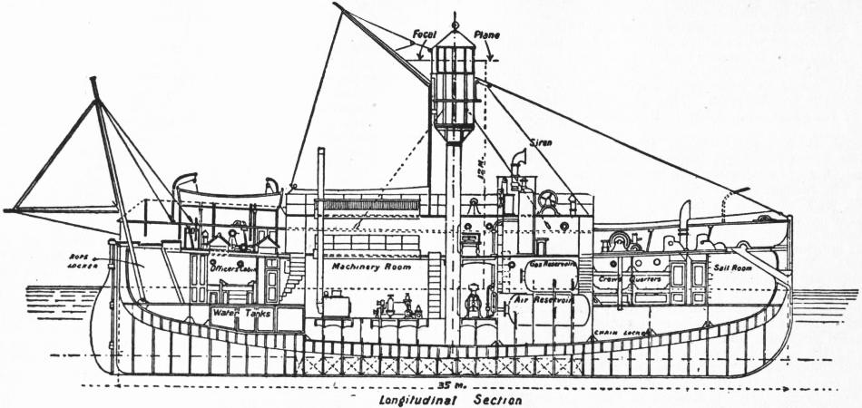
Fig. 47.—Sandettié Lightship.
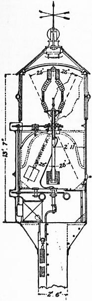
Fig. 48.—Lantern of Sandettié Lightship.
Electrical Communication of Light-vessels with the Shore.—Experiments were instituted in 1886 at the Sunk light-vessel off the Essex coast with the view to maintaining telephonic communication with the shore by means of a submarine cable 9 m. in length. Great difficulties were experienced in maintaining communication during stormy weather, breakages in the cable being frequent. These difficulties were subsequently partially overcome by the employment of larger vessels and special moorings. Wireless telegraphic installations have now (1910) superseded the cable communications with light-vessels in English waters except in four cases. Seven light-vessels, including the four off the Goodwin Sands, are now fitted for wireless electrical communication with the shore.
In addition many pile lighthouses and isolated rock and island stations have been placed in electrical communication with the shore by means of cables or wireless telegraphy. The Fastnet lighthouse was, in 1894, electrically connected with the shore by means of a non-continuous cable, it being found impossible to maintain a continuous cable in shallow water near the rock owing to the heavy wash of the sea. A copper conductor, carried down from the tower to below low-water mark, was separated from the cable proper, laid on the bed of the sea in a depth of 13 fathoms, by a distance of about 100 ft. The lighthouse was similarly connected to earth on the opposite side of the rock. The conductor terminated in a large copper plate, and to the cable end was attached a copper mushroom. Weak currents were induced in the lighthouse conductor by the main current in the cable, and messages received in the tower by the help of electrical relays. On the completion of the new tower on the Fastnet Rock in 1906 this installation was superseded by a wireless telegraphic installation.
8. Distribution and Distinction of Lights, &c.—Methods of Distinction.—The following are the various light characteristics which may be exhibited to the mariner:—
Fixed.—Showing a continuous or steady light. Seldom used in modern lighthouses and generally restricted to small port or harbour lights. A fixed light is liable to be confused with lights of shipping or other shore lights.
Flashing.4—Showing a single flash, the duration of darkness always being greater than that of light. This characteristic or that immediately following is generally adopted for important lights. The French authorities have given the name Feux-Eclair to flashing lights of short duration.
Group-Flashing.—Showing groups of two or more flashes in quick succession (not necessarily of the same colour) separated by eclipses with a larger interval of darkness between the groups.
Fixed and Flashing.—Fixed light varied by a single white or coloured flash, which may be preceded and followed by a short eclipse. This type of light, in consequence of the unequal intensities of the beams, is unreliable, and examples are now seldom installed although many are still in service.
Fixed and Group-Flashing.—Similar to the preceding and open to the same objections.
Revolving.—This term is still retained in the “Lists of Lights” issued by the Admiralty and some other authorities to denote a light gradually increasing to full effect, then decreasing to eclipse. At short distances and in clear weather a faint continuous light may be observed. There is no essential difference between revolving and flashing lights, the distinction being merely due to the speed of rotation, and the term might well be abandoned as in the United States lighthouse list.
Occulting.—A continuous light with, at regular intervals, one sudden and total eclipse, the duration of light always being equal to or greater than that of darkness. This characteristic is usually exhibited by fixed dioptric apparatus fitted with some form of occulting mechanism. Many lights formerly of fixed characteristic have been converted to occulting.
Group Occulting.—A continuous light with, at regular intervals, groups of two or more sudden and total eclipses.
Alternating.—Lights of different colours (generally red and white) alternately without any intervening eclipse. This characteristic is not to be recommended for reasons which have already been referred to. Many of the permanent and unwatched lights on the coasts of Norway and Sweden are of this description.
Colour.—The colours usually adopted for lights are white, red and green. White is to be preferred whenever possible, owing to the great absorption of light by the use of red or green glass screens.
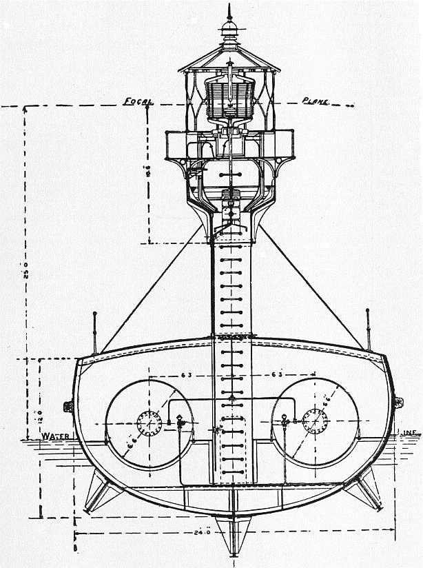
Fig. 49.—Otter Rock Light-vessel.
Sectors.—Coloured lights are often requisite to distinguish cuts or sectors, and should be shown from fixed or occulting light apparatus and not from flashing apparatus. In marking the passage through a channel, or between sandbanks or other dangers, coloured light sectors are arranged to cover the dangers, white light being shown over the fairway with sufficient margin of safety between the edges of the coloured sectors next the fairway and the dangers.
Choice of Characteristic and Description of Apparatus.—In determining the choice of characteristic for a light due regard must be paid to existing lights in the vicinity. No light should be placed on a coast line having a characteristic the same as, or similar to, another in its neighbourhood unless one or more lights of dissimilar characteristic, and at least as high power and range, intervene. In the case of “landfall lights” the characteristic should differ from any other within a range of 100 m. In narrow seas the distance between lights of similar characteristic may be less. Landfall lights are, in a sense, the most important of all and the most powerful apparatus available should be installed at such stations. The distinctive characteristic of a light should be such that it may be readily determined by a mariner without the necessity of accurately timing the period or duration of flashes. For landfall and other important coast stations flashing dioptric apparatus of the first order (920 mm. focal distance) with powerful burners are required. In countries where the atmosphere is generally clear and fogs are less prevalent than on the coasts of the United Kingdom, second or third order lights suffice for landfalls having regard to the high intensities available by the use of improved illuminants. Secondary coast lights may be of second, third or fourth order of flashing character, and important harbour lights of third or fourth order. Less important harbours and places where considerable range is not required, as in estuaries and narrow seas, may be lighted by flashing lights of fourth order or smaller size. Where sectors are requisite, occulting apparatus should be adopted for the main light; or subsidiary lights, fixed or occulting, may be exhibited from the same tower as the main light but at a lower level. In such cases the vertical distance between the high and the low light must be sufficient to avoid commingling of the two beams at any range at which both lights are visible. Such commingling or blending is due to atmospheric aberration.
Range of Lights.—The range of a light depends first on its elevation above sea-level and secondly on its intensity. Most important lights are of sufficient power to render them visible at the full geographical range in clear weather. On the other hand there are many harbour and other lights which do not meet this condition.
The distances given in lists of lights from which lights are visible—except in the cases of lights of low power for the reason given above—are usually calculated in nautical miles as seen from a height of 15 ft. above sea-level, the elevation of the lights being taken as above high water. Under certain atmospheric conditions, and especially with the more powerful lights, the glare of the light may be visible considerably beyond the calculated range.
Table III.—Distances at which Objects can be seen at Sea, according to their Respective Elevations and the Elevation of the Eye of the Observer. (A. Stevenson.)
Heights in Feet. Distances in Geographical or Nautical Miles. Heights in Feet. Distances in Geographical or Nautical Miles.
5 2.565 110 12.03
10 3.628 120 12.56
15 4.443 130 13.08
20 5.130 140 13.57
25 5.736 150 14.02
30 6.283 200 16.22
35 6.787 250 18.14
40 7.255 300 19.87
45 7.696 350 21.46
50 8.112 400 22.94
55 8.509 450 24.33
60 8.886 500 25.65
65 9.249 550 26.90
70 9.598 600 28.10
75 9.935 650 29.25
80 10.26 700 30.28
85 10.57 800 32.45
90 10.88 900 34.54
95 11.18 1000 36.28
100 11.47
Example: A tower 200 ft. high will be visible 20.66 nautical miles to an observer, whose eye is elevated 15 ft. above the water; thus, from the table:
15 ft. elevation, distance visible 4.44 nautical miles
200 ” ” 16.22 ”
——
20.66 ”

Fig. 50.—Spar Gas Buoy.
Elevation of Lights.—The elevation of the light above sea-level need not, in the case of landfall lights, exceed 200 ft., which is sufficient to give a range of over 20 nautical miles. One hundred and fifty feet is usually sufficient for coast lights. Lights placed on high headlands are liable to be enveloped in banks of fog at times when at a lower level the atmosphere is comparatively clear (e.g. Beachy Head). No definite rule can, however, be laid down, and local circumstances, such as configuration of the coast line, must be taken into consideration in every case.
Choice of Site.—“Landfall” stations should receive first consideration and the choice of location for such a light ought never to be made subservient to the lighting of the approaches to a port. Subsidiary lights are available for the latter purpose. Lights installed to guard shoals, reefs or other dangers should, when practicable, be placed seaward of the danger itself, as it is desirable that seamen should be able to “make” the light with confidence. Sectors marking dangers seaward of the light should not be employed except when the danger is in the near vicinity of the light. Outlying dangers require marking by a light placed on the danger or by a floating light in its vicinity.
9. Illuminated Buoys.—Gas Buoys. Pintsch’s oil gas has been in use for the illumination of buoys since 1878. In 1883 an automatic occulter was perfected, worked by the gas passing from the reservoir to the burner. The lights placed on these buoys burn continuously for three or more months. The buoys and lanterns are made in various forms and sizes. The spar buoy (fig. 50) may be adopted for situations where strong tides or currents prevail. Oil gas lights are frequently fitted to Courtenay whistling (fig. 51) and bell buoys.
In the ordinary type of gas buoy lantern the burner employed is of the multiple-jet, Argand ring, or incandescent type. Incandescent mantles have been applied to buoy lights in France with successful results. Since 1906, and more recently the same system of illumination has been adopted in England and other countries. The lenses employed are of cylindrical dioptric fixed-light form, usually 100 mm. to 300 mm. diameter. Some of the largest types of gas-buoy in use on the French coast have an elevation from water level to the focal plane of over 26 ft. with a beam intensity of more than 1000 candles. A large gas-buoy with an elevation of 34 ft. to the focal plane was placed at the entrance to the Gironde in 1907. It has an incandescent burner and exhibits a light of over 1500 candles. Oil gas forms the most trustworthy and efficient illuminant for buoy purposes yet introduced, and the system has been largely adopted by lighthouse and harbour authorities.
There are now over 2000 buoys fitted with oil gas apparatus, in addition to 600 beacons, light-vessels and boats.
Electric Lit Buoys.—Buoys have been fitted with electric light, both fixed and occulting. Six electrically lit spar-buoys were laid down in the Gedney channel, New York lower bay, in 1888. These were illuminated by 100 candle-power Swan lamps with continuous current supplied by cable from a power station on shore. The wear and tear of the cables caused considerable trouble and expense. In 1895 alternating current was introduced. The installation was superseded by gas lit buoys in 1904.
Acetylene and Oil Lighted Buoys.—Acetylene has been extensively employed for the lighting of buoys in Canada and in the United States; to a less extent it has also been adopted in other countries. Both the low pressure system, by which the acetylene gas is produced by an automatic generator, and the so-called high pressure system in which purified acetylene is held in solution in a high pressure gasholder filled with asbestos composition saturated with acetone, have been employed for illuminating buoys and beacons. Wigham oil lamps are also used to a limited extent for buoy lighting.
Bell Buoys.—One form of clapper actuated by the roll of the buoy (shown in fig. 52) consists of a hardened steel ball placed in a horizontal phosphor-bronze cylinder provided with rubber buffers. Three of these cylinders are arranged around the mouth of the fixed bell, which is struck by the balls rolling backwards and forwards as the buoy moves. Another form of bell mechanism consists of a fixed bell with three or more suspended clappers placed externally which strike the bell when the buoy rolls.
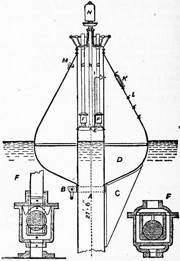
Fig. 51.—Courtenay’s Automatic Whistling Buoy.
A, Cylinder, 27 ft. 6 in. long. B, Mooring shackle. C, Rudder. D, Buoy. E, Diaphragm. F, Ball valves. G, Air inlet tubes. H, Air (compressed outlet tube to whistle). I, Compressed air inlet to buoy. K, Manhole. L, Steps. N, Whistle.
10. Fog Signals.—The introduction of coast fog signals is of comparatively recent date. They were, until the middle of the 19th century, practically unknown except so far as a few isolated bells and guns were concerned. The increasing demands of navigation, and the application of steam power to the propulsion of ships resulting in an increase of their speed, drew attention to the necessity of providing suitable signals as aids to navigation during fog and mist. In times of fog the mariner can expect no certain assistance from even the most efficient system of coast lighting, since the beams of light from the most powerful electric lighthouse are frequently entirely dispersed and absorbed by the particles of moisture, forming a sea fog of even moderate density, at a distance of less than a ¼ m. from the shore. The careful experiments and scientific research which have been devoted to the subject of coast fog-signalling have produced much that is useful and valuable to the mariner, but unfortunately the practical results so far have not been so satisfactory as might be desired, owing to (1) the very short range of the most powerful signals yet produced under certain unfavourable acoustic conditions of the atmosphere, (2) the difficulty experienced by the mariner in judging at any time how far the atmospheric conditions are against him in listening for the expected signal, and (3) the difficulty in locating the position of a sound signal by phonic observations.
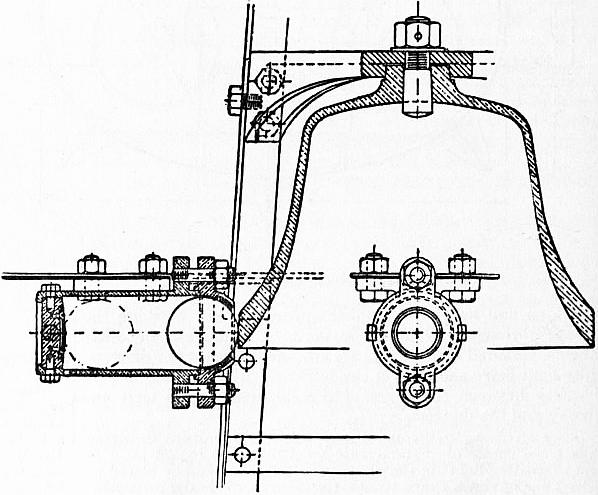
Fig. 52.—Buoy Bell.
Bells and Gongs are the oldest and, generally speaking, the least efficient forms of fog signals. Under very favourable acoustic conditions the sounds are audible at considerable ranges. On the other hand, 2-ton bells have been inaudible at distances of a few hundred yards. The 1893 United States trials showed that a bell weighing 4000 ℔ struck by a 450 ℔ hammer was heard at a distance of 14 m. across a gentle breeze and at over 9 m. against a 10-knot breeze. Bells are frequently used for beacon and buoy signals, and in some cases at isolated rock and other stations where there is insufficient accommodation for sirens and horns, but their use is being gradually discontinued in this country for situations where a powerful signal is required. Gongs, usually of Chinese manufacture, were formerly in use on board English light-ships and are still used to some extent abroad. These are being superseded by more powerful sound instruments.
Explosive Signals.—Guns were long used at many lighthouse and light-vessel stations in England, and are still in use in Ireland and at some foreign stations. These are being gradually displaced by other explosive or compressed air signals. No explosive signals are in use on the coasts of the United States. In 1878 sound rockets charged with gun-cotton were first used at Flamborough Head and were afterwards supplied to many other stations.5 The nitrated gun-cotton or tonite signals now in general use are made up in 4 oz. charges. These are hung at the end of an iron jib or pole attached to the lighthouse lantern or other structure, and fired by means of a detonator and electric battery. The discharge may take place within 12 ft. of a structure without danger. The cartridges are stored for a considerable period without deterioration and with safety. This form of signal is now very generally adopted for rock and other stations in Great Britain, Canada, Newfoundland, northern Europe and other parts of the world. An example will be noticed in the illustration of the Bishop Rock lighthouse, attached to the lantern (fig. 13). Automatic hoisting and firing appliances are also in use.
Whistles.—Whistles, whether sounded by air or steam, are not used in Great Britain, except in two instances of harbour signals under local control. It has been objected that their sound has too great a resemblance to steamers’ whistles, and they are wasteful of power. In the United States and Canada they are largely used. The whistle usually employed consists of a metallic dome or bell against which the high-pressure steam impinges. Rapid vibrations are set up both in the metal of the bell and in the internal air, producing a shrill note. The Courtenay buoy whistle, already referred to, is an American invention and finds favour in the United States, France, Germany and elsewhere.
Reed-Horns.—These instruments in their original form were the invention of C. L. Daboll, an experimental horn of his manufacture being tried in 1851 by the United States Lighthouse Board. In 1862 the Trinity House adopted the instrument for seven land and light-vessel stations. For compressing air for the reed-horns as well as sirens, caloric, steam, gas and oil engines have been variously used, according to local circumstances. The reed-horn was improved by Professor Holmes, and many examples from his designs are now in use in England and America. At the Trinity House experiments with fog signals at St Catherine’s (1901) several types of reed-horn were experimented with. The Trinity House service horn uses air at 15 ℔ pressure with a consumption of .67 cub. ft. per second and 397 vibrations. A small manual horn of the Trinity House type consumes .67 cub. ft. of air at 5 ℔ pressure. The trumpets of the latter are of brass.
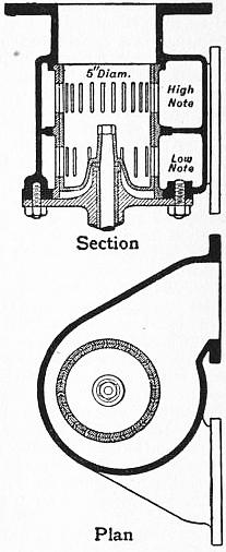
Fig. 53.—St Catherine’s Double-noted Siren.
Sirens.—The most powerful and efficient of all compressed air fog signals is the siren. The principle of this instrument may be briefly explained as follows:—It is well known that if the tympanic membrane is struck periodically and with sufficient rapidity by air impulses or waves a musical sound is produced. Robinson was the first to construct an instrument by which successive puffs of air under pressure were ejected from the mouth of a pipe. He obtained this effect by using a stop-cock revolving at high speed in such a manner that 720 pulsations per second were produced by the intermittent escape of air through the valves or ports, a smooth musical note being given. Cagniard de la Tour first gave such an instrument the name of siren, and constructed it in the form of an air chamber with perforated lid or cover, the perforations being successively closed and opened by means of a similarly perforated disk fitted to the cover and revolving at high speed. The perforations being cut at an angle, the disk was self-rotated by the oblique pressure of the air in escaping through the slots. H. W. Dove and Helmholtz introduced many improvements, and Brown of New York patented, about 1870, a steam siren with two disks having radial perforations or slots. The cylindrical form of the siren now generally adopted is due to Slight, who used two concentric cylinders, one revolving within the other, the sides being perforated with vertical slots. To him is also due the centrifugal governor largely used to regulate the speed of rotation of the siren. Over the siren mouth is placed a conical trumpet to collect and direct the sound in the desired direction. In the English service these trumpets are generally of considerable length and placed vertically, with bent top and bell mouth. Those at St Catherine’s are of cast-iron with copper bell mouth, and have a total axial length of 22 ft. They are 5 in. in diameter at the siren mouth, the bell mouth being 6 ft. in diameter. At St Catherine’s the sirens are two in number, 5 in. in diameter, being sounded simultaneously and in unison (fig. 53). Each siren is provided with ports for producing a high note as well as a low note, the two notes being sounded in quick succession once every minute. The trumpet mouths are separated by an angle of 120° between their axes. This double form has been adopted in certain instances where the angle desired to be covered by the sound is comparatively wide. In Scotland the cylindrical form is used generally, either automatically or motor driven. By the latter means the admission of air to the siren can be delayed until the cylinder is rotating at full speed, and a much sharper sound is produced than in the case of the automatic type. The Scottish trumpets are frequently constructed so that the greater portion of the length is horizontal. The Girdleness trumpet has an axial length of 16 ft., 11 ft. 6 in. being horizontal. The trumpet is capable of being rotated through an angle as well as dipped below the horizon. It is of cast-iron, no bell mouth is used, and the conical mouth is 4 ft. in diameter. In France the sirens are cylindrical and very similar to the English self-driven type. The trumpets have a short axial length, 4 ft. 6 in., and are of brass, with bent bell mouth. The Trinity House has in recent years reintroduced the use of disk sirens, with which experiments are still being carried out both in the United Kingdom and abroad. For light-vessels and rock stations where it is desired to distribute the sound equally in all directions the mushroom-head trumpet is occasionally used. The Casquets trumpet of this type is 22 ft. in length, of cast-iron, with a mushroom top 6 ft. in diameter. In cases where neither the mushroom trumpet nor the twin siren is used the single bent trumpet is arranged to rotate through a considerable angle. Table IV. gives particulars of a few typical sirens of the most recent form.
Table IV.
Station. Description. Vibrations per sec. Sounding Pressure in lb per sq. in. Cub. ft. of air used per sec. of blast reduced to atmospheric pressure. Remarks.
High. Low. High. Low.
St Catherine’s (Trinity House) Two 5-in. cylindrical, automatically driven sirens 295 182 25 32 16 The air consumption is for 2 sirens.
Girdleness (N.L.C) 7-in. cylindrical siren, motor driven 234 100 30 130 26
Casquets (Trinity House) 7-in. disk siren, motor driven .. 98 25 .. 36
French pattern siren 6-in. cylindrical siren, automatically driven 326 .. 28 14 .. A uniform note of 326 vibrations per sec. has now been adopted generally in France.
Since the first trial of the siren at the South Foreland in 1873 a very large number of these instruments have been established both at lighthouse stations and on board light-vessels. In all cases in Great Britain and France they are now supplied with air compressed by steam or other mechanical power. In the United States and some other countries steam, as well as compressed air, sirens are in use.
Diaphones.—The diaphone is a modification of the siren, which has been largely used in Canada since 1903 in place of the siren. It is claimed that the instrument emits a note of more constant pitch than does the siren. The distinction between the two instruments is that in the siren a revolving drum or disk alternately opens and closes elongated air apertures, while in the diaphone a piston pulsating at high velocity serves to alternately cover and uncover air slots in a cylinder.
The St Catherine’s Experiments.—Extensive trials were carried out during 1901 by the Trinity House at St Catherine’s lighthouse, Isle of Wight, with several types of sirens and reed-horns. Experiments were also made with different pattern of trumpets, including forms having elliptical sections, the long axis being placed vertically. The conclusions of the committee may be briefly summarized as follows: (1) When a large arc requires to be guarded two fixed trumpets suitably placed are more effective than one large trumpet capable of being rotated. (2) When the arc to be guarded is larger than that effectively covered by two trumpets, the mushroom-head trumpet is a satisfactory instrument for the purpose. (3) A siren rotated by a separate motor yields better results than when self-driven. (4) No advantage commensurate with the additional power required is obtained by the use of air at a higher pressure than 25 ℔ per sq. in. (5) The number of vibrations per second produced by the siren or reed should be in unison with the proper note of the associated trumpet. (6) When two notes of different pitch are employed the difference between these should, if possible, be an octave. (7) For calm weather a low note is more suitable than a high note, but when sounding against the wind and with a rough and noisy sea a high note has the greater range. (8) From causes which cannot be determined at the time or predicted beforehand, areas sometimes exist in which the sounds of fog signals may be greatly enfeebled or even lost altogether. This effect was more frequently observed during comparatively calm weather and at no great distance from the signal station. (It has often been observed that the sound of a signal may be entirely lost within a short distance of the source, while heard distinctly at a greater distance and at the same time.) (9) The siren was the most effective signal experimented with; the reed-horn, although inferior in power, is suitable for situations of secondary importance. (No explosive signals were under trial during the experiments.) (10) A fog signal, owing to the uncertainty attending its audibility, must be regarded only as an auxiliary aid to navigation which cannot at all times be relied upon.
Submarine Bell Signals.—As early as 1841 J. D. Colladon conducted experiments on the lake of Geneva to test the suitability of water as a medium for transmission of sound signals and was able to convey distinctly audible sounds through water for a distance of over 21 m., but it was not until 1904 that any successful practical application of this means of signalling was made in connexion with light-vessels. There are at present (1910) over 120 submarine bells in service, principally in connexion with light-vessels, off the coasts of the United Kingdom, United States, Canada, Germany, France and other countries. These bells are struck by clappers actuated by pneumatic or electrical mechanism. Other submerged bells have been fitted to buoys and beacon structures, or placed on the sea bed; in the former case the bell is actuated by the motion of the buoy and in others by electric current, transmitted by cable from the shore. In some cases, when submarine bells are associated with gas buoys or beacons, the compressed gas is employed to actuate the bell striking mechanism. To take full advantage of the signals thus provided it is necessary for ships approaching them to be fitted with special receiving mechanism of telephonic character installed below the water line and in contact with the hull plating. The signals are audible by the aid of ear pieces similar to ordinary telephone receivers. Not only can the bell signals be heard at considerable distances—frequently over 10 m.—and in all conditions of weather, but the direction of the bell in reference to the moving ship can be determined within narrow limits. The system is likely to be widely extended and many merchant vessels and war ships have been fitted with signal receiving mechanism.
The following table (V.) gives the total numbers of fog signals of each class in use on the 1st of January 1910 in certain countries.
Table V.
Sirens. Diaphone. Horns, Trumpets, &c. Whistles. Explosive Signals (tonite, &c.). Guns. Bells. Gongs. Submarine Bells. Totals.
Power. Manual.
England and Channel Islands 44 .. 27 31 2 15 .. 48 10 16 193
Scotland and Isle of Man 35 .. 6 2 .. 5 .. 16 3 .. 67
Ireland 12 .. 2 6 .. 11 3 11 .. 3 48
France 12 .. 7 1 .. 1 .. 25 .. 2 48
United States (excluding inland
lakes and rivers) 43 .. 35 15 59 .. .. 218 1 36 407
British North America (excluding
inland lakes and rivers) 6 66 5 79 16 8 .. 24 .. 11 215
When two kinds of signal are employed at any one station, one being subsidiary, the latter is omitted from the enumeration. Buoy and unattended beacon bells and whistles are also omitted, but local port and harbour signals not under the immediate jurisdiction of the various lighthouse boards are included, more especially in Great Britain.
11. Lighthouse Administration. The principal countries of the world possess organized and central authorities responsible for the installation and maintenance of coast lights and fog signals, buoys and beacons.
United Kingdom.—In England the corporation of Trinity House, or according to its original charter, “The Master Wardens, and Assistants of the Guild Fraternity or Brotherhood of the most glorious and undivided Trinity and of St Clement, in the Parish of Deptford Strond, in the county of Kent,” existed in the reign of Henry VII. as a religious house with certain duties connected with pilotage, and was incorporated during the reign of Henry VIII. In 1565 it was given certain rights to maintain beacons, &c., but not until 1680 did it own any lighthouses. Since that date it has gradually purchased most of the ancient privately owned lighthouses and has erected many new ones. The act of 1836 gave the corporation control of English coast lights with certain supervisory powers over the numerous local lighting authorities, including the Irish and Scottish Boards. The corporation now consists of a Master, Deputy-master, and 22 Elder Brethren (10 of whom are honorary), together with an unlimited number of Younger Brethren, who, however, perform no executive duties. In Scotland and the Isle of Man the lights are under the control of the Commissioners of Northern Lighthouses constituted in 1786 and incorporated in 1798. The lighting of the Irish coast is in the hands of the Commissioners of Irish Lights formed in 1867 in succession to the old Dublin Ballast Board. The principal local light boards in the United Kingdom are the Mersey Docks and Harbour Board, and the Clyde Lighthouse Trustees. The three general lighthouse boards of the United Kingdom, by the provision of the Mercantile Marine Act of 1854, are subordinate to the Board of Trade, which controls all finances.
On the 1st of January 1910 the lights, fog signals and submarine bells in service under the control of the several authorities in the United Kingdom were as follows:
Light- houses. Light- vessels. Fog Signals. Submarine Bells.
Trinity House 116 51 97 12
Northern Lighthouse Commissioners 138 5 44 ..
Irish Lights Commissioners 93 11 35 3
Mersey Docks and Harbour Board 16 6 13 2
Admiralty 31 2 6 ..
Clyde Lighthouse Trustees 14 1 5 ..
Other local lighting authorities 809 11 89 2
Totals 1217 87 289 19
Some small harbour and river lights of subsidiary character are not included in the above total.
United States.—The United States Lighthouse Board was constituted by act of Congress in 1852. The Secretary of Commerce and Labor is the ex-officio president. The board consists of two officers of the navy, two engineer officers of the army, and two civilian scientific members, with two secretaries, one a naval officer, the other an officer of engineers in the army. The members are appointed by the president of the United States. The coast-line of the states, with the lakes and rivers and Porto Rico, is divided into 16 executive districts for purposes of administration.
The following table shows the distribution of lighthouses, light-vessels, &c., maintained by the lighthouse board in the United States in June 1909. In addition there are a few small lights and buoys privately maintained.
Lighthouses and beacon lights 1333
Light-vessels in position 53
Light-vessels for relief 13
Gas lighted buoys in position 94
Fog signals operated by steam or oil engines 228
Fog signals operated by clockwork, &c. 205
Submarine signals 43
Post lights 2333
Day or unlighted beacons 1157
Bell buoys in position 169
Whistling buoys in position 94
Other buoys 5760
Steam tenders 51
Constructional Staff 318
Light keepers; and light attendants 3137
Officers and crews of light-vessels and tenders 1693
France.—The lighthouse board of France is known as the Commission des Phares, dating from 1792 and remodelled in 1811, and is under the direction of the minister of public works. It consists of four engineers, two naval officers and one member of the Institute, one inspector-general of marine engineers, and one hydrographic engineer. The chief executive officers are an Inspecteur Général des Ponts et Chaussées, who is director of the board, and another engineer of the same corps, who is engineer-in-chief and secretary. The board has control of about 750 lights, including those of Corsica, Algeria, &c. A similar system has been established in Spain.
Table VI.—Electric Lighthouse Apparatus.
Name. Characteristic. Period. Duration of Flash. Candle-power (Service Intensity). Focal Distance of Lens. Ratio of Angular Breadth of Panel to Whole Circle. Current. Voltage. Carbons. Electric Generators. Lamps. Engins. Elevation above High Water. Year Established. Remarks.
Secs. Secs. Standard Candles. mm. Amps. mm. Feet.
United Kingdom—
Souter Point (Durham) Single flash 30 5 Candle-power not officially determined. 500 1 : 8 .. 40 17 Holmes machines, alternating (400 revs.) Serrin Steam 150 1871 Fixed light apparatus, with revolving vertical condensing lenses in eight panels.
South Foreland (Kent) Single flash 2.5 .35 700 1 : 16 .. 40 26 do. Serrin Steam 374 1904 Lens elements only; 97° vertical angle. (This apparatus was in use at St Catherine’s, 1888 to 1904, and replaced the two fixed electric lights established in 1872.)
Lizard (Cornwall) Single flash 3 .13 700 1 : 4 145 for 50 mm. carbons 40 50 and 60 fluted De Meritens alternators (600 revs.) Modified Berjot-Serrin Oil engines 230 1903 Mercury rotation; vertical angle, 139°. Replaced the two fixed electric lights erected in 1878.
St Catherine’s (Isle of Wight) Single flash 5 .21 700 1 : 4 145 for 50 mm. carbons 40 50 and 60 fluted do. do. 2 Steam, each 50 h.p. 136 1904 Mercury rotation; vertical angle, 139°.
Isle of May (Firth of Forth) 4 flash 30 .4 700 (Fixed apparatus) 1 : 8 220 40 40 do. Berjot-Serrin Steam 240 1886 Fixed light apparatus, with revolving vertical condensing lenses.
France—
Dunkerque (Strait of Dover) 2 flash 10 .2 to .4 3,500,000 to 6,500,000 300 1 : 12 30 and 60 45 14 and 18 2 De Meritens alternators, each of 5.5 k.w. (550 revs.) Improved Serrin 2 Semi-portable steam, each 30 i.h.p. 193 1902 Twelve panels in groups of two. (This apparatus was in use at Barfleur, 1893 to 1902.)
Calais (Strait of Dover) [Les Baleines (1882) similar] 4 flash 15 .75 900,000 300 1 : 24 60 45 18 do. French Service pattern (1902) do. 190 1883 Fixed light apparatus, with revolving vertical condensing prisms.
Cap Gris-nez (Strait of Dover) Single flash 5 .10 to .14 15,000,000 to 30,000,000 300 1 : 4 60 to 120 45 18 and 28 do. do. Steam 233 1899 Twin optic, mercury rotation. (This light superseded a triple-flashing electric light, with intermediate red flash, of the Calais type, established in 1885. The first installation of the electric light at this station was in 1869.)
La Canche (Strait of Dover) 2 flash 10 .10 to .14 15,000,000 to 30,000,000 300 1 : 4 30 to 60 45 14 and 18 do. do. do. 174 1900 Twin optic, mercury rotation. (This light superseded a fixed electric light established in 1884.)
Cap de la Hève (Havre, English Channel) [Île d’Yeu in the Bay of Biscay (1895) similar] Single flash 5 .10 to .14 10,000,000 to 20,000,000 300 1 : 4 60 to 120 45 18 and 28 De Meritens alternators (550 revs.) Improved Serrin do. 397 1893 Mercury rotation. (The first installation of electric light at this lighthouse was in 1863.)
Créac’h d’Ouessant (Ushant) [Barfleur (English Channel) 1903, La Coubre (Bay of Biscay) 1905, and Belle Île (Bay of Biscay) 1903, similar] 2 flash 10 .10 to .14 15,000,000 to 30,000,000 300 1 : 4 60 to 120 45 18 and 28 2 De Meritens alternators, each of 5.5 k.w. (550 revs.) French Service pattern (1902) do. 225 1901 Twin optic, mercury rotation. (This light superseded a double-flashing electric light, similar to that now at Dunkerque, established in 1888.)
Penmarc’h (Phare d’Eckmühl) (Finistère) Single flash 5 .10 to .14 15,000,000 to 30,000,000 300 1 : 4 30 and 60 45 14 and 18 Two-phase Labour alternators (810 to 820 revs.) do. do. 197 1897 Twin optic, mercury rotation.
Planier (near Marseilles) Single flash 5 .10 to .14 15,000,000 to 30,000,000 300 1 : 4 30 to 60 45 14 to 18 De Meritens alternators (550 revs.) do. do. 207 1902 Twin optic, mercury rotation. (This light superseded an electric light established in 1881, showing a group of three white flashes separated by one red flash of the Calais type.)
Italy—
Tino (Gulf of Spezia) 3 flash 30 1.25 Undetermined. 700 1 : 24 50 110 200 50 15 25 35 do. (830 revs.) Berjot-Serrin do. 384 1885 Eight panels of three lenses each, no mirror.
America—
Navesink (Entrance to New York Bay) Single flash 5 .08 About 60,000,000 700 Nearly 1 : 2 Max. 100 50 23 Alternating dynamos (800 revs.) Modified Serrin (Ciolina) Oil, each 25 h.p. 246 1898 Mercury rotation. Bivalve of 165°.
Australia—
Macquarie (Sydney, N.S.W.) Single flash 60 8 5,000,000 920 1 : 16 55 110 50 15 25 De Meritens alternators (600 revs.) Serrin Gas 345 1883 16-panel revolving apparatus, with 180° fixed mirror.
Table VII.—Typical Non-Electric Lighthouse Apparatus.
Name. Locality. Characteristic. Period. Duration of Flashes. Candle-Power in Standard Candles (Service Intensity). Focal Distance of Lens. Ratio of Angular Breadth of Panel to Whole Circle. Illuminant. Burner. Service Candle-power of Burner. Height above High Water. Year Established.* Remarks.
Secs. Secs. mm. Feet.
Casquets Channel Islands 3 flash 30 1.5 185,000 920 1 : 9 Incandescent petroleum vapour “Matthews” 3-50 mm. dia. mantles 3300 120 1877 Dioptric holophote, 126½° vertical angle; 3 sides of 3 panels in each.
Eddystone South Devon 2 flash 30 1.5 292,000 920 1 : 12 do. do. 3300 133 1882 Biform apparatus, lens elements only, 92° vertical angle; 6 sides of 2 panels each.
Bishop Rock Scilly Isles 2 flash 60 4.0 622,000 1330 1 : 10 do. do. 3300 134 1886 Biform apparatus, lens elements only, 80° vertical angle; 5 sides of 2 panels each.
Spurn Point Yorkshire Single flash 20 1.5 519,000 1330 1 : 6 do. do. 3300 120 1895 Lens elements only, 80° vertical angle.
Lundy Island Bristol Channel 2 flash 20 .33 374,000 920 Nearly 1 : 4 do. do. 3300 165 1897 Mercury rotation, 4-panel bivalve. [St. Mary’s Isle, Northumberland (1898), is similar.]
Pendeen Cornwall 4 flash 15 .25 190,000 920 1 : 8 do. do. 3300 195 1900 80° vertical angle lens, 2 sides of 4 panels each, mercury rotation.
Roker Pier Sunderland Single flash 5 .10 175,000 500 Nearly 1 : 2 do. “Chance” 55 mm. dia. mantle 1200 83 1903 Mercury rotation; univalve 164° in azimuth, with 164° dioptric mirror in rear.
Bell Rock Near Firth of Tay Red and white flashes alternately every 30 secs. 60 .50 392,000 920 and 1330 White about 1 : 9 red about 1 : 2.2 do. “Chance” 55 mm. dia. mantle 1200 93 1902 Combined hyper-radial and first-order light with back prisms in white and mirrors in red. Revolves in 60 secs. [Holy Island, 1905 (Lamlash), similar, flash every 15 secs.]
Kinnaird’s Head Aberdeenshire Single flash 15 .50 881,000 920 and 1330 1 : 2.2 do. do. 2150 120 1903 Composite apparatus; panels of 1330 mm. and 920 mm. focal distance; 2 faces.
Tarbet Ness Dornoch Firth 6 flash 30 .50 89,000 700 1 : 12 do. “Chance” 55 mm. dia. mantle 1200 175 1892 6 panels (lens) of 30° with 180° mirror. [Douglas Head (Isle of Man) similar.]
Sule Skerry West of Orkneys 3 flash 30 1.0 378,000 1330 1 : 9 do. “Chance” 85 mm. dia. mantle 2150 113 1895 Equiangular lenses.
Pladda South end of Arran Island 3 flash 30 .50 597,000 1330 1 : 6 do. do. 2150 130 1901 3 equiangular lens panels with mirror in rear; side panels eccentric. [Hyskin Rocks (1904) similar.]
Tory Island Co. Donegal 3 flash 60 3.0 17,000 to 326,000 1330 1 : 6 Coal Gas Wigham, 108 jets (maximum) 2300 (max.) 130 1887 Triform apparatus, vertical angle of lenses 65°; 6 sides, one revolution in 6 minutes. The single flash from lens is divided by eclipsing burner into 3 flashes.
Fastnet Co. Cork Single flash 5 .17 750,000 920 1 : 4 Incandescent petroleum vapour Irish pattern 50 mm. mantle 1200 160 1904 Biform apparatus; 4 panels of 90° vertical angle and 90° in azimuth; mercury rotation.
Kinsale do. 2 flash 10 .25 460,000 920 1 : 6 do. do. 1200 236 1907 Biform apparatus, 3 sides each of 2 panels; vertical angle 96°; mercury rotation. [St. John’s Point, Co. Down (1908) similar, period 7.5 secs.]
Howth Bailey Dublin Bay Single flash 30 1.0 950,000 920 13 : 32 do. Irish pattern 3-50 mm. dia. mantles 3300 134 1902 Bivalve apparatus; panels of 147° in azimuth and 122° vertical angle; mercury rotation.
Chassiron Bay of Biscay Single flash 10 1.0 70,000 920 1 : 8 Oil 6 wick 480 164 1891 The old first-order apparatus has been utilized in all cases.
.50 180,000 920 1 : 8 Incandescent oil gas 30 mm. dia. mantle 400 164 1895
.70 360,000 920 1 : 8 Incandescent acetylene 55 mm. dia. mantle 1300 164 1902
Cap d’Antifer English Channel Single flash 20 1.0 400,000 1330 1 : 6 Incandescent petroleum vapour French pattern 85 mm. mantle 2150 394 1894 Mercury rotation, hyper-radial apparatus with reflecting prisms. This is the only apparatus of this focal distance on the French coast.
Île de Batz Finistère 4 flash 25 .37 200,000 920 1 : 8 do. do. 2150 223 1900 Group-flashing apparatus; 4 panels of 45°, with 180° mirror in rear; mercury rotation.
Ar’men do. 3 flash 20 .38 200,000 700 1 : 5 do. do. 2150 94 1897 Mercury rotation; 3 panels, mirror in rear.
Villefranche Mediterranean Single flash 5 .38 250,000 700 1 : 4 do. do. 2150 229 1902 Mercury rotation.
Île Vierge Finistère Single flash 5 .38 500,000 700 1 : 4 do. do. 2150 252 1902 Twin optic; mercury rotation.
Kennery Island Bombay 2 flash 10 .25 250,000 920 Nearly 1:4 do. 70 mm. dia. mantle 1400 153 1902 Mercury rotation; bivalve apparatus; 2 double-flashing 170° panels.
Cape Race Newfoundland Single flash 7.5 .30 1,100,000 1330 1 : 4 do. “Chance” 85 mm. dia. mantle 2150 165 1907 4 panels, vertical angle 121½°; mercury rotation. [Manora Point, Karachi, 1909, similar.]
Pachena Point British Columbia 2 flash 7.5 .44 220,000 920 1 : 8 do. do. 2150 .. 1908 Mercury rotation. 4 sides of 2 panels each.
Cape Hermes Cape Colony Single flash 3 .31 30,000 250 1 : 3 do. “Chance” 55 mm. dia. mantle 1200 175 1904 3 panels, vertical angle 150°; mercury rotation.
Hood Point do. 4 flash 40 .58 200,000 920 1 : 8 do. “Chance” 85 mm. dia. mantle 2150 180 1895 Mercury rotation; 4 panels of 45° in azimuth and 80° vertical angle, with catadioptric mirror in rear.
Cape Naturaliste West Australia 2 flash 10 .15 450,000 920 About 1 : 3 do. do. 2150 404 1904 Mercury rotation; 2 lenses of 126½° in azimuth, with mirror of 107°.
Point Cloates do. Single flash 5 .30 300,000 700 1 : 3 do. do. 2150 190 1909 Mercury rotation; 3 panels, each 120° in azimuth and 133½° vertical angle.
Pecks Ledge Connecticut, U.S.A. 2 flash 30 .50 10,000 250 1 : 4 do. 34 mm. dia. mantle 300 54 1906 Rotated on ball bearings. 2 lenses of 90° each and mirror.
Fire Island New York, U.S.A. Single flash 60 4.0 250,000 920 1 : 8 do. 55 mm. dia. mantle 1000 167 1858 Rotated on roller bearings.
Gray’s Harbor Washington, Pacific Coast, U.S.A. Alternating red and white flashes 5 .20 White 10,000 red 8,000 500 .. Oil 3 wick 160 122 1898 Mercury rotation; one (red) lens of 170° in azimuth, reinforced by two 60° mirrors; one (white) lens of 60° in azimuth.
* The dates given are of the establishment of the optical apparatus. In many cases incandescent burners have been installed at later dates.
English Colonies.—In Canada the coast lighting is in the hands of the minister of marine, and in most other colonies the public works departments have control of lighthouse matters.
Other Countries.—In Denmark, Austria, Holland, Russia, Sweden, Norway and many other countries the minister of marine has charge of the lighting and buoying of coasts; in Belgium the public works department controls the service.
In the Trinity House Service at shore lighthouse stations there are usually two keepers, at rock stations three or four, one being ashore on leave. When there is a fog signal at a station there is usually an additional keeper, and at electric light stations a mechanical engineer is also employed as principal keeper. The crews of light-vessels as a rule consist of 11 men, three of them and the master or mate going on shore in rotation.
The average annual cost of maintenance of an English shore lighthouse, with two keepers, is £275. For shore lighthouses with three keepers and a siren fog signal the average cost is £444. The maintenance of a rock lighthouse with four keepers and an explosive fog signal is about £760, and an electric light station costs about £1100 annually to maintain.
A light-vessel of the ordinary type in use in the United Kingdom entails an annual expenditure on maintenance of approximately £1320, excluding the cost of periodical overhaul.
Authorities.—Smeaton, Eddystone Lighthouse (London, 1793); A. Fresnel, Mémoire sur un nouveau system d’éclairage des phares (Paris, 1822); R. Stevenson, Bell Rock Lighthouse (Edinburgh, 1824); Alan Stevenson, Skerryvore Lighthouse (1847); Renaud, Mémoire sur l’éclairage et le balisage des côtes de France (Paris, 1864); Allard, Mémoire sur l’intensité et la portée des phares (Paris, 1876); T. Stevenson, Lighthouse Construction and Illumination (London, 1881); Allard, Mémoire sur les phares électriques (Paris, 1881); Renaud, Les Phares (Paris, 1881); Edwards, Our Sea Marks (London, 1884); D. P. Heap, Ancient and Modern Lighthouses (Boston, 1889); Allard, Les Phares (Paris, 1889); Rey, Les Progrès d’éclairage des côtes (Paris, 1898); Williams, Life of Sir J. N. Douglass (London, 1900); J. F. Chance, The Lighthouse Work of Sir Jas. Chance (London, 1902); de Rochemont and Deprez, Cours des travaux maritimes, vol. ii. (Paris, 1902); Ribière, Phares et Signaux maritimes (Paris, 1908); Stevenson, “Isle of May Lighthouse,” Proc. Inst. Mech. Engineers (1887); J. N. Douglass, “Beacon Lights and Fog Signals,” Proc. Roy. Inst. (1889); Ribière, “Propriétés optiques des appareils des phares,” Annales des ponts et chaussées (1894); Preller, “Coast Lighthouse Illumination in France,” Engineering (1896); “Lighthouse Engineering at the Paris Exhibition,” Engineer (1901-1902); N. G. Gedye, “Coast Fog Signals,” Engineer (1902); Trans. Int. Nav. Congress (Paris, 1900, Milan, 1905); Proc. Int. Eng. Congress (Glasgow, 1901, St Louis, 1904); Proc. Int. Maritime Congress (London, 1893); J. T. Chance, “On Optical Apparatus used in Lighthouses,” Proc. Inst. C.E. vol. xxvi.; J. N. Douglass, “The Wolf Rock Lighthouse,” ibid. vol. xxx.; W. Douglass, “Great Basses Lighthouse,” ibid. vol. xxxviii.; J. T. Chance, “Dioptric Apparatus in Lighthouses,” ibid. vol. lii.; J. N. Douglass, “Electric Light applied to Lighthouse Illumination,” ibid. vol. lvii.; W. T. Douglass, “The New Eddystone Lighthouse,” ibid. vol. lxxv.; Hopkinson, “Electric Lighthouses at Macquarie and Tino,” ibid. vol. lxxxvii.; Stevenson, “Ailsa Craig Lighthouse and Fog Signals,” ibid. vol. lxxxix.; W. T. Douglass, “The Bishop Rock Lighthouses,” ibid. vol. cviii.; Brebner, “Lighthouse Lenses,” ibid. vol. cxi.; Stevenson, “Lighthouse Refractors,” ibid. vol. cxvii.; Case, “Beachy Head Lighthouse,” ibid. vol. clix.; Notice sur les appareils d’éclairage (French Lighthouse Service exhibits at Chicago and Paris) (Paris, 1893 and 1900); Report on U.S. Lighthouse Board Exhibit at Chicago (Washington, 1894); Reports of the Lighthouse Board of the United States (Washington, 1852, et seq.); British parliamentary reports, Lighthouse Illuminants (1883, et seq.), Light Dues (1896), Trinity House Fog Signal Committee (1901), Royal Commission on Lighthouse Administration (1908); Mémoires de la Société des Ingénieurs Civils de France, Annales des ponts et chaussées (Paris); Proc. Inst. C. E.; The Engineer; Engineering (passim).
(W. T. D.; N. G. G.)
1 A full account is given in Hermann Thiersch, Pharos Antike, Islam und Occident (1909). See also Minaret.
2 In 1901 one of the lights decided upon in 1886 and installed in 1888—Créac’h d’Ouessant—was replaced by a still more powerful twin apparatus exhibited at the 1900 Paris Exhibition. Subsequently similar apparatus to that at Créac’h were installed at Gris-Nez, La Canche, Planier, Barfleur, Belle-Île and La Coubre, and the old Dunkerque optic has been replaced by that removed from Belle-Île.
3 Both the Talais and Snouw light-vessels have since been converted into unattended light-vessels.
4 For the purposes of the mariner a light is classed as flashing or occulting solely according to the duration of light and darkness and without any reference to the apparatus employed. Thus, an occulting apparatus, in which the period of darkness is greater than that of light, is classed in the Admiralty “List of Lights” as a “flashing” light.
5 The Flamborough Head rocket was superseded by a siren fog signal in 1908.

LIGHTING. Artificial light is generally produced by raising some body to a high temperature. If the temperature of a solid body be greater than that of surrounding bodies it parts with some of its energy in the form of radiation. Whilst the temperature is low these radiations are not of a kind to which the eye is sensitive; they are exclusively radiations less refrangible and of greater wave-length than red light, and may be called infra-red. As the temperature is increased the infra-red radiations increase, but presently there are added radiations which the eye perceives as red light. As the temperature is further increased, the red light increases, and yellow, green and blue rays are successively thrown off. On raising the temperature to a still higher point, radiations of a wave-length shorter even than violet light are produced, to which the eye is insensitive, but which act strongly on certain chemical substances; these may be called ultra-violet rays. Thus a very hot body in general throws out rays of various wave-length; the hotter the body the more of every kind of radiation will it throw out, but the proportion of short waves to long waves becomes vastly greater as the temperature is increased. Our eyes are only sensitive to certain of these waves, viz. those not very long and not very short. The problem of the artificial production of light with economy of energy is the same as that of raising some body to such a temperature that it shall give as large a proportion as possible of those rays which the eye is capable of feeling. For practical purposes this temperature is the highest temperature we can produce. As an illustration of the luminous effect of the high temperature produced by converting other forms of energy into heat within a small space, consider the following statements. If burned in ordinary gas burners, 120 cub. ft. of 15 candle gas will give a light of 360 standard candles for one hour. The heat produced by the combustion is equivalent to about 60 million foot-pounds. If this gas be burned in a modern gas-engine, about 8 million foot-pounds of useful work will be done outside the engine, or about 4 horse-power for one hour. If this be used to drive a dynamo for one hour, even if the machine has an efficiency of only 80%, the energy of the current will be about 6,400,000 foot-pounds per hour, about half of which, or only 3,200,000 foot-pounds, is converted into radiant energy in the electric arc. But this electric arc will radiate a light of 2000 candles when viewed horizontally, and two or three times as much when viewed from below. Hence 3 million foot-pounds changed to heat in the electric arc may be said roughly to affect our eyes six times as much as 60 million foot-pounds changed to heat in an ordinary gas burner.
Owing to the high temperature at which it remains solid, and to its great emissive power, the radiant body used for artificial illumination is usually some form of carbon. In an oil or ordinary coal-gas flame this carbon is present in minute particles derived from the organic substances with which the flame is supplied and heated to incandescence by the heat liberated in their decomposition, while in the electric light the incandescence is the effect of the heat developed by the electric current passed through a resisting rod or filament of carbon. In some cases, however, other substances replace carbon as the radiating body; in the incandescent gas light certain earthy oxides are utilized, and in metallic filament electric lamps such metals as tungsten or tantalum.
1. Oil Lighting
From the earliest times the burning of oil has been a source of light, but until the middle of the 19th century only oils of vegetable and animal origin were employed in indoor lamps for this purpose. Although many kinds were Vegetable and animal oils. used locally, only colza and sperm oils had any very extended use, and they have been practically supplanted by mineral oil, which was introduced as an illuminant in 1853. Up to the latter half of the 18th century the lamps were shallow vessels into which a short length of wick dipped; the flame was smoky and discharged acrid vapours, giving the minimum of light with the maximum of smell. The first notable improvement was made by Ami Argand in 1784. His burner consisted of two concentric tubes between which the tubular wick was placed; the open inner tube led a current of air to play upon the inner surface of the circular flame, whilst the combustion was materially improved by placing around the flame a chimney which rested on a perforated gallery a short distance below the burner. Argand’s original burner is the parent form of innumerable modifications, all more or less complex, such as the Carcel and the moderator.
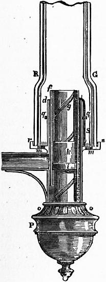
Fig. 1.
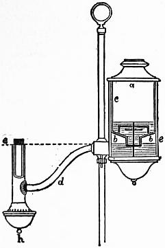
Fig. 2.—Section of Reading Lamp.
A typical example of the Argand burner and chimney is represented in fig. 1, in which the burner is composed of three tubes, d, f, g. The tube g is soldered to the bottom of the tube d, just above o, and the interval between the outer surface of the tube g and the inner surface of the tube d is an annular cylindrical cavity closed at the bottom, containing the cylindrical cotton wick immersed in oil. The wick is fixed to the wick tube ki, which is capable of being moved spirally; within the annular cavity is also the tube f, which can be moved round, and serves to elevate and depress the wick. P is a cup that screws on the bottom of the tube d, and receives the superfluous oil that drops down from the wick along the inner surface of the tube g. The air enters through the holes o, o, and passes up through the tube g to maintain the combustion in the interior of the circular flame. The air which maintains the combustion on the exterior part of the wick enters through the holes m, with which rn is perforated. When the air in the chimney is rarefied by the heat of the flame, the surrounding heavier air, entering the lower part of the chimney, passes upward with a rapid current, to restore the equilibrium. RG is the cylindrical glass chimney with a shoulder or constriction at R, G. The oil flows from a side reservoir, and occupies the cavity between the tubes g and d. The part ki is a short tube, which receives the circular wick, and slides spirally on the tube g, by means of a pin working in the hollow spiral groove on the exterior surface of g. The wick-tube has also a catch, which works in a perpendicular slit in the tube f; and, by turning the tube f, the wick-tube will be raised or lowered, for which purpose a ring, or gallery, rn, fits on the tube d, and receives the glass chimney RG; a wire S is attached to the tube f, and, bending over, descends along the outside of d. The part rn, that supports the glass chimney, is connected by four other wires with the ring q, which surrounds the tube d, and can be moved round. When rn is turned round, it carries with it the ring q, the wire S, and the tube f, thus raising or depressing the wick.
A device in the form of a small metallic disk or button, known as the Liverpool button from having been first adopted in the so-called Liverpool lamp, effects for the current of air passing up the interior of the Argand burner the same object as the constriction of the chimney RG secures in the case of the external tube. The button fixed on the end of a wire is placed right above the burner tube g, and throws out equally all round against the flame the current of air which passes up through g. The result of these expedients, when properly applied, is the production of an exceedingly solid brilliant white light, absolutely smokeless, this showing that the combustion of the oil is perfectly accomplished.
The means by which a uniformly regulated supply of oil is brought to the burner varies with the position of the oil reservoir. In some lamps, not now in use, by ring-formed reservoirs and other expedients, the whole of the oil was kept as nearly as possible at the level of the burner. In what are termed fountain reading, or study lamps, the principal reservoir is above the burner level, and various means are adopted for maintaining a supply from them at the level of the burner. But the most convenient position for the oil reservoir in lamps for general use is directly under the burner, and in this case the stand of the lamp itself is utilized as the oil vessel. In the case of fixed oils, as the oils of animal and vegetable origin used to be called, it is necessary with such lamps to introduce some appliance for forcing a supply of oil to the burner, and many methods of effecting this were devised, most of which were ultimately superseded by the moderator lamp. The Carcel or pump lamp, invented by B. G. Carcel in 1800, is still to some extent used in France. It consists of a double piston or pump, forcing the oil through a tube to the burner, worked by clockwork.
A form of reading lamp still in use is seen in section in fig. 2. The lamp is mounted on a standard on which it can be raised or lowered at will, and fixed by a thumb screw. The oil reservoir is in two parts, the upper ac being an inverted flask which fits into bb, from which the burner is directly fed through the tube d; h is an overflow cup for any oil that escapes at the burner, and it is pierced with air-holes for admitting the current of air to the centre tube of the Argand burner. The lamp is filled with oil by withdrawing the flask ac, filling it, and inverting it into its place. The under reservoir bb fills from it to the burner level ee, on a line with the mouth of ac. So soon as that level falls below the mouth of ac, a bubble of air gets access to the upper reservoir, and oil again fills up bb to the level ee.
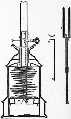
Fig. 3.—Section of Moderator Lamp.
The moderator lamp (fig. 3), invented by Franchot about 1836, from the simplicity and efficiency of its arrangements rapidly superseded almost all other forms of mechanical lamp for use with animal and vegetable oils. The two essential features of the moderator lamp are (1) the strong spiral spring which, acting on a piston within the cylindrical reservoir of the lamp, serves to propel the oil to the burner, and (2) the ascending tube C through which the oil passes upwards to the burner. The latter consist of two sections, the lower fixed to and passing through the piston A into the oil reservoir, and the upper attached to the burner. The lower or piston section moves within the upper, which forms a sheath enclosing nearly its whole length when the spring is fully wound up. Down the centre of the upper tube passes a wire, “the moderator,” G, and it is by this wire that the supply of oil to the burner is regulated. The spring exerts its greatest force on the oil in the reservoir when it is fully wound up, and in proportion as it expands and descends its power decreases. But when the apparatus is wound up the wire passing down the upper tube extends throughout the whole length of the lower and narrower piston tube, obstructing to a certain extent the free flow of the oil. In proportion as the spring uncoils, the length of the wire within the lower tube is decreased; the upward flow of oil is facilitated in the same ratio as the force urging it upwards is weakened. In all mechanical lamps the flow is in excess of the consuming capacity of the burner, and in the moderator the surplus oil, flowing over the wick, falls back into the reservoir above the piston, whence along with new supply oil it descends into the lower side by means of leather valves a, a. B represents the rack which, with the pinion D, winds up the spiral spring hard against E when the lamp is prepared for use. The moderator wire is seen separately in GG; and FGC illustrates the arrangement of the sheathing tubes, in the upper section of which the moderator is fixed.
As early as 1781 the idea was mooted of burning naphtha, obtained by the distillation of coal at low temperatures, for illuminating purposes, and in 1820, when coal gas was struggling into prominence, light oils obtained Mineral oils. by the distillation of coal tar were employed in the Holliday lamp, which is still the chief factor in illuminating the street barrow of the costermonger. In this lamp the coal naphtha is in a conical reservoir, from the apex of which it flows slowly down through a long metal capillary to a rose burner, which, heated up by the flame, vaporizes the naphtha, and thus feeds the ring of small jets of flame escaping from its circumference.
It was in 1847 that James Young had his attention drawn to an exudation of petroleum in the Riddings Colliery at Alfreton, in Derbyshire, and found that he could by distillation obtain from it a lubricant of considerable value. The commercial success of this material was accompanied by a failure of the supply, and, rightly imagining that as the oil had apparently come from the Coal Measures, it might be obtained by distillation from material of the same character, Young began investigations in this direction, and in 1850 started distilling oils from a shale known as the “Bathgate mineral,” in this way founding the Scotch oil industry. At first little attention was paid to the fitness of the oil for burning purposes, although in the early days at Alfreton Young attempted to burn some of the lighter distillates in an Argand lamp, and later in a lamp made many years before for the consumption of turpentine. About 1853, however, it was noticed that the lighter distillates were being shipped to Germany, where lamps fitted for the consumption of the grades of oil now known as lamp oil were being made by Stohwasser of Berlin; some of these lamps were imported, and similar lamps were afterwards manufactured by Laidlaw in Edinburgh.
In Pennsylvania in 1859 Colonel E. L. Drake’s successful boring for petroleum resulted in the flooding of the market with oil at prices never before deemed possible, and led to the introduction of lamps from Germany for its consumption. Although the first American patent for a petroleum lamp is dated 1859, that year saw forty other applications, and for the next twenty years they averaged about eighty a year.
English lamp-makers were not behind in their attempts to improve on the methods in use for producing the highest results from the various grades of oil, and in 1865 Hinks introduced the duplex burner, while later improvements made in various directions, by Hinks, Silber, and Defries led to the high degree of perfection to be found in the lamps of to-day. Mineral oil for lamps as used in England at the present time may be defined as consisting of those portions of the distillate from shale oil or crude petroleum which have their flash-point above 73° F., and which are mobile enough to be fed by capillarity in sufficient quantity to the flame. The oil placed in the lamp reservoir is drawn up by the capillarity of the wick to the flame, and being there volatilized, is converted by the heat of the burning flame into a gaseous mixture of hydrogen and hydrocarbons, which is ultimately consumed by the oxygen of the air and converted into carbon dioxide and water vapour, the products of complete combustion.
To secure high illuminating power, together with a smokeless flame and only products of complete combustion, strict attention must be paid to several important factors. In the first place, the wick must be so arranged as to supply the right quantity of oil for gasification at the burner-head—the flame must be neither starved nor overfed: if the former is the case great loss of light is occasioned, while an excess of oil, by providing more hydrocarbons than the air-supply to the flame can completely burn, gives rise to smoke and products of incomplete combustion. The action of the wick depending on the capillary action of the microscopic tubes forming the cotton fibre, nothing but long-staple cotton of good quality should be employed; this should be spun into a coarse loose thread with as little twist in it as possible, and from this the wick is built up. Having obtained a wick of soft texture and loose plait, it should be well dried before the fire, and when put in position in the lamp must fill the wick-holder without being compressed. It should be of sufficient length to reach to the bottom of the oil reservoir and leave an inch or two on the bottom. Such a wick will suck up the oil in a regular and uniform way, provided that the level of the oil is not allowed to fall too low in the lamp, but it must be remembered that the wick acts as a filter for the oil, and that if any sediment be present it will be retained by and choke the capillaries upon which the action of the wick depends, so that a wick should not be used for too long a time. A good rule is that the wick should, when new, trail for 2 in. on the bottom of the oil vessel, and should be discarded when these 2 in. have been burnt off.
When the lamp is lighted the oil burns with a heavy, smoky flame, because it is not able to obtain sufficient oxygen to complete the combustion, and not only are soot flakes produced, but products of incomplete combustion, such as carbon monoxide and even petroleum vapour, escape—the first named highly injurious to health, and the second of an offensive odour. To supply the necessary amount of air to the flame, an artificial draught has to be created which shall impinge upon the bottom of the flame and sweep upwards over its surface, giving it rigidity, and by completing the combustion in a shorter period of time than could be done otherwise, increasing the calorific intensity and thus raising the carbon particles in the flame to a far higher incandescence so as to secure a greater illuminating power. This in practice has been done in two ways, first by drawing in the air by the up-suck of the heated and expanded products of combustion in a chimney fitted over the flame, and secondly by creating a draught from a small clockwork fan in the base of the lamp. It is necessary to break the initial rush of the draught: this is mostly effected by disks of perforated metal in the base of the burner, called diffusers, while the metal dome which surrounds and rises slightly above the wick-holder serves to deflect the air on to the flame, as in the Wanzer lamp. These arrangements also act to a certain extent as regenerators, the air passing over the heated metal surfaces being warmed before reaching the flame, whilst disks, cones, buttons, perforated tubes, inner air-tubes, &c., have been introduced to increase the illuminating power and complete the combustion.
Table I.
Type. Name. Grains of Oil per candle-power per hour. Total Candle-power.
American. Russian. American. Russian.
Circular wick Veritas, 60-line 64.5 112.5 122.5 78
Veritas, 30-line 42.5 50. 60 60
Veritas, 20-line 43.75 58.5 40 35
Ariel, 12-line center draught 52.8 70.9 18 18
Reading, 14-line 97.9 85.4 12 12
Kosmos, 10-line 63.9 97.2 9 9
Wizard, 15-line 56.9 51.3 18 19
Flat wick, single Wanzer, no glass 42.6 48.3 17 17
Solid slip, gauze and cone 84.4 84.4 8 8
Old slip, fixed gauze 60.9 89.3 7 7
Flat wick, duplex Feeder wick 56.2 55.7 20 22
Ordinary 51.2 46.6 20 22
American oil—Sp. gr. 0.7904; flash-point, 110°F. Russian oil—Sp. gr. 0.823; flash-point, 83° F.
According to Sir Boverton Redwood, duplex burners which give a flame of 28 candle-power have an average oil consumption of 50 grains per candle per hour, while Argand flames of 38 candle-power consume about 45 grains of oil per candle per hour. These figures were obtained from lamps of the best types, and to obtain information as to the efficiency of the lamps used in daily practice, a number of the most popular types were examined, using both American and Russian oil. The results obtained are embodied in Table 1. The first noteworthy point in this table is the apparent superiority of the American over Russian oil in the majority of the lamps employed, and there is no doubt that the bulk of the lamps on the market are constructed to burn American or shale oil. A second interesting point is that with the flat-flame lamps the Russian oil is as good as the American. We have Redwood’s authority, moreover, for the fact that after prolonged burning the Russian oil, even in lamps least suited to it, gives highly improved results. Although the average consumption with these lamps is close upon 60 grains per candle with American oil, yet some of the burners are so manifestly wasteful that 50 grains per candle-power per hour is the fairest basis to take for any calculation as to cost.
The dangers of the mineral oil lamp, which were a grave drawback in the past, have been very much reduced by improvements in construction and quality, and if it were possible to abolish the cheap and dangerous rubbish sold in poor neighbourhoods, and to prevent the use of side-fillers and glass reservoirs in lamps of better quality, a still larger reduction in the number of accidents would take place. In the use of the lamp for domestic purposes only soft well-fitting wicks should be employed, and the lamp should be filled with oil each day so as never to allow it to burn too low and so leave a large space above the surface of the oil in the reservoir. The lamp should never be moved whilst alight, and it should only be put out by means of a proper extinguisher or by blowing across the top instead of down the chimney. By these means the risk of accident would be so reduced as to compare favourably with other illuminants.