VOLUME VIII SLICE IX Dyer to Echidna (continued 3)
Reading edition
It remains to add, that the rise of temperature which may be permitted in any part of a dynamo after a prolonged run is very generally placed at about 70° Fahr. above the surrounding air. Such a limit in ordinary conditions of working leads to a final temperature of about 170° Fahr., beyond which the durability of the insulation of the wires is liable to be injuriously affected. Upon some such basis the output of a dynamo in continuous working is rated, although for short periods of, say, two hours the normal full-load current of a large machine may be exceeded by some 25% without unduly heating the armature.
For the electro-deposition of metals or the electrolytic treatment of ores a continuous current is a necessity; but, apart from such use, the purposes from which the continuous-current dynamo is well adapted are so numerous that Uses of continuous current dynamos. they cover nearly the whole field of electrical engineering, with one important exception. To meet these various uses, the pressures for which the machine is designed are of equally wide range; for the transmission of power over long distances they may be as high as 3000 volts, and for electrolytic work as low as five. Each electrolytic bath, with its leads, requires on an average only some four or five volts, so that even when several are worked in series the voltage of the dynamo seldom exceeds 60. On the other hand, the current is large and may amount to as much as from 1000 to 14,000 amperes, necessitating the use of two commutators, one at either end of the armature, in order to collect the current without excessive heating of the sectors and brushes. The field-magnets are invariably shunt-wound, in order to avoid reversal of the current through polarization at the electrodes of the bath. For incandescent lighting by glow lamps, the requirements of small isolated installations and of central stations for the distribution of electrical energy over large areas must be distinguished. For the lighting of a private house or small factory, the dynamo giving from 5 to 100 kilo-watts of output is commonly wound for a voltage of 100, and is driven by pulley and belt from a gas, oil or steam-engine; or, if approaching the higher limit above mentioned, it is often directly coupled to the crank-shaft of the steam-engine. If used in conjunction with an accumulator of secondary cells, it is shunt-wound, and must give the higher voltage necessary to charge the battery; otherwise it is compound-wound, in order to maintain the pressure on the lamps constant under all loads within its capacity. The compound-wound dynamo is likewise the most usual for the lighting of steamships, and is then directly coupled to its steam-engine; its output seldom exceeds 100 kilo-watts, at a voltage of 100 or 110. For larger installations a voltage of 250 is commonly used, while for central-station work, economy in the distributing mains dictates a higher voltage, especially in connexion with a three-wire system; the larger dynamos may then give 500 volts, and be connected directly across the two outer wires. A pair of smaller machines coupled together, and each capable of giving 250 volts, are often placed in series across the system, with their common junction connected to the middle wire; the one which at any time is on the side carrying the smaller current will act as a motor and drive the other as a dynamo, so as to balance the system. The directly-coupled steam dynamo may be said to have practically displaced the belt- or rope-driven sets which were formerly common in central stations. The generating units of the central station are arranged in progressive sizes, rising from, it may be, 250 or 500 horse-power up to 750 or 1000, or in large towns to as much as 5000 horse-power. If for lighting only, they are usually shunt-wound, the regulation of the voltage, to keep the pressure constant on the distributing system under the gradual changes of load, being effected by variable resistances in the shunt circuit of the field-magnets.
Generators used for supplying current to electric tramways are commonly wound for 500 volts at no load and are over-compounded, so that the voltage rises to 550 volts at the maximum load, and thus compensates for the loss of volts over the transmitting lines. For arc lighting it was formerly usual to employ a class of dynamo which, from the nature of its construction, was called an “open-coil” machine, and which gave a unidirectional but pulsating current. Of such machines the Brush and Thomson-Houston types were very widely used; their E.M.F. ranged from 2000 to 3000 volts for working a large number of arcs in series, and by means of special regulators their current was maintained constant over a wide range of voltage. But as their efficiency was low and they could not be applied to any other purpose, they have been largely superseded in central stations by closed-coil dynamos or alternators, which can also be used for incandescent lighting. In cases where the central station is situated at some distance from the district to which the electric energy is to be supplied, voltages from 1000 to 2000 are employed, and these are transformed down at certain distributing centres by continuous-current transformers (see Transformers and Electricity Supply). These latter machines are in reality motor-driven dynamos, and hence are also called motor-generators; the armatures of the motor and dynamo are often wound on the same core, with a commutator at either end, the one to receive the high-pressure motor current, and the other to collect the low-pressure current furnished by the dynamo.
In all large central stations it is necessary that the dynamos should be capable of being run in parallel, so that their outputs may be combined on the same “omnibus bars” and thence distributed to the network of feeders. With simple shunt-wound machines this is easily effected by coupling together terminals of like sign when the voltage of the two or more machines are closely equal. With compound-wound dynamos not only must the external terminals of like sign be coupled together, but the junctions of the brush leads with the series winding must be connected by an “equalizing” lead of low resistance; otherwise, should the E.M.F. of one machine for any reason fall below the voltage of the omnibus bars, there is a danger of its polarity being reversed by a back current from the others with which it is in parallel.
Owing to the necessary presence in the continuous-current dynamo of the commutator, with its attendant liability to sparking at the brushes, and further, owing to the difficulty of insulating the rotating armature wires, a pressure of 3000 volts has seldom been exceeded in any one continuous-current machine, and has been given above as the limiting voltage of the class. If therefore it is required to work with higher pressures in order to secure economy in the transmitting lines, two or more machines must be coupled in series by connecting together terminals which are of unlike sign.19 The stress of the total voltage may still fall on the insulation of the winding from the body of the machine; hence for high-voltage transmission of power over very long distances, the continuous-current dynamo in certain points yields in convenience to the alternator. In this there is no commutator, the armature coils may be stationary and can be more thoroughly insulated, while further, if it be thought undesirable to design the machine for the full transmitting voltage, it is easy to wind the armature for a low pressure; this can be subsequently transformed up to a high pressure by means of the alternating-current transformer, which has stationary windings and so high an efficiency that but little loss arises from its use. With these remarks, the transition may be made to the fuller discussion of the alternator.
Alternators.
The frequency employed in alternating-current systems for distributing power and light varies between such wide limits as 25 and 133; yet in recent times the tendency has been towards standard frequencies of 25, 50 Frequency. and 100 as a maximum. High frequencies involve more copper in the magnet coils, owing to the greater number of poles, and a greater loss of power in their excitation, but the alternator as a whole is somewhat lighter, and the transformers are cheaper. On the other hand, high frequency may cause prejudicial effects, due to the inductance and capacity of the distributing lines; and in asynchronous motors used on polyphase systems the increased number of poles necessary to obtain reasonable speeds reduces their efficiency, and is otherwise disadvantageous, especially for small horse-powers. A frequency lower than 40 is, however, not permissible where arc lighting is to form any considerable portion of the work and is to be effected by the alternating current without rectification, since below this value the eye can detect the periodic alteration in the light as the carbons alternately cool and become heated. Thus for combined lighting and power 50 or 60 are the most usual frequencies; but if the system is designed solely or chiefly for the distribution of power, a still lower frequency is preferable. On this account 25 was selected by the engineers for the Niagara Falls power transmission, after careful consideration of the problem, and this frequency has since been widely adopted in similar cases.
The most usual type of heteropolar alternator has an internal rotating field-magnet system, and an external stationary armature, as in fig. 10. The coils of the armature, which must for high voltages be heavily insulated, are then Alternator construction. not subjected to the additional stresses due to centrifugal force; and further, the collecting rings which must be attached to the rotating portion need only transmit the exciting current at a low voltage.
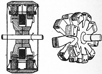
Fig. 36.
The homopolar machine possesses the advantages that only a single exciting coil is required, whatever the number of polar projections, and that both the armature and field-magnet coils may be stationary. From fig. 8 it will be seen that it is not essential that the exciting coil should revolve with the internal magnet, but it may be supported from the external stationary armature while still embracing the central part of the rotor. The E.M.F. is set up in the armature coils through the periodic variation of the flux through them as the iron projections sweep past, and these latter may be likened to a number of “keepers,” which complete the magnetic circuit. From the action of the rotating iron masses they may also be considered as the inducing elements or “inductors,” and the homopolar machine is thence also known as the “inductor alternator.” If the end of the rotor marked S in fig. 8 is split up into a number of S polar projections similar to the N poles, a second set of armature coils may be arranged opposite to them, and we obtain an inductor alternator with double armature. Or the polar projections at the two ends may be staggered, and a single armature winding be passed straight through the armature, as in fig. 36, which shows at the side the appearance of the revolving inductor with its crown of polar projections in one ring opposite to the gaps between the polar projections of the other ring. But in spite of its advantage of the single stationary exciting coil, the inductor alternator has such a high degree of leakage, and the effect of armature reaction is so detrimental in it, that the type has been gradually abandoned, and a return has been almost universally made to the heteropolar alternator with internal poles radiating outwards from a circular yoke-ring. The construction of a typical machine of this class is illustrated in fig. 37.
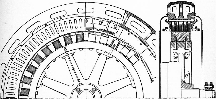
Fig. 37.
Since the field-magnet coils rotate, they must be carefully designed to withstand centrifugal force, and are best composed of flat copper strip wound on edge with thin insulation between adjacent layers. The coil is secured by the edges of the pole-shoes which overhang the pole and tightly compress the coil against the yoke-ring; the only effect from centrifugal force is then to compress still further the flat turns of copper against the pole-shoes without deformation. The poles are either of cast steel of circular or oblong section, bolted to the rim of the yoke-ring, or are built up of thin laminations of sheet steel. When the peripheral speed is very high, the yoke-ring will be of cast steel or may itself be built up of sheet steel laminations, this material being reliable and easily tested to ensure its sound mechanical strength. If the armature slots are open, the pole-pieces will in any case be laminated to reduce the eddy currents set up by the variation of the flux-density.
Owing to the great number of poles20 of the alternator when driven by a reciprocating steam-engine, the diameter of its rotor is usually larger and its length less than in the continuous-current dynamo of corresponding output. The support of the armature core when of large diameter is therefore a more difficult problem, since, apart from any magnetic strains to which it may be subjected, its own weight tends to deform it. The segmental core-disks are usually secured to the internal circumference of a circular cast iron frame; the latter has a box section of considerable radial depth to give stiffness to it, and the disks are tightly clamped between internal flanges, one being a fixed part of the frame and the other loose, with transverse bolts passing right through from side to side (fig. 37). In order to lessen the weight of the structure and its expense in material, the cast iron frame has in some cases been entirely dispensed with, and braced tie-rods have been used to render the effective iron of the armature core-disks self-supporting.
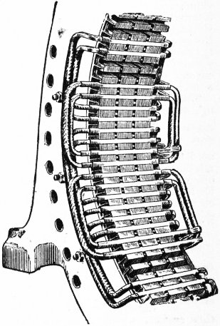
Fig. 38.
Owing to the high speed of the turbo-alternator, its rotor calls for the utmost care in its design to withstand the effect of centrifugal force without any shifting of the exciting coils, and to secure a perfect balance.
The appearance of the armature of a typical three-phase alternator is illustrated in fig. 38, which shows a portion of the lower half after removal of the field-magnet.
With open slots the coils, after being wound on formers to the required shape, are thoroughly impregnated with insulating compound, dried, and after a further wrapping with several layers of insulating material, finally pressed into the slots together with a sheet of leatheroid or flexible micanite. The end-connexions of each group of coils of one phase project straight out from the slots or are bent upwards alternately with those of the other phases, so that they may clear one another (fig. 37). A wooden wedge driven into a groove at the top of each slot is often used to lock the coil in place. With slots nearly closed at the top, the coils are formed by hand by threading the wire through tubes of micanite or specially prepared paper lining the slots; or with single-turn loops, stout bars of copper of U-shape can be driven through the slots and closed by soldered connexions at the other end.
The first experimental determination of the shape of the E.M.F. curve of an alternator was made by J. Joubert in 1880. A revolving contact-maker charged a condenser with the E.M.F. produced by the armature at a particular instant during Shape of E.M.F. curve. each period. The condenser was discharged through a ballistic galvanometer, and from the measured throw the instantaneous E.M.F. could be deduced. The contact-maker was then shifted through a small angle, and the instantaneous E.M.F. at the new position corresponding to a different moment in the period was measured; this process was repeated until the E.M.F. curve for a complete period could be traced. Various modifications of the same principle have since been used, and a form of “oscillograph” (q.v.) has been perfected which is well adapted for the purpose of tracing the curves both of E.M.F. and of current. The machine on which Joubert carried out his experiments was a Siemens disk alternator having no iron in its armature, and it was found that the curve of E.M.F. was practically identical with a sine curve. The same law has also been found to hold true for a smooth-core ring or drum armature, but the presence of the iron core enables the armature current to produce greater distorting effect, so that the curves under load may vary considerably from their shape at no load. In toothed armatures, the broken surface of the core, and the still greater reaction from the armature current, may produce wide variations from the sine law, the general tendency being to give the E.M.F. curve a more peaked form. The great convenience of the assumption that the E.M.F. obeys the sine law has led to its being very commonly used as the basis for the mathematical analysis of alternator problems; but any deductions made from this premiss require to be applied with caution if they are likely to be modified by a different shape of the curve. Further, the same alternator will give widely different curves even of E.M.F., and still more so of current, according to the nature of the external circuit to which it is connected. As will be explained later, the phase of the current relatively to the E.M.F. depends not only on the inductance of the alternator itself, but also upon the inductance and capacity of the external circuit, so that the same current will produce different effects according to the amount by which it lags or leads. The question as to the relative advantages of differently shaped E.M.F. curves has led to much discussion, but can only be answered by reference to the nature of the work that the alternator has to do—i.e. whether it be arc lighting, motor driving, or incandescent lighting through transformers. The shape of the E.M.F. curve is, however, of great importance in one respect, since upon it depends the ratio of the maximum instantaneous E.M.F. to the effective value, and the insulation of the entire circuit, both external and internal, must be capable of withstanding the maximum E.M.F. While the maximum value of the sine curve is √2 or 1.414 times the effective value, the maximum value of a Λ curve is 1.732 times the effective value, so that for the same effective E.M.F. the armature wires must not only be more heavily insulated than in the continuous-current dynamo, but also the more peaked the curve the better must be the insulation.
Since an alternating current cannot be used for exciting the field-magnet, recourse must be had to some source of a direct current. This is usually obtained from a small auxiliary continuous-current dynamo, called an exciter, which may Excitation. be an entirely separate machine, separately driven and used for exciting several alternators, or may be driven from the alternator itself; in the latter case the armature of the exciter is often coupled directly to the rotating shaft of the alternator, while its field-magnet is attached to the bed-plate. Although separate excitation is the more usual method, the alternator can also be made self-exciting if a part or the whole of the alternating current is “rectified,” and thus converted into a direct current.
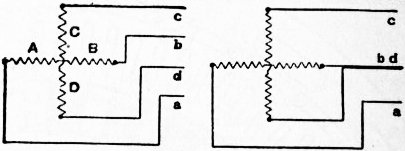
Fig. 39.
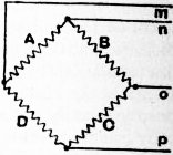
Fig. 40.
The general idea of the polyphase alternator giving two or more E.M.F.’s of the same frequency, but displaced in phase, has been already described. The several phases may be entirely independent, and such was the case with the early polyphase Quarter-phase alternators. machines of Gramme, who used four independent circuits, and also in the large two-phase alternators designed by J.E.H. Gordon in 1883. If the phases are thus entirely separate, each requires two collector rings and two wires to its external circuit, i.e. four in all for two-phase and six for three-phase machines. The only advantage of the polyphase machine as thus used is that the whole of the surface of the armature core may be efficiently covered with winding, and the output of the alternator for a given size be thereby increased. It is, however, also possible so to interlink the several circuits of the armature that the necessary number of transmitting lines to the external circuits may be reduced, and also the weight of copper in them for a given loss in the transmission.21 The condition which obviously must be fulfilled, for such interlinking of the phases to be possible, is that in the lines which are to meet at any common junction the algebraic sum of the instantaneous currents, reckoned as positive if away from such junction and as negative if towards it, must be zero. Thus if the phases be diagrammatically represented by the relative angular position of the coils in fig. 39, the current in the coils A and B differs in phase from the current in the coils C and D by a quarter of a period or 90°; hence if the two wires b and d be replaced by the single wire bd, this third wire will serve as a common path for the currents of the two phases either outwards or on their return. At any instant the value of the current in the third wire must be the vector sum of the two currents in the other wires, and if the shape of the curves of instantaneous E.M.F. and current are identical, and are assumed to be sinusoidal, the effective value of the current in the third wire will be the vector sum of the effective values of the currents in the other wires; in other words, if the system is balanced, the effective current in the third wire is √2, or 1.414 times the current in either of the two outer wires. Since the currents of the two phases do not reach their maximum values at the same time, the sectional area of the third wire need not be twice that of the others; in order to secure maximum efficiency by employing the same current density in all three wires, it need only be 40% greater than that of either of the outer wires. The effective voltage between the external leads may in the same way be calculated by a vector diagram, and with the above star connexion the voltage between the outer pair of wires a and c is √2, or 1.414 times the voltage between either of the outer wires and the common wire bd. Next, if the four coils are joined up into a continuous helix, just as in the winding of a continuous-current machine, four wires may be attached to equidistant points at the opposite ends of two diameters at right angles to each other (fig. 40). Such a method is known as the mesh connexion, and gives a perfectly symmetrical four-phase system of distribution. Four collecting rings are necessary if the armature rotates, and there is no saving in copper in the transmitting lines; but the importance of the arrangement lies in its use in connexion with rotary converters, in which it is necessary that the winding of the armature should form a closed circuit. If e = the effective voltage of one phase A, the voltage between any pair of adjacent lines in the diagram is e, and between m and o or n and p is e √2. The current in any line is the resultant of the currents in the two phases connected to it, and its effective value is c √2, where c is the current of one phase.
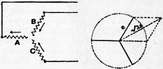
Fig. 41.
When we pass to machines giving three phases differing by 120°, the same methods of star and mesh connexion find their analogies. If the current in coil A (fig. 41) is flowing away from the centre, and has its maximum value, the Three-phase alternators. currents in coils B and C are flowing towards the centre, and are each of half the magnitude of the current in A; the algebraic sum of the currents is therefore zero, and this will also be the case for all other instants. Hence the three coils can be united together at the centre, and three external wires are alone required. In this star or “Y” connexion, if e be the effective voltage of each phase, or the voltage between any one of the three collecting rings and the common connexion, the volts between any pair of transmitting lines will be E = e √3 (fig. 41); if the load be balanced, the effective current C in each of the three lines will be equal, and the total output in watts will be W = 3Ce = 3CE / √3 = 1.732 EC, or 1.732 times the product of the effective voltage between the lines and the current in any single line. Next, if the three coils are closed upon themselves in a mesh or delta fashion (fig. 42), the three transmitting wires may be connected to the junctions of the coils (by means of collecting rings if the armature rotates). The voltage E between any pair of wires is evidently that generated by one phase, and the current in a line wire is the resultant of that in two adjacent phases; or in a balanced system, if c be the current in each phase, the current in the line wire beyond a collecting ring is C = c√3, hence the watts are W = 3cE = 3CE / √3 = 1.732 EC, as before. Thus any three-phase winding may be changed over from the star to the delta connexion, and will then give 1.732 times as much current, but only 1/1.732 times the voltage, so that the output remains the same.
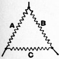
Fig. 42.
The “armature reaction” of the alternator, when the term is used in its widest sense to cover all the effects of the alternating current in the armature as linked with a magnetic circuit or circuits, may be divided into three items which are Armature reaction in alternators different in their origin and consequences. In the first place the armature current produces a self-induced flux in local circuits independent of the main magnetic circuit, as e.g. linked with the ends of the coils as they project outwards from the armature core; such lines may be called “secondary leakage,” of which the characteristic feature is that its amount is independent of the position of the coils relatively to the poles. The alternations of this flux give rise to an inductive voltage lagging 90° behind the phase of the current, and this leakage or reactance voltage must be directly counterbalanced electrically by an equal component in the opposite sense in the voltage from the main field. The second and third elements are more immediately magnetic and are entirely dependent upon the position of the coils in relation to the poles and in relation to the phase of the current which they then carry. When the side of a drum coil is immediately under the centre of a pole, its ampere-turns are cross-magnetizing, i.e. produce a distortion of the main flux, displacing its maximum density to one or other edge of the pole. When the coil-side is midway between the poles and the axes of coil and pole coincide, the coil stands exactly opposite to the pole and embraces the same magnetic circuit as the field-magnet coils; its turns are therefore directly magnetizing, either weakening or strengthening the main flux according to the direction of the current. In intermediate positions the ampere-turns of the coil gradually pass from cross to direct and vice versa. When the instantaneous values of either the cross or direct magnetizing effect are integrated over a period and averaged, due account being taken of the number of slots per coil-side and of the different phases of the currents in the polyphase machine, expressions are obtained for the equivalent cross and direct ampere-turns of the armature as acting upon a pair of poles. For a given winding and current, the determining factor in either the one or the other is found to be the relative phase angle between the axis of a coil in its position when carrying the maximum current and the centre of a pole, the transverse reaction being proportional to the cosine of this angle, and the direct reaction to its sine. If the external circuit is inductive, the maximum value of the current lags behind the E.M.F. and so behind the centre of the pole; such a negative angle of lag causes the direct magnetizing turns to become back turns, directly weakening the main field and lowering the terminal voltage. Thus, just as in the continuous-current dynamo, for a given voltage under load the excitation between the pole-pieces Xp must not only supply the net excitation required over the air-gaps, armature core and teeth, but must also balance the back ampere-turns Xb of the armature.
Evidently therefore the characteristic curve connecting armature current and terminal volts will with a constant exciting current depend on the nature of the load, whether inductive or non-inductive, and upon the amount of inductance already possessed by the armature itself. With an inductive load it will fall more rapidly from its initial maximum value, or, conversely, if the initial voltage is to be maintained under an increasing load, the exciting current will have to be increased more than if the load were non-inductive. In practical working many disadvantages result from a rapid drop of the terminal E.M.F. under increasing load, so that between no load and full load the variation in terminal voltage with constant excitation should not exceed 15%. Thus the output of an alternator is limited either by its heating or by its armature reaction, just as is the output of a continuous-current dynamo; in the case of the alternator, however, the limit set by armature reaction is not due to any sparking at the brushes, but to the drop in terminal voltage as the current is increased, and the consequent difficulty in maintaining a constant potential on the external circuit.
The joint operation of several alternators so that their outputs may be delivered into the same external circuit is sharply distinguished from the corresponding problem in continuous-current dynamos by the necessary condition that they The coupling of alternators. must be in synchronism, i.e. not only must they be so driven that their frequency is the same, but their E.M.F.’s must be in phase or, as it is also expressed, the machines must be in step. Although in practice it is impossible to run two alternators in series unless they are rigidly coupled together—which virtually reduces them to one machine—two or more machines can be run in parallel, as was first described by H. Wilde in 1868 and subsequently redemonstrated by J. Hopkinson and W.G. Adams in 1884. Their E.M.F.’s should be as nearly as possible in synchronism, but, as contrasted with series connexion, parallel coupling gives them a certain power of recovery if they fall out of step, or are not in exact synchronism when thrown into parallel. In such circumstances a synchronizing current passes between the two machines, due to the difference in their instantaneous pressures; and as this current agrees in phase more nearly with the leading than with the lagging machine, the former machine does work as a generator on the latter as a motor. Hence the lagging machine is accelerated and the leading machine is retarded, until their frequencies and phase are again the same.
The chief use of the alternator has already been alluded to. Since it can be employed to produce very high pressures either directly or through the medium of transformers, it is specially adapted to the electrical transmission of Uses of alternators. energy over long distances.22 In the early days of electric lighting, the alternate-current system was adopted for a great number of central stations; the machines, designed to give a pressure of 2000 volts, supplied transformers which were situated at considerable distances and spread over large areas, without an undue amount of copper in the transmitting lines. While there was later a tendency to return to the continuous current for central stations, owing to the introduction of better means for economizing the weight of copper in the mains, the alternating current again came into favour, as rendering it possible to place the central station in some convenient site far away from the district which it was to serve. The pioneer central station in this direction was the Deptford station of the London Electric Supply Corporation, which furnished current to the heart of London from a distance of 7 m. In this case, however, the alternators were single-phase and gave the high pressure of 10,000 volts immediately, while more recently the tendency has been to employ step-up transformers and a polyphase system. The advantage of the latter is that the current, after reaching the distant sub-stations, can be dealt with by rotary converters, through which it is transformed into a continuous current. The alternator is also used for welding, smelting in electric furnaces, and other metallurgical processes where heating effects are alone required; the large currents needed therein can be produced without the disadvantage of the commutator, and, if necessary, transformers can be interposed to lower the voltage and still further increase the current. The alternating system can thus meet very various needs, and its great recommendation may be said to lie in the flexibility with which it can supply electrical energy through transformers at any potential, or through rotary converters in continuous-current form.
Authorities.—For the further study of the dynamo, the following may be consulted, in addition to the references already given:—
General: S.P. Thompson, Dynamo-Electric Machinery—Continuous-Current Machines (1904), Alternating-Current Machinery (1905, London); G. Kapp, Dynamos, Alternators and Transformers (London, 1893); Id., Electric Transmission of Energy (London, 1894); Id., Dynamo Construction; Electrical and Mechanical (London, 1899); H.F. Parshall and H.M. Hobart, Electric Generators (London, 1900); C.C. Hawkins and F. Wallis, The Dynamo (London, 1903); E. Arnold, Konstruktionstafeln für den Dynamobau (Stuttgart, 1902); C.P. Steinmetz, Elements of Electrical Engineering (New York, 1901).
Continuous-Current Dynamos: J. Fischer-Hinnen, Continuous-Current Dynamos (London, 1899); E. Arnold, Die Gleichstrommaschine (Berlin, 1902); F. Niethammer, Berechnung und Konstruktion der Gleichstrommaschinen und Gleichstrommotoren (Stuttgart, 1904).
Alternators: D.C. Jackson and J.P. Jackson, Alternating Currents and Alternating Current Machinery (New York, 1903); J.A. Fleming, The Alternate Current Transformer (London, 1899); C.P. Steinmetz, Alternating Current Phenomena (New York, 1900); E. Arnold, Die Wechselstromtechnik (Berlin, 1904); S.P. Thompson, Polyphase Electric Currents (London, 1900); A. Stewart, Modern Polyphase Machinery (London, 1906); M. Oudin, Standard Polyphase Apparatus and Systems (New York, 1904).
(C. C. H.)
1 Experimental Researches in Electricity, series ii. § 6, pars. 256, 259-260, and series xxviii. § 34.
2 Ibid. series i. § 4, pars. 84-90.
3 “On the Physical Lines of Magnetic Force,” Phil. Mag., June 1852.
4 Faraday, Exp. Res. series xxviii. § 34, pars. 3104, 3114-3115.
5 Id., ib. series i. § 4, pars. 114-119.
6 Id., ib. series ii. § 6, pars. 211, 213; series xxviii. § 34, par. 3152.
7 Invented by Nikola Tesla (Elec. Eng. vol. xiii. p. 83. Cf. Brit. Pat. Spec. Nos. 2801 and 2812, 1894). Several early inventors, e.g. Salvatore dal Negro in 1832 (Phil. Mag. third series, vol. i. p. 45), adopted reciprocating or oscillatory motion, and this was again tried by Edison in 1878.
8 The advantage to be obtained by making the poles closely embrace the armature core was first realized by Dr Werner von Siemens in his “shuttle-wound” armature (Brit. Pat. No. 2107, 1856).
9 Nuovo Cimento (1865), 19, 378.
10 Brit. Pat. No. 1668 (1870); Comptes rendus (1871), 73, 175.
11 Ann. Chim. Phys. l. 322.
12 Ibid. li. 76. Since in H. Pixii’s machine the armature was stationary, while both magnet and commutator rotated, four brushes were used, and the arrangement was not so simple as the split-ring described above, although the result was the same. J. Saxton’s machine (1833) and E.M. Clarke’s machine (1835, see Sturgeon’s Annals of Electricity, i. 145) were similar to one another in that a unidirected current was obtained by utilizing every alternate half-wave of E.M.F., but the former still employed mercury collecting cups, while the latter employed metal brushes. W. Sturgeon in 1835 followed Pixii in utilizing the entire wave of E.M.F., and abandoned the mercury cups in favour of metal brushes pressing on four semicircular disks (Scientific Researches, p. 252). The simple split-ring is described by Sir C. Wheatstone and Sir W.F. Cooke in their Patent No. 8345 (1840).
13 By the “leading” side of the tooth or of an armature coil or sector is to be understood that side which first enters under a pole after passing through the interpolar gap, and the edge of the pole under which it enters is here termed the “leading” edge as opposed to the “trailing” edge or corner from under which a tooth or coil emerges into the gap between the poles; cf. fig. 30, where the leading and trailing pole-corners are marked ll and tt.
14 Such was the arrangement of Wheatstone’s machine (Brit. Pat. No. 9022) of 1841, which was the first to give a more nearly “continuous” current, the number of sections and split-rings being five.
15 Its development from the split-ring was due to Pacinotti and Gramme (Brit. Pat. No. 1668, 1870) in connexion with their ring armatures.
16 And extended by G. Kapp, “On Modern Continuous-Current Dynamo-Electric Machines,” Proc. Inst. C.E. vol. lxxxiii. p. 136.
17 Drs J. and E. Hopkinson, “Dynamo-Electric Machinery,” Phil. Trans., May 6, 1886; this was further expanded in a second paper on “Dynamo-Electric Machinery,” Proc. Roy. Soc., Feb. 15, 1892, and both are reprinted in Original Papers on Dynamo-Machinery and Allied Subjects.
18 Exp. Res., series i. § 4, par. 111. In 1845 Wheatstone and Cooke patented the use of “voltaic” magnets in place of permanent magnets (No. 10,655).
19 Between Moutiers and Lyons, a distance of 115 m., energy is transmitted on the Thury direct-current system at a maximum pressure of 60,000 volts. Four groups of machines in series are employed, each group consisting of four machines in series; the rated output of each component machine is 75 amperes at 3900 volts or 400 h.p. A water turbine drives two pairs of such machines through an insulating coupling, and the sub-base of each pair of machines is separately insulated from earth, the foundation being also of special insulating materials.
20 For experiments on high-frequency currents, Nikola Tesla constructed an alternator having 384 poles and giving a frequency of about 10,000 (Journ. Inst. Elec. Eng. 1892, 21, p. 82). The opposite extreme is found in alternators directly coupled to the Parsons steam-turbine, in which, with a speed of 3000 revs. per min., only two poles are required to give a frequency of 50. By a combination of a Parsons steam-turbine running at 12,000 revs. per min. with an alternator of 140 poles a frequency of 14,000 has been obtained (Engineering, 25th of August 1899). For description of an experimental machine for 10,000 cycles per second when running at 3000 revs. per min., see Trans. Amer. Inst. Elect. Eng. vol. xxiii. p. 417.
21 As in the historical transmission of energy from Lauffen to Frankfort (1891).
22 In the pioneer three-phase transmission between Laufen and Frankfort (Electrician, vol. xxvi. p. 637, and xxvii. p. 548), the three-phase current was transformed up from about 55 to 8500 volts, the distance being 110 m. A large number of installations driven by water power are now at work, in which energy is transmitted on the alternating-current system over distances of about 100 m. at pressures ranging from 20,000 to 67,000 volts.
DYNAMOMETER (Gr. δύναμις, strength, and μέτρον, a measure), an instrument for measuring force exerted by men, animals and machines. The name has been applied generally to all kinds of instruments used in the measurement of a force, as for example electric dynamometers, but the term specially denotes apparatus used in connexion with the measurement of work, or in the measurement of the horse-power of engines and motors. If P represent the average value of the component of a force in the direction of the displacement, s, of its point of application, the product Ps measures the work done during the displacement. When the force acts on a body free to turn about a fixed axis only, it is convenient to express the work done by the transformed product Tθ, where T is the average turning moment or torque acting to produce the displacement θ radians. The apparatus used to measure P or T is the dynamometer. The factors s or θ are observed independently. Apparatus is added to some dynamometers by means of which a curve showing the variations of P on a distance base is drawn automatically, the area of the diagram representing the work done; with others, integrating apparatus is combined, from which the work done during a given interval may be read off directly. It is convenient to distinguish between absorption and transmission dynamometers. In the first kind the work done is converted into heat; in the second it is transmitted, after measurement, for use.
Absorption Dynamometers.—Baron Prony’s dynamometer (Ann. Chim. Phys. 1821, vol. 19), which has been modified in various ways, consists in its original form of two symmetrically shaped timber beams clamped to the engine-shaft. When these are held from turning, their frictional resistance may be adjusted by means of nuts on the screwed bolts which hold them together until the shaft revolves at a given speed. To promote smoothness of action, the rubbing surfaces are lubricated. A weight is moved along the arm of one of the beams until it just keeps the brake steady midway between the stops which must be provided to hold it when the weight fails to do so. The general theory of this kind of brake is as follows:-Let F be the whole frictional resistance, r the common radius of the rubbing surfaces, W the force which holds the brake from turning and whose line of action is at a perpendicular distance R from the axis of the shaft, N the revolutions of the shaft per minute, ω its angular velocity in radians per second; then, assuming that the adjustments are made so that the engine runs steadily at a uniform speed, and that the brake is held still, clear of the stops and without oscillation, by W, the torque T exerted by the engine is equal to the frictional torque Fr acting at the brake surfaces, and this is measured by the statical moment of the weight W about the axis of revolution; that is—
T = Fr = WR.
(1)
Hence WR measures the torque T.
If more than one force be applied to hold the brake from turning, Fr, and therefore T, are measured by the algebraical sum of their individual moments with respect to the axis. If the brake is not balanced, its moment about the axis must be included. Therefore, quite generally,
T = ΣWR.
(2)
The factor θ of the product Tθ is found by means of a revolution counter. The power of a motor is measured by the rate at which it works, and this is expressed by Tω = T2πN / 60 in foot-pounds per second, or T2πN / 33,000 in horse-power units. The latter is commonly referred to as the “brake horse-power.” The maintenance of the conditions of steadiness implied in equation (1) depends upon the constancy of F, and therefore of the coefficient of friction μ between the rubbing surfaces. The heating at the surfaces, the variations in their smoothness, and the variations of the lubrication make μ continuously variable, and necessitate frequent adjustment of W or of the nuts. J.V. Poncelet (1788-1867) invented a form of Prony brake which automatically adjusted its grip as μ changed, thereby maintaining F constant.
The principle of the compensating brake devised by J.G. Appold (1800-1865) is shown in fig. 1. A flexible steel band, lined with wood blocks, is gripped on the motor fly-wheel or pulley by a screw A, which, together with W, is adjusted to hold the brake steady. Compensation is effected by the lever L inserted at B. This has a slotted end, engaged by a pin P fixed to the framing, and it will be seen that its action is to slacken the band if the load tends to rise and to tighten it in the contrary case. The external forces holding the brake from turning are W, distant R from the axis, and the reaction, W1 say, of the lever against the fixed pin P, distant R1 from the axis. The moment of W1 may be positive or negative. The torque T at any instant of steady running is therefore {WR ± W1R1}.
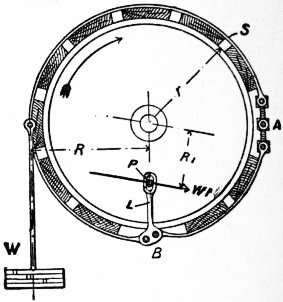
Fig. 1.
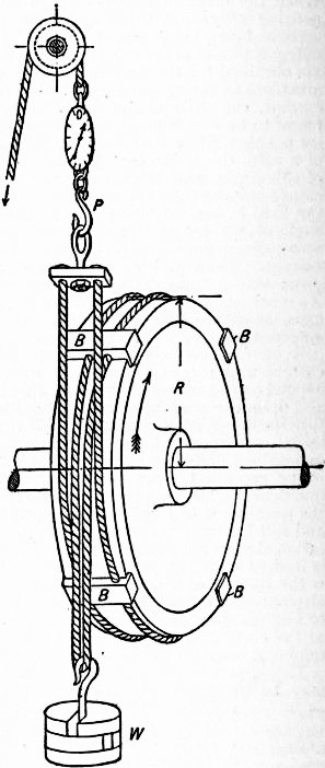
Fig. 2.
Lord Kelvin patented a brake in 1858 (fig. 2) consisting of a rope or cord wrapped round the circumference of a rotating wheel, to one end of which is applied a regulated force, the other end being fixed to a spring balance. The ropes are spaced laterally by the blocks B, B, B, B, which also serve to prevent them from slipping sideways. When the wheel is turning in the direction indicated, the forces holding the band still are W, and p, the observed pull on the spring balance. Both these forces usually act at the same radius R, the distance from the axis to the centre line of the rope, in which case the torque T is (W − p)R, and consequently the brake horse-power is [(W − p)R × 2πN] / 33,000. When μ changes the weight W rises or falls against the action of the spring balance until a stable condition of running is obtained. The ratio W/p is given by eμθ, where e = 2.718; μ is the coefficient of friction and θ the angle, measured in radians, subtended by the arc of contact between the rope and the wheel. In fig. 2 θ = 2π. The ratio W/p increases very rapidly as θ is increased, and therefore, by making θ sufficiently large, p may conveniently be made a small fraction of W, thereby rendering errors of observation of the spring balance negligible. Thus this kind of brake, though cheap to make, is, when θ is large enough, an exceedingly accurate measuring instrument, readily applied and easily controlled. It has come into very general use in recent years, and has practically superseded the older forms of block brakes.
It is sometimes necessary to use water to keep the brake wheel cool. Engines specially designed for testing are usually provided with a brake wheel having a trough-shaped rim. Water trickles continuously into the trough, and the centrifugal action holds it as an inside lining against the rim, where it slowly evaporates.
Fig. 3 shows a band-brake invented by Professor James Thomson, suitable for testing motors exerting a constant torque (see Engineering, 22nd October 1880). To maintain eμθ constant, compensation for variation of μ is made by inversely varying θ. A and B are fast and loose pulleys, and the brake band is placed partly over the one and partly over the other. Weights W and w are adjusted to the torque. The band turns with the fast pulley if μ increase, thereby slightly turning the loose pulley, otherwise at rest, until θ is adjusted to the new value of μ. This form of brake was also invented independently by J.A.M.L. Carpentier, and the principle has been used in the Raffard brake. A self-compensating brake of another kind, by Marcel Deprez, was described with Carpentier’s in 1880 (Bulletin de la société d’encouragement, Paris). W.E. Ayrton and J. Perry used a band or rope brake in which compensation is effected by the pulley drawing in or letting out a part of the band or rope which has been roughened or in which a knot has been tied.
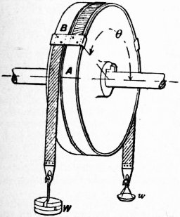
Fig. 3.
In an effective water-brake invented by W. Froude (see Proc. Inst. M. E. 1877), two similar castings, A and B, each consisting of a boss and circumferential annular channel, are placed face to face on a shaft, to which B is keyed, A being free (fig. 4). A ring tube of elliptical section is thus formed. Each channel is divided into a series of pockets by equally spaced vanes inclined at 45°. When A is held still, and B rotated, centrifugal action sets up vortex currents in the water in the pockets; thus a continuous circulation is caused between B and A, and the consequent changes of momentum give rise to oblique reactions. The moments of the components of these actions and reactions in a plane to which the axis of rotation is at right angles are the two aspects of the torque acting, and therefore the torque acting on B through the shaft is measured by the torque required to hold A still. Froude constructed a brake to take up 2000 H.P. at 90 revs. per min. by duplicating this apparatus. This replaced the propeller of the ship whose engines were to be tested, and the outer casing was held from turning by a suitable arrangement of levers carried to weighing apparatus conveniently disposed on the wharf. The torque corresponding to 2000 H.P. at 90 revs. per min. is 116,772 foot-pounds, and a brake 5 ft. in diameter gave this resistance. Thin metal sluices were arranged to slide between the wheel and casing, and by their means the range of action could be varied from 300 H.P. at 120 revs. per min. to the maximum.
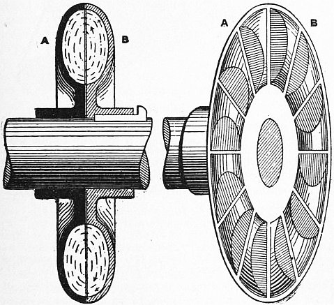
Fig. 4.
Professor Osborne Reynolds in 1887 patented a water-brake (see Proc. Inst. C.E. 99, p. 167), using Froude’s turbine to obtain the highly resisting spiral vortices, and arranging passages in the casing for the entry of water at the hub of the wheel and its exit at the circumference. Water enters at E (fig. 5), and finds its way into the interior of the wheel, A, driving the air in front of it through the air-passages K, K. Then following into the pocketed chambers V1, V2, it is caught into the vortex, and finally escapes at the circumference, flowing away at F. The air-ways k, k, in the fixed vanes establish communication between the cores of the vortices and the atmosphere. From 1⁄5 to 30 H.P. may be measured at 100 revs. per min. by a brake-wheel of this kind 18 in. in diameter. For other speeds the power varies as the cube of the speed. The casing is held from turning by weights hanging on an attached arm. The cocks regulating the water are connected to the casing, so that any tilting automatically regulates the flow, and therefore the thickness of the film in the vortex. In this way the brake may be arranged to maintain a constant torque, not withstanding variation of the speed. In G.I. Alden’s brake (see Trans. Amer. Soc. Eng. vol. xi.) the resistance is obtained by turning a cast iron disk against the frictional resistance of two thin copper plates, which are held in a casing free to turn upon the shaft, and are so arranged that the pressure between the rubbing surfaces is controlled, and the heat developed by friction carried away, by the regulated flow of water through the casing. The torque required to hold the casing still against the action of the disk measures the torque exerted by the shaft to which the disk is keyed.
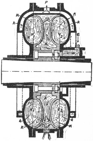
Fig. 5.
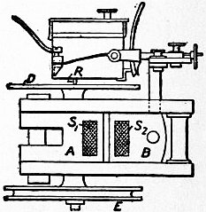
Fig. 6.
Transmission Dynamometers.—The essential part of many transmission dynamometers is a spring whose deformation indirectly measures the magnitude of the force transmitted through it. For many kinds of spring the change of form is practically proportional to the force, but the relation should always be determined experimentally. General A.J. Morin (see Notice sur divers appareils dynamométriques, Paris, 1841), in his classical experiments on traction, arranged his apparatus so that the change in form of the spring was continuously recorded on a sheet of paper drawn under a style. For longer experiments he used a “Compteur” or mechanical integrator, suggested by J.V. Poncelet, from which the work done during a given displacement could be read off directly. This device consists of a roller of radius r, pressed into contact with a disk. The two are carried on a common frame, so arranged that a change in form of the spring causes a relative displacement of the disk and roller, the point of contact moving radially from or towards the centre of the disk. The radial distance x is at any instant proportional to the force acting through the spring. The angular displacement, θ, of the disk is made proportional to the displacement, s, of the point of application of the force by suitable driving gear. If dφ is the angular displacement of the roller corresponding to displacements, dθ of the disk, and ds of the point of application of P, a, and C constants, then dφ = xdθ / r = (a/r) P ds = C·P ds, and therefore φ = C ∫S2S1 P ds; that is, the angular displacement of the roller measures the work done during the displacement from s1 to s2. The shaft carrying the roller is connected to a counter so that φ may be observed. The angular velocity of the shaft is proportional to the rate of working. Morin’s dynamometer is shown in fig. 6. The transmitting spring is made up of two flat bars linked at their ends. Their centres s1, s2, are held respectively by the pieces A, B, which together form a sliding pair. The block A carries the disk D, B carries the roller R and counting gear. The pulley E is driven from an axle of the carriage. In a dynamometer used by F.W. Webb to measure the tractive resistance of trains on the London & North-Western railway, a tractive pull or push compresses two spiral springs by a definite amount, which is recorded to scale by a pencil on a sheet of paper, drawn continuously from a storage drum at the rate of 3 in. per mile, by a roller driven from one of the carriage axles. Thus the diagram shows the tractive force at any instant. A second pencil electrically connected to a clock traces a time line on the diagram with a kick at every thirty seconds. A third pencil traces an observation line in which a kick can be made at will by pressing any one of the electrical pushes placed about the car, and a fourth draws a datum line. The spring of the dynamometer car used by W. Dean on the Great Western railway is made up of thirty flat plates, 7 ft. 6 in. long, 5 in. × 5⁄8 in. at the centre, spaced by distance pieces nibbed into the plates at the centre and by rollers at the ends. The draw-bar is connected to the buckle, which is carried on rollers, the ends of the spring resting on plates fixed to the under-frame. The gear operating the paper roll is driven from the axle of an independent wheel which is let down into contact with the rail when required. This wheel serves also to measure the distance travelled. A Morin disk and roller integrator is connected with the apparatus, so that the work done during a journey may be read off. Five lines are traced on the diagram.
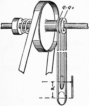
Fig. 7.
In spring dynamometers designed to measure a transmitted torque, the mechanical problem of ascertaining the change of form of the spring is complicated by the fact that the spring and the whole apparatus are rotating together. In the Ayrton and Perry transmission dynamometer or spring coupling of this type, the relative angular displacement is proportional to the radius of the circle described by the end of a light lever operated by mechanism between the spring-connected parts. By a device used by W.E. Dalby (Proc. Inst.C.E. 1897-1898, p. 132) the change in form of the spring is shown on a fixed indicator, which may be placed in any convenient position. Two equal sprocket wheels Q1, Q2, are fastened, the one to the spring pulley, the other to the shaft. An endless band is placed over them to form two loops, which during rotation remain at the same distance apart, unless relative angular displacement occurs between Q1 and Q2 (fig. 7) due to a change in form of the spring. The change in the distance d is proportional to the change in the torque transmitted from the shaft to the pulley. To measure this, guide pulleys are placed in the loops guided by a geometric slide, the one pulley carrying a scale, and the other an index. A recording drum or integrating apparatus may be arranged on the pulley frames. A quick variation, or a periodic variation of the magnitude of the force or torque transmitted through the springs, tends to set up oscillations, and this tendency increases the nearer the periodic time of the force variation approaches a periodic time of the spring. Such vibrations may be damped out to a considerable extent by the use of a dash-pot, or may be practically prevented by using a relatively stiff spring.
Every part of a machine transmitting force suffers elastic deformation, and the force may be measured indirectly by measuring the deformation. The relation between the two should in all cases be found experimentally. G.A. Hirn (see Les Pandynamomètres, Paris, 1876) employed this principle to measure the torque transmitted by a shaft. Signor Rosio used a telephonic method to effect the same end, and mechanical, optical and telephonic devices have been utilized by the Rev. F.J. Jervis-Smith. (See Phil. Mag. February 1898.)
H. Frahm,1 during an important investigation on the torsional vibration of propeller shafts, measured the relative angular displacement of two flanges on a propeller shaft, selected as far apart as possible, by means of an electrical device (Engineering, 6th of February 1903). These measurements were utilized in combination with appropriate elastic coefficients of the material to find the horse-power transmitted from the engines along the shaft to the propeller. In this way the effective horse-power and also the mechanical efficiency of a number of large marine engines, each of several thousand horse-power, have been determined.
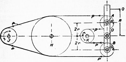
Fig. 8.
When a belt, in which the maximum and minimum tensions are respectively P and p ℔, drives a pulley, the torque exerted is (P − p)r ℔ ft., r being the radius of the pulley plus half the thickness of the belt. P and p may be measured directly by leading the belt round two freely hanging guide pulleys, one in the tight, the other in the slack part of the belt, and adjusting loads on them until a stable condition of running is obtained. In W. Froude’s belt dynamometer (see Proc. Inst. M.E., 1858) (fig. 8) the guide pulleys G1, G2 are carried upon an arm free to turn about the axis O. H is a pulley to guide the approaching and receding parts of the belt to and from the beam in parallel directions. Neglecting friction, the unbalanced torque acting on the beam is 4r {P − p} ℔ ft. If a force Q acting at R maintains equilibrium, QR/4 = (P − p)r = T. Q is supplied by a spring, the extensions of which are recorded on a drum driven proportionally to the angular displacement of the driving pulley; thus a work diagram is obtained. In the Farcot form the guide pulleys are attached to separate weighing levers placed horizontally below the apparatus. In a belt dynamometer built for the Franklin Institute from the designs of Tatham, the weighing levers are separate and arranged horizontally at the top of the apparatus. The weighing beam in the Hefner-Alteneck dynamometer is placed transversely to the belt (see Electrotechnischen Zeitschrift, 1881, 7). The force Q, usually measured by a spring, required to maintain the beam in its central position is proportional to (P − p). If the angle θ1 = θ2 = 120°, Q = (P − p) neglecting friction.
When a shaft is driven by means of gearing the driving torque is measured by the product of the resultant pressure P acting between the wheel teeth and the radius of the pitch circle of the wheel fixed to the shaft. Fig. 9, which has been reproduced from J. White’s A New Century of Inventions (Manchester, 1822), illustrates possibly the earliest application of this principle to dynamometry. The wheel D, keyed to the shaft overcoming the resistance to be measured, is driven from wheel N by two bevel wheels L, L, carried in a loose pulley K. The two shafts, though in a line, are independent. A torque applied to the shaft A can be transmitted to D, neglecting friction, without change only if the central pulley K is held from turning; the torque required to do this is twice the torque transmitted.
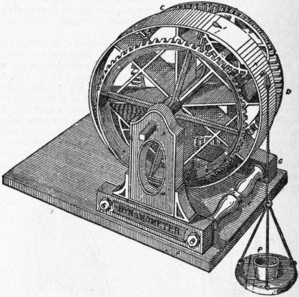
Fig. 9.
The torque acting on the armature of an electric motor is necessarily accompanied by an equal and opposite torque acting on the frame. If, therefore, the motor is mounted on a cradle free to turn about knife-edges, the reacting torque is the only torque tending to turn the cradle when it is in a vertical position, and may therefore be measured by adjusting weights to hold the cradle in a vertical position. The rate at which the motor is transmitting work is then T2πn / 550 H.P., where n is the revolutions per second of the armature.
See James Dredge, Electric Illumination, vol. ii. (London, 1885); W.W. Beaumont, “Dynamometers and Friction Brakes,” Proc. Inst.C.E. vol. xcv. (London, 1889); E. Brauer, “Über Bremsdynamometer and verwandte Kraftmesser,” Zeitschrift des Vereins deutscher Ingenieure (Berlin, 1888); J.J. Flather, Dynamometers and the Measurement of Power (New York, 1893).
(W. E. D.)
1 H. Frahm, “Neue Untersuchungen über die dynamischen Vorgänge in den Wellenleitungen von Schiffsmaschinen mit besonderer Berücksichtigung der Resonanzschwingungen,” Zeitschrift des Vereins deutscher Ingenieure, 31st May 1902.
DYNASTY (Gr. δυναστεία, sovereignty, the position of a δυνάοτης, lord, ruler, from δύνασθαι, to be able, δύναμις, power), a family or line of rulers, a succession of sovereigns of a country belonging to a single family or tracing their descent to a common ancestor. The term is particularly used in the history of ancient Egypt as a convenient means of arranging the chronology.
DYSART, a royal and police burgh and seaport of Fifeshire, Scotland, on the shore of the Firth of Forth, 2 m. N.E. of Kirkcaldy by the North British railway. Pop. (1901) 3562. It has a quaint old-fashioned appearance, many ancient houses in High Street bearing inscriptions and dates. The public buildings include a town hall, library, cottage hospital, mechanics’ institute and memorial hall. Scarcely anything is left of the old chapel dedicated to St Dennis, which for a time was used as a smithy; and of the chapel of St Serf, the patron saint of the burgh, only the tower remains. The chief industries are the manufacture of bed and table linen, towelling and woollen cloth, shipbuilding and flax-spinning. There is a steady export of coal, and the harbour is provided with a wet dock and patent slip. In smuggling days the “canty carles” of Dysart were professed “free traders.” In the 15th and 16th centuries the town was a leading seat of the salt industry (“salt to Dysart” was the equivalent of “coals to Newcastle”), but the salt-pans have been abandoned for a considerable period. Nail-making, once famous, is another extinct industry. During the time of the alliance between Scotland and Holland, which was closer in Fifeshire than in other counties, Dysart became known as Little Holland. To the west of the town is Dysart House, the residence of the earl of Rosslyn. With Burntisland and Kinghorn Dysart forms one of the Kirkcaldy district group of parliamentary burghs. The town is mentioned as early as 874 in connexion with a Danish invasion. Its name is said to be a corruption of the Latin desertum, “a desert,” which was applied to a cave on the seashore occupied by St Serf. In the cave the saint held his famous colloquy with the devil, in which Satan was worsted and contemptuously dismissed. From James V. the town received the rights of a royal burgh. In 1559 it was the headquarters of the Lords of the Congregation, and in 1607 the scene of the meetings of the synod of Fife known as the Three Synods of Dysart. Ravensheugh Castle, on the shore to the west of the town, is the Ravenscraig of Sir Walter Scott’s ballad of “Rosabelle.”
William Murray, a native of the place, was made earl of Dysart in 1643, and his eldest child and heir, a daughter, Elizabeth, obtained in 1670 a regrant of the title, which passed to the descendants of her first marriage with Sir Lionel Tollemache, Bart., of Helmingham; she married secondly the 1st duke of Lauderdale, but had no children by him, and died in 1698. This countess of Dysart (afterwards duchess of Lauderdale) was a famous beauty of the period, and notorious both for her amours and for her political influence. She was said to have been the mistress of Oliver Cromwell, and also of Lauderdale before her first husband’s death, and was a leader at the court of Charles II. Wycherley is supposed to have aimed at her in his Widow Blackacre in the Plain Dealer. Her son, Lionel Tollemache (d. 1727), transmitted the earldom to his grandson Lionel (d. 1770), whose sons Lionel (d. 1799) and Wilbraham (d. 1821) succeeded; they died without issue, and their sister Louisa (d. 1840), who married John Manners, an illegitimate son of the second son of the 2nd duke of Rutland, became countess in her own right, being succeeded by her grandson (d. 1878), and his grandson, the 8th earl.
The earldom of Dysart must not be confounded with that of Desart (Irish), created (barony 1733) in 1793, and held in the Cuffe family, who were originally of Creech St Michael, Somerset, the Irish branch dating from Queen Elizabeth’s time.
DYSENTERY (from the Gr. prefix δυσ-, in the sense of “bad,” and ἔντερον, the intestine), also called “bloody flux,” an infectious disease with a local lesion in the form of inflammation and ulceration of the lower portion of the bowels. Although at one time a common disease in Great Britain, dysentery is now very rarely met with there, and is for the most part confined to warm countries, where it is the cause of a large amount of mortality. (For the pathology see Digestive Organs.)
Recently considerable advance has been made in our knowledge of dysentery, and it appears that there are two distinct types of the disease: (1) amoebic dysentery, which is due to the presence of the amoeba histolytica (of Schaudinn) in the intestine; (2) bacillary dysentery, which has as causative agent two separate bacteria, (a) that discovered by Shiga in Japan, (b) that discovered by Flexner in the Philippine Islands. With regard to the bacillary type, at first both organisms were considered to be identical, and the name bacillus dysenteriae was given to them; but later it was shown that these bacilli are different, both in regard to their cultural characteristics and also in that one (Shiga) gives out a soluble toxin, whilst the other has so far resisted all efforts to discover it. Further, the serum of a patient affected with one of the types has a marked agglutinative power on the variety with which he is infected and not on the other.
Clinically, dysentery manifests itself with varying degrees of intensity, and it is often impossible without microscopical examination to determine between the amoebic and bacillary forms. In well-marked cases the following are the chief symptoms. The attack is commonly preceded by certain premonitory indications in the form of general illness, loss of appetite, and some amount of diarrhoea, which gradually increases in severity, and is accompanied with griping pains in the abdomen (tormina). The discharges from the bowels succeed each other with great frequency, and the painful feeling of pressure downwards (tenesmus) becomes so intense that the patient is constantly desiring to defecate. The matters passed from the bowels, which at first resemble those of ordinary diarrhoea, soon change their character, becoming scanty, mucous or slimy, and subsequently mixed with, or consisting wholly of, blood, along with shreds of exudation thrown off from the mucous membrane of the intestine. The evacuations possess a peculiarly offensive odour characteristic of the disease. Although the constitutional disturbance is at first comparatively slight, it increases with the advance of the disease, and febrile symptoms come on attended with urgent thirst and scanty and painful flow of urine. Along with this the nervous depression is very marked, and the state of prostration to which the patient is reduced can scarcely be exceeded. Should no improvement occur death may take place in from one to three weeks, either from repeated losses of blood, or from gradual exhaustion consequent on the continuance of the symptoms, in which case the discharges from the bowels become more offensive and are passed involuntarily.
When, on the other hand, the disease is checked, the signs of improvement are shown in the cessation of the pain, in the evacuations being less frequent and more natural, and in relief from the state of extreme depression. Convalescence is, however, generally slow, and recovery may be imperfect—the disease continuing in a chronic form, which may exist for a variable length of time, giving rise to much suffering, and not unfrequently leading to an ultimately fatal result.
The dysentery poison appears to exert its effects upon the glandular structures of the large intestine, particularly in its lower part. In the milder forms of the disease there is simply a congested or inflamed condition of the mucous membrane, with perhaps some inflammatory exudation on its surface, which is passed off by the discharges from the bowels. But in the more severe forms ulceration of the mucous membrane takes place. Commencing in and around the solitary glands of the large intestine in the form of exudations, these ulcers, small at first, enlarge and run into each other, till a large portion of the bowel may be implicated in the ulcerative process. Should the disease be arrested these ulcers may heal entirely, but occasionally they remain, causing more or less disorganization of the coats of the intestines, as is often found in chronic dysentery. Sometimes, though rarely, the ulcers perforate the intestines, causing rapidly fatal inflammation of the peritoneum, or they may erode a blood vessel and produce violent haemorrhage. Even where they undergo healing they may cause such a stricture of the calibre of the intestinal canal as to give rise to the symptoms of obstruction which ultimately prove fatal. One of the severest complications of the disease is abscess of the liver, usually said to be solitary, and known as tropical abscess of the liver, but probably is more frequently multiple than is usually thought.
Treatment.—Where the disease is endemic or is prevailing epidemically, it is of great importance to use all preventive measures, and for this purpose the avoidance of all causes likely to precipitate an attack is to be enjoined. Exposure to cold after heat, the use of unripe fruit, and intemperance in eating and drinking should be forbidden; and the utmost care taken as to the quality of the food and drinking water. In houses or hospitals where cases of the disease are under treatment, disinfectants should be freely employed, and the evacuations of the patients removed as speedily as possible, having previously been sterilized in much the same manner as is employed in typhoid fever. In the milder varieties of this complaint, such as those occurring sporadically, and where the symptoms are probably due to matters in the bowels setting up the dysenteric irritation, the employment of diaphoretic medicines is to be recommended, and the administration of such a laxative as castor oil, to which a small quantity of laudanum has been added, will often, by removing the source of the mischief, arrest the attack; but a method of treatment more to be recommended is the use of salines in large doses, such as one drachm of sodium sulphate from four to eight times a day. This treatment may with advantage be combined with the internal administration of ipecacuanha, which still retains its reputation in this disease. Latterly, free irrigation of the bowel with astringents, such as silver nitrate, tannalbin, &c., has been attended with success in those cases which have been able to tolerate the injections. In many instances they cannot be used owing to the extreme degree of irritability of the bowel. The operation of appendicostomy, or bringing the appendix to the surface and using it as the site for the introduction of the irrigating fluid, has been attended with considerable success.
In those cases due to Shiga’s bacillus the ideal treatment has been put at our disposal by the preparation of a specific antitoxin; this has been given a trial in several grave epidemics of late, and may be said to be the most satisfactory treatment and offer the greatest hope of recovery. It is also of great use as a prophylactic.
The preparations of morphia are of great value in the symptomatic treatment of the disease. They may be applied externally as fomentations, for the relief of tormina; by rectal injection for the relief of the tenesmus and irritability of the bowel; hypodermically in advanced cases, for the relief of the general distress. In amoebic dysentery, warm injections of quinine per rectum have proved very efficacious, are usually well tolerated, and are not attended with any ill effects. The diet should be restricted, consisting chiefly of soups and farinaceous foods; more especially is this of importance in the chronic form. For the thirst ice may be given by the mouth. Even in the chronic forms, confinement to bed and restriction of diet are the most important elements of the treatment. Removal from the hot climate and unhygienic surroundings must naturally be attended to.
Bibliography.—Allbutt and Rolleston, System of Medicine, vol. ii. part ii. (1907), “Dysentery,” Drs Andrew Davidson and Simon Flexner; Davidson, Hygiene and Diseases of Warm Climates (Edinburgh, 1903); Fearnside in Ind. Med. Gaz. (July 1905); Ford in Journal of Tropical Medicine (July 15, 1904); Korentchewsky in Bulletin de l’Institut Pasteur (February 1905); Shiga: Osier and M’Crae’s System of Medicine, vol. ii. p. 781 (1907); Skschivan and Stefansky in Berliner klinische Wochenschrift (February 11, 1907); Vaillard and Dopter, on the treatment by antidysenteric serum, Annales de l’Institut Pasteur, No. 5, p. 326 (1906); J.A. Pottinger, “Appendicostomy in Chronic Dysentery,” Lancet (December 28, 1907); Robert Doerr, Das Dysenterietoxin (Gustav Fischer, Jena, 1907); F.M. Sandwith, “Hunterian Lecture on the Treatment of Dysentery,” Lancet (December 7, 1907).
DYSPEPSIA (from the Gr. prefix δυσ-, hard, ill, and πέπτειν, to digest), or indigestion, a term vaguely given to a group of pathological symptoms. There are comparatively few diseases of any moment where some of the phenomena of dyspepsia are not present as associated symptoms, and not infrequently these exist to such a degree as to mask the real disease, of which they are only complications. This is especially the case in many organic diseases of the alimentary canal, in which the symptoms of dyspepsia are often the most prominent. In its restricted meaning, however (and it is to this that the present article applies), the term is used to describe a functional derangement of the natural process of digestion, apart from any structural change in the organs concerned in the act.
The causes of this trouble may be divided into (a) those which concern the food, and (b) those which concern the organism. Among the causes connected with the food are not only the indulgence in indigestible articles of diet, but the too common practice of eating too much of what may be otherwise quite wholesome and digestible; and irregular, too frequent or too infrequent meals. The quantity of food required by different individuals varies between wide limits, but also the quantity required by the same individual varies considerably according to circumstances, more food being needed in cold than in warm weather, and more in an active open-air occupation than in a sedentary one. The thorough mastication of the food is a very important precursor of digestion,1 and this only too often fails, either owing to haste over meals or because of painful or deficient teeth. Again, the quality of the food is of importance, some kinds of flesh being harder and more difficult of mastication than others. This is especially the case with meat that has been smoked or salted, and with that cooked too soon after the death of the animal. Drinks are a common source of dyspepsia. Beer when new and its fermentation not completed is especially bad. Vinegar and acid wines, if taken in large quantities, tend to produce gastric catarrh, and tea is a very fruitful source of this trouble. Even too much water at meal-times may cause indigestion, since the food in the mouth is apt to be softened by the water instead of saliva, and also the gastric juice becomes unduly diluted, rendering the digestion in the stomach too slow and prolonged. Carious teeth and oral sepsis, from whatsoever cause, lead to the same trouble.
Of the causes which concern the organism, nervous influences come first. Bad news may take away all power of digestion and even provoke vomiting, and any worry or mental trouble tends to bring on this condition. General weakness and atony of the body affects the stomach in like degree, and, if the muscles of the abdominal wall be much wasted, they become too weak to support the abdominal viscera in place. Hence results a general tendency for these organs to fall, giving rise to a condition of visceroptosis, of which an obstinate dyspepsia is a very marked feature. Adhesions of the intestines from old inflammatory troubles, floating kidney and bad circulation may each be a cause of painful digestion. Again, a dyspepsia that will not yield to treatment is often one of the symptoms of renal disease, or, in young people of fifteen to twenty years of age, it may be the earliest sign of a gouty diathesis, or even of a more serious condition still—incipient phthisis. Chronic dyspepsia, by weakening the organism, renders it more liable to fall a prey to the attacks of the tubercle bacillus, but, on the other hand, the tuberculous lesion in the lung is often accompanied by a most intractable form of dyspepsia. From this it is clear that any condition which lessens the general well-being of the organism as a whole, apart from its producing any permanent morbid condition in the stomach, may yet interfere with the normal digestive processes and so give rise to dyspepsia.
The symptoms of dyspepsia, even when due to a like cause, are so numerous and diversified in different individuals that probably no description could exactly represent them as they occur in any given case. All that can be here attempted is to mention some of the more prominent morbid phenomena usually present in greater or less degree.
Very briefly, a furred tongue, foul breath, disturbance of appetite, nausea and vomiting, oppression in the chest, pain, flatulence and distension, acidity, pyrosis and constipation or diarrhoea are a few of the commonest symptoms.
When the attack is dependent on some error in diet, and the dyspepsia consequently more of an acute character, there is often pain followed with sickness and vomiting of the offensive matters, after which the patient soon regains his former healthy state. What are commonly known as “bilious attacks” are frequently of this character. In the more chronic cases of dyspepsia the symptoms are somewhat different. A sensation of discomfort comes on shortly after a meal, and is more of the nature of weight and distension in the stomach than of actual pain, although this too may be present. These feelings may come on after each meal, or only after certain meals, and they may arise irrespective of the kind of food taken, or only after certain articles of diet. As in most of such cases the food is long retained in the stomach, it is apt to undergo fermentive changes, one of the results of which is the accumulation of gases which cause flatulence and eructations of an acid or foul character. Occasionally quantities of hot, sour, tasteless or bitter fluid—pyrosis—or mouthfuls of half-digested food, regurgitate from the stomach. Temporary relief may be obtained when another meal is taken, but soon the uncomfortable sensations return as before. The appetite may be craving or deficient, or desirous of abnormal kinds of food. The tongue registers the gastric condition with great delicacy;—a pasty white fur on the tongue is considered a sign of weakness or atony of the digestive tract; a clean pointed tongue with large papillae, and rather red at the edges and tip, is a sign of gastric irritation; and a pale flabby tongue suggests the need of stimulating treatment. Constipation is more common in the chronic forms of dyspepsia, diarrhoea in the acute.
Numerous disagreeable and painful sensations in other parts are experienced, and are indeed often more distressing than the merely gastric symptoms. Pains in the chest, shortness of breathing, palpitation, headache, giddiness, affections of vision, coldness of the extremities, and general languor are common accompaniments of dyspepsia; while the nervous phenomena are specially troublesome in the form of sleeplessness, irritability, despondency and hypochondriasis.
As regards treatment only a few general observations can be made. The careful arrangement of the diet is a matter of first importance. Quantity must be regulated by the digestive capabilities of the individual, his age, and the demands made upon his strength by work. There is little doubt that the danger is in most instances on the side of excess, and the rule which enjoins the cessation from eating before the appetite is satisfied is a safe one for dyspeptics. Due time, too, must be given for the digestion of a meal, and from four to six hours are in general required for this purpose. Long fasts, however, are nearly as hurtful as too frequent meals. Of no less importance is the kind of food taken, and on this point those who suffer from indigestion must ever exercise the greatest care. It must be borne in mind that idiosyncrasy often plays an important part in digestion, some persons being unable to partake without injury of substances which are generally regarded as wholesome and digestible. In most cases it is found very helpful to separate the protein from the farinaceous food, and the more severe the dyspepsia the more thoroughly should this be done, only relaxing as the dyspepsia yields. No fluid should be drunk at meal-times, but from one to two tumblers of hot water should be drunk from an hour to an hour and a half before food. This washes any remnant of the last meal from the stomach, and also supplies material for the free secretion of saliva and gastric juice, thus promoting and accelerating digestion. The only exception to this is in the case of a dilated stomach, when it is wholly contra-indicated. With regard to mastication, Sir Andrew Clark’s rule is a very good one, and is more easily followed than the ideal theory laid down by Horace Fletcher, according to whom any food is digestible if properly treated while still in the mouth. Clark’s rule is that as the mouth normally contains thirty-two teeth, thirty-two bites should be given before the food is swallowed. This, of course, is a practical doctor’s concession to human weakness. Mr Fletcher would train every one to “chew” till the contents of the mouth were swallowed by reflex action without deliberate act; and he applies this theory of mastication and salivation also to drinks (except water). Again, a lack of warmth being a source of dyspepsia, this should be attended to, the back of the neck, the front of the abdomen and the feet being the parts that require special attention. The feet should be raised on a stool, the ankles protected with warm stockings and a woollen “cummerbund” wound two or three times round the body. Experience has shown that in this complaint no particular kind of food or avoidance of food is absolutely to be relied on, but that in general the best diet is one of a mixed animal and vegetable kind, simply but well cooked. The partaking of many dishes, of highly-seasoned or salted meats, raw vegetables, newly-baked bread, pastry and confectionery are all well-known common causes of dyspepsia, and should be avoided. When even the simple diet usually taken is found to disagree, it may be necessary to change it temporarily for a still lighter form, such as a milk diet, and that even in very moderate quantity.
The employment of alcoholic stimulants to assist digestion is largely resorted to, both with and without medical advice. While it seems probable that in certain cases of atonic dyspepsia, particularly in the feeble and aged, the moderate administration of alcohol has the effect of stimulating the secretion of gastric juice, and is an important adjuvant to other remedies, the advantages of its habitual use as an aid to digestion by the young and otherwise healthy, is more than questionable, and it will generally be found that among them, those are least troubled with indigestion who abstain from it. Rest should be taken both before and after food, and general hygienic measures are highly important, since whatever improves the state of the health will have a favourable influence on digestion. Hence regular exercise in the open air, early rising and the cold bath are to be strongly recommended.
The medicinal treatment of dyspepsia can only be undertaken by a physician, but the following is a very brief résumé of the drugs he depends on to-day. Bicarbonate of soda with some bitter, as quassia, gentian or columba, is much in vogue as a direct gastric stimulant. In irritable dyspepsia some form of bismuth in solution or powder; and, to assist digestion through the nervous system, nux vomica and strychnine can be relied on. To give directly digestive material, hydrochloric acid, pepsin and rennet are prescribed in many forms, but where there is much vomiting ingluvin is more efficacious than pepsin. When farinaceous food is badly borne, diastase is helpful, given either before or with the meal. To prevent fermentation, phenol, creasote and sulpho-carbolate of soda are all extremely useful in skilled hands; and for intestinal decomposition and flatulent distension, bismuth salicylate with salol or β-naphthol is much used. Cyllin, and charcoal in many forms, may be taken both for gastric and intestinal flatulence. But all these drugs, of proved value though they are, must be modified and combined to suit the special idiosyncrasy of the patient, and are therefore often worse than useless in inexperienced hands. The condition of the bowels must always have due attention.
See also Digestive Organs; Nutrition and Dietetics.
1 This aspect of the matter—“buccal digestion”—has been specially emphasized in recent years by Horace Fletcher of the United States, whose experience of the results of systematic “chewing,” confirmed by Sir M. Foster, Prof. Chittenden and others, has almost revolutionized the science of dietetics.
DYSTELEOLOGY, a modern word invented by Haeckel (Evolution of Man) for the doctrine of purposelessness, as opposed to the philosophical doctrine of design (Teleology).
DZUNGARIA, Dsongaria, or Jungaria, a former Mongolian kingdom of Central Asia, raised to its highest pitch by Kaldan or Bushtu Khan in the latter half of the 17th century, but completely destroyed by Chinese invasion about 1757-1759. It has played an important part in the history of Mongolia and the great migrations of Mongolian stems westward. Now its territory belongs partly to the Chinese empire (east Turkestan and north-western Mongolia) and partly to Russian Turkestan (provinces of Semiryechensk and Semipalatinsk). It derived its name from the Dsongars, or Songars, who were so called because they formed the left wing (dson, left; gar, hand) of the Mongolian army. Its widest limit included Kashgar, Yarkand, Khotan, the whole region of the T’ien Shan, or Tian-shan, Mountains, and in short the greater proportion of that part of Central Asia which extends from 35° to 50° N. and from 72° to 97° E. The name, however, is more properly applied only to the present Chinese province of T’ien Shan-pei-lu and the country watered by the Ili. As a political or geographical term it has practically disappeared from the map; but the range of mountains stretching north-east along the southern frontier of the Land of the Seven Streams, as the district to the south-east of the Balkhash Lake is called, preserves the name of Dzungarian Range.
E The fifth symbol in the English alphabet occupies also the same position in Phoenician and in the other alphabets descended from Phoenician. As the Semitic alphabet did not represent vowels, E was originally an aspirate. Its earliest form, while writing is still from right to left, is , the upright being continued some distance below the lowest of the cross-strokes. In some of the Greek alphabets it appears as with the upright prolonged at both top and bottom, but it soon took the form with which we are familiar, though in the earlier examples of this form the cross-strokes are not horizontal but drop at an angle, . In Corinth and places under its early influence like Megara, or colonized from it like Corcyra, the symbol for e takes the form or , while at Sicyon in the 6th and 5th centuries B.C. it is represented by . In early Latin it was sometimes represented by two perpendicular strokes of equal length, .


In the earliest Greek inscriptions and always in Latin the symbol represented both the short and the long e-sound. In Greek also it was often used for the close long sound which arose either by contraction of two short e-sounds or by the loss of a consonant, after a short e-sound, as in φιλεῖτε, “you love,” for φιλέετε, and φαεινός, “bright,” out of an earlier φαεσνός. The Ionian Greeks of Asia Minor, who had altogether lost the aspirate, were the first to use the symbol for the long e-sound, and in official documents at Athens down to 403 B.C., when the Greek alphabet as still known was adopted by the state, represented ε, η and the sound arising by contraction or consonant loss as mentioned above which henceforth was written with two symbols, ει, and being really a single sound is known as the “spurious diphthong.” There were some minor distinctions in usage of the symbols and which need not here be given in detail. The ancient Greek name was εἶ, not Epsilon as popularly supposed; the names of the Greek letters are given from Kallias, an earlier contemporary of Euripides, in Athenaeus x. p. 453 d.


In Greek the short e-sound to which was ultimately limited was a close sound inclining more towards i than a; hence the representation of the contraction of εε by ει. Its value in Latin was exactly the opposite, the Latin short e being open, and the long close. In English there has been a gradual narrowing of the long vowels, ā becoming approximately ēi and ē becoming ī (Sweet, History of English Sounds, §§ 781, 817 ff. 2nd ed.). In languages where the diphthong ai has become a monophthong, the resulting sound is some variety of long e. Often the gradual assimilation can be traced through the intermediate stage of ae to ē, as in the Old Latin aidilis, which in classical Latin is aedilis, and in medieval MSS. edilis.
The variety of spelling in English for the long and short e-sounds is conveniently illustrated in Miss Soames’s Introduction to the Study of Phonetics, pp. 16 and 20.
(P. Gi.)
EA (written by means of two signs signifying “house” and “water”), in the Babylonian religion, originally the patron deity of Eridu, situated in ancient times at the head of the Persian Gulf, but now, by reason of the constant accumulation of soil in the Euphrates valley, at some distance from the gulf. Eridu, meaning “the good city,” was one of the oldest settlements in the Euphrates valley, and is now represented by the mounds known as Abu Shahrein. In the absence of excavations on that site, we are dependent for our knowledge of Ea on material found elsewhere. This is, however, sufficient to enable us to state definitely that Ea was a water-deity, and there is every reason to believe that the Persian Gulf was the body of water more particularly sacred to him. Whether Ea (or A-e as some scholars prefer) represents the real pronunciation of his name we do not know. All attempts to connect Ea with Yah and Yahweh are idle conjectures without any substantial basis. He is figured as a man covered with the body of a fish, and this representation, as likewise the name of his temple E-apsu, “house of the watery deep,” points decidedly to his character as a god of the waters (see Oannes). Of his cult at Eridu, which reverts to the oldest period of Babylonian history, nothing definite is known beyond the fact that the name of his temple was E-saggila, “the lofty house”—pointing to a staged tower as in the case of the temple of Bel (q.v.) at Nippur, known as E-Kur, i.e. “mountain house”—and that incantations, involving ceremonial rites, in which water as a sacred element played a prominent part, formed a feature of his worship. Whether Eridu at one time also played an important political rôle is not certain, though not improbable. At all events, the prominence of the Ea cult led, as in the case of Nippur, to the survival of Eridu as a sacred city, long after it had ceased to have any significance as a political centre. Myths in which Ea figures prominently have been found in Assur-bani-pal’s library, indicating that Ea was regarded as the protector and teacher of mankind. He is essentially a god of civilization, and it was natural that he was also looked upon as the creator of man, and of the world in general. Traces of this view appear in the Marduk epic celebrating the achievements of this god, and the close connexion between the Ea cult at Eridu and that of Marduk also follows from two considerations: (1) that the name of Marduk’s sanctuary at Babylon bears the same name, E-saggila, as that of Ea in Eridu, and (2) that Marduk is generally termed the son of Ea, who derives his powers from the voluntary abdication of the father in favour of his son. Accordingly, the incantations originally composed for the Ea cult were re-edited by the priests of Babylon and adapted to the worship of Marduk, and, similarly, the hymns to Marduk betray traces of the transfer of attributes to Marduk which originally belonged to Ea.
It is, however, more particularly as the third figure in the triad, the two other members of which were Anu (q.v.) and Bel (q.v.), that Ea acquires his permanent place in the pantheon. To him was assigned the control of the watery element, and in this capacity he becomes the shar apsi, i.e. king of the Apsu or “the deep.” The Apsu was figured as an ocean encircling the earth, and since the gathering place of the dead, known as Arālu, was situated near the confines of the Apsu, he was also designated as En-Ki, i.e. “lord of that which is below,” in contrast to Anu, who was the lord of the “above” or the heavens. The cult of Ea extended throughout Babylonia and Assyria. We find temples and shrines erected in his honour, e.g. at Nippur, Girsu, Ur, Babylon, Sippar and Nineveh, and the numerous epithets given to him, as well as the various forms under which the god appears, alike bear witness to the popularity which he enjoyed from the earliest to the latest period of Babylonian-Assyrian history. The consort of Ea, known as Damkina, “lady of that which is below,” or Nin-Ki, having the same meaning, or Damgal-nunna, “great lady of the waters,” represents a pale reflection of Ea and plays a part merely in association with her lord.