DESCRIPTION OF PLATES.
Reading edition
DESCRIPTION of the PLATES, as they are mentioned in the Work.
Plate I. INCHKEITH LIGHT-HOUSE.
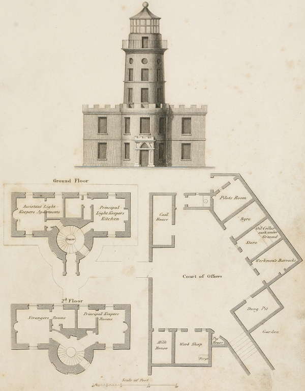
INCH KEITH LIGHT HOUSE.
Drawn by W. Lorimer
PLATE I.
The Light-house of Inchkeith, delineated on Plate I. was erected while Mr Thomas Smith, the writer’s predecessor, held the situation of Engineer for the Northern Light-houses. A plan of it is given, as having been the first of these establishments erected upon the new principle; the Reflectors being illuminated with Argand-burners; the Light-room rendered completely fire-proof; and the Dwelling-house fitted for the accommodation of two keepers. But as this establishment is described in the introductory chapter, at page 24, and the names of the several apartments are marked upon the Plate, it seems unnecessary here to enter into detail.
Plate II. CARR ROCK BEACON.
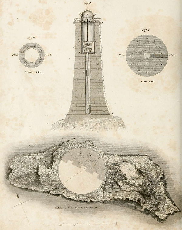
CARR ROCK BEACON as designed in the year 1810.
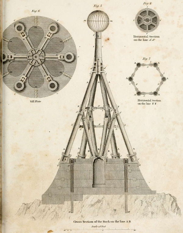
CARR ROCK BEACON as executed in the year 1821.
Drawn by J. Slight
Engd. by E. Mitchell
PLATE II.
Pl. II.
The Carr Rock Beacon is represented in Plate II. and referred to in the introduction at page 53. The diagram marked Figure 1. is an outline of the rock, shewing the position of the beacon, and plan of the first course of the building, made to a radius of nine feet, cut in a dove-tailed form, after the manner of the courses of the Edystone and Bell Rock Light-houses.
Figure 2. is a section of the rock on the line A, B, Fig. 1. with a perpendicular section also of a tower of masonry and apparatus, for tolling an alarm-bell, which was originally intended for this situation. In Fig. 2. letter a represents an aperture measuring 3 inches in diameter, which was perforated with much labour and care through a block of granite 7 feet in length, previously to its being laid. This canal was intended to admit the tidal-waters into the interior chamber of the building marked b, in which the flood-tide was to act upon an air-tight copper-tank, marked c, and its rod of connection formed into a rack with teeth, by which motion was to be given to a train of machinery, represented at d in the void of the building. The machine was to act on the vertical shaft e, connected with a series of hammers f, placed under the great bell g, which was to have measured 5 feet in diameter, and become the cupola or roof of the building. In this manner the bell was to be tolled to forewarn the mariner of his approach to the dangers of the Carr, and the other extensive ledges of sunken rocks in its neighbourhood. By the rise of the flood-tide, and consequent admission of the waters into the canal a, the tank c, with its connecting rod, not only lifted the bell-hammers f, and, at the same time, also elevated the weight marked h, which, in its descent during ebb-tide, was to have continued the motion of the machinery; and thus, by the alternate operation of the tides, the continual tolling of the Bell was to have been preserved.
It will further be seen from the section of this building, that the masonry of the solid is connected perpendicularly by means of stone-joggles inserted half into the one course and half into the other. But in the void or upper part, instead of the joggles, the bed-joints of the stones were let or sunk about an inch in depth, into each other, as at the Bell Rock, forming so many bands or girths to the work. This will be observed by narrowly examining the section at letter i, with its accompanying diagram Fig. 3., which represents a plan of one of the courses of the void, shewing how the stones were connected horizontally by a system of dove-tailing, as is further represented in Fig. 4., being a plan of a course at the level a, k, in which the perforation is delineated for the admission of the tidal-waters.
The ascent to this building was to have been by means of a ladder of cast-iron or flight of steps, marked a, i, l, fixed on the outward wall by means of screw-bolts fixed into brass-bats, sunk into the masonry, and run up with lead. The entrance-door of this building was formed in the cast-iron frame or pedestal on which the great bell was to have been supported, the access to the interior being by the balcony, round which a cast-iron rail was intended, not only for the safety of the keepers or occasional attendants, but also, in some measure, to defend the bell from the sprays of the sea.
Figure 5. represents the Pillar-formed Beacon, as finished at the Carr Rock in the year 1821. The lower part of this diagram is a perpendicular section of the rock on the line A B, Fig. 1. The masonry is also shewn with two of the six great malleable iron-bats or stancheons marked a in Fig. 5., which passing through the several courses, are sunk about 30 inches into the Rock. The upper part of this diagram represents a frame of cast-iron work, of great strength, fashioned somewhat after the manner of what seamen term a spar or spur beacon, from being made generally of timber, set up in the form of struts or spur-beams. The connection of this frame will be understood from the detached diagram Fig. 6., taken upon the line or level marked b in Fig. 5. From Figs. 5. and 6. it will be observed, that the beacon consists of 6 pipes or hollow tubes, marked letter A, which are inserted into the sockets c, in the sill-plate of Fig. 6, into which these hollow tubes are strongly wedged and keyed with culter or spear bolts, which pass through each of the sockets and base of the hollow tubes at c. Besides the main hollow tubes marked A, other six marked B, are set up as spurs or diagonals, which radiate from sockets cast in the centre of the sill-plate marked e. These diagonals are so situated, and connected by dove-tail or hook-joints, that they butt against the main tubes, and support them at f. The main tubes are further connected by means of horizontal bars of malleable iron, marked g in Fig. 5, laid into grooves formed in the arms of the cast-iron collars F, k, which clasp around the main tubes at these points, immediately above and below their connection with the diagonal tubes. These collars are also keyed with the main tubes by means of spear-bolts. At the point of junction d d, towards the top, the main tubes form segments of a common circle, and rest upon the centre block h, into which they are keyed and wedged. As a further security, a strong cast-iron tubular formed case, marked i i, is made to clasp around the whole upper parts of the main tubes at their point of junction d d, so as to form a girth to them. This tubular case or cap i i, is 8 feet in length, and terminates with a cast-iron ball marked m m, which is 3½ feet in diameter, formed into ribs, connected with the cap i i, by means of a socket, through which a spear-bolt passes, and binds it to the top of the tubular-case at the point l.
Fig. 6. represents the Ballast-plate, which forms the sill or basement of the superstructure. It contains about 8 tons of cast-iron, and is so constructed as to become a cap or girth to the upper course of the masonry which it is calculated to secure, by means of a flange of 6 inches in depth at the outward extremity, marked b b in Fig. 5, where it is let into the stone. This plate is cast in six pieces, connected together at the points m m m m m m, by means of screw-bolts of one and a half inch in diameter (with nuts), passing through flanges raised at the joints of its several compartments. At the points n n n n n n, there were six socket-holes, for the reception of the great stancheons or bolts, marked a a, Fig. 5, which, passing through the masonry, are sunk 30 inches into the Rock, where they are fixed at the lower ends with iron-wedges, driven home by means of a long iron-driver. The ballast-plate is connected with the upper ends of these great stancheons, by means of a shackle and bolt, in such a manner that the more exposed parts may be renewed. The whole is imbedded and run up with pozzolano-mortar, so as to preserve the several parts as much as possible from the effects of oxidation.
Fig. 7. represents a horizontal section of this beacon, on the line F F, shewing the connection of the horizontal malleable iron-bars or braces g g g g, which fit into the grooves of the arms of the collars, embracing the hollow tubes or pillars A A A A, and connecting them by means of spear-bolts at k k k k. The grooves in these arms are so formed as to command the braces, and to contain a quantity of Parker’s or Roman cement, by which the bolts are preserved from the effects of oxidation. These collars and arms, with their connecting malleable iron-bars, form a girth immediately above the diagonal struts or braces B B B, Fig. 5. A similar chain of connection is in like manner formed below the junction of these diagonal struts, with the main tubes, which, like those described above, has the effect of binding the whole fabric horizontally.
Fig. 8. is a horizontal section upon the line d d, delineated upon a scale of double the size of the other parts of the beacon, shewing the connection of the hollow tubes A A A A A A, at the top, where they change their cylindrical form into segments of a circle at the point of contact, so as to embrace the centre-block h h. The top of these tubes thus formed into a compact figure, is cased or covered with the cylindrical cap i i, through which the spear-bolts immediately above and below the points d d, in Fig. 5, are made to pass and bind the whole firmly together.
Plate III. GENERAL CHART, SHEWING THE RELATIVE POSITION OF THE BELL ROCK.
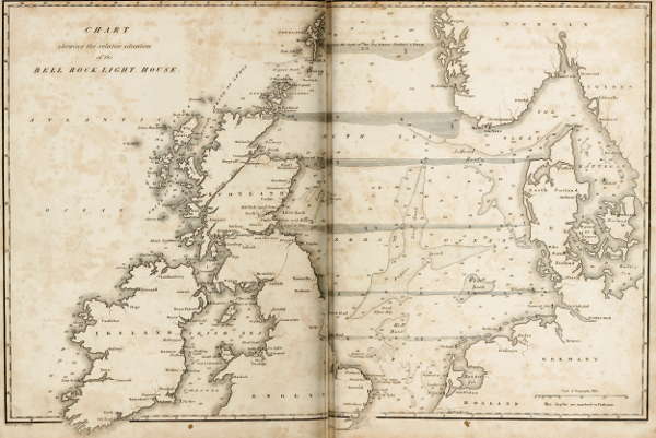
CHART shewing the relative situation of the BELL ROCK LIGHT HOUSE.
Drawn by J. Steedman
Engd. by W. H. Lizars
Plate III.
Pl. III.
This Plate is reduced from a manuscript-map in the possession of the writer, which is drawn upon a large scale, originally intended for exhibiting the depths of the German Ocean or North Sea, and the situations of the numerous Light-houses on the coasts of the United Kingdom, and opposite Continent, but is here given with the view of shewing the relative position of the Bell Rock.
The chief peculiarity of this map is the sectional lines, exhibiting at one view the relative depths of the ocean, in connection with a theory which the writer has advanced, regarding the wasting of the firm ground by the effects of the sea, as alluded to in Appendix V. These sectional lines, of a deeper shade, are drawn across the German Ocean, from shore to shore. As, for example, between Shetland and Norway, the greatest depth is ascertained to be about 140 fathoms, and so of other examples, extending southward as far as the Straits of Dover. The soundings are all marked in fathoms, and, in so far as regards the east coast of Scotland, have been very generally made from on board of the vessels belonging to the service of the Northern Lights. The forms given to the principal sand-banks, and the soundings in the central and eastern parts of this great basin, have been taken from the best maritime surveys, and nautical authorities. The numerous Light-houses on the respective coasts are coloured; those of Scotland being blue, England red, Ireland green, and the foreign Lights yellow.
Plate IV. CHART, SHEWING THE PARTICULAR POSITION OF THE BELL ROCK.
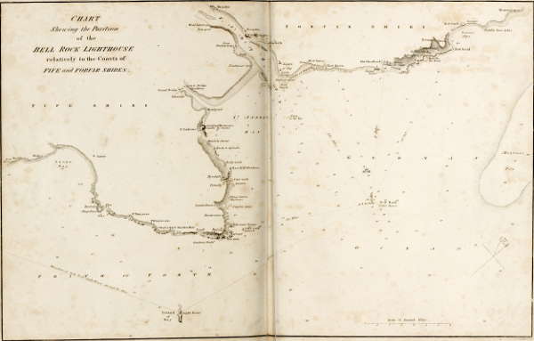
CHART Shewing the Position of the BELL ROCK LIGHTHOUSE relatively to the Coasts of FIFE and FORFAR SHIRES.
Drawn by A. Stevenson
Engd. by W. H. Lizars
PLATE IV.
Pl. IV.
This chart is intended to shew the position of the Rock in reference to the opposite shores of Fife and Forfar, and to the entrances to the Friths of Forth and Tay. The most contiguous point of land, being in the immediate neighbourhood of Aberbrothwick, is distant about 11¾ miles. This chart also exhibits the depths of water, and the nature of the bottom, in the vicinity of the Rock.
Plate V. CHART OF THE BELL ROCK, SHEWING ITS POSITION RELATIVELY TO THE SHIPPING EMPLOYED AT THE WORK.
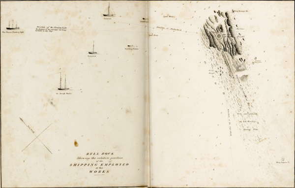
BELL ROCK Shewing the relative position of the SHIPPING EMPLOYED at the WORKS
Drawn by J. Steedman
Engd. by W. H. Lizars
PLATE V.
Pl. V.
This Plate represents the Rock at low-water of spring-tides, when that part of it which extends about 1000 feet in a south-western direction from the Light-house, may be traced by the appearance of some detached portions of rock, but chiefly from the sea-weeds which float at the surface of the water. Its greatest extent, in a north-eastern and south-western direction, is about 1400 feet, and in a south-eastern and a north-western direction about 240 feet.
King George III.—This is an insulated rock which lies towards the south-eastern extremity of the Main or House Rock, and has been named in reference to the reign in which the Light-house was erected.
King James V.—is also a detached rock, forming the south-western extremity of the reef, which extends from the House-rock, and is named in reference to that Monarch’s memorable voyage round his dominions, about the year 1540, as alluded to in the Introduction, at page 4.
On the north-western side of the Rock, as nearly as may be, the figures of the respective vessels employed at the work are delineated, and the positions of their moorings laid down; with the exception of those of the Pharos Floating-light, whose bearing or direction is only to be understood, as the full distance at which she was ultimately moored would fall beyond the limits of the Plate. The house-part of the Rock is left bare at low-water of ordinary spring-tides, and at high-water of these tides it is from 10 to 12 feet under water; but during the storms of winter, the sea generally breaks over the whole surface of the rock, so as to render walking upon it impracticable, even in the lowest ebbs; while at high water, the sprays fly over the building, or rise to a height of upwards of 100 feet. The reef, which extends in a south-western direction from the House-rock, contains many Travellers or large boulder-stones; affording a proof that the Bell Rock has at one time been of greater dimensions than at present, and these detached stones may be regarded as part of the debris, which have been separated in the lapse of ages from the main Rock.
Plate VI. PLAN OF THE NORTH EASTERN PARTS OF THE BELL ROCK, SHEWING THE POSITION OF THE LIGHT-HOUSE, RAILWAYS, AND WHARFS, &c.
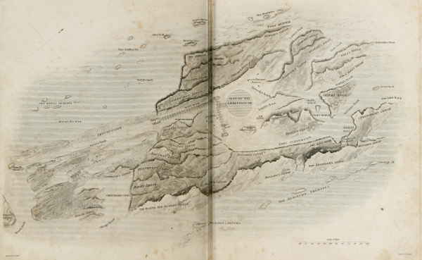
NORTH EASTERN parts of the BELL ROCK shewing the position of the LIGHT HOUSE, railways, wharfs, &c.
Drawn by G. C. Scott
Engd. by E. Mitchell
PLATE VI.
Pl. VI.
The description of this Plate, representing the higher parts of the Rock as seen at low-water of spring-tides, affords the writer an opportunity of mentioning many distinguished names connected either officially, or in a friendly manner, with the erection of the Light-house. In corresponding about the state of the Rock, he has often found the advantage of this particular nomenclature of its different parts, as affording a reference to all its localities.
Site of the Light-House, and Railway-Tracks.—The site of the Light-house, which will be seen from the Plate, was fixed by the writer in a central position of what may be termed the House-Rock. From this, as a centre, the Railways ramify in various directions. Upon these the materials for the erection of the house were conveyed, and they are still partly preserved, as convenient foot-paths and wharfs, in landing stores for the Light-house. The portions of the Railway-tracks marked with light dotted lines, were only used during the continuation of the works; while those of a deeper shade represent the permanent railways.
Site of Captain Brodie’s Beacon.—The late Captain Joseph Brodie, of the Royal Navy, was perhaps not less known to the public as the fortunate bearer of Lord Duncan’s dispatches announcing the victory obtained by the British fleet off Camperdown, than for his unwearied exertions in keeping up the interest of the public, relative to the important results to navigation which would attend the erection of a Light-house upon the Bell Rock, of which notice is taken at page 88.
Site of Mr Stevenson’s Beacon.—The position of the Beacon or temporary erection delineated in Plate VIII., was fixed upon the southern side of the site of the Light-house, with the ultimate view of obtaining shelter from the breach of the north-east seas. It was farther important, for the conveniency it afforded of a communication during the progress of the works, by means of a wooden bridge, which will be understood by examining Plate XVIII.
Haldane’s Ledge—is situate on the south-eastern side of the Rock, where the writer made his first landing with his friend Mr James Haldane, architect, as noticed at page 91.
Gray’s Rock.—Toward the eastern side of the Rock, there is a small outlier, or reef, important as a low-water-mark, which is named Gray’s Rock, in compliment to the late Mr John Gray, Writer to the Signet, and the first Secretary to the Light-house Board, as noticed in the Introduction, page 5.
Smith’s Rock,—situate on the eastern side of the Light-house, derives its name from the late Mr Thomas Smith, who introduced Reflecting-Lights upon the coast of Scotland; and was the first Engineer to the Board, as noticed at page 7.
Cuningham’s Ledge.—This ledge of rock has its name from Mr Charles Cuningham, Writer to the Signet, and successor to Mr Gray, as Secretary and Cashier to the Light-house Board.
Port Hamilton.—This creek is situate at the south-eastern extremity of the House-rock, and derives its name from Mr Robert Hamilton, Sheriff of Lanarkshire, and ex officio one of the Commissioners of the Northern Light-houses; who first landed here in the year 1805, accompanied by Mr Rennie and the writer, with a view further to ascertain the practicability of erecting the proposed Light-house, as noticed at page 95. Mr Hamilton has been a zealous member of the Bell Rock Committee since the period of its institution in the year 1807, and, from his literary habits, he has taken much interest in the pages of this work.
Port Rennie—is situate in the north-eastern part of the House-rock, and derives its name from the late Mr John Rennie, the celebrity and extent of whose works as a Civil Engineer are well known to the public. Mr Rennie was consulted by the Light-house Board relative to this work. His reports will be found in Appendix, No. IV.; and his plan in Plate VII.
Port Stevenson—enters from the north-eastern side of the Rock, and forms the principal landing-place in that direction; it was named for the writer by Mr Hamilton, at the landing above alluded to, in the year 1805.
The Abbot’s Ledge—forms the north-western extremity of the House-rock, and derives its name from a tradition (for we can find no authentic record) of one of the Abbots of Aberbrothwick having erected an Alarm-bell, to forewarn mariners of their danger in approaching the Bell Rock.
Sir Ralph the Rover’s Ledge—forms the south-western extremity of the House-rock, and takes the name of Sir Ralph the Rover from a noted pirate who is said to have landed upon it, and carried away the Alarm-bell. This traditionary story is beautifully alluded to in a ballad by Mr Southey in his Minor Poems, which, with his permission, is included in Appendix, No. II. page 438.
Dunnichen Ledge,—on the north-western side of the Rock, is named in compliment to Mr Dempster of Dunnichen, who is mentioned in the Introduction, page 5.
Dunskey Ledge,—which is contiguous to the former, is named in compliment to Sir James Hunter Blair of Dunskey, first Preses of the Commissioners of the Northern Light-houses, as mentioned at page 6.
Arniston Ledge.—Named in compliment to the late Lord Chief-Baron Dundas of Arniston, who, while Solicitor-General and Lord Advocate of Scotland, took an active part in Light-house affairs; and visited the Bell Rock in the year 1812, as noticed at page 413.
Rattray Ledge.—In compliment to Mr Baron Clerk Rattray, who, while Sheriff of the Shire of Edinburgh, as noticed at page 98, was ex officio one of the Commissioners of the Northern Light-houses, and, as one of the Bell Rock Committee, took much interest in the work.
Hope’s Wharf—forms the termination of the permanent railway toward the west. It was named for the Right Honourable Charles Hope, Lord President of the Court of Session, who landed here in the year 1815. While Lord Advocate of Scotland, he took a warm interest in the affairs of the Northern Light-houses, and in 1803 brought the first bill into Parliament for the erection of the Bell Rock Light-house, as noticed at page 93.
Pulteney Ledge.—So named in compliment to Sir William Pulteney, who, as a Member of Parliament, took a lively interest in the bill brought forward for the Bell Rock Light-house in the year 1803, as alluded to at page 92.
Banks Ledge.—Named in compliment to Sir Joseph Banks, who was Vice-President of the Board of Trade in the year 1806, when the Bill for the Light-house was in Parliament, and who took much interest in it, as noticed at page 101.
Cochrane’s Ledge—is named in compliment to Admiral Sir Alexander Cochrane, who first called the attention of the Light-house Board to an erection upon the Bell Rock, as mentioned at page 85.
Port Erskine—forms the principal landing-place on the western side of the Rock, and derives its name from the Honourable Henry Erskine, who, when Lord Advocate of Scotland, and ex officio one of the Commissioners of the Northern Light-houses, brought the second Bill for the Bell Rock Light-house into Parliament, which passed in the year 1806, as stated at page 100.
Ulbster Ledge.—Named in compliment to the Right Honourable Sir John Sinclair, Baronet, of Ulbster, Chairman of the Committee of the House of Commons, and who brought up its report relative to the Bell Rock bill, as stated at page 103.
Kellie Ledge.—Named in compliment to the Earl of Kellie, who visited the works at the Bell Rock in the year 1810, as noticed at page 378.
Pitmilly Wharf—formed the western extremity of the landing-wharf in use during the Light-house operations, and was named in compliment to Mr Monypenny, now Lord Pitmilly, who, while in the commission both as Sheriff of Fife and Solicitor-General of Scotland, was a member of the Bell Rock Committee, and visited the works in the year 1810, as stated at page 378.
Kinedder Ledge—is named in compliment to the late Mr William Erskine, Sheriff of Orkney and Shetland, and a member of the Bell Rock Committee. From Mr Erskine’s literary pursuits, he took a lively interest in this work, before he left the Light-house Board, and also after he was raised to the Bench, where he took his seat as Lord Kinedder.
The Abbotsford.—This spot, where the waters of the two principal and opposite landing-places meet, is named in compliment to Sir Walter Scott, Baronet, of Abbotsford, who landed here in the year 1814, as noticed at page 419, when he wrote the beautiful and expressive lines inserted in a fac-simile of his handwriting in the 2d Title-page.
Rae’s Wharf—forms the extremity of the southern reach of the permanent railway, and derives its name from Sir William Rae, Baronet, who, in the several capacities of Sheriff-Depute and Lord Advocate of Scotland, has long been a member of the Light-house Board and Bell Rock Committee. His Lordship visited the Rock in 1810, as noticed at page 387.
Duff’s Wharf—derives its name from Mr Adam Duff, Sheriff of the shire of Edinburgh, and a member of the Bell Rock Committee, who repeatedly visited the works at the Bell Rock while in progress, particularly in the year 1810, as noticed at page 387.
Port Boyle—takes its name from the Right Honourable David Boyle, Lord Justice-Clerk, who, while Solicitor-General of Scotland, was a member of the Bell Rock Committee, and visited the Light-house in the year 1811, as noticed at page 411.
The Crown Lawyers.—This name is given to two detached rocks, which lie on the south-eastern side of the House-rock, in allusion to the Lord Advocate and Solicitor-General of Scotland, who are ex officio Commissioners of the Northern Light-houses, as noticed at page 6.
The Maritime Sheriffs.—This name comprehends a range of rocks, also on the south-eastern side of the main Rock, in reference to the Sheriffs of maritime counties, who are ex officio Commissioners of the Northern Light-houses, as noticed at page 6.
The Royal Burghs,—A group of rocks lying on the south-western side of the House-rock, so named from certain of the Chief Magistrates of the Royal Burghs of Scotland who are ex officio Commissioners of the Northern Light-houses, as noticed at page 6.
Telford’s Ledge—is named in compliment to Mr Thomas Telford, Civil Engineer, who was requested by Sir William Pulteney to visit the Bell Rock professionally in the year 1803, as noticed at page 92.
Downie’s Ledge—derives its name from the late Mr Murdoch Downie, a Marine Surveyor of considerable eminence, who suggested a plan for erecting a Light-house on the Bell Rock, as noticed at page 93.
Neill’s Pool—derives its name from Mr Patrick Neill, a particular friend of the writer’s, who first visited the Bell Rock in 1808, as noticed at page 235. The surface of this pool measures about three fathoms across, and a fathom and a half in depth, when the tide leaves the Rock. The bottom is generally covered with boulder-stones, which are whirled about with much force when the sea is in a state of agitation.
Stuart’s Track—is on the south-western side of the Rock, derives its name from the late Captain Harry Stuart of the Royal Navy, who visited the Bell Rock in the year 1810, as alluded to at page 387. Captain Stuart took an early interest in the plans for the Light-house, both by Captain Brodie and the writer.
Bruce’s Ledge—was named in compliment to the memory of the late Mr James Bruce of the Naval Yard, Leith, who frequently visited the Bell Rock, and to whose ingenuity the Light-house service is indebted for the improved construction of a boat, delineated in Plate XI. and noticed at page 412.
Russell’s Ledge—is named in compliment to Mr Claud Russell, Accountant to the Light-house Board, who visited the Rock in the year 1812, as mentioned in page 414.
Scoresby’s Point,—the most northern part of the Rock, named in compliment to the writer’s friend Captain Scoresby junior, who has so much extended our information regarding the Polar Regions.
Trinity Rock.—This rock is named in compliment to a Committee of the Trinity House of Leith, consisting of Messrs Thomas Grindlay, John Hay, and Thomas Ritchie, who gave their advice and assistance in the fitting out and mooring the Floating-light in the year 1807, as alluded to at page 110.
Balfour’s Ledge—is named in compliment to the late Provost Balfour of Arbroath, who felt the most lively interest in the Light-house affairs. In his hospitable mansion the writer occasionally resided while the works were in progress.
Leitch’s Ledge—is named in compliment to the writer’s friend Mr Quintin Leitch, who visited the Rock in the year 1818. Mr Leitch is further noticed at page 43.
Pillans’s Ledge—is named in compliment to the writer’s friend Mr James Pillans of Leith, who took an early interest in the erection of the Light-house, and who signs the Report of the Merchants of Leith regarding it, as noticed at page 96.
The Last Hope.—This name was given by the writer to the highest part of the rock, in allusion to the narrow escape which he and the artificers made in the year 1807, by the timeous arrival of James Spink, the Bell Rock pilot at Arbroath, as noticed at page 149. Spink is a remarkably strong man, whose tout ensemble is highly characteristic of a North-country fisherman. He usually dresses in a pé-jacket, cut after a particular fashion, and wears a large flat blue bonnet. A striking likeness of Spink, in his pilot-dress, with the badge or insignia on his left arm, which is characteristic of the boatmen in the service of the Northern Lights has been taken by Howe, and is in the writer’s possession.
Forrest’s Passage.—This gully or opening on the eastern side of the Rock, is sometimes taken as a track by boats in certain states of the sea and tide. It derives its name from the late Mr John Forrest, Superintendant of Lightkeepers’ duty in the service of the Northern Lights, who is particularly noticed at page 406.
Logans’ Reach.—This reach or compartment of the Railway, on the eastern side of the Light-house, is named in compliment to the late Mr Peter Logan, foreman-builder at the Bell Rock, and his son Mr David Logan, clerk-of-works, whose active and faithful services, in their respective departments, have been too often noticed in this work to admit of reference to particular pages.
Watt’s Reach—has its name in compliment to Mr Francis Watt, foreman-mill-wright, whose services have also already been often particularised in the course of this work, and whose exertions in erecting the beacon and temporary-railways did much credit to his zeal and intrepidity. The writer also often profited by his ingenuity, in reference to the various pieces of machinery employed at the works.
Kennedy’s Reach—derives its name from Mr Lachlan Kennedy, who, as Accountant and Cashier in the Engineer’s Office, discharged the various duties of his situation in a manner equally creditable to himself and satisfactory to his employers. An Abstract-Account of the expence of the work, as drawn up by him, appears in the Appendix, No. VII. page 475.
Slights’ Reach,—named in compliment to Mr James Slight, and his brother Alexander, who were chiefly employed in drawing the courses of the building at large, and in making the various and nicely formed moulds for fashioning the stones. They also fitted up the interior of the house, and the permanent railways on the rock; and made a complete model of the Light-house.
The Smiths’ Forge and Ledge—named in compliment to Mr James Dove, foreman-smith, and his assistants, who have been frequently alluded to in these pages. It was here that the forge was erected at the commencement of the works on the Rock; and on the connecting ledge the first or experimental cargo of stones was landed.
Reid’s Ledge—is named in compliment to Mr John Reid, the first principal Lightkeeper at the Bell Rock, who retired from the service in the year 1821, as noticed at page 422.
Selkirks’ Ledge,—named for Mr Robert Selkirk, principal builder, and his brother Thomas, who was the principal stone-cutter at the work.
Wishart’s Ledge—is named for Mr Michael Wishart, some time principal builder at the Rock, as noticed at page 291.
Glen’s Ledge.—This ledge has its name from Mr James Glen, millwright and joiner, particularly noticed at page 279.
John Watt.—A detached rock on the western side of the main rock, named for John Watt, principal mortar-maker at the Bell Rock.
Peter Fortune.—A detached reef on the western side of the Rock, named for a well known character in the Light-house service, as noticed at page 299.
Gloag’s Track—leads into Port Hamilton, and is named for Mr Robert Gloag, who commanded the Light-house Yacht in the year 1807, and who has otherwise had a good deal of connection with the Light-house service.
Macurich’s Track—on the western side of the Rock, is named in compliment to Mr Thomas Macurich, mate of the sloop Smeaton, and afterwards commander of the Bell Rock Tender, who had a very narrow escape in a boat off the Rock, as noticed at page 253.
Webb’s Rock—is named in compliment to Mr Joseph Webb, one of the King’s pilots at Yarmouth, who superintended the fitting out and mooring of the Floating-light, as noticed at page 108.
Sinclair’s Track—is named in compliment to Mr George Sinclair, who, in 1807, commanded the Floating-light, and acted as landing-master.
Wilson’s Track—named for Mr James Wilson, landing-master, whose active and enterprising conduct is often noticed in the course of this work. In the year 1815, Mr Wilson left the Light-house service, when he was appointed one of the Harbour-masters of Leith. The speaking-trumpet which he used at the Bell Rock was presented to him, with the sanction of the Light-house Board, when a suitable inscription was engraved on a plate of silver attached to it.
Taylor’s Track—leads into Port Erskine, and derives its name from Mr David Taylor, who commanded the Sir Joseph Banks Tender during the progress of the works, and afterwards became Light-house Storekeeper at Leith.
Calder’s Track—situate on the north-western side of the Rock, derives its name from Mr Thomas Calder, who commanded the Light-house Yacht, and other craft, connected with the works, as noticed at page 260.
Soutar’s Track—derives its name from Mr Peter Soutar, who was one of the Praam-masters while the works were in progress. In 1815 he succeeded Mr James Wilson in the command of the Light-house Yacht.
Pool’s Track—is named for Mr Robert Pool, commander of the Smeaton stone-lighter, a very active and persevering seaman.
The Engineers’ Ledge,—situate on the eastern side of the Rock, is named in compliment to certain of the Engineer’s assistants, who, though belonging more especially to his general or private business, have nevertheless been occasionally employed in the department of the Bell Rock, particularly Mr John Steedman, Mr John Thin, Mr William Lorimer, Mr G. C. Scott, and Mr Robert Shortreed, some of whose names are attached to several of the Plates.
The Artificers.—A name given to a parcel of detached rocks, lying on the north-western side of the main Rock, in allusion to the numerous artificers employed at the works, many of whom are now moving in spheres of more extended usefulness, and, did our limits admit, would be deserving of particular notice, as may be learned from page 379.
The Mariners.—This is also a group of detached rocks on the north-eastern side of the Rock, which in like manner is named in compliment to the exertions of the Seamen, who, as men-of-all-works, gave a helping hand to every operation; and many of whom deserve the warmest acknowledgments of the writer.
Strachan’s Ledge,—situate on the north-eastern side of the Rock, was named for Mr Robert Strachan of Leith, who fitted out the Floating-light, and narrowly escaped being lost upon the Rock, when approaching it in a boat which was upset in the year 1808, as noticed at page 244.
Craw’s Horse.—Another detached rock, deriving its name from a narrow escape which the sloop Smeaton made in foggy weather, as noticed at page 364, while James Craw, who had charge of the stable, and was principal carter at the work-yard of Arbroath, was on board, with his favourite horse, on his way to Leith, to convey the upper part of the Light-house, from Edinburgh, to be shipped for the Bell Rock. The horse alluded to was a remarkably strong and powerful animal, measuring about 16 hands in height, and having, in the language of jockies, a great deal of bone. It is not a little remarkable, that while the work was in progress, this animal must actually have drawn the materials of the Light-house, extending to upwards of 2000 tons in its finished state, perhaps three or four times, in removing the blocks of stone from the ship to the work-yard, again to the platform, and from the work-yard, when they were to be shipped for the Rock, besides occasional movements to and from the hands of the stone-cutters. A sketch of this animal, and of his master James Craw, will be found at Fig. 21. Plate X. The horse having failed from age, towards the close of the work he was removed to the Island of Inchkeith, to go at large, where he died in the year 1813. The fame of this animal’s labours, together with his strength and excellent proportion as a draught-horse, having attracted the notice of Dr John Barclay, that eminent anatomist procured the bones, and set them up in his Museum. This valuable collection, it is understood, is to be bequeathed to the College of Surgeons of Edinburgh; so that the bones of the Bell Rock-horse, to use the Doctor’s own language, “will be seen and admired as a useful skeleton, and a source of instruction, when those of his employers lie mingled with the dust.”
Plate VII. ORIGINAL DESIGNS FOR THE BELL ROCK LIGHT-HOUSE.
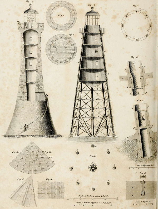
DESIGNS for the BELL ROCK LIGHT HOUSE by Mr. STEVENSON.
DESIGN for the BELL ROCK LIGHT HOUSE by Mr. RENNIE.
Drawn by J. Slight
Engraved by R. Scott
PLATE VII.
Pl. VII.
Fig. 1. shews the sites of the principal and diagonal supports of cast-iron of the Pillar-formed Light-house, modelled by the writer prior to his landing on the Rock in the year 1800, as alluded to in his report, included in the Appendix, No. IV. at page 440. This Figure is a Plan in which letters a a a a a a a a point out the feet of the eight principal columns; e the central shoe or socket, intended to receive the feet of the diagonal supports or braces, which correspond in number with those of the main columns. This fabric, at the base, was to form a common diameter of about 35 feet, diminishing to 12 feet at the top, or immediately under the Light-room.
Fig. 2. The great columns in this design, which are sunk into the Rock, and the diagonal braces d d d d, which butt against, or step into the shoe c, are also strongly connected by the braces b b b b b b b b, and cross ties marked c c c c c c. The habitable part of this building is formed by two concentric rings of copper, marked a f, a f, the one upon the outside, and the other upon the inside, of the main columns. The space between these rings was to be filled with plaster-of-Paris, or some light substance, to render the apartments air-tight. Letter g is the position of the entrance-door, and the space below the first floor, marked h, is a coal magazine. The better to throw off the sprays of the sea, the lower part, as will be seen from the diagram, is of a conical form inverted.
Fig. 3. Shews the mode of fixing the principal columns, to the Rock, and of building or connecting them together, being an enlarged section of the foot of one of the main columns. The hollow cylindrical tube marked b b, is sunk 24 inches, and acts as a steady pin or joggle to the column which is wedged into the Rock, as shewn at c c c c, by driving oaken and iron wedges alternately, instead of running them up with melted lead. The next length of the column, marked a a a a, is slipped over this tube, and has a seat cut in the rock at right angles to the oblique direction of the column, to which it is connected by the cutter or spear-bolts marked d d d, whose directions respectively cross each other, as shewn in the section.
Fig. 4. represents one of the joints of the main columns, which occur at every 7 feet of their length, from the rock to the habitable part of the Light-house. This description of joint is what is technically termed spigot and faucet; a a is the upper half, b b b the lower, c c the joint, d d d d the collar-piece clasping the joint, and connecting it with the horizontal arms or braces e e, which, in Fig. 2, are marked b, and in connection with the cross ties c, and diagonal-supports d, bind the whole firmly together.
Fig. 5. represents the lower floor of the five apartments, in which a a a a a a a a, as in the foregoing Figs. 1, 2, and 3. shew the main columns passing between the outer covering and inner lining of copper. Letter c marks the entrance door, shewn at g, in Fig. 2., in which d is the plat at the top of the ladder, formed on one of the columns, which may also be conceived as passing up through the habitable part of the building; the floors of which are formed with plates of cast-iron.
Fig. 6. represents a Light-house of masonry, modelled by the writer immediately after his first landing upon the Rock. The better to illustrate this design, the solid or lower part is given in elevation, and the upper or habitable part in section. Compared with the Edystone Light-house, upon the principles of which it was designed, the chief differences consist in the exterior spiral-formed stair, intended to afford permanent access to the Light-house, and also to serve as a landing quay or wharf at high-water. The steps of this stair were to be 3 feet in length, forming a kind of scarsement upon the outer-wall, there being nothing to obstruct the force of the sea under the stair; as it formed part of the main-wall, it may be conceived calculated to have become a kind of spiral buttress to the building. In the upper or habitable part, the interior walls diminish gradually, instead of forming abrupt scarsements, and the floors were laid horizontally, instead of being arched.
Fig. 7. Shews one of the floors, each stone of which forms part of the outward walls, extending inwards to a centre stone, independently of which they were to be connected, by means of copper-batts, with a view to preserve their square form at the extremity, instead of dove-tailing. These stones were also modelled with joggles sidewise, upon the principles of the common-floor, termed Feathering in carpentry; and also with dove-tailed joggles across the joints, where they formed part of the outward wall, as shewn in this figure.
Fig. 8. is a plan of one of the courses of the void or habitable part of this design, shewing both the joggles of the end joint and the girth, raised upon the upper beds of the courses, and sunk into the groove cut in the lower beds of the respective covering courses.
Figs. 9. and 10. exhibit different modes of connecting the stones and courses of the solid of the building, both perpendicularly and horizontally, by means of dove-tailing. But as a certain degree of weakness is unavoidably incident to every system of dove-tailing, and, as the method of forming the bed-joints of the void above alluded to is equally effective, in its application to the solid or lower part of the building, as represented in Plate XXIII., this is considered preferable to the dove-tailing system.
Fig. 11. is part of a course, shewing a simple mode of connecting the stones in water-buildings, so as to avoid dove-tailing, and preserve, as much as possible, the entire figure of the stones. This is effected by inserting square joggles into the joints, and allowing these joggles to project 6 inches into the course immediately above, thereby forming a connection horizontally between the stones of a course, and vertically with the several courses.
Fig. 12. is also a course of masonry, in which the square or entire form of the materials is preserved, while the stones are bound both horizontally and vertically, by means of metallic-batts and plates, as represented in the enlarged diagram described in the following Figure.
Fig. 13., a is the dove-tailed cross-head or plate; b is a section both of the batt and plate, in their places, shewing their connection with two courses of the building marked A B; c shews the mode in which the batt is fixed into the lower course, by means of wedges; d the upper end of the batt and plate, which is also wedged, and appears, when in its place, as in Fig. 11., marked also a a a. But these several modes of connecting the materials of masonry are considered more or less objectionable, when compared with the girths delineated in the design represented in Plate XXIII.
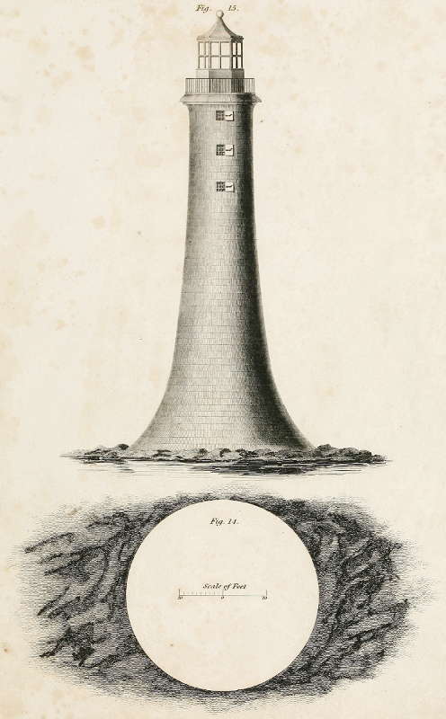
Figs. 14. and 15. are a reduced plan and elevation of the Bell Rock Light-house by Mr Rennie, in the year 1807. They will be found so obvious upon inspection, as not to require explanation, and are here preserved as the only plans or drawings furnished for this work by that eminent engineer.
Plate VIII. BEACON-HOUSE.
BELL ROCK BEACON
Drawn by W. Lorimer
Engd. by W. H. Lizars
PLATE VIII.
Pl. VIII.
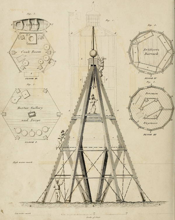
Fig. 1. represents the Beacon-house, which was used as a barrack for the artificers during the working seasons of 1809 and 1810. Letter A A A is the surface of the Rock. The principal legs or beams, with their diagonal supports, radiating from the centre of the plan, are marked a a a a a a, and the bracing chains b b b, as completed in the year 1807. In 1808 the bracing-chains were removed, and the malleable iron-bars marked c c c were substituted. The dotted lines d d d d d, are intended to show the form of the upper or habitable part of the Beacon as it was ultimately finished, with its lantern, for ventilating the barrack-room. One of the figures characterised as sailors, and used for illustrating this elevation, is represented as standing upon the Rock, and laying hold of one of the bracing-chains. The next figure is ascending the trap-ladder, formed with cleats of timber nailed upon one of the principal beams; he is on a level with the mortar-gallery, marked letter e e e. The third figure is standing upon the cross or collar-beams, nearly on a level with the floor of the cook-room, marked f f. The fourth, or highest figure, is standing upon one of the principal beams, with his feet on a level with the top of the windows in the floor of the cabins of the engineer and his assistants marked g g; the head of this figure being within the artificers’ barrack, marked h h. With one hand he is supposed to be touching the provision-chest, marked i, and with the other he is laying hold of the rope for hoisting the copper signal-ball k upon the flag-staff.
Fig. 2. represents the gallery where the mortar-makers and smiths latterly worked. a a a a a a represent the principal beams of the Beacon cut across; b b b the position of the mortar tubs and lime-casks; c the smith’s anvil; d his bellows; e the hearth or fire-place.
Fig. 3. represents the floor of the cook-room, in which a a a a a a shew the principal beams cut across; b the platt or landing at the entrance-door; c c the coboose or cooking-hearth; d the chimney or smoke funnel; e e e e the provision casks; f the trap stair leading to the floor above; g g the small life-boat, suspended by davits from the principal beams of the beacon; i i i i i i the six angular upright posts cut across, marked d in Fig. 1., which form the framing of the hexagonal apartments or floors marked III. and IV. Letter k represents the position of the privy, and stair leading to it.
Fig. 4. is the floor of the cabins of the engineer and his assistants. Letters a a a a a a mark the position of the six principal beams of the beacon, now approaching closely together from their diagonal direction: b b b b b b the angular upright posts, which, together with those marked i i i i i i, as referable to Fig. 3., form the upper apartments into twelve sides; c is the trap-ladder, corresponding with letter f in Fig. 3., which communicates with the cook-room floor below; d is another ladder, leading to the artificers’ barrack above.
Fig. 5. represents the upper floor, or that of the artificers’ barrack-room, on a level with the top of the principal beams, marked a in Figs. 1, 2, and 3. In this diagram a a a a a represent the ground-tier of beds, which were ranged in five heights, excepting at the space over the man-hole, leading up to this apartment, where there was only three heights of beds; c represents the trap ladder answerable to letter d of Fig. 4.
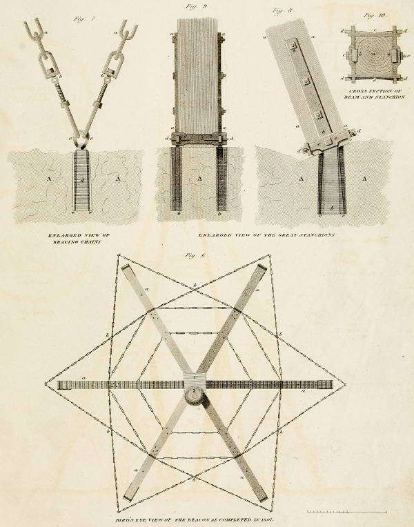
Fig. 6. represents what may be termed a bird’s-eye view of the Beacon, as completed in 1807, and before it was converted into a barrack. In reference to Fig. 1., letter a represents the six principal beams, forming a common base measuring about 35 feet across, including the bracing-chains, which are marked b b b b b b. These beams meet in a point at the top, where they rest upon a block of beechwood, to which the upper ends of the beams were fitted, the whole being girded with strong malleable iron rings or hoops, keyed with spear-bolts. Here the provision-chest i, and signal-ball k, are represented as resting upon the top of the principal beams.
Fig. 7. is an enlarged view of two of the bracing-chains, marked a a, with their tightening shakle marked b b, meeting in the ring c c. Letter d represents one of the batts, which were sunk into the rock A A about 20 inches, and wedged with timber and iron, as shewn at e e.
Fig. 8. represents a side view of one of the beams of the beacon, marked a a a a, cut across immediately above the great stancheons b b b b, with its bolts, which were fitted upon each side of the beam; c c represent the clasp-plates, which embraced each foot of the beacon, with its two stancheons. These clasp-plates were fixed with spear-bolts, as shewn at d d. Letters e e represent the wedging with timber and iron, referred to in Fig. 7.
Fig. 9. represents a front view of a like portion of one of the principal beams, as in Fig. 8.; a a a a shew the stancheons on each side of the beam, and b b the lower extremity of the stancheons sunk into the Rock A; c c one of the clasp-plates; d d d d the spear-bolts.
Fig. 10. is one of the principal beams, a cut across at the clasp-plate c c c c. Letters b b are the great iron-stancheons; and d d d shew the spear-bolts.
Plate IX. SHEWING THE PROGRESS OF THE WORKS DURING THE SECOND, THIRD, AND FOURTH YEARS’ OPERATIONS.
Progress of the Bell Rock Works.
Drawn by J. Slight.
Engd. by W. Miller.
PLATE IX.
Pl. IX.
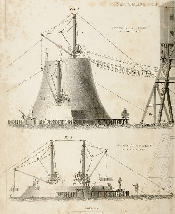
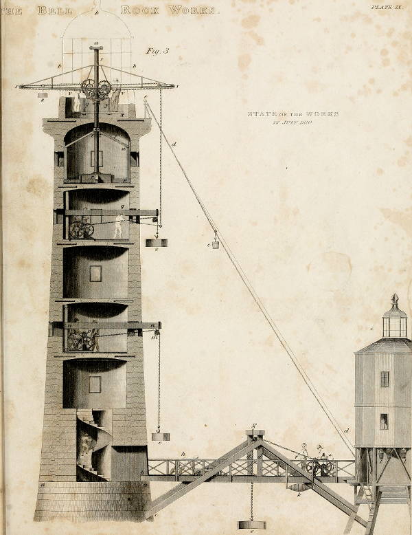
Fig. 1. shews the state of the works about the close of the second season, or year 1808, with two of the moveable beam-cranes, with their guy tackles and working gear, which will be more particularly described under Plate XIV. These are placed upon the top or fourth course of the building. In the fore-ground, part of the unfinished railways are seen, with waggons and artificers at work; and on the right the beacon is partly traced in faint lines.
Fig. 2. represents the state of the works in the month of August 1809, at the close of the third season’s work, when only one of the cranes was set upon the building; the other, as the work increased in height, and became less in diameter, was placed upon a temporary stool or prop of masonry, marked a a a a. This prop was found extremely useful, as, by elevating one of the cranes upon the top of it, the lift of the materials was divided, and brought more conveniently within reach of the higher crane, which at this period was about 30 feet above the Rock. In the fore-ground of this diagram, part of the circular track of railway round the building is seen. On the right, a part of the Beacon-house appears with the rope-ladder of communication, extending from the top of the solid of the Light-house to the mortar-gallery. On the rope-ladder a figure is represented walking from the Beacon to the Light-house, and a tackle, with its travelling pulley, is also stretched, for conveying the mortar-bucket, to the builders.
Fig. 3. represents a section of the void or habitable part of the Light-house as it appeared in the month of August 1810, when the masonry was nearly completed. On the right is an elevation of part of the Beacon-house, but instead of the rope-ladder of communication, a bridge of timber is constructed. Letters a a represent the top of the solid, or level of the entrance-door of the building, from which the stair-case ascends to the several apartments. Resting on the sill of the door at b, is seen one of the beams for supporting the road-way of the bridge, and below this, at the point c, is the step of one of the diagonal braces of the bridge, where it is inserted about 6 inches into one of the courses of the solid masonry. Regarding the frame-work of the bridge, it may only further be noticed, that the road-way was chiefly suspended from the king-posts d d.
Letter e represents a block of stone, in the act of being raised from the rail-way on the Rock, to the level of the bridge, by means of the crab or winch-machine marked f, with wheel and pinion apparatus; the pully of the working chain is suspended from the cross beam g, which rests or is supported upon the top of the king-posts. One of the figures on the bridge at h, is in the act of pushing forward a truck cart or waggon i, to receive the stone e; when raised through the aperture in the road-way, it is then lowered upon this waggon, and removed towards the building within the sphere of the several purchases or machines, by which it is transported to the hands of the builders.
Letter k refers to a life-buoy, and a coil of rope, kept in readiness upon the bridge, in case of accident by the fall of any of the people from the building or beacon while the Rock was covered by the tide. l l represent two of the fire-buckets, which were hung round the beacon, under the projection immediately above the cook-room. The stone marked e, in the second stage of its progress towards the top of the building, is now seen immediately above the lintel of the entrance-door, the purchase chain, by which it is suspended, passes over a pulley at m, attached to the beam n n, which is projected from one of the windows of the Light-room store, where it is supported upon a block of timber, so as to admit of the chain passing under it. The further end of this beam, being within the Light-house, was bolted to an upright post marked o o, and the whole apparatus was worked by means of the crab or winch-machine at p, similar to that upon the bridge marked f f. The stone e is next supposed to have gained the height of the floor of the bed-room, where another apparatus, similar to those at f and p, is placed. Here a figure is represented at q, with a rod in his hand, in the act of hooking the chain of the balance-crane into the Lewis-batt, fixed in the stone e, still in its progress to the top of the building. r r r represent the strong oaken beams placed on the floor of the library, on which the foot of the cast-iron balance-crane is supported. s s two of the four diagonal braces of oak timber, bolted into a collar-piece of cast-iron, clasping the upright shaft of the crane at t t, and butting against the upright stretchers at u u; intended as a security to the walls, in case the balance-crane should at any time get out of equilibrium. The two figures marked v v, are represented as working the balance-crane, and are supposed to be standing upon a moveable platform x x, suspended from the body of the crane by rods of iron y y. This platform or stage, with the artificers upon it, being moveable with the body of the crane, gave great facility and conveniency to those who wrought it. z is the balance-weight, moveable by the machinery along the balance-beam of the crane, to keep the whole in a state of equilibrium, according to the varied load suspended from the working or opposite beam; accented á represents the moveable block or cross-head of malleable iron, with two eyes, into which the chains of the crane were hooked, when the body (comprehending the machinery and beams) was to be elevated upon the shaft in the progress of building. But the cross-head, together with the other apparatus of this machine, will be better understood by examining Plate XVII., with its letter-press description. b´ b´ b´ represent the form and position of the Light-room in dotted lines; c´ the mortar-bucket made to traverse upon the guide-rope d´ d´, stretched between the building and the mortar-gallery of the Beacon; the end of the rope attached to the building being fixed to the stanchion é, inserted into one of the Lewis batt-holes, on the balcony of the Light-room.
Plate X. VARIOUS IMPLEMENTS AND APPARATUS CONNECTED WITH THE WORKS.
CERTAIN IMPLEMENTS connected with the BELL ROCK WORKS
Drawn by G. C. Scott
Engd. by E. Mitchell
PLATE X.
Pl. X.
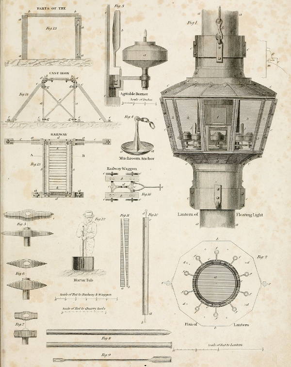
Fig. 1.—is an elevation of one of the three large copper Lanterns carried by the Pharos Floating-Light, which was moored off the Bell Rock while the Light-house was erecting. In order to relieve this vessel of the cumbrous yards with which Floating-lights were in use to be fitted, these lanterns were so constructed as to clasp round the masts, and traverse upon them. This was effected by constructing them with a tube of copper in the centre, capable of receiving the mast, and through which it passed. The lanterns were first completely formed, and fitted with brass flanges; they were then cut longitudinally asunder, which conveniently admitted of their being screwed together on the masts, after the vessel was fully equipped and moored in her station. Letters a a a a shew part of one of the masts, b one of the tackle-hooks for raising and lowering the lanterns at pleasure, c c c c c c c c c c the brass flanges, with their screw-bolts, by which the body or case of the lantern was ultimately put together; d d d shew the position of certain holes in the bottom for the admission of air, f f f f the holes at the top, connected with the ventilation, to which the collar-pieces e e and g g form guards against the immediate effects of the weather. The detached diagram, upon an enlarged scale, shows the air-hole, which is marked m. The letters h h h h shew the part of the lantern which was glazed with plate-glass; i is one of the glass shutters, by which the lamps were trimmed; the lower half being raised, slides into a groove made for its reception; k k shew the range of ten agitable burners or lamps, out of which the oil cannot be spilt by the rolling motion of the ship. Each lamp having a silvered-copper speculum or reflector l l placed behind the flame, was found greatly to increase the brilliancy of the light.
Fig. 2.—is a cross section of the bottom of the lantern, shewing the mast a cut across, b b is the sole or bottom of the lantern, c c the flanges at the junction of the body, in reference to the same letter in Fig. 1.; d d d d the small holes for the admission of air, e e e the brass zone or chandelier, with its ten arms and sockets marked f f, &c. in which the stalks of the burners are inserted. The chandelier is made to traverse horizontally into a corresponding groove fixed upon the interior cylinder or case, through which the mast passes, and upon which the whole moves up and down. When, therefore, the lamps require to be trimmed or taken out of the lantern, the chandelier is turned until they are respectively brought opposite to the shutter marked i.
Fig. 3. is an enlarged view of one of the agitable burners a, with its reflector b, which last measures four inches over the lips, and is raised to the parabolic curve of three inches focus; c the socket, d the section of the moveable chandelier in its groove, answerable to letters k and l, Fig. 1., and f and e Fig. 2. In reference to Fig. 3., e e is a section of part of the central cylinder of the lantern and mast of the ship.
Fig. 4. represents one of the Mushroom-Anchors, constructed wholly of cast-iron, used for mooring the Floating-Light and other craft off the Bell Rock, to which part of the mooring-chain is attached. This diagram seems so obvious as to require no particular description. Towards the head a a the shank is strengthened by means of four feathers or brackets raised upon it, somewhat resembling the connecting gills of the vegetable mushroom. These anchors weighed from 14 to 21 cwt.
Figs. 5. to 9.—Quarry Tools.—Fig. 5. is a common stone-pick, weighing from 8 to 10 lb., shown with and without the handle, which measured about 2 feet in length, but is here shortened. Fig. 6. is the Aberdeen or granite pick, weighing from 6 to 16 lb. Fig. 7. is a quarry hammer, weighing from 6 to 8 lb. used for jumping or boring batt-holes in the Rock, and the trenail-holes in the courses of the building. Fig. 8. represents the boring-irons for the trenail-holes, measuring 1¾ inches in breadth at the cutting end, and varying in length according to the depth of the respective holes. Fig. 9. is the scraper used for cleaning the holes; the perforated end being applied with a piece of rag for drying up the moisture.
Fig. 10. represents one of the oaken trenails used for keeping the stones in their places while the building was within the ordinary range of the sea. The positions of these trenails may be traced in the small circular holes of the courses, in Plate XIII. Their lower ends were cut with a saw-draught as at letter a, into which a small wedge marked b was inserted, and the trenail having been driven home, the small wedge had the effect of tightening or fixing it. The upper end c was then cut off flush with the upper bed of the stone, when it was split, and another small wedge, marked d, driven into the chisel-mark, which completed the operation of fixing the trenails into their places.
Fig. 11. represents a pair of the oaken wedges inserted into corresponding grooves cut into the perpendicular joints of the stones in each course of the solid or lower part of the Light-house, as may be traced in the small oblong holes, marked in the joints of the courses in Plate XIII. These wedges were chiefly intended for bringing the dove-tailed parts of the stones to a general bearing. The thick end of the wedge marked a being dropped into its groove, the smaller end of the corresponding wedge b was then inserted, and driven home till some degree of tension or firmness was obtained. This operation of trenailing and wedging was followed from Mr Smeaton’s practice at the Edystone Light-house.
Fig. 12. is a section of one of the cast-iron mortar-tubs, with its pestle, shod or loaded with a piece of malleable iron.
Figs. 13. to 15.—Cast-Iron Plate-railway.—Fig. 13. is a longitudinal view of one length of the cast-iron railways erected upon the Rock; a a a a represent the stools or upright supports, b b are the tracks of the roadway, c c one of the side stays or braces. Fig. 14. is a cross section on the line A B of Fig. 15, in which a a is the support with its cross-brace f, bolted at g g g g; b b are the railway tracks, c c c c the stays, with their connecting bolts on each side, d d the sleeper or horizontal brace connecting the top of the stools, and forming a chair or seat for the rails and grated roadway; e e e e represent the batts and spear-bolts, with which the whole was connected to the Rock, by the process of wedging with timber and iron. Fig. 15. is a plan of the finished railway; a a a a are the feet of the stools, b b the side rails or waggon-tracks, c c the stays or side braces, d d the sleepers, and h h the grated footpath. The weight of a yard in length of the railways complete, of the height of four feet, as represented in these diagrams, may be estimated about 5 cwt.
Fig. 16. represents a plan of one of the railway waggons; a is the iron handle made to hook upon either end of the waggon, so as to prevent the necessity of turning it; b b is the body of the waggon, consisting of two pieces of oak timber, bolted upon the upper part of the double frame intended for accommodating the wheels to the circular track of the railway round the building. The upper and under frames are connected with the bolt c c, so as to admit of the movement above alluded to. For the same reason, a joint was formed in the perch or middle of the frame at d. The trucks or wheels e e e e were of cast-iron, measuring 15 inches in diameter. These waggons were always left upon the Rock, being simply turned upside down, or off their wheels, in a particular part, and were seldom moved by the sea, as they weighed about 2 cwt. each.
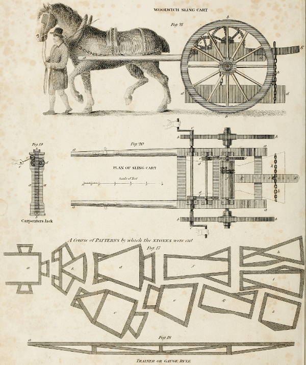
Fig. 17. The ten diagrams, marked a, b, c, d, e, f, g, h, i, and k, are a set of moulds for one course of the solid part of the building, by which the stones were cut and prepared in the work-yard previous to their being shipped for the Rock. The application and connection of these diagrams will be better understood by examining the courses of the building in Plate XIII.
Fig. 18. a Trainer or Rule, framed of timber, applied by the builders, for ascertaining the exact position of the stones of the respective courses. a is the eye or socket on which it was fitted to a steady-pin placed exactly in the centre. This rule was used chiefly for ascertaining the radiating direction of the stones, from the centre towards the circumference, being laid agreeably to corresponding notches and lines marked upon their upper-beds, so as to preserve band throughout the work, and prevent difficulty with the closing or finishing stones.
Fig. 19. is a perpendicular section of the carpenter’s jack, used with much advantage for shifting and turning the stones in the work-yard. The case of this machine was made of elm, and strongly bound at the ends with iron. It measured 4 feet in height, its greatest breadth 12 inches, and its thickness 6 inches. a a is the stock or case, b b the rack, fashioned at the lower end somewhat like the claws of a carpenter’s hammer. The upper end is of a forked form, both ends being conveniently applicable to the varied positions of the stones; c and d are the wheel and pinion work; e the handle by which the machinery is worked, affording a purchase or mechanical advantage in the ratio of about 64 to 1.
Fig. 20. is a plan of the useful machine called The Woolwich Sling-Cart, applicable to transporting large blocks of stone suspended between the wheels by means of a Lewis-batt. When a stone was of considerable length, it became necessary to employ a chain to steady it at the farther end, the application of which will be seen in this and the following figure. a a a a represent the shafts and body of the cart, b b b b the wheels, c c the handles passing between the spokes of the wheels, by which the machinery is worked for lifting the stone. The dotted line d d d d represents a plan of a stone in its state of suspension, e e e the wheel and pinion work, f the barrel or cylinder on which the chain turns as the stone is raised; g g is the tail-beam with its chain h h, and steady-pin i.
Fig. 21. represents the sling-cart in its working state, with letters corresponding to Fig. 20. Here the Bell Rock carter, and his horse, are shown, already noticed in the description of Plate VI., page 498.
Plate XI. THE SHEER-CRANE, LEWIS-BATT, PRAAM-BOAT WITH CARGO, SLOOP SMEATON DISCHARGING, AND BRUCE’s TWO-HALF ATTENDING-BOAT.
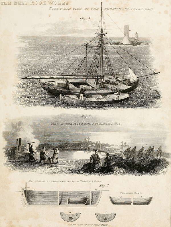
Apparatus connected with the Bell Rock Works.
Drawn by G. C. Scott
Engd. by W. Miller.
PLATE XI.
Pl. XI.
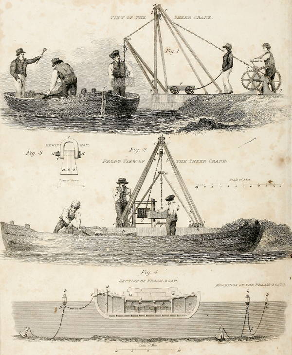
Fig. 1.—The Sheer-Crane at Duff’s Wharf. a a a are the working-sheers, to the upper extremity of which the purchase-chain a, e, g, is attached; from the hook marked i, the stone k is suspended by the sling-chain i, k, which was lengthened or shortened according to the state of the tide. b b are the upright-sheers; c c the diagonal or supporting sheers. Those last, though acting as braces, had also a motion upon the connecting block d at the top, from which the pulley e is suspended, and over which the purchase-chain passes. This motion had the effect of giving the stone a kant inwards, when the working-sheers came to the perpendicular, so as to lay it upon the waggon f, to be wheeled along the railways, as will be understood by examining Plate XVIII. The crab or winch machine g g, fixed upon the Rock at one side of the railway, with batts and spear-bolts, was worked with a less or greater purchase, according to the weight of the stone to be lifted. The large wheel measuring 3 feet 3 inches in diameter, formed the single purchase, and the smaller wheel of 2 feet 6 inches, with its pinion of 6 inches, when connected with the former by an intermediate pinion, formed the greater purchase, exerting a power in the one case in the ratio of about 20 to 1, and in the other of 98 to 1.
Fig. 2. is a front view of the machine described above, with corresponding letters. At letters h h, will be seen more distinctly the cast-iron bed, with the snugs or flanges for the reception of the lower ends of the sheers a a a and b b b b, with their journal-bolts. This apparatus, along with the other parts of the works, have been modelled for preservation.
Fig. 3. represents one of the malleable iron Lewis-batts, with which the stones were lifted from stage to stage, after leaving the hands of the stone-cutter. This useful implement consists of six members, viz. the palm, which is in three pieces, marked a, b, c; the palm-bolt d d; the shackle e. The spear-bolt f, for preventing the palm-bolt from drawing, was seldom used in practice.
Fig. 4. is a section of one of the praam-boats, shewing her cargo on deck, and more particularly the form and application of the mushroom-anchor and chain-moorings of the Bell Rock craft. a a is the cargo upon deck; b b is the hold or compartment under deck, calculated to contain a sufficient number of empty casks, for floating her, in the event of receiving injury at the rock. c c mark the fore and after peaks, for containing warps, kedge-anchors, grapplings, defenders, and other tackle; d marks the position of the bits and cross-tree to which a hook at e was fixed, for attaching the end of the mooring-chain; f is the slit in the stem, answerable to a hawse-hole, through which the mooring-chain passed almost on a level with the deep water-line, and was ultimately fixed by the ring g, to the lower swivel of the floating buoy h, and also with the mushroom-anchor i at the bottom, connected with a length of chain extending to about twice the depth of the water.
The detached diagram towards the stern of the praam-boat, consisting of a mushroom-anchor, a larger and smaller floating buoy, with their respective chains, represent the state of the moorings while the praam-boats were employed at the Rock. The small buoy k, with its chain l, was connected at the ring accented l´ to the hawser-chain of the praam. When she was unmoored, this small buoy prevented the end of the chain from sinking. In this manner the praams were conveniently disengaged, or attached to the large buoy h. When at their moorings, the small buoy k was unhooked and stowed below, the strong mooring-chain being now drawn through the hawse, or slit at f, and the ring at l´ being simply laid into the hook at e.
Fig. 5. is a perspective view of the sloop Smeaton at her moorings, delivering a cargo of stones, with one of the praam-boats along-side. In the back ground, the Light-house is seen partly built, together with the Beacon-house. Two of the three figures shewn on the deck, near the mast, are working the winch-machine of the ship in raising a stone from the hold, while the figure, in a lying posture, is holding-on the end of the tackle-fall, as described at page 144. A stone is seen in the main hatch of the ship, suspended from the end of a short boom nearly at right angles to the mast. The figure near the companion or cabin-stair is working one of the guy-tackles. On the praam’s deck, part of a cargo may be seen, and the figure towards her stern is laying hold of the stone, suspended in the tackle, to guide it to its birth, while the other contiguous figure is working an opposite guy-tackle. To avoid confusion, only five figures are here introduced. The praam-boat is understood to be lashed head and stern to the ship, having three or four large wooden defenders slung between them, to prevent the vessels from injuring each other with the undulating motion of the sea. The Smeaton’s sails are handed, and the main and gaff-booms braced to one side, to give room upon deck, in bringing the stones out of the hold. The only peculiarities about the fitting of the Smeaton, were her large main hatch, for the conveniency of loading and discharging; her winch-machine was pretty powerful, exerting a force in the ratio of about 20 to 1, independently of the purchase-tackle; her cargo was also carried upon a temporary platform laid in the hold.
Fig. 6. is a perspective view of the smith’s forge, which was partly fixed with batts upon the Rock; and also of the Foundation-pit, with a number of figures pumping water from the excavated site of the Light-house. The pumps for this purpose were laid in an inclined direction, made of a square form, and very simple in their construction; the pump-spear with its leathern valve, being worked by the artificers, who laid hold of a rope attached to the end of it. In the back ground of this diagram, the Floating-light is seen as if through the haze of the atmosphere.
Fig. 7. represents an Attending-boat, occasionally used during the summer months for visiting the Rock, and relieving the light-keepers. a a is a section of the principal boat, measuring 22 feet in length of keel, and equipped in her rigging after the manner technically termed Lateen-sails, which were originally introduced into use on the Firth of Forth by Mr Thomas Bruce of Grangemuir. These sails are considered more safe than the common lug-sail, from their greatest breadth being carried very low on the mast. But the chief peculiarity of this boat is the launch or “two-half boat” of Mr James Bruce, which she carries, for more conveniently communicating with the Rock, as alluded to at page 412, and further described in Thomson’s Annals of Philosophy, vol. viii. p. 58. In this diagram b is the two-half boat, stowed the one-half within the other, between the main and fore masts, c c the two halves about to be joined and used as one boat, d d the stern view of these boats in a separated state, e e the chatter and catch-bolt for connecting the boats together, after the manner of a ship’s rudder, f f f f the bolt holes, by which the upper parts of the boats are connected and held together.
Plate XII. WORK-YARD, LIGHT-KEEPER’s HOUSES, SEA-WALL AT ARBROATH, AND SEAMEN’s PROTECTION-MEDAL.
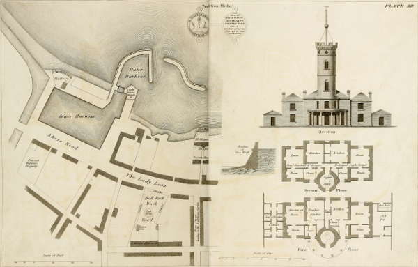
PLAN of the HARBOUR and part of the TOWN of ABERBROTHOCK
PLANS & ELEVATION of the LIGHT KEEPERS HOUSES & SIGNAL TOWER
Drawn by D. Logan
Engd. by W. H. Lizars
PLATE XII.
Pl. XII.
Work-Yard.—The left-hand side of this Plate is occupied with a plan of the harbour of Arbroath, shewing the relative positions of the Bell Rock work-yard and light-keepers’ houses.
Light-Keepers’ Houses.—The other side of the Plate is occupied with a plan and elevation of the light-keepers’ houses; but as the apartments are respectively marked, it seems unnecessary to enter farther into particulars, than to notice that each family has three rooms, with other conveniencies. Connected with this establishment, there is also a signal-room at the top of the tower, represented in the elevation, where a five-feet achromatic telescope is placed upon a stand. On the roof a flag-staff is erected, and here the signals made by the light-keepers at the Rock are watched and repeated. On the opposite side of the small court formed by these buildings, there is a range of houses for stores, and accommodation for the seamen belonging to the Bell Rock Tender. The whole occupies a piece of ground extending to about one-third of an acre. While the works were in progress, the large telescope was placed at one of the attic-room windows of Provost Balfour’s house, which commands a view of the Rock, as may be observed from the Plate.
Sea-Wall.—The diagram laid down on the left of the light-keeper’s houses, represents a section of the wall erected for the protection of the property against the encroachment of the sea. It extends to about 100 feet, and consists of a face-wall of stone from Mylnefield quarry, backed with Arbroath stone, and a granite pavement along its seaward base.
Protection Medal.—The diagram in the central part of this Plate represents the obverse and reverse of the seamen’s protection medal, described at page 209.
Plate XIII. PLANS OF THE SEVERAL COURSES OF THE MASONRY OF THE LIGHT-HOUSE.
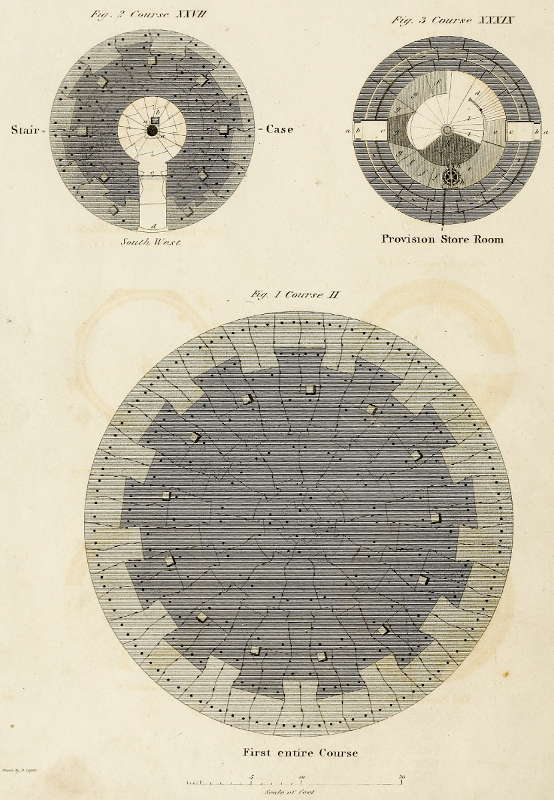
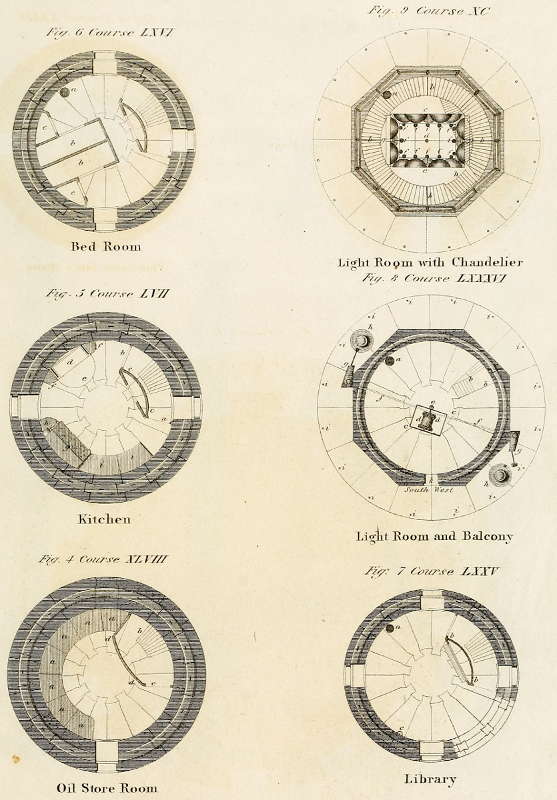
PLANS of the COURSES of the MASONRY of the BELL ROCK LIGHT HOUSE
Drawn by D. Logan.
Engd. by W. H. Lizars
PLATE XIII.
Pl. XIII.
As the ground or imperfect course of the building could not be ascertained till towards the second year’s work, when the site of the Light-house was excavated, this course is represented in Plate XV.
Fig. 1. Plate XIII., is the first entire course, which measures 42 feet in diameter. The dove-tailed method of connecting the solid part of the Light-house here delineated, extends to the height of the entrance-door, as will be further understood by examining the section in Plate XVI. The outward stones of this course are of a lighter shade, being intended to represent the granite blocks, while the central part of a darker shade, represents the sandstone. The thirteen small square or cubical stones in the Plan of this course, shew the upper sides of the joggles, sunk half into the one course, and penetrating half into the superincumbent one, acting as so many steady-pins, calculated to guard against any force tending to affect the fabric horizontally. By tracing the bounding-lines of the stones, from the centre to the circumference, it will be observed, that the whole are connected by means of a system of attachments technically termed Dove-tailing, by which the stones may be said to hook laterally into one another, forming a vertical bond of connection; but it is on the gravity of the materials that the chief dependence is placed for the stability of the fabric. The small circular dots, of which there are four in the centre-stone, and two in each of the others, shew the position of the oaken trenails, measuring 1¾ inch in diameter, and varying in length from 16 to 26 inches, so as to pass through the upper or last laid course, and penetrate 6 inches into the course immediately below. Besides these circular holes, others of an oblong form were cut in the joints, as will also be observed from the Figure. These last were for the reception of wooden wedges, driven in pairs perpendicularly into the joints of the stones, with a view to bring the dove-tailed parts to a uniform bearing, before the joints were grouted with mortar; the bond throughout the building being carefully preserved, by placing the perpendicular joints over the middle of the stones immediately below, being what is technically termed “Breaking-band,”—a system universally attended to in good masonry.
Fig. 2. represents the upper side of the 27th course, or first of the Stair-case, which measures 6 feet 4 inches in diameter within walls, and 19 feet 8 inches over walls. This course is elevated 32 feet 8 inches above the Rock at the foundation of the first stone, as will be seen in the section of Plate XVI. Here the granite casing is discontinued, and sandstone only is in future used. It will be observed, that the same system of dove-tailing is attended to in the stair-case as in the solid: this unavoidably occasioned the working of the stones into very awkward forms, and required the utmost precaution in landing them on the Rock with safety.
The parts of this course which are not shaded, shew the plan of the entrance-door, passage, and circular void of the stair, crossed by the radiating lines of the steps, as also the form of some of the stones of the top of the solid. a a represent the base of a column of cast-iron, which renders the drop-hole for the machinery continuous from the floor of the oil-store down to the level of the passage, and so through the centre of the solid, as shewn in the section Plate XVI.; b is a small stove placed in the stair-case; c is the position of the Inner door, of brass, as shewn in Fig. 2. Plate XIX., the upper part of which is glazed with plate-glass, to preserve the light of the stair-case; d is the position of the entrance-door, which is fashioned agreeably to the circular form of the building, and is strongly bound with the brass-hinges, as also shewn in Figs. 1. and 2. of Plate XIX.
Fig. 3. is the 39th course of the building, and first of the provision-store, and is 45 feet 11 inches above the foundation. This apartment measures 11 feet 9 inches in diameter within walls, and 18 feet over walls. From the floor to the roof the height is 8 feet 7 inches. Here the dove-tailed system, excepting at the end joints, and in the centre stones of the floors, was laid aside. At this level another system of connecting the courses was adopted, by means of a zone or belt, which was raised or worked upon the upper bed of the stones, and fitted to a corresponding groove in the course laid immediately above, as may be seen by tracing the diagrams representing the habitable parts of the house. This zone or belt, together with the horizontal plan of the floors, form the chief distinctive differences between the Designs of the Edystone and Bell Rock.
Fig. 3. The parts in this Figure which are not shaded represent the two windows of this apartment with the landing at the top of the stone stair-case. a a represent the storm-shutters, which will be more fully seen in Plate XIX. b b are the outer glazed windows; c c the inner glazed windows; d the open trap-ladder, with its brass hand-rail, leading to the light-room-store; e e the cast-iron coal magazine; f f f f the water-cisterns, of cast-iron, lined with a mixture of pitch and sand, and containing each 150 gallons; g g g g the four cast-iron magazines, for containing the provision casks, and various implements; h h the machinery, placed on a level with the top of the water-cisterns, for raising the stores from the entrance-door of the building to the Light-house; i i is the hole perforated through the wall for the passage of the chain for lifting the stores, the operation of which will be better understood by examining Plate XVI.; k the cast-iron stage upon which the light-keepers stand when they work the machinery for taking up the stores; l l the cast-iron steps leading to the stage k.
Fig. 4. is a plan of the floor of the light-room store, being the 48th course, which is 55 feet 10 inches above the foundation. This apartment, within walls, measures 11 feet 10 inches, over walls 16 feet 10 inches, and its height is 8 feet 7 inches. The shaded part of the floor marked a a a a a a a, represents the copper oil-cisterns, coated with tin, calculated to contain one whole year’s stock of oil, or about 1100 gallons. This apartment being chiefly occupied with these cisterns, there is only one window in it; b is the trap-ladder, and shews also the manhole, measuring 3 feet in its greatest length and 2 feet in breadth; c the store-room door; d d the position of the oaken pannelled partitions, which separate and inclose the store-room from the stair.
Fig. 5. being the kitchen floor, forms the 57th course, which is elevated 65 feet 8 inches above the foundation. This apartment measures 11 feet 11 inches in diameter, over all 16 feet, and its walls are 8 feet 9 inches in height. This room, in the position of its windows, manhole, and trap-ladder, is similar to what has already been described in reference to Figs. 3. and 4. In Fig. 5, a is the door leading to the apartment below; b the door leading to the trap-ladder of the apartment above; c c the oaken partitions, formed into lockers, which shut off the stair from the apartment; d is the cast-iron kitchen range or fire-place, which stands free and unconnected with the walls, forming a connected piece of pannelled work, extending from the floor to the ceiling; e is a strong cast-iron fender, and also a receptacle for the ashes; f f copper coal-boxes, formed into seats, on each side of the fire-place; g the cook’s table and locker; h the handle of the pump, by which water is raised from the provision-store or the second floor below; i i other lockers, also formed into seats.
Fig. 6. is the bed-room floor, or 66th course of the building, and is elevated 75 feet 8 inches above the foundation; it measures 11 feet 11½ inches in diameter, and over all 15 feet 6 inches; the walls are 9 feet in height. The windows, manhole, trap-ladder, doors, and oaken partition are similar to what have already been described in the floors below; a shews the position of the aperture for the cast-iron funnel leading from the kitchen-chimney through the several apartments to the cupola of the Light-house; b b the bed-frames, forming two bed-places in breadth, which are three tiers in height, reaching from the floor to the roof, and capable of accommodating six persons; c c lockers on each side of the beds, for the use of the four light-keepers.
Fig. 7. the next in order is the floor of the Strangers’-room or Library, being the 75th course of the building, which is 85 feet 11 inches above the foundation. The diameter of this floor is 12 feet, it measures 15 feet over walls, and the height of the roof, at the centre, is 11 feet 1 inch. The walls, windows, and other particulars of this apartment are nearly similar to those formerly described; a is the cast-iron funnel leading from the kitchen-chimney; b b the oaken framed book-case; c the tube through which the machinery-rope is conducted by the side of the walls of the several apartments, to the ceiling of the Provision-store.
Fig. 8. is the Light-room floor, or 86th course of the building, which is elevated 97 feet 9 inches above the foundation; within walls the floor measures 11 feet in diameter, over walls 13 feet 6 inches. The stones of the floor of this apartment, as will be observed, extend from the centre stone to the circumference of the balcony, varying from 7 feet to 7 feet 6 inches in length. The parapet-wall of the light-room, as will be seen from the Plate, has its outward face of an octagon form, but is worked circular within. In the several courses of the parapet, the principle of the zone or belt in the beds of the stones is still continued, and also the dove-tail of the end joints. The Light-room measures from the floor to the top of the stone work, or sole of the glazed sash-frames, 6 feet. a is the circular aperture for the cast-iron smoke-tube leading from the kitchen-chimney; b b is the manhole of this floor, having its landing towards the centre of the apartment, instead of being close to the wall, as in the several floors below. To have formed the length-way of the man-hole of this floor along the wall, would have occasioned the cutting of the stones in the dome-roof of the Library, in a manner hurtful to the strength of the building, which was conveniently avoided by introducing a platt in the ladder, instead of ascending more directly as by the trap-ladders of the floors below; c c is the case of the revolving-machinery, which gives motion to the Lights; d d is the drum or barrel, with its connecting wheels, on which the rope is coiled, from which the weight is suspended; e the position of the upright shaft for supporting the chandelier on which the reflectors are ranged, which is put in motion by its connecting train of machinery. The dotted lines marked f f shew the direction of the grooves cut in the floor for the horizontal shafts, which derive their motion from the machinery, and work the hammers of the two alarm-bells placed on the balcony; g g the bell-hammers with their cases; h h the bells, weighing each 5 cwt., which are tolled during the continuance of foggy or snowy weather; i i, &c. are the screwed batts of brass, forming the fixtures of the balcony-rail; k the Light-room door communicating with the balcony, which measures in the clear 5 feet in height, and 1 foot 10 inches in breadth.
Fig. 9. is a plan of the Lantern, showing the position of the trimming-path, and reflector-frame. The height from the foundation to the sill of the sash-frame is 102 feet 6 inches, and from thence to the lining of the cupola 13 feet four inches. a is the smoke-tube leading from the kitchen to the cupola; b b b b the cast-iron grated trimming-path, on which the light-keepers stand when they trim the lamps; c c the reflector-frame or chandelier, on which three tiers of reflectors are ranged; d the upright shaft; f f, &c. the position of the fountains for the reflector-burners, g g the position of the shades of red-coloured glass, by which the light is distinguished; h the iron trap-ladder communicating with the trimming-path.
Plate XIV. MOVEABLE BEAM CRANE.
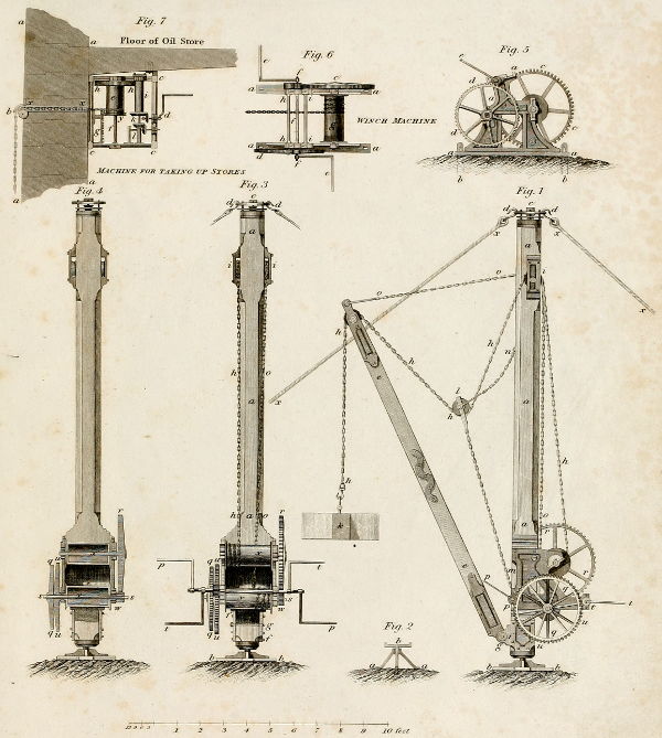
MOVEABLE BEAM CRANE &c.
Drawn by A. Slight
Engd. by A. Wilson
PLATE XIV.
Pl. XIV.
Fig. 1. is an Elevation of the Crane. In cranes of the common construction, the beam is a fixture, and is placed at right angles to the upright-shaft; but in the machine represented in this Plate, its attachment is at the lower extremity of the crane, where it is moveable up and down upon a journal or bolt. This crane is therefore termed a Moveable-beam-crane. The moveable property of the beam, in so far as the writer knows, is new, and possesses the advantage of laying any stone within its range perpendicularly on its site. This, from the dove-tailed form of the stones at the Bell Rock, rendered it essentially useful to this work, to which a crane of the ordinary construction could hardly be said to be applicable. At the Edystone Light-house this operation was performed by means of Triangular-sheers; but, from the greater extent of the Bell Rock works, and their greater depth in the water, such means must have rendered the process of building extremely tedious.
In reference to this Figure, a a a is the upright shaft of the crane; b b the cast-iron foot into which the lower journal of the shaft was stepped; c the cap into which the upper journal works, and into which two of the hooks d d of the four guy-ropes x x x x were entered, for commanding the top of the upright-shaft. From the immersed state of these cranes, while the building was low in the water, a guard-plate was introduced, and bolted to the cap, which laid hold of a collar raised round the journal, to prevent the cap from being unshipped by the waves; e e is the moveable beam, formed and built of two strong pieces of oak timber, connected in the centre by a serpentine row of bolts. This beam was mounted at the upper and lower extremities with strong cast-iron plates; f marks the cast-iron sheers or cheeks, fixed to the bottom of the upright shaft, into which the moveable beam works upon the journal or bolt g.
In order to direct the strain of the main purchase-chain h h h h h h passing over the cheek pulley i fixed upon the shaft, and to prevent its effect from bringing home the moveable beam e e to the upright shaft, a martingale or tail-block l is introduced and made fast to the shaft at m. When the purchase-chain is not in action, the block l is suspended from the small chain at n, which prevents it from falling too low, and thereby deranging the position of the purchase-chain. That the beam may be made applicable to laying the stone marked k, at the foot of the crane, or at the utmost reach of the beam, a chain or purchase marked o o o, is introduced, which also passes over a cheek-pulley i on the opposite side of the shaft. By this additional apparatus the beam is capable of being elevated or depressed at pleasure. The handle marked p p, with its pinion and connecting wheel q q, and larger wheel r r, together with its intermediate pinion, form the main purchase, and exert a force calculated at the rate of about 98 to 1. When a smaller weight was to be lifted, and greater speed wanted, the handle was transferred to the axle s, whose pinion being always in gear with the wheel r r, produced an accelerated motion, with a power in the ratio of 20 to 1; at the same time, the handle t t, with its pinion in action with the wheel u u, worked the beam e e, so as to lay a stone perpendicularly with the greatest facility within any part of its range.