DESCRIPTION OF PLATES. (continued 2)
Reading edition
Fig. 2. is the cast-iron tripod, used as a prop to the moveable beam, when applied as a lever, for lifting the crane; a a a mark the foot, b the cross head, having a stud which works into a circular hole perforated in the top of the tripod. By this simple apparatus, the crane could be moved and shifted either perpendicularly or horizontally, with a facility which added greatly to the conveniency of the operations. When the tripod was applied to use, it was placed under the heel-plate of the moveable beam marked v, and when rested upon it, the beam became a lever of great power.
Fig. 3. is an Elevation of the Working-gear of the Moveable Beam-Crane. a a a is the upright-shaft, as in Fig. 2.; b b the cast-iron foot; c the cap with its guard-plate; d d guy-hooks for commanding the top of the shaft; f f the edges of the sheers or cheeks, for the heel of the moveable beam; g the bolt or journal on which the beam is moveable; h h the purchase-chain; i i the cheek pulleys; o o the moveable beam-chain; p p the two main purchase-handles; q q the smaller wheel of the main purchase; r the greater wheel, with the intermediate pinion w, connected with the axle s of the wheel q q. The handles and pinion t t are connected with the wheel u u, for working the moveable beam-purchase; x is the drum or barrel for the main purchase-chain; y the barrel of the purchase-chain of the moveable beam.
Fig. 4. is a Section, shewing the connection of the purchases for working the beam, and lifting the weight: the axle s, of the lesser wheel q, with its intermediate pinion x of the main-purchase, work through the eye or centre of the wheel u u, and barrel y of the beam-purchase. x and r refer to the corresponding letters in Fig. 3.
Fig. 5. is an Elevation of the Winch-machine. The machines, used for the various purposes of landing the materials and raising them to the top of the building, were framed or made of cast and malleable iron. a a a a are the cheek plates or frames in which the axles of the machinery work. Those employed upon the Rock were fixed down by means of spear-bolts, to four bats, as shewn at b b; but in other situations they were fixed by straps of iron to beams of timber. The cheeks a a a a were connected by means of three strong bolts passing through hollow tubes, which butted against the inner sides of the cheeks and kept them in their places. The large wheel marked c c measures 3 feet 3 inches in diameter, and the smaller wheel d d is 2 feet 6 inches: these, with their respective pinions, of 6 inches in diameter, exerted powers respectively of 20 to 1, and 98 to 1, being of a size similar to the cranes; as one set of wheel and pinion patterns were made to answer the several machines employed at the work. Letter e is one of the handles connected with its axle and pinions, which, at pleasure, is made to work with a double or single purchase, by simply slipping the axle out and into gear with the larger and smaller wheels.
Fig. 6. is a Plan of the Winch-machine. a a a a is the sole of the frame, shewing the bat-holes for fixing it down; c is the large, and d the small wheel, with its axle; e e the handles, with their axle and pinions f f f; letter g is the barrel attached to the axle of the large wheel, with part of the purchase-chain; h h is the axle of the small wheel and intermediate pinion; and i i one of the hollow pipes through which the bolts pass for connecting the two cheeks or frame of the machine together.
Fig. 7. refers to a machine fixed to the walls of the Provision-store, for raising the stores from the railways to the entrance-door, as pointed out in Plate XVI. a a a a a section of part of the walls of the Provision-store, in which a hole x x is perforated, and lined with a copper tube, for the passage of the purchase-chain; b is the pulley, with its case, over which it works; c c c is the frame of the machine; and d the handle, with its bevelled pinion. The distinctive feature of this apparatus is the vertical motion of the barrel, by which it receives and discharges the chain always at the same point; the direction also of the chain may thus be altered almost close to the barrel, which in this case was the chief desideratum. To effect this purpose, the barrel is made to move vertically upon the axle f, by means of a screw y, upon its lower end, which works into a corresponding screw-rack g; in its operation, the wheel h h is worked by the cylindrical upright-pinion of brass, marked i. The two pairs of bevelled wheels, supported upon the small intermediate frame l, are introduced, for applying a double or single purchase, according to the load to be raised.
Plate XV. FOUNDATION-PIT, OR EXCAVATED SITE OF THE LIGHT-HOUSE.
FOUNDATION PIT OF THE LIGHTHOUSE.
Drawn by J. Slight.
Engd. by W. H. Lizars
PLATE XV.
Pl. XV.
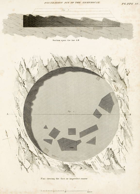
Fig. 1. is a Plan of the site of the Light-house, and of the ground or imperfect course, in readiness for receiving the first entire course of the building, represented in Plate XIII. Fig. 1. The dark shaded figures delineated upon the Plan in Plate XV. represent the stones of the ground-course, consisting of 18 detached pieces, which vary in their forms according to certain irregular holes in the Rock. From the same cause, the stones of this imperfect course vary in thickness from 6 to 18 inches. The situation of the Foundation-stone will be seen from its having the year of our Lord 1808 cut upon it, as noticed at page 237. The four exterior stones, which are cut somewhat of a dove-tail form, are of a lighter shade being granite, while the 14 interior pieces, being of sandstone, are of a darker shade. The dark shading on the northern side of the Plan represents merely the shadow of the higher parts of the Rock round the excavated site of the Light-house.
Fig. 2. is a Section of the Foundation-pit, upon the line A B, varying in depth from 18 inches to 5 feet, representing also the dip or inclination of the strata; while the dotted lines above show the form of the lower part of the Light-house.
Plate XVI. ELEVATION AND SECTION OF THE LIGHT-HOUSE.
ELEVATION and SECTION of the BELL ROCK LIGHT HOUSE.
Drawn by D. Logan
Engd. by W. H. Lizars
PLATE XVI.
Plate XVI.
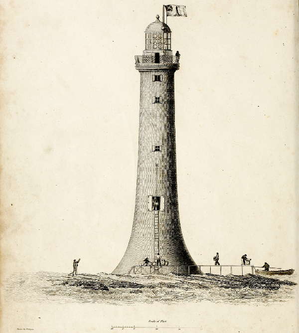
Fig. 1. is an Elevation of the Light-house, with the brazen-ladder leading up to the entrance-door. Part of the Rock and railways are seen, on which several figures are at work, landing stones from a boat, as at low-water of spring-tides. The small aperture bored through the outward wall between the door and the window of the Light-room-store, is for the passage of the chain for raising the stores, as described in Fig. 7. Plate XIV. The two leaves of the entrance-door are shewn folded back upon the walls. The first window above the door seen in this view of the building, is that of the Light-room store; the second is one of the bed-room windows; and the third is in the Library; immediately over this are the cornice and balcony-rail, through which last is seen the Light-room door, with the alarm bells on each side. Through the glazed sashes, the reflectors are seen arranged upon the chandelier, connected with the revolving apparatus. On a level with the lower part of the cupola is the signal-ball. On the ensign-staff a flag is hoisted, with a light-house in the field, used as a complimentary signal in the service of the Northern Light-houses.
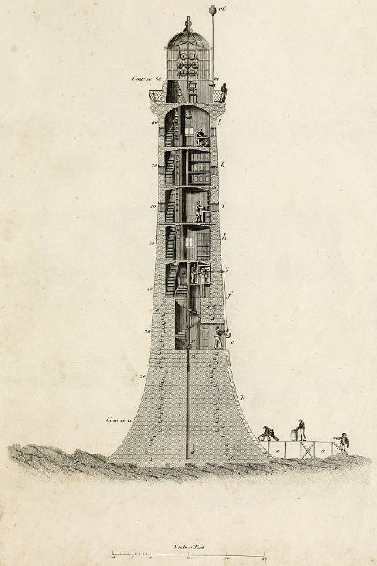
Fig. 2. is a Section of the Light-house, shewing parts of the Rock and ground-course. a a show part of the railways; b the brazen ladder leading to the entrance-door, which is marked c. In the central part of the solid of the building is shewn the cylindrical drop-hole d d, which passes through the centre-stones of each course, and forms part of the range of the machinery-weight. On each side of the drop-hole, throughout the solid, and walls of the stair-case, are seen the stone-joggles e e, &c. as they occur in the several courses, and were noticed in the description of Plate XIII. Figs. 1. and 2. At the entrance-door a figure is represented receiving stores into the house. Immediately behind him, one of the leaves of the inner door, of brass, appears folded back into its recess in the wall, the upper part being glazed with plate-glass, for the admission of light to the stair-case. In continuation of the range of the machinery-weight above alluded to, and extending between the solid and the ceiling of the provision-store, a column of cast-iron, marked x x, passes up through the well-hole of the stair. The provision store, with which the stone stair communicates, is formed by a scarsement of the walls at the level of letter f, on which the water-cisterns, lockers for provisions, and coal magazine, are ranged. Over these a stage or platform of cast iron is erected, on which a figure is seen at work at the machinery for raising the stores from the railways to the entrance-door of the house. The purchase-chain of this machine passes over the pully at g, as described in Plate XIV. Fig. 7.
The next apartment in ascending the oaken trap-ladders leading through the several apartment, is the Light-room-store, marked h, occupied chiefly with 7 copper oil-cisterns, which are strengthened with polished brass bars forming the front into pannels. This, and the several apartments above are partitioned off from the stair with a pannelled framing of oak. The kitchen i, over the store-room, is chiefly occupied with the fire-place, (though not seen in this section), which, with its cast-iron pipe or chimney ascending through the different rooms to the cupola, stand free, or are not embedded in the walls of the house. On the right-hand side of the kitchen a figure is seen at the cook’s table and lockers; and on the left are seen the oaken trap-ladder set close to the wall, and the lockers, by which it is partitioned off from the apartments. A similar arrangement takes place in the bed-room marked h, occupied chiefly with the oaken bed frames, described in Fig. 6. Plate XIII. The apartment marked l is the Strangers’-room or Library, which contains a small collection of books. The furniture is of oak timber, executed in Mr Trotter of Edinburgh’s best style. The walls were painted by Mr Macdonald of Arbroath, in handsomely decorated pannel-work; and from the dome an antique bronze lamp is suspended. The upper apartment m forms the Light-room and Lantern, rendered fire-proof, as every thing is of stone or metal, excepting a small oaken table and chair for the use of the light-keeper on watch; accented m´ is the copper-ball, shown as hoisted for the signal “All is Well.” The reflecting apparatus and revolving machinery with which the Light-room is occupied, will fall to be described under Plate XX.
Plate XVII. BALANCE-CRANE.
BALANCE-CRANE.
Drawn by J. Slight
Engd. by A. Wilson
PLATE XVII.
Pl. XVII.
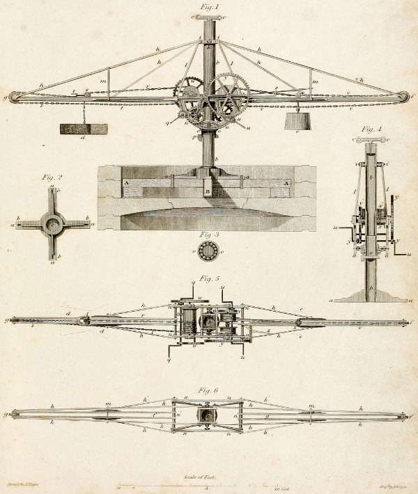
Fig. 1. is an elevation of the Balance-Crane, constructed for building the upper part of the Bell Rock Light-house, when the guy-ropes of the Moveable Beam-crane, became “too taunt,” as sailors express it, or were too near the perpendicular, thereby rendering the machine unstable. To remedy this, the crane alluded to was kept in equilibrium by a back-weight of cast-iron, so adapted as to counteract the varying load upon the working arm or beam. The elevation here represented is the same in principle with that used at the Bell Rock, but differs somewhat in form, agreeably to more recent improvements made in order to adapt it to the erection of the Carr Rock Beacon. a a is the cast-iron foot or socket, into which the upright central column b b is stepped, being a tube of cast-iron put together in convenient lengths, with flush joints, after the manner of spiggot and faucet, fitted by turning and boring. The centre column of this machine might have been carried to any suitable or convenient height, by adding length to length, as the building advanced, without once moving the foot; but at the Bell Rock, not more than three lengths of from 6 to 9 feet were generally in use. c c represent a malleable iron cross-head, which was stepped into the void of the central shaft or column, when the body of the crane was to be elevated. This operation was accomplished simply by hooking the main-purchase and traveller-chains into the eyes c c, when the machinery of the crane was employed with great facility as a locomotive power for lifting itself; d is a stone supposed to be suspended in the purchase-chain; and e is the back-weight or counterpoise, which, at pleasure, was moved horizontally along the balance-beam marked f, consisting of two plates or bars of malleable iron; g is the working-beam, of similar construction; h-h, h-h, h, h, are four of the eight main and secondary suspending ties of malleable iron, applied from above, in order to leave the lower part of the crane unobstructed. This afforded great conveniencey particularly at the Carr Rock, and also at the erection of the Melville Monument of Edinburgh, where the space for the workmen was extremely circumscribed, the shaft of the column not being more than 10 feet 6 inches in diameter towards the top. The main ties h-h, h-h, at the lower extremity, were made fast by the same bolt which passes through the pulleys f and g, while the upper ends were bolted into a collar, which is seen clasping the central column at i i. This collar is fitted with four friction-rollers, one of which is seen at k. l l shew two of the four principal rods or bars of malleable iron for connecting the Crane, and answering the purpose of a king-post to the ties h-h, h-h, of the frame-work; m m mark two of the four braces forming a connection between the main ties and arms or beams of the crane. The cheeks n n n, which contain the train or series of wheels of the crane, are of cast-iron. In the formation of these cheeks they present as little obstruction to the workmen as possible, while, at the same time, they embrace the various journals or axles of the machinery. The upper part is connected by a square framed collar of malleable iron, seen at Fig. 5. fitted with friction rollers, and, like the collar above alluded to, works round the central column. This lower collar is connected with the cheeks of the crane by studs passing through them, and fixed by means of screw-nuts. The lower part of the frame is in like manner connected with the upright shaft, by a collar, which is moveable upon friction-balls of cast-iron, contained in a circular race or chamber o o, a plan of which, shewing the balls, is given at Fig. 3. The whole machine thus fitted, is supported upon the central shaft by means of the cutter or spear-bolt p. The winch handle marked q, is that with which the main-purchase chain r, passing over the pulley s, is worked, from which the stone d is suspended. Connected with the main-purchase, a wheel, marked w, of 30 inches diameter, is worked by a pinion of 5 inches, mounted upon the axle of the handle q, producing a power or force in the ratio of 18 to 1; this power may at pleasure be increased by throwing another pinion on the same axle into gear with the wheel marked n´, of 16 inches diameter.
The handle u u is connected with the main-traveller s, balance-chain v v v, and their traveller x, to which the back-weight e is appended. The main-traveller wheel y measuring 36 inches in diameter, with its pinion of 5 inches marked u, exerting a power in the ratio of 21 to 1, serves to work the main-traveller. On the same axle with the pinion u, is another pinion, working two wheels, as seen in Fig. 4, which gives motion to the balance-traveller. These two combinations of wheels are so arranged, that, by working the small levers m and z, they can with facility be thrown in and out of gear, so as to work the traveller either together or separately. The whole weight of the Balance-crane, here represented as resting upon the oaken beams A A B, on one of the floors, weighed about three tons; but the balance and working beams having latterly been made of malleable iron, and the other parts of the machine considerably lightened, it did not exceed more than two tons in weight when used at the Carr Rock.
Fig. 2. The cast-iron foot of the Crane is necessarily very ponderous, and weighs about half a ton. The toes a a a a extend about 5 feet; b b b b are the bat-holes for fixing it down, in case of its at any time getting off the balance, but, in practice, these bats were seldom applied. When the crane was supported over the void or central holes left in the floors during the progress of the work, the toes were clasped to the oaken beams A A B, formerly noticed, represented as resting on one of the upper floors of the building, B, in Fig. 1., being a cross section of the lower beam, with its levelling-block; c, the socket for the central column, or upright shaft, is 10 inches in diameter at the upper side, and diminishes to 9 inches, that the column may become fixed into it by the pressure of the machine.
Fig. 3. o o, in reference to Fig. 1., represents the collar-chamber, filled with cast iron friction-balls, upon which the body of the machine rested, and traversed horizontally with the greatest facility.
Fig. 4. is a perpendicular section taken across the cheeks and wheels with a view to shew the train of the machine more fully. a a is the foot; b b two lengths of the central column, or hollow cylinder, with their spiggot and faucet joint in the middle, shewing also that the metal is about an inch and a quarter in thickness; c c the cross-head, referred to in Fig. 1.; i i the upper collar, shewing its connection l l with the king-posts or main rods; n n the cast-iron cheeks, with the lower collar, and the chamber for the friction-balls; o the cutter or spear-bolt, which supports the whole machine; u u the traveller handles, the main-purchase handles not being embraced in this section; y y the wheels and pinion of the main traveller; accented y´ y´ the wheel and pinion of the balance-traveller x x. In the central part of this figure, the barrel or drum x of the traveller-chains is seen, and also the middle collar x, with its friction rollers.
Fig. 5. is a plan of the body of the Crane, in reference to Fig. 1. b is a cross section of the central column, seen in connection with the upper collar d d; with a stone suspended from the end of the main-beam; e e the back weight suspended from the balance-beam: f and g the extremities of these two beams; h´ h´ h´ h´ four horizontal braces, extending from the cast-iron cheeks to the middle of the beam. Letters n n n n the cast-iron cheeks of the body; q q the main purchase-handles; r the main-purchase chain; s its traveller; t t the traveller-chain; u u the traveller handles; v the balance traveller-chain; x its traveller; w w the main-purchase wheels; y y the traveller wheels; z the lever, for stopping the main traveller-wheel.
Fig. 6. is a plan of the frame work of this machine: b is the upright column, with the upper malleable iron-collar, shewing its connection with the king-posts l l of Fig. 1.; f and g are the extremities of the main-purchase and balance-beams; m´ m´ the horizontal rods connecting with the main-ties; h h, &c. the main ties; h´ h´, &c. the horizontal braces; n n n n the cheeks or frame of the wheels and machinery, with the two great bolts marked n´ n´, by which the frame was principally connected; these bolts being passed also through the interior ends of the balance and working beams.
Plate XVIII. GENERAL VIEW OF THE WORKS.
Pl. XVIII.
This Plate gives a Perspective view of the Works at the Bell Rock, taken by Carse, at low-water of spring-tide, from on board the Light-house Yacht, in the month of July 1810, at the distance of about half a mile in a southern direction from the Rock, and is here reduced from a picture in the possession of the writer. In the fore-ground a boat is introduced, approaching the Rock with a party of strangers, and another is leaving it, supposed to be receiving orders from a figure on the Rock, who is pointing towards her. In the back-ground, the shipping belonging to the work is introduced, viz. the Tender, a Schooner, and the stone-vessels Smeaton and Patriot, with the Floating-light. In the distance, the hills of Fife and Forfar are seen, but the entrance to the Firth of Tay is intercepted by the beams of the Beacon-house. Between the Light-house and Beacon, or in the direction of the chain and stone suspended from the Wooden-bridge, the ruins of the Abbey of Aberbrothwick are seen. The operation of landing the stones with the sheer-crane at Duff’s Wharf, toward the right, is seen; and also one of the moveable beam-cranes, in a working position, at Pitmilly Wharf, on the left.
The principal lines of the railways, with waggons, and a variety of operations which are in progress, form a very busy scene upon the Rock. On the praam-boat’s deck, toward the left of the picture, Captain Wilson, the landing-master, is represented with a speaking-trumpet in his hand; and at the foot of the Beacon-house, Mr Francis Watt, foreman mill-wright, is supposed to be giving directions about some operations. On a level with the entrance-door of the Light-house, the bridge of communication is situate, and four blocks of stone are seen, in progress of being raised from the railways to the top of the building, viz. one is suspended from the winch-machine upon the bridge, another from the beam projecting out of the window of the Light-room store, a third from the bed-room, and a fourth from the Balance-crane, which last is about to be laid upon the parapet-wall of the Light-room. Here the operations are going forward under the direction of Mr Peter Logan, foreman builder. In the open gallery of the Beacon-house, Mr Dove, the foreman smith, is seen at work, with the smoke of the respective fires of the forge and cook-room. The tackle, distended in a diagonal direction, from the balcony of the Light-house, to the mortar-gallery of the Beacon, shews the mode of raising the mortar-buckets. The figure on the small scaffold suspended from the balcony, shews the method of pointing the walls with Roman cement.
Plate XIX. ENTRANCE-DOOR, WINDOWS, HINGES, AND THUNDER-ROD.
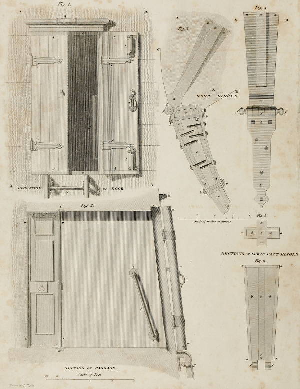
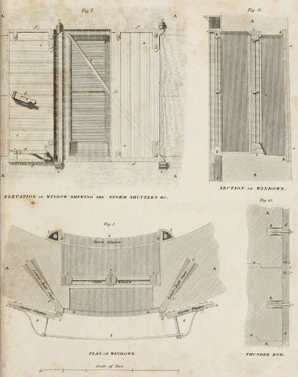
ENTRANCE DOOR, WINDOWS, HINGES and THUNDER ROD.
Drawn by J. Slight
Engraved by R. Scott
PLATE XIX.
Pl. XIX.
Fig. 1. represents part of the outward wall A A A A, and entrance-door, one leaf or half of which is open, and the other shut; a, one of the handles for opening and shutting it, connected with a thumb-latch; b b the bolts for securing the door when shut; c c c c the hinges; d d d d the brass guard-plates at top and bottom of the door, for defending the timber. The door is framed of fir-wood, and measures 6 feet 4 inches in height in the clear, besides the brass-checks upon which it shuts at top and bottom, which are of 2 inches in depth, as shewn at e in Fig. 1., and also by an end view in Fig. 2. The two leaves form a common breadth of 2 feet 10 inches in the clear. A cornice of brass is formed on the lintel of the door answerable to an eaves-drop, in which a friction roller h is placed, for the chain of the crane, with which the stores are raised. The door, when shut, finishes flush with the building, and is therefore of a circular form, framed and double lined, the whole being put together with white-lead paint: each leaf measures 5 inches in thickness at the hinge side, and diminishes to 2½ inches at the meeting edges, as will be understood by examining the section in Fig 3. When the leaves of the door are thrown open, they are kept in their places by catch-hooks of brass, to prevent gusts of wind from shutting them suddenly; f shews a moveable handle or piece of brass rail, within the passage, for laying hold of in stepping off the brazen ladder to enter the house; g shews the upper extremity or highest step of the ladder, which terminates at the sill of the door.
Fig. 2. shews the relative position of the outer and inner entrance-doors, in which a a a is an end view of the former; b b b b a front view of one of the leaves of the inner brass door; e e the outer door check, faced with plates of brass; f the moveable handle or rail, for the greater conveniency of entering the threshold; g the termination and upper step of the brazen-ladder, attached to the building, for communicating with the Rock. h, section of the cornice and friction-roller. The passage being only 2 feet 10 inches in breadth, the rails or moveable handles f, on each side, are made to slide into brass sockets i i, sunk into the walls, and, like the inner door, are flush with the wall when not at use. k k the sockets for the centre-pin hinge of the inner-door.
Fig. 3. is a cross section of one of the leaves of the entrance-door, shewing the position of the brass-case of the hinge-bat, as it lies in the building. A A part of the walls, B B part of the side-walls of passage, C C part of the surface of the outward wall. a a a a is the brass-case, containing the Lewis-bat-tails or palm of the hinge, (described in Plate XI. Fig. 3.); b b b b the working-tails; c c the outside lining; d d the inside lining; e e e the frame-work of the door, with the bolts and nails connecting the hinges; f the joint of the hinge, shewing the journal pin-hole; g the half-check joint of the door.
Fig. 4. represents a front view of the door-hinges, lettered in reference to Fig. 3. a a a a is the brass box or case, which is built into the wall for containing the palm-end of the Lewis-hinge; b b is the exterior or working tail, with its screw bolt and nail holes; f f f the double-joint and slip-pin.
Fig. 5. is a cross section of the Lewis-box on the line A B of Fig. 4. with its dove-tail feathers; a a a a shew the parts of the Lewis-bat b c d, as it lies in the box, which is built into the wall.
Fig. 6. represents a longitudinal section of the box and palm of the hinge, shewing its position, in reference to the cross section in Fig. 5. a a a a is the brass box; b and d are the dove-tailed compartments of the palm; c is the tongue or locking-piece; e the pin hole, perforated in the locking-piece, for drawing the parts of the palm in the event of the joint wearing and requiring to be renewed; f f is the slip pin-hole in the other two parts of the palm of the Lewis. The weight of one of the entire hinges of the door, with its Lewis-tail and brass-box was 56 lb., and consequently the four sets for the door weighed about 2 cwt.
Fig. 7. shews the elevation of one of the windows of the Light-house, with part of the exterior wall marked A A A A; one-half of one of the storm-shutters, marked a a, is closed, and the other marked c c, is open; b is a bar of brass, which folds across the window when the shutters are closed, and is used as a stretcher, for preserving them in their places when opened. It will be observed by comparing the close shutter a a with the open one c c, that they are double or cross boarded; they are also fastened with hammered copper nails; d is the clasp used as a handle, which also locks the shutter; e e e e the ends of the dove-tailed hinges as they appear projecting through the walls; f f f f the working-tails of the hinge, forming at the same time the guard-plate of the shutters, as described in Fig. 1. Letter g, upon the open shutter, shews one of the brackets connected with the stretching-bar b, for keeping them open, as will be better understood by examining the following Figure.
Fig. 8. is a plan of one of the window-sills, and a section of one of the storm-shutters, with part of the walls A A, shewing the position of the Lewis-bat cases; a and c, the storm-shutters in an open state; b the stretching-bar in its place, when the shutters are open; e e the exterior ends of the Lewis-bats, with their cases é é é é, which are built into the wall, and, together with the other parts of the hinge, weigh about 28 lb., or 1 cwt. for each set, being one-half of the weight of the door-hinges; g g the brackets connected with the stretching-bar; h h the check in the wall for receiving the shutters; i i the stiles or framing of the outer-window, which opens in two leaves; k k k the framing and case of the inner window, which slides up and down in one sash; l l the balance-weight of the inner-window.
Fig. 9. is a perpendicular section of one of the windows, shewing the triple mode of shutting them during stormy weather. A A a section of a part of the walls. a a, the storm-shutter; h h the check in the building for its reception; i i the frame of the outer-window; k k the inner-window; l the case into which the inner-window drops when not in use.
Fig. 10. A A is a section of part of the thunder-rod and outward wall. a a shew part of the zones or bond-belts, noticed in Plate VII. Fig. 7., and Plate XVI. Fig. 2.; b b the brass-bats let into the wall, for attaching the thunder-rod with the screws c c, which vary from 2 to 3½ feet apart; d d the thunder-rod, made of the best gun-metal, and weighing at the rate of 7 lb. per lineal foot in the range of the sea, or from the Rock to the entrance-door, and from thence to the Light-room, at the rate of about 4 lb. per lineal foot; e is the joint technically termed Half-checking, by which the pieces, of about 7 feet in length, are connected by two screws at each joint, as shewn in the section. This rod, which extends from the Light-room to the Railways, forms an exterior Conductor, while another, which is not seen here, is connected with the chimney, brazen ladder and railways, and completes the interior conducting process.
Plate XX. BALCONY AND LIGHT-ROOM.
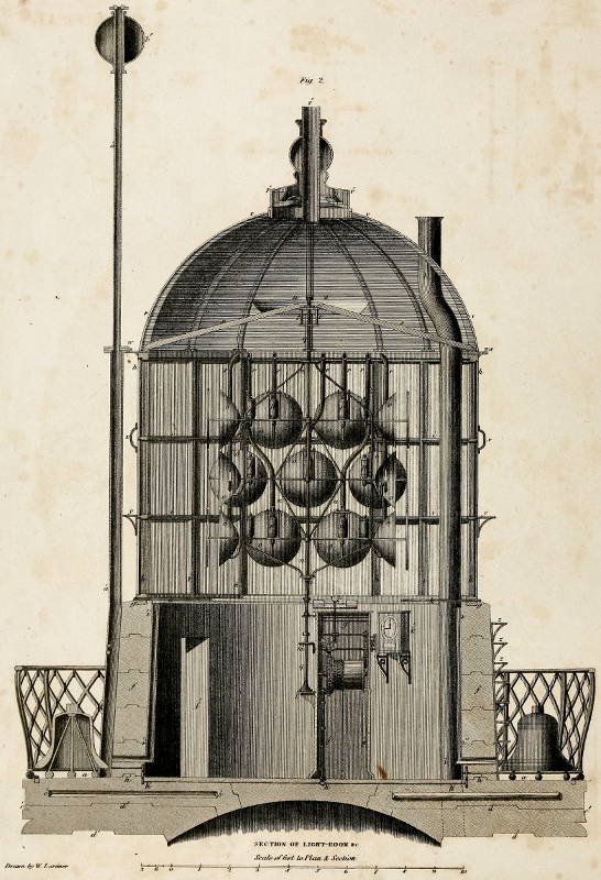
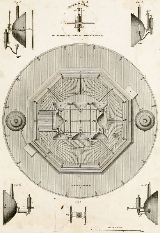
LIGHT-ROOM AND BALCONY.
Drawn by W. Lorimer
Engd. by J. Moffat Edinr.
PLATE XX.
Pl. XX.
Fig. 1. a a represent the Balcony or walk round the exterior of the Light-room; b b, &c. the brass bats, made in the form of the paw of an animal, are used for supporting the balcony-rail; c c the two Alarm-Bells; d d the hammers by which they are tolled, during the continuance of foggy or stormy weather; e e the case for defending the levers which work the hammers; f f f the stone parapet-wall of the Light-room, of an octagon form on the outside, and circular within; g g g the cast-iron sill of the lantern; h h, &c. the angular cast-iron pillars or mullions, formed by the junction of the contiguous parts of two of the sash-frames; i i, &c. the smaller upright bars, forming the astragals or principal divisions of the sash-frames; k k, &c. the grated cast-iron trimming-path; l the smoke-tube, leading from the kitchen through the cupola or roof; m the trap-ladder leading from the light-room-floor to the trimming-path; n n the reflector frame or chandelier, on which are seen 8 of the reflectors marked o o, &c. with their oil-fountains p p, &c. the whole being framed or built upon the moveable upright-shaft q.
Fig. 2. is a section of the dome-roof of the library, the parapet-walls of the light-room, the lantern and its cupola. a a is the balcony, shewing the position of the Alarm-Bells, and cast-iron rail; which last is made in the form of meshes, with a massive coping of brass; f f the parapet-wall of the light-room; g g the cast-iron sill of the lantern; h h, &c. the angular pillars or mullions; i i, &c. the astragals; k k the grated trimming-path; l l the smoke-tube passing through the cupola; n n, &c. the reflector frame, on which 20 reflectors, marked o o, &c. with their fountains p p, &c. are ranged; q q the upright shaft upon which the reflector-frame is built, and which is connected with the revolving-machinery; r r, &c. the copper smoke-tubes from the respective reflectors; s s the cross-bars supporting the upright shaft at t t; and u u a copper receiver for any accidental drop from the upper or central ventilator marked v´ v´ v´, while the letters v v v v mark the exterior line of the cupola; w w the external cornice of the lantern, used as a gutter or eaves-drop, from which the rain-water is conducted off the roof in small pipes to the parapet-wall of the Light-room; x x the handles which the light-keepers lay hold of; and y y the exterior grated path on which they stand when cleaning the outside of the windows; z z z the steps fixed to the parapet of the Light-room and lantern, by which they ascend to the cupola; á á the copper-tube, used as a flag-staff; b´ the signal-ball, hoisted daily at the Light-house, between the hours of 9 and 10 o’clock in the morning, when “All is Well:” The ropes for raising this ball pass over two pulleys fixed in the top of the flag-staff, and are let down through the interior of it: c´ c´ part of the cornice of the building, shewing the mode of connecting the horizontal and perpendicular joints of the Library-roof; d´ d´, &c. shew the zone or bond-belt worked in the beds of the courses, as mentioned in the description of Plate VII. Fig. 7., Plate XVI. Fig. 2., and Plate XIX. Fig. 10.; e´ e´, &c. from the enlargement of the scale, shews more distinctly than any of the other diagrams, the mode in which the horizontal joggling of the joints of the Light-room and other floors of the building is accomplished; f´ the door leading from the Light-room to the balcony; g´ g´ g´ the case and machinery for causing the Reflecting-apparatus to revolve, so as to distinguish this Light from others upon the coast; h´ h´, &c. the connection-rods, with their various wheels of communication, for changing the direction, and giving motion to the Bell-hammers; i´ i´, &c. the brass tubes for supplying fresh air to the Light-room; k´ the Time-piece, set upon brackets fixed in the wall, for regulating the Revolving-machinery, and for the direction of the light-keepers in changing the day and night watches; l´ a bracket of cast-iron attached to the machinery-case, for supporting the foot on which the upright shaft works; m´ the bevelled wheels connected with the interior machinery and upright shaft, which can be thrown out and into gear at pleasure.
In describing the Reflecting-apparatus delineated in Fig. 3., we may notice, that, agreeably to the laws of optics, almost inconceivable effects are produced by the use of these specula, by which portions of a sphere are illuminated, whose radii seem to be proportionate to the elevation of the radiant point, and the particular state of the atmosphere. Taking these conditions into view, the Revolving-light at the Bell Rock has been seen, from an elevated position on the land, at the distance of about 35 miles. According also to observations which have been made upon Sumburgh-Head Light, in Shetland, which is elevated about 300 feet above the medium level of the sea, it has been seen from a ship’s deck at the distance of about 27 miles. Similar effects are also expected to be produced with light refracted through glass-lenses. These, it is believed, are about to be made trial of in the Tour de Corduan, at the entrance of the Garonne, with what are termed Polygonal Lenses, being one large lens, built or composed of a number of small lenses, as suggested by Dr Brewster, in the Edinburgh Encyclopædia, in the year 1811, under the article “Burning Glass.”
Fig. 3. a a a represents one of the reflectors, measuring 25 inches over the lips, in a finished state, as now in use at the Bell Rock and Northern Light-houses in general. They consist of a circular sheet of copper, measuring, when flat, 26¼ inches in diameter; weighing 11½ lb. on an average; and plated with silver in the proportion of 6 oz. to each pound avoirdupois of copper. These plates are formed into the Parabolic curve by a very nice process of hammering, and afterwards set into a bezil or ring of brass; b is the lamp, being an Argand-burner, with a circular wick, of about three-fourths of an inch in diameter. If the parabolic figure of the reflector could be constructed and its form preserved with perfect accuracy, the magnitude of the flame of the lamp employed for its illumination would be of less importance. From certain experiments now in progress, the writer is in expectation that considerable improvements may be introduced, in the construction of reflectors, and that additional modes of distinguishing the Light-houses on the coast will be obtained. c is a cylindrical fountain of brass, which contains 24 oz. of oil, suitable for the consumpt of the lamp for about 18 hours, or equal to its expenditure during the longest night in Shetland. A great improvement upon the Burner-apparatus has lately been introduced into the Northern Lights, by affording the light-keeper an opportunity of cleaning the reflector without the obstruction of the burner: the oil-pipe and fountain of the burner is connected with the rectangular frame d, and moveable in a perpendicular direction upon the guide-rods e and f, by which it can be let down and taken out of the reflector, by simply turning the handle g, as will be more fully understood by examining Fig. 5. In this way, the necessity of lifting the reflector, or deranging its focus, is avoided. Although a properly trimmed lamp, especially upon the Argand principle, does not emit smoke, yet the heat and effluvia arising from it, are sufficient to oxydise or sully the upper part of the reflector: an aperture of an elliptical form, measuring about 2 inches by 3 inches, is therefore cut in the upper part of the reflector, to which the copper-tube h is attached. Letter i, immediately behind the reflector, refers to a cross section of the main-bar of the chandelier or frame on which the reflectors are ranged, each being made to rest upon three knobs of brass, one of which, as seen at k k, is soldered upon the brass band l, that clasps the exterior of the reflector.
To distinguish the Bell Rock Light from others on the coast, as noticed at page 401, it is made to revolve, and to exhibit periodically a bright light of the natural appearance, alternating with a red coloured light. This last effect is produced by means of shades of red glass, one of which, represented at m m, is also set in a brass bezil, and made to slide horizontally upon two rods marked n n, into corresponding sockets, fixed upon the reflector-frame at o, so as to enable the light-keeper to trim the lamp without entirely removing the red coloured shade. In the present aspect of the shade, the rods are drawn out to their full extent; but when set for use, the shade is pushed in till its bezil and that of the reflector are within half an inch of each other.
Fig. 4. is a section of the reflector a a, shewing the position of the burner b, with the glass chimney accented b´ b´, and oil cup b, or receiver for any drop that may fall from the lamp. The letters c, d, f, and g, in reference to the corresponding letters in Fig. 3., shew the oil-fountain in its place when the burner is in use.
Fig. 5. has reference to the apparatus for moving the burner up and down, so as to admit freely of the reflector being cleaned. In the present position, c, the fountain, is moved partly down; d d, &c. shows the rectangular frame on which the burner is mounted; e e the elongated socket-guides; f the rectangular guide-rod, connected with the sockets on which the perforated check-handle g slides; accented c´ is a cross section of the oil-pipe, where it joins the valve of the fountain.
Figs. 6, 7, and 8. These three diagrams represent a different mode of withdrawing the burner from the reflector, for the conveniency of cleaning it. In Figs. 3, 4, and 5., this is supposed to be done by a perpendicular motion of the burner; but in Figs. 6, 7, and 8. it slides horizontally. Fig. 8. is a horizontal section of the reflector a a a, and its apparatus, the letters in which correspond with those of Figs. 3, 4, and 5. The advantages attending this mode, are the rendering of the apparatus more steady, by its having two points of support upon the bars i i and k k; while its motion is more direct. The part of the reflector cut out for the admission of the burner in this case, being that which is partly intercepted by it, little of the reflecting surface is thus lost; and this mode may therefore be considered an improvement upon the perpendicular manner of lifting and lowering the burner.
FRONTISPIECE.
Pl. XXI.
This scene, which is intended to represent the Bell Rock after a storm at north-east, will hardly admit of any adequate description, from the evanescence of the form of the waves upon these occasions. It is, however, founded upon observations made at the Light-house, between the years 1810 and 1822, or during twelve successive winters. The great rise of the sea during a gale, as delineated in the Vignette to the Narrative of the Edystone Light-house, being so surprising, the writer was at much pains to ascertain the effect also at the Bell Rock; and the maximum height of the sprays hitherto observed has been about 105 feet, or as high as the central part of the Light-room windows.
Mr Andrew Masson, an artist who in early life had been at sea, having expressed a desire to reside in the Light-house for some time during winter, that he might observe the waves in a storm, was readily furnished with an opportunity. He went there in the month of December 1816, and remained for six weeks and four days, when he produced various sketches of the appearances which he witnessed; and Mr Macdonald, noticed at page 519, made several outlines from actual observation, in the winter of 1820. All of these were put into the hands of Mr Turner, Royal Academician; who gave the very spirited drawing from which Mr Horsburgh, an artist of much promise, has succeeded in producing the striking representation in the Frontispiece. The writer has also the pleasure of acknowledging the obligations he owes to Mr Williams, author of Views in Greece, for his friendly advice and assistance.
It may here be remarked, as not a little surprising, that while the sea is running nearly to the height represented in the Frontispiece, the entrance-door of the Light-house, or at least one of its leaves, may nevertheless be left open; and the portion of water which on these occasions makes its way into the passage, is found to be very trifling. This is owing to the fortunate position of the door; for, while the sprays on the eastern side fly with the quickness of lightning to the top of the house, the waves separate below, and are sent round the building with such force, that their collision upon the lee-side produces the wonderful appearance in the picture; where a downy spray, white as snow, rises at some distance from the house, to the height of 20 or 30 feet above the medium surface of the sea, and comes in minute particles upon those within the entrance-door, producing a sensation as if dust were falling upon them.
VIGNETTE OF SECOND TITLE-PAGE.
Pl. XXII.
The night scene of the Bell Rock Light-house, in the Vignette of the Second Title-page, was drawn by Miss Stevenson, from a sketch by the masterly hand of Mr Skene of Rubislaw. To Miss Stevenson, also, as an amanuensis, the writer takes this opportunity, with parental affection, of acknowledging his obligation for almost the entire manuscript written to his diction. The reader will be gratified to find, in connection with this Vignette, inserted at page 64., a fac-simile of the handwriting of Sir Walter Scott, Bart. in the expressive and beautiful lines which he wrote in the Album kept at the Light-house, as noticed at page 419.
Plate XXIII. DESIGN FOR A LIGHT-HOUSE, SUGGESTED UPON VISITING THE WOLF ROCK SITUATE EIGHT MILES S. S. W. FROM THE LAND’S-END.
SKETCHES of a NEW DESIGN for a LIGHT HOUSE.
Drawn by G. C. Scott
Engd. by J. Moffat Edinr.
PLATE XXIII.
Pl. XXIII.
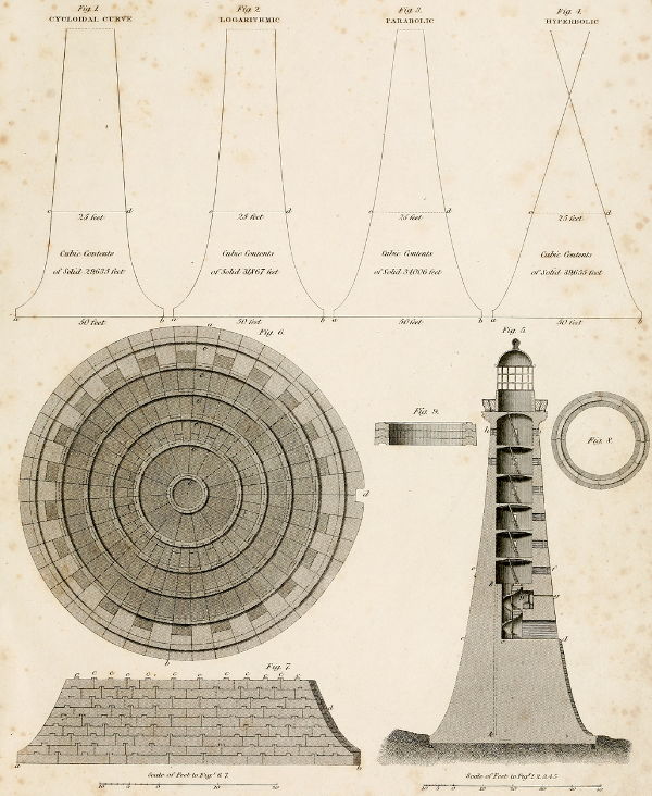
In the range of aquatic buildings applicable to the purposes of a Light-house, which the writer has examined, he was forcibly struck with the magnitude of the Tour de Corduan, on the French coast. This magnificent edifice measures about 145 feet in diameter at the base, and 150 feet in height. Its cubical contents may perhaps be stated at the immense quantity of 339,432 feet; of which the basement alone forms about 200,000 feet. This building has undergone considerable alterations since its completion in the year 1609, as appears from Belidor’s Architecture Hydraulique, tom. ii. At the time of its alteration from a coal fire to an oil light with reflectors, the upper parts in particular seem to have been greatly simplified, by the removal of several of its exterior ornamental appendages.
The Edystone Light-house, owing to the smallness of the rock, as appears from Mr Smeaton’s Narrative of this celebrated building, measures only 26 feet in diameter, at the level of the first entire course; but if there had been space on the Rock for extending it equally on all sides, the ground-course, according to the curve of the outward walls, and the position of the foundation-stone, would have measured 32 feet in diameter. The height of the cupola of the Edystone Light-house is 90 feet, and the cubical contents of the masonry is about 13,147 feet. The Bell Rock Light-house, measures 42 feet in diameter at the base; its height, from the foundation to the cupola, is 118 feet; and the cubical contents of the masonry, as appears from the Table in Appendix, No. VI. is 28,530 feet.
Though the design represented in Plate XXIII., is more or less applicable to several situations upon the coast, yet the writer, in making this Sketch, had special reference to the Wolf Rock, which, as noticed at page 423, he visited in the Orestes sloop of war, commanded by Captain Smith. The extreme dimensions of the upper surface of this rock are about 115 feet, by 90 feet. It is not liable to be covered by the ordinary rise of the tide, though little of it appears above water in spring-tides. The Rock consists of grey porphyry, and is extremely hard. Its outline is somewhat uniform, and the depth of water in its vicinity is from 20 to 40 fathoms. The dangerous position of this reef, in reference to the navigation of the British Channel, led to the proposition of having a Light-house upon it many years since. The erection, however, was ultimately made upon the Long-Ships Rocks, lying about one mile off the Land’s-End.
With the construction and dimensions, therefore, of the Light-houses above alluded to in view, the design delineated in this Plate is given, as the result of the writer’s knowledge and experience on subjects of this kind. Without, however, entering into particulars as to the mode in which such an operation should be conducted, he merely notices, in reference to the various curves delineated in Figs. 1, 2, 3, and 4. as applicable to Light-houses upon sunken rocks, that he prefers the curve of the diagram represented in Fig. 3., as the outline of a building for a situation like the Wolf Rock.
Fig. 1. is formed by the supposed revolution of the cycloidal curve round the axis of a building, whose base is 50 feet, and which, at the entrance-door or top of the solid, measures 25 feet in diameter; the lines produced beyond these dimensions, which would form the habitable part of the Light-house, being tangents to the curves below. Between the base a b, and its parallel c d, this Figure contains 29,635 cubic feet.
Fig. 2. is in like manner formed by the revolution of the logarithmic curve round the axis of a building of similar dimensions at the base and top of the solid with Fig. 1., and contains 31,867 cubic feet.
Fig. 3. is obtained by the revolution of a parabola round the axis of the supposed building. The contents of the solid part, ascertained as in the two former Figures, is 34,006 cubic feet, being 4,371 cubic feet more than that of the cycloidal curve, and 2,139 cubic feet more than in the logarithmic curve.
Fig. 4. is formed by the revolution of the hyperbola between the two parallels a b, and c d, and contains 39,655 cubic feet, or 5,649 cubic feet more than the parabola. But, from the divergent nature of this curve, it is not applicable to the purposes of a Light-house tower, in its pure or simple form.
Fig. 5. is the section of a design formed by the revolution of the parabola round the axis of a building, as its asymptote, whose base a b, measures 56 feet in diameter, and parallel c d, at the top of the solid, is 36 feet; and height to the entrance-door, 35 feet. The contents of this Figure between these parallels is calculated at 45,000 cubic feet; but the whole of the masonry of the design is estimated at 70,624 cubit feet. Its general features may be stated as similar to those of the Edystone and Bell Rock Light-houses, the parts being only enlarged and the parabolic instead of the logarithmic curve, adopted for its outline. In this design, the parabolic curve is continued from the basement to the cope-stone of the Light-room, exclusively of the projection for the cornice and balcony. The masonry is intended to be 120 feet in height, estimating from the medium level of the sea, of which the solid, or from the foundation to the entrance-door, forms 35 feet, the stair-case 25 feet; and the remaining 60 feet of its height is occupied with six apartments, and the walls of the Light-room. In the stair-case a recess is formed for containing the machinery, for raising the stores to the height of the entrance-door; here a small hole, marked g g, is perforated through the building, for the admission of the purchase-chain. The thickness of the walls immediately above the solid, marked c c, is 12 feet; at the top of the stone staircase or level e f, they are 8 feet, and where the walls are thinnest, as at h i, immediately under the cornice, they measure 2 feet. k k represents a drop-hole formed in the courses of the stair-case and solid, for the range of the weight of the machinery of a revolving Light. The ascent to this building, as at the Bell Rock, is intended to be by an exterior stair or ladder of brass, and the interior communication between the several apartments by means of flights of circular oaken-steps.
Fig. 6. represents the first entire course of this design, drawn to a scale double the size of the former Figure, and shows the manner in which the courses are proposed to be built or connected with each other. In every building of this kind, it is proper that two or more of the lower courses, according to the situation and circumstances of the rock, should be sunk or imbedded in it. Since the erection of the present Light-house on the Edystone, the practice of dove-tailing and trenailing stones in water-buildings has been occasionally followed; and there can be no doubt that in some instances it is attended with advantage. But it is also true, that, independently of the extra quantity of rock and workmanship required, the stones are thereby greatly weakened, and rendered much more difficult to be landed in safety in such situations, and that there is often more apparent than real utility in cutting them agreeably to this system of building, as the great bond of the fabric still resolves itself into the gravity of the materials. It may likewise be noticed, that, unless in very peculiar circumstances, the process of trenailing stones newly laid in mortar ought to be avoided, as it becomes necessary to bore holes into the course immediately below, which is apt to break the bond of the mortar by the tremulous motion of the jumper or chisel and hammer.
To avoid these disadvantages, and more effectually to preserve the square or simplest form of the stones, it is proposed, in this new design, to adopt the same mode throughout, that was followed with the courses of the void or habitable part of the building at the Bell Rock, viz. to have zones or joggle-belts worked on the upper beds, and corresponding grooves cut into the under beds, of all the stones. In the plan represented in this Figure these zones are intended to be 1 foot in breadth, and 1½ inch in depth or thickness, forming the concentric rings, marked c c c c c c, which become so many girths to the course, superseding the necessity both of the dove-tailing system, and of the cubic joggles described in Plate XVI.
In tracing the general aspect of Fig. 6., it may be observed that the outer circle of stones is more lightly shaded, being intended for granite, while the hearting or interior part is of a darker shade, as descriptive of sandstone. The whole course of the building here represented, is uniformly simple, and when laid in its place, no mode of attachment can be conceived more effectually to add to the strength and connection of the fabric than these circular belts. Letter d refers to the recess worked in the outward wall of the solid, measuring 2 feet in breadth and 1 foot in depth, for the reception of a flight of brazen-steps for ascending to the entrance-door, instead of the greater projection of the spiral-formed stair delineated in Plate VII., Fig. 6., or the uncertain means of communication by a rope-ladder. The recess alluded to on the outward wall is worked with a small projection, which gradually falls into the circle of the building, without presenting any abrupt face to the waves. A stair of this description, upon a sloping wall, is ascended with great ease.
Fig. 7. is a section of part of the solid of the building, of which a b is the foundation course, and, in reference to Fig 6., letters c c, &c. correspond with the zones or joggle-belts; d d, shew a section of part of the brazen-ladder, answerable to the purposes of a stair, and a pair of skids, for preventing the joints of the building from being injured in taking up stores to the Light-house. This ladder may also be applied as a part of the thunder-rod, as is the case at the Bell Rock.
Fig. 8. is a plan of an entire course of the void or habitable part of the Light-house, showing one of the joggle-belts of the bed-joints. The form of joggle for the end-joints here shewn is also simple, and suited for preserving the strength of the materials more entire than the method of dove-tailing.
Fig. 9. is a section of three courses of the void of the building, showing the connection of the bed-joints.
FINIS.
P. Neill, Printer.