EXPERIMENTS ON RETAINING WALLS AND PRESSURES ON TUNNELS.
Reading edition
By William Cain, M. Am. Soc. C. E.
With Discussion by Messrs. J. R. Worcester, J. C. Meem, and William Cain.
The most extended experiments relating to retaining walls are those pertaining to retaining walls proper and the more elaborate ones on small rotating retaining boards. The results referring to the former agree fairly well with a rational theory, especially when the walls are several feet in height; but with the latter, many discrepancies occur, for which, hitherto, no explanation has been offered.
It will be the main object of this paper to show that the results of these experiments on small retaining boards can be harmonized with theory by including the influence of cohesion, which is neglected in deducing practical formulas. It will be found that the influence of cohesion is marked, because of the small size of the boards. This information should prove of value to future experimenters, for it will be shown that, as the height of the board or wall increases, the influence of cohesion becomes less and less, so that (for the usual dry sand filling) for heights, say, from 5 to 10 ft., it can be neglected altogether.
The result of the investigation will then be to give to the practical constructor more confidence in the theory of the sliding prism, which serves as the basis of the methods to follow.
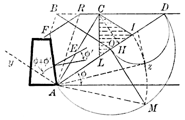
Fig. 1.
As, in the course of this investigation, certain well-known constructions for ascertaining the pressure of any granular material against retaining walls will be needed, it is well to group them here. The various figures are supposed to represent sections at right angles to the inner faces of the walls with their backings of granular material. In the surcharged wall, Fig. 1, produce the inner face of the wall to meet the surface of the surcharge at . It is desired to find the thrust against the plane, , for 1 lin. ft. of the wall. Draw through , the foot of the wall, making the angle of repose, , of the earth with the horizontal and meeting the upper surface at . Since any possible prism of rupture, as , in tending to move downward, develops friction against both surfaces, and , the earth thrust on the wall will make an angle, , with the normal to , where is the angle of friction of the earth on the wall. As the earth settles more than the wall, this friction will always be exerted. Again, as the wall, from its elasticity and that of the foundation, will tend to move over at the top on account of the earth thrust, the earth, with its frictional grip on the wall, will tend to prevent this, so that the friction is exerted downward in either case, and the direction of the earth thrust, , on is as given in Fig. 1.
However, if , a thin slice of earth will move with the wall, and the rubbing will be that of earth on earth, so that in this case must be replaced by . This rule will apply in all cases that follow, without further remark, wherever is mentioned.
Now draw , making the angle, , with , as shown; then draw parallel to , to the intersection, , with produced. From a parallel to is constructed, meeting at .
Since theory gives the relation: , two constructions follow, by geometry, for locating the point, . By the first, a semicircle is described on as a diameter; at the point, , a perpendicular is erected to , meeting the semicircle in ; then is laid off equal to the chord, . By the second construction, a semicircle is described on as a diameter, a tangent to it, , from is drawn, limited by the perpendicular radius, and finally is laid off equal to .
The point, , having been thus found by either construction, draw parallel to to the intersection, , with . is the plane of rupture. On laying off , and dropping the perpendicular, , from on , the earth pressure, , on is given by , where is the weight of a cubic unit of the earth; otherwise, the value of is given by times the area of the shaded triangle, . If the dimensions are in feet, and is in pounds per cubic foot, the thrust, , will be given in pounds.
Fig. 2. Fig. 3.
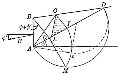
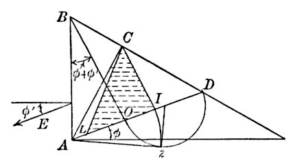
In the Rankine theory, pertaining, say, to Fig. 2, the earth thrust on a vertical plane, , is always taken as acting parallel to the top slope. This is true for the pressure on a vertical plane in the interior of a mass of earth of indefinite extent, but it is not true generally for the pressure against a retaining wall. Thus, when , Fig. 2, is horizontal, Rankine’s thrust on would be taken as horizontal, which entirely ignores the friction of the earth on the wall. The two theories agree when and slopes at the angle of repose, in which case, as is parallel to , there is no intersection, . It is a limiting case in which, to compute the thrust, can be laid off from any point in , on drawing parallel to , etc. As approaches the natural slope, the point, , recedes indefinitely to the right, and it is seen that the plane of rupture, , approaches indefinitely the line, , or the natural slope. This limiting case, on account of the excessive thrust corresponding, will be examined more carefully in the sequel.
If the height of the wall, , in feet, and the weight of a cubic foot of earth, in pounds, then when , and the surface , Fig. 2, slopes at the angle of repose, the earth thrust, in pounds, is given by the equation:
If, however, is not equal to , then is directed at the angle, , to the normal to the wall, and the thrust is:
The foregoing constructions, and the corresponding equations, are all derived from the theory of the sliding prism. The wedge, , Figs. 2 and 3, is treated as an invariable solid, tending to slide down the two faces, and , at once, thus developing the full friction that can be exerted on these faces. In the case of actual rotation of the board, , it is found by experiment that each particle of earth in the prism, , moves parallel to , each layer parallel to moving over the layer just beneath it.
A similar motion is observed if the board, , is moved horizontally to the left. However, in the first case (of rotation) the particles at do not move at all, whereas in the second (of sliding motion) the particles about move, rubbing over the floor, which thus resists the motion by friction. A thrust, thus recorded by springs or other device, in the case where the wall moves horizontally, would give an undervaluation at the lower part of and consequently the computed center of pressure on would be too high. On that account, only the experiments on rotating boards will be considered in this paper.
The theory of the sliding wedge, however, is justified, because no motion of either kind is actually supposed. The wedge, , is supposed to be just on the point of motion, it being in equilibrium under the action of its weight, the normal components of the reactions of the wall, and the plane, , and all the friction that can be exerted along and . These forces remain the same, whatever incipient motion is supposed. The hypothesis of a plane surface of rupture, however, is not exactly realized, experiment showing that the earth breaks along a slightly curved surface convex to the moving mass. For the sake of simplicity, the theory neglects the cohesion acting, not only along , but possibly to a small extent along . This additional force will be included in certain investigations to be given later.
These preliminary observations having been disposed of, the results of certain experiments on retaining walls at the limit of stability will now be given.
Fig. 4. Fig. 5. Fig. 6. Fig. 7.
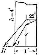
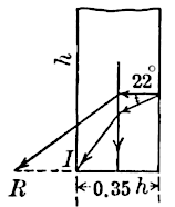
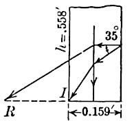
Figs. 4, 5, 6, and 7 refer to vertical rectangular walls backed by sand, except in the case of Fig. 5, where the filling was macadam screenings. The surface of the filling was horizontal in each case. To give briefly in detail the quantities pertaining to each wall, the following symbols will be used:
and are positive when the resultant on the base strikes within the base, otherwise they are negative.
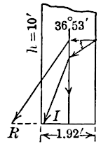
Fig. 4 represents Lieut. Hope’s wall of bricks laid in wet sand: , , , , . It was 20 ft. long, and was backed by earth level with its top. , . The overhang, at the moment of failure, was probably 4 in. Including this, .
Fig. 5 shows Baker’s wall of pitch-pine blocks, backed by macadam screenings, the level surface of which was 0.25 ft. below the top of the wall; , , , , , , the assumed angle of friction of timber on stone, , .
Trautwine’s experimental wall is shown in Fig. 6. Only the ratio of base to height, 0.35, was given by the author, but J. C. Trautwine, Jr., Assoc. Am. Soc. C. E., assures the writer that the walls were probably 6 in. in height, though certain notes refer to walls varying from about 4 to 9 in. , , , (assumed) , , .
The wall of Curie, Fig. 7, was of wood coated on the back by sand, so that . Also, ft., ft., , , .
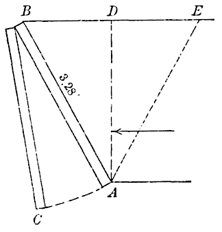
Fig. 8.
These walls were all at the limit of stability, and the first two are of appreciable height, 10 ft. and 4 ft., respectively.
The figures show that the theory, including the whole of the wall friction, agrees fairly well with experiment, but that the Rankine theory does not thus agree. In both theories, the thrust, , is supposed to act at one-third of the height from the base of the wall to the surface of the filling; but, in the Rankine theory, this thrust is assumed to act horizontally, whereas, in the other theory, it is supposed to act in a direction making the angle, , below the normal to the wall.
On combining the thrusts with the weight of the wall, as usual, the resultant strikes the base produced, at in the first case (Rankine theory), but at in the second case. Figs. 4 to 7 present a striking object lesson as to the inaccuracy of the Rankine method of treating experimental retaining walls.
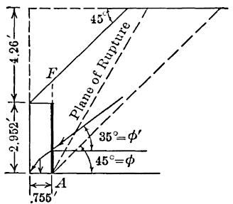
Fig. 9.
The retaining board, 1 m. square, was coated with sand, so that for damp sand. Hence, for a horizontal thrust on , the plane of rupture (which bisects the angle between the vertical and the natural slope) makes an angle of with the vertical. The board, , was set at this angle to the vertical, sand was filled in level with the top, and it was found that the structure was at the limit of stability when m. In the meantime, however, the sand had dried out, so that was ; hence, strictly, the construction of Fig. 1 (for earth level with top of wall) applies; but, as the results can only differ inappreciably, the thrust on , acting horizontally, was computed for and combined with the weight of sand, , and the weight of structure, both acting through their centers of gravity, to find the resultant on the base, . It was found to cut it 0.11 of its width from the outer toe, ; therefore .
In the next experiment, the angle, , was 55°, m. and . Pursuing the same method, it is found that , or the resultant on the base passes practically through . The third experiment was on a smaller retaining board. Here m., , , and .
In Fig. 9 is shown a surcharged wall of Curie’s, just at the limit of stability, having ft., ft. and the level upper surface of the surcharge being 4.26 ft. above the top of the wall. The surcharge extended over the wall at the angle, , corresponding to damp sand. Experiment gave . The wall was of brick in Portland cement. The ratio, . It was found, using the construction of Fig. 1, that taking the thrust, , as acting 1.24 ft. above the base, or at one-third of the height of the surface, , that ; and further, that if acts 1.303 ft. above the base, the resultant on the base passes exactly through the outer toe of the wall.
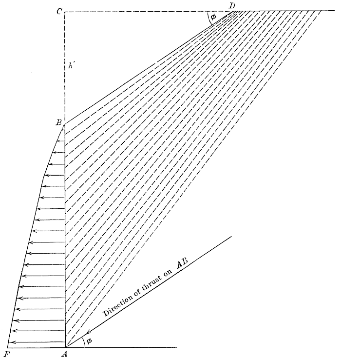
Fig. 10.
As the true position of the center of pressure on a surcharged wall has never been ascertained, as far as the writer knows, he has made a number of constructions, after the method illustrated in Fig. 1, in order to find it.
In place of making the construction for the special case above, it was thought that the results would be more generally useful if the natural slope was taken with a base of 3 and a rise of 2, and , therefore . The wall, , Fig. 10, was taken vertical and 20 ft. high. The surcharge sloped from at the angle of repose to a point, , 10 ft. above , from which point the surface of the earth was horizontal. The face of the wall, , was divided into twenty equal parts, 1 ft. each; and, by the construction of Fig. 1, the thrusts (inclined at the angle, , below the normal to the wall) were found for the successive heights of wall of 1, 2, 3, ... 20, ft., respectively, taking the weight of 1 cu. ft. of earth equal to unity. The successive planes of rupture are shown by the dotted lines in Fig. 10. On the original scale (2 ft. to 1 in.), the upper plane of rupture (for a height of wall = 1 ft.) was found to pass slightly to the right of .
On subtracting successive thrusts, the thrusts on each foot of wall were obtained. These were plotted as horizontal ordinates at the center of each foot division of the wall, and the “peaks” were slightly rounded off, as shown on the figure. Since, with all care, mistakes amounting to 1% of the total thrusts can easily be made, it was proper to adjust the results in this manner to give the most probable unit pressures on the successive divisions of the wall. The centers of pressure, for heights of the wall varying from 5 to 20 ft., were easily obtained by taking moments about some convenient point; the results are given in Table 1.
Call the height of wall, measured from downward, and , the height of surcharge above the top of the wall; also, let the ratio of the distance from the foot of the wall considered to the center of pressure, to the height of the wall. The values of , for various ratios, , are given in Table 1.
TABLE 1.
0.3331.000.364
......0.750.364
2.000.3530.500.364
1.500.356......
1.250.3600.000.333
1.110.362
It is seen, as diminishes, that increases, until for , the maximum value for , 0.364, is attained and remains the same up to , after which it probably diminishes, because, for , .
When some other flatter slope is given to , doubtless these values of will be altered, but, for the case supposed, they should prove serviceable in practice.
Although the earth thrusts on successive portions of are really inclined at below the normal to , they are laid off here at right angles to it, so that the area, , is equal to the total thrust on . If the unit pressures varied as the ordinates to the straight line, , as for a uniformly sloping earth surface, then, as is well known, . The area to the left of gives the excess thrust which causes to exceed .
Making use of the results of the table as approximately applicable in the foregoing example (Fig. 9), and taking the center of pressure on as above the base, the resultant there is found to pass 0.02 outside of the base, therefore . This experiment on a surcharged wall, of the kind shown, is particularly valuable as being the only one of which any account has been given, as far as the writer knows.
Recurring once more to Fig. 10, it may be recalled that some authors have assumed the unit pressures on to vary as the ordinates to a trapezoid, so that the unit pressure at was not zero (as it should be), but an amount assumed somewhat arbitrarily. In particular, Scheffler derived in this way as an upper practical limit, and used it in making tables for use in practice.
A remark must now be added (relative to all the experimental walls previously mentioned, except Trautwine’s), that the friction of the backing on the sides of the box in which the sand was contained has been uniformly neglected. Where the wall is long, this can have little influence, but where the length is not much greater than the height, as in the experiments, this side friction becomes appreciable.
Darwin, as well as Leygue, endeavored to estimate the amount the full thrust (with no side friction) was reduced, by experimenting with sand behind a retaining board, or wall, enclosed in a box as usual, when a partition board was placed perpendicular to the wall and centrally in the mass, and comparing results with those found when the partition board was omitted. Leygue thus found, for walls having a length of twice the height, that the true or full thrust was diminished about 5% from the side friction, for level-topped earth, and as much as 15% for the surface sloping at the angle of repose. If this is true, then the experimental walls just considered would have to be thicker to withstand the actual thrust; or, to put it another way, for the given thickness, the theoretical thrust, including the side friction, would have to be made (as a rough average) about 5% less for the level-topped earth and (roughly) 15% less for the earth sloping at the angle of repose. From the figures it is seen that this will modify the results but slightly, not enough to alter the general conclusion that the theory advocated (including the wall friction) is practically sustained by the experiments, and that the Rankine theory is not thus sustained.
Trautwine’s wall consisted of a central portion of uniform height, from which it tapered to the ends, the upper surface being at the angle of repose for the tapered ends. In this case no side friction was developed. The results agree in a general way with the others.
In the many experiments on high grain bins, the enormous influence of the friction of the grain against the vertical walls or sides of the bin has been observed. In fact, the greater part of the weight of grain, even when running out, is sustained by the walls through this side friction. This furnishes another argument for including wall friction in retaining-wall design.
In connection with this subject, it may be observed that many experiments, made to determine the actual lateral pressure of sand or its internal friction angle, are inconclusive, because an unknown part of the vertical pressure applied to the sand in the vertical cylinder or box was sustained by the sides of the cylinder or box. The ratio of lateral to vertical pressures, or the friction angle, cannot be precisely found until the proportion of the load sustained by the sides of the containing vessel has been ascertained experimentally. The writer is of the opinion that the best experiments to aid in the design of retaining walls are those relating to the rotation of retaining walls or boards. The few given herein are the best recorded, though some of them were on models which were too small. In fact, for the small models of Leygue and others, the effect of cohesion is so pronounced that some of the results are very misleading.
The value of was found by weighing: For the dry sand it varied from 0.79 to 0.65, for heights of the sand in the box varying from 1.2 to 3.5 in. For the damp sand and fresh earth (slightly moistened and slightly rammed) which can stand with a vertical face for the height of the box, the filling was loosened by many blows on the box, and was taken equal to 1.
Three suppositions were made: (1) that both cohesion and friction acted at the same time before motion; (2) that friction alone acted (); (3) that cohesion alone acted ().
The results for various heights of sand in the box are given in Table 2.
TABLE 2.
(1)(2)(3)
Dry sand70.700.80 to 0.9626 to 56
Wet sand400.851.20 " 1.9073 " 133
Very wet sand311.702.00 " 2.40107 " 226
Fresh earth901.632.60 " 4.40150 " 242
The values of are given in kilogrammes per square meter. It is seen that suppositions (2) and (3) give discordant results, whereas (1), for each kind of filling, gave identical values of and of for various heights; hence it may fairly be concluded that, before motion, cohesion and friction both acted at the same time. As to the high values found for , for the coherent fresh earth, Leygue states that Collin found, by an independent method, for clayey earth and clay of little consistency, and , respectively. As a further verification of the values of and given in (1), it is found that, on using them in the formula for computing the height at which the wet sand or earth will stand vertically, the results agree with experiments.
The values of , in pounds per square foot, given in Column (1), with the values of corresponding to the given, are as follows:
It is possible that the method used by Leygue may prove of service to experimenters in obtaining more accurately than hitherto the coefficient of internal friction. Increasing pressures could be obtained by adding weights on top of the sand in the box; but, unless the total weight sustained by friction along the sides of the box is determined carefully for each weight used, the results can have but little value. Further, for coherent earths, the method of Leygue is open to objections.
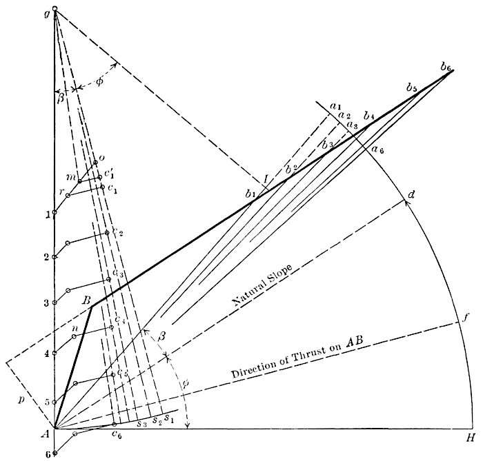
Fig. 11.
Suppose to be the plane of rupture, and call the weight of the prism of rupture, , for a thickness of one unit, . The weight of the prism causes the tendency to slide along the planes, and . This tendency is resisted by the reactions of the wall, , and the plane, . The reaction of the wall consists of the normal component, , acting to the right, and the friction resistance, , acting up. The resultant of these two forces, , which is equal and opposed to the earth thrust on , thus makes the angle, , with the normal to the wall. Its direction is given by in Fig. 11. The reaction of is made up of the cohesion, , acting up along , the normal component, , acting up, and the friction, , acting up along . The two forces, and when combined, give a resultant, , making an angle with the normal, , to . Hence, if the angle, , then gives the direction of the resultant, .
The prism, , is thus in equilibrium under its own weight, , the cohesive force, , acting up along , the reaction, , of , acting to the right, and the force, , acting up. On drawing, to the scale of force, vertical and equal to ; then parallel to and equal to ; then parallel to to the intersection with , the sides of the closed polygon, , in order, will represent the four forces, , , , and , in equilibrium.
A similar investigation pertains to any other supposed prism of rupture. To find the true one, a number of trial planes of rupture, , , ..., are assumed, and each is treated in turn as a true one (though there can be only one true one). As seen above, the resultant of the normal reaction and friction on any trial plane of rupture must be inclined below the normal to the plane at the angle, . To lay off the directions of these resultants, from any convenient point, , say, in the vertical through , as a center, describe an arc, , with a convenient radius, . With the same radius and as a center, describe the arc, , cutting the trial planes (produced if necessary) at , , ..., . Let be the point where the line of natural slope from cuts the arc, . On laying off the chords, , , ..., equal to the chords, , , ..., respectively, it will follow that , , ..., will make angles, , below the normals to the planes, , , ..., respectively. To prove this, take any trial plane, as , which makes the angle, , with , and drop a perpendicular, , from on (produced if necessary); then, because the sides of the angles are perpendicular, , and if , it follows that , as was to be proved. Hence the chord, the chord, , , etc., as stated.
The weights, in pounds, of the prisms, , , ..., are, , , ..., respectively, where is the length of the perpendicular from upon (produced if necessary), the foot being the unit of length and being the weight, in pounds, of 1 cu. ft. of earth. The prisms are supposed to be 1 ft. in length perpendicular to the plane of the paper.
These weights are now laid off to the scale of force, vertically downward from , to points 1, 2, 3, ..., and from these points, lines are drawn parallel to , , , ..., respectively, of lengths equal to , , ..., to represent the forces of cohesion, acting upward along , , ..., where the force of cohesion, in pounds per square foot. From the extremities of these lines, lines are drawn parallel to the direction of the earth thrust on (inclined at the angle, , below the normal to ), to the intersections, , , , ..., with , , , ..., respectively. With dividers, it is found, for this figure, that is the longest of these lines; whence , to the scale of force, measures the earth thrust against , in pounds. This follows, because, for any less thrust, since is fixed, when becomes less, falls to the left of the first position, and the new , representing the thrust on , due to the normal reaction on it and friction only, will make a greater angle than to the normal to , which is inconsistent with the laws of stability of a granular mass. In fact, if is the normal component of the thrust on the plane, , is all the friction that can be exerted on it. The resultant of and thus makes an angle, , with , and this angle cannot be exceeded. The true thrust on the wall, , is thus the greatest of the trial thrusts, . The prism of rupture, , is in equilibrium under the four forces represented by the sides of the closed polygon, ; , representing its weight; , the cohesion acting along ; , the reaction of (opposed and equal to the earth thrust); and the reaction of the plane, , due to the normal component and friction on it only. The full reaction of the plane can be found by combining the forces, given in magnitude and direction by and , but it is not needed.
It is to be noted that is the least thrust for which equilibrium is possible. The other trial thrusts should now be lengthened to equal , since this is the true thrust or reaction of the wall, . All the new points, , , , , , will now lie to the right of the old points; hence the new , , , , , will all make less angles than with the normals to the planes, , etc.; hence stability everywhere in the earth mass is assured.
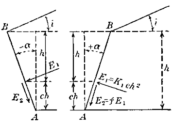
Fig. 12.
The resultant, , of and , evidently makes the angle, , with the normal to , The moment of this resultant about , if we put . From the last formula, it is seen that is the moment of the thrust about , for ; also from , it follows that is the normal component of the thrust for .
When cohesion is included, is not exactly , but it is very slightly less for or 2. It will be assumed at , and, from the values of given by Leygue, will be derived from the formula above,
Thus, for the case represented by Fig. 11, , therefore , ; . Experiment gave , therefore .
Neglecting cohesion, theory gives , or twice the amount given by experiment. If, however, the construction of Fig. 11 is made for the actual height of the retaining board, ft., , (cohesion, in pounds per square foot), we find . On substituting this in the formula, , we have,
By a comparison of the values, it is evident that, if the cohesion was assumed at a little less than 1 lb. per sq. ft., the theoretical and experimental values could be made to agree exactly. The case just examined exhibits the most pronounced difference between the ordinary theory (corresponding to ) and experiment, of any shown in Table 3. Further, it will be observed, that, for an assumed cohesion of about 1 lb. per sq. ft., the theoretical and experimental values for all the cases given by Leygue very nearly agree.
The value, , in place of Leygue’s, , was used, which would alter the results somewhat, but not the general conclusions. The construction of Fig. 11 will give and its normal component, , with practical accuracy, but it is not readily adaptable in finding the plane of rupture. In most of the drawings a small scale was used, in order to limit the drawing to a sheet of writing paper, hence, on both accounts, cannot be counted on to nearer than 1° or 2°, except for , when was found by computation, or by the construction of Fig. 1.
TABLE 3.
..Cohesion, , in pounds per square foot.Angle of rupture with the horizontal, .Coefficient of the normal component of the thrust .
Theory.Experiment.Theory.Experiment.
+⅓0050° 12′0.060
151°51° 30′0.0420.043
252° 30′0.026
+⅓⅔033° 41′0.182
144°47°0.0840.091
249°0.043
00056° 36′0.111
157°56° 30′0.0930.090
258°0.077
358° 30′0.062
0½047° 30′0.178
150°51°0.1480.141
253°0.121
355°0.098
0⅔033° 41′0.345
144°49°0.2050.195
246° 30′0.150
350°0.111
–⅓0060° 21′0.185
163°61°0.1710.179
263°0.155
–⅓⅔033° 41′0.660
157°57°0.2670.387
250°0.236
The results in Table 3 are remarkable, and explain quite satisfactorily how Leygue, Darwin, and others found, by experiments on small models, results differing so much from the ordinary theory, where cohesion is neglected.
It should be remarked that the values of given in Table 3 under “Experiment,” are not exactly those given by Leygue in his tables, but are the averages obtained from the two sets of drawings given by him in the plates, and represent the inclinations of the chords of the really curved surfaces of rupture. His experiments with the spring apparatus are not considered, as the results are open to doubt, because the prism of rupture, in descending, could not slide down freely, but as it advanced would rub over the floor, thus lessening the thrust there considerably.
From Table 3, the results given by experiment are seen to differ widely from the ordinary theory in which .
The discrepancies are largely, or almost entirely, due to the very small models used, as will be evident from the following considerations: Suppose the height, , of the wall, , to be 10 times the height given in Fig. 11, or 6.56 ft.; then, as the areas of triangles such as , etc., vary as the squares of the heights, but the lengths of sides, as etc., vary only as the first power of the heights, the weights of the successive trial prisms of rupture will be or 100 times as great as before, whereas the corresponding cohesive forces, acting along the planes, , etc., will be only 10 times the first values. Hence, if we use a scale of force of the former scale, the weights of the prisms, , , etc., will be represented, as before, by , , etc., but the lines representing the cohesive forces will be only of the former lengths. Thus the new , Fig. 11, will be laid off from 4 only of the length shown in the figure.
The relative decrease in the lines representing cohesive forces will be still more marked for a wall ft. high, the weights of prisms being 400 times as great, but the cohesive forces only 20 times as great as before. It is evident from this reasoning that, for , the cohesive forces are practically negligible for walls, say, 10 ft. high, especially if the earth surface is level. In fact, a little examination of the original drawings showed, for walls about 6 ft. high, that the earth thrust, neglecting cohesion, was only from 1 to 5% in excess over that for . The smaller percentages referring to , or , while the larger percentages referred to , for earth surface horizontal or sloping at the angle of repose.
Such results should be of great service to future experimenters as proving two things: (1) that dry sand, with as small a coefficient of cohesion as possible, should be used (perhaps grain would be a more suitable material), and (2) that no experimental wall should be less than from 6 to 10 ft. high.
Even if the wall is, say, 6 ft. high, if damp clayey earth is used as the filling, with a coefficient of adhesion, , then all the diagrams of forces, as in Fig. 11, will be the same as before, or similar figures, and the discrepancies noted in Table 3, will be as pronounced as ever. All the experiments on retaining boards, except some of Curie’s, have been with very small models, and the results have brought the common theory under suspicion, if not into disrepute.
The writer hopes that the foregoing investigation and results may be instrumental in establishing more confidence in the theory, and in showing when cohesive forces may be practically neglected and when they must be included.
As an illustration, the results for a vertical wall 10 ft. high are presented in Table 4, taking and . In the first wall, the surface of the earth was horizontal; in the second wall its slope was 1 rise to 2 base.
TABLE 4.
.....
00056°36′0.111
156°0.110
557°0.101
1057°0.096
1½047°30′0.178
149°0.176
549°0.165
1049°0.155
In Table 4 the results for and are practically the same, but for is 13% less than for . If the value, , for fresh earth slightly damp and lightly rammed, given by Leygue above, is even approximately correct, it is seen that, for such a filling, the effect of cohesion must be included to get results at all agreeable with experience or experiment.
Recurring to the experimental retaining walls proper, Figs. 4 to 9, it is evident from the foregoing, that cohesion will affect the results inappreciably, except perhaps in the case of Figs. 6 and 7, where the height was about 0.6 ft. Assuming , it seems to be probable, from the results of Table 4, that the thrust should be decreased in the ratio of 93:111. Effecting the construction for the new thrust, it is found that the point, I, falls within the base, 0.03 of its width for Fig. 6 (Trautwine’s wall), and 0.02 of its width for Fig. 7 (Curie’s wall).
The theory advocated is thus practically sustained by all the experiments given above, either on retaining boards or retaining walls proper, when a coefficient of cohesion of about for dry sand is used.
The method of evaluating the thrust, given in Fig. 11, is as valid when , or cohesion is neglected, as in the ordinary theory. The lines parallel to the thrust are now drawn directly from 1, 2, ..., to the intersection with , , ..., and the greatest one is taken for the true thrust. Although the writer expressly disclaims any great accuracy in the values of in Table 4, on account of the small scale of the drawings, nevertheless, the results by the construction for and or ½, were found to differ from computed values only 2, 3, 0, and 1% for the different cases, which should give confidence in the general conclusions, at least.
The diagram, Fig. 11, with a slight modification, can be utilized to find the coefficient of cohesion, , at which the bank of earth will stand without a retaining board. Thus, let each line, as , representing the cohesive force acting along its proper plane, be extended to meet the corresponding ; any such line measured to the scale of force and then divided by the length of the plane along which it acts, will give the cohesive force, in pounds per square foot, corresponding to no thrust on , for the particular plane considered. The greatest of these values is evidently the value of for which the filling will stand without a retaining board. The work can be much abbreviated by using a well-known principle, that the plane along which the unit cohesion is greatest (the plane of rupture) bisects the angle, , between the surface, , and the line of natural slope. Suppose to be this plane, then we have only to extend to meet , at 0, measure 10 to the scale of force, and divide by the length of , to the scale of distance, to find the coefficient desired. By either method it was found that a cohesive force of 7 lb. per sq. ft. was required to sustain a mass of earth with a vertical face, ft. high, when was horizontal.
It was stated, in connection with Equations (1) and (2), referring to the thrust on a vertical wall of height, , with the earth surface sloping at the angle of repose, that this particular case would be discussed later. To show the influence of cohesion, the planes of rupture for such a wall, 2.4 ft. high, for various values of (in pounds per square foot), are given in Fig. 13. The values of (for and ) are as follows:
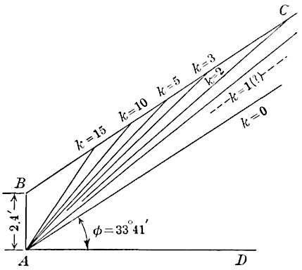
Fig. 13.
The first value was found by computation, the others by construction. As is well known, the theoretical plane of rupture approaches indefinitely the natural slope as approaches zero. For appreciable cohesion (and there is always some cohesion) the plane of rupture lies above the natural slope, with very materially decreasing normal components to the thrust as increases. As the height of wall increases, the influence of cohesion diminishes. Thus, as shown above, for a wall 5 times 2.4 ft., or 12 ft. high, the weights of the prisms, , etc., are 25 times the former values, but the cohesive forces, which vary directly as , etc., are only 5 times the first values. Hence, if the former values of are multiplied by 5, the new diagram of forces, Fig. 11, will be similar to the old one. Thus, for the wall 12 ft. high, the plane of rupture and the value of , for , correspond to the old values for , for , to the old values for . For fresh earth filling, slightly packed, it is possible that the values, , , may be reached, with a material reduction in from the values given by Equations (1) and (2). As the height of the wall increases, say to 25 or 50 ft., the influence of cohesion, in diminishing the thrust, becomes very small, and it is better to ignore it altogether. In fact, as we know very little, and that imperfectly, of the coefficients of cohesion, it is perhaps safer, at present, to use Equations (1) and (2) in all cases. It is very evident, though, that for most cases in practice, the formulas give a very appreciable excess over the true thrust, and that the true plane of rupture never coincides with the natural slope.
From all that precedes, it is seen that the results of experiments on small models in the past have proved to be very misleading, and that experiments on large models are desirable, and can alone give confidence. Leygue has made such experiments on retaining boards, from 1 to 2 m. (3.28 to 6.56 ft.) in height, simply to determine the surface of rupture. This is really the essential thing, for, as soon as the prism of rupture is known, the thrust is easily found. In a general way, the results agree with theory when the cohesion is neglected, though the curved surfaces of rupture were very irregular, particularly for the stone filling. The first two experiments were made with both dry and damp sand as a filling; the next six, with stones varying from 1.5 to 20 in. in diameter. In another series of five experiments, sand was used. In all the foregoing experiments, the surface of the material was horizontal. In three additional experiments, the walls were surcharged with sand as a filling. In one experiment, the wall was 6.56 ft. high and the surcharge was 3.28 ft.; in another experiment, the wall was 3.28 ft. high, and the sand, sloping from its top at the angle of repose, as in the former case, extended to 3.28 ft. above the wall, where the surface was horizontal.
Applying the construction of Fig. 1, it was found that the plane of rupture passed, say, 2° above that given by experiment in the first case and about 3° below in the second. It will be evident from the construction of Fig. 11, omitting cohesion, that trial planes of rupture differing by 2 or 3° from the true one, give nearly the same thrust. Taking the average, these experiments on large models, tend, in a general way, to sustain the theory.
At the moment of failure, the wall was 12 ft. 10 in. high, the thickness of the panel was 18 in., and the counterforts were 10 ft. from center to center, projecting 27 in. from the wall, or 3 ft. 9 in. from the face, as inferred from the next example. As it is stated that the wall had the same volume as the 10-ft. wall previously examined in this paper (Fig. 4), the counterforts must have been 2 ft. thick. Assuming these dimensions, and using the values given; , or (say ), weight of a cubic foot of earth, and weight of a cubic foot of masonry, we first compute lb., the normal component of the earth thrust on a length of 1 ft. of wall. The normal thrust on the panel is thus and on the counterfort . The friction (acting vertically downward) caused by this thrust is on the panel and on the counterfort. The moment of these forces about the outer toe of the wall, totals 39 800 ft‑lb. The resisting moment of 10 ft. in length of combined panel and counterfort, about the outer toe, assuming the wall to be vertical, is 29 800 ft‑lb. If, to the latter, we add the moment of 17% of the weight of earth between the counterforts, supposed to be held up by the sides of the latter, the total moment exactly equals the first. However, at the moment of failure by overturning, the panels had bulged 4½ in. and the overhang at the top was 7½ in. Taking the moment of stability of the wall at 26 000 ft‑lb. (Mr. Baker’s figure), it is found that, for equilibrium, 24% of the weight of earth between the counterforts must be carried by them, When the earth was 8 ft. high, a heavy rain was recorded, so that, doubtless, some appreciable cohesion was exerted, though necessarily omitted in the computation.
The experimental wall of Col. Michon was 40 ft. high, with very deep counterforts, only 5 ft. from center to center. The very heavy and wet filling between the counterforts, being treated as a part of the wall, a construction (made on the printed drawing) shows that the resultant of earth thrust and weight of wall passes through the outer toe. Doubtless the cohesion factor in this wall was large. In the paper mentioned, the details as to Gen. Burgoyne’s experimental walls are given. There were four of these walls, each 20 ft. long, 20 ft. high, and with a mean thickness of 3 ft. 4 in. Two of the walls were perfectly stable, as in fact theory indicates for all four walls if they were monolithic. The other two walls fell, one bursting out at 5 ft. 6 in. from the base, and the other (a vertical wall), breaking across, as it were, at about one-fourth of its height. As these walls consisted of rough granite blocks laid dry, it is highly probable that the breaks were due to sliding, owing to the imperfect construction; besides, “the filling was of loose earth filled in at random without ramming or other precautions during a very wet winter.”
From a consideration of all the observations and experiments (some of them unintentional), Mr. Baker concludes that the theoretical thrust is often double the actual lateral pressure. He used the old theory, which neglects both cohesion and wall friction. If he had included them, the resulting theory would not have been so deficient “in the most vital elements existent in fact” as he charges against the “textbook” theory.
However, the writer must be clearly understood as not recommending that cohesive forces be considered in designing a retaining wall backed by a granular material, such as fresh earth, sand, gravel, or ballast. It has been the main object of this paper to show that, although cohesive forces must be included in interpreting properly the results on small models and many retaining walls, yet, for walls more than 6 or 10 ft. in height, backed with dry fresh material, not consolidated, the cohesive forces can be practically neglected in design. Hence, experimenters are strongly advised to leave small models severely alone and confine their experiments to walls from 6 to 10 ft. high, backed by a truly granular material, such as dry sand, coal, grain, gravel, or ballast, where the cohesive forces will not affect the results materially. Further, it is evident that walls of brick in wet sand, or walls of granite blocks, etc., laid dry, are very imperfect walls. The overhang, just before falling, is large, and the base is often imperfect. For precise measurements, a light but strong timber wall on a firm foundation, seems to be best; and the triangular frame of Fig. 8 seems to meet the required conditions very well, especially if the framing is an open one, with a retaining board only on one leg. The base thus becomes wider, and the overhang less, than with any rectangular wall.
When the design of a wall to sustain the pressure of consolidated earth is in question, even if a perfect mathematical theory existed, it would still prove of little or no practical value, because the coefficients of friction and cohesion are unknown. The coefficient of friction at the surface can be easily found, but it is a difficult matter to find the coefficient of cohesion, which doubtless varies greatly throughout the mass.
Mr. W. Airy, in his discussion of Mr. Baker’s paper, states that he found the tensile strength of a block of ordinary brick clay to be 168 and of a certain shaley clay 800 lb. per sq. ft., the coefficients of friction for the two materials being 1.15 and 0.36, respectively. Cohesive resistance is more analogous to shear, but such figures indicate the wide variations to be expected, particularly in , the coefficient of cohesion. If this coefficient is to be guessed at, in order to substitute it in the supposed perfect formula, then it is plainly better to guess at the thickness of the wall in the first instance.
which gives the height, , of vertical trench that will stand without any sheeting.
In this equation,
Thus, if , whence , the equation reduces to
As certain trenches with vertical sides have been observed to stand unsupported for heights of 15 or even 25 ft., the equation would seem to indicate that cohesive or shearing resistances of about 200 to 300 lb. per sq. ft. were required to cause equilibrium. If friction is not supposed to be exerted, then and ; and, for the same unsupported heights, the cohesion would be about doubled. Evidently, if cohesion, which (to judge from Mr. Airy’s experiments) may vary from one to several hundred pounds per square foot, has to be guessed at in order to determine , it is plainly better to guess at at once.
The foregoing equation cannot be regarded as giving very accurate results, mainly because a plane surface of rupture is assumed, whereas, from both theory and observation, this surface is known to be very much curved; besides, the cohesion and friction along the ends of the break have been neglected. However, the hypothesis of a plane surface of rupture, the ends being supposed to be included, gives a greater value to than the true one, whereas, neglecting the influence of the ends, it tends in the other direction; so that the equation may not err so greatly.
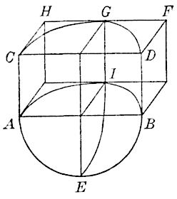
Fig. 14.
This is possible; but, if so, as the sheeting is not supposed to be carried to the bottom of the trench, there can be no vertical component in its reaction, and the thrust, , of the braces and sheeting, acting on , must be horizontal; further, the earth cannot act as a series of independent arches devoid of frictional resistance between them, but must act as a whole.
Another way of explaining the phenomena is to suppose the horizontal thrust of the braces, , on the exposed face, , to cause friction at the back of the break of sufficient intensity to prevent the semi-cylinder from descending, just as a book can be held against a vertical wall by a horizontal push.
To illustrate the principle, it will suffice to replace the semi-cylinder by the circumscribing parallelopiped, , and suppose it to be held up by the friction on the back face, with possibly cohesion acting on the three interior vertical faces. Thus, let , and ; then the friction on the back face is , the cohesion on the three faces is , and the weight of earth, , equals . Hence, as friction and cohesion always act opposite to the incipient motion, or vertically upward in this case,
Evidently, the value of , derived from this equation, gives an extreme upper limit, which is doubtless never attained, as there is nearly always some support from the earth which has not broken out below the level of .
Where the sheeting and bracing are of sufficient size, are tightly keyed up, and extend to the bottom of the trench, or where the bank is supported by a retaining wall, the earth near the bottom cannot break out, and the equation is not valid.
However, if, from any cause, such as insufficient sheeting, the break has taken place over even a part of , the mass, , above will tend to tip over at the top, giving the greatest pressure on the top braces. This appears to explain the phenomena observed by Mr. Meem and others in connection with some trenches.
With regard to tunnel linings, as is well known, the vertical pressure on the top is generally small, the great mass of earth vertically over the tunnel being largely held up by the friction of the earth (caused by the earth thrust) on its vertical sides, exactly as in the case of tall bins, where most of the weight of the grain is held up by the sides of the bin, the theory being very similar in the two cases. In consolidated earth, cohesion assists very materially in this action.
It might be inferred, from the facts of observation, that consolidated earth acts as a solid, though, of course, it differs from a solid in this: that its physical constants (cohesion, friction, etc.) vary enormously with the degree of moisture. It is likely that these constants alter with the depth, and likewise are subject to changes from shocks.
From the present state of our knowledge with respect to the theory and physical constants pertaining to consolidated earth, it would seem that experience must largely be the guide in dealing with it. The facts are supreme—the rational theory may come later.
Similarly, for retaining walls backed by loosely aggregated, granular materials, the facts are supreme, and, on that account, they have been presented very fully in this paper; further, a theory has been found to interpret them properly. It is true that the fresh earth, from the time that it is deposited behind a retaining wall, begins to change to a consolidated earth, from the action of rains, the compression due to gravity, and the influence of those cohesive and chemical affinities which manufacture solid earths and clays out of loosely aggregated materials, and even cause the backing sometimes to shrink away from the wall intended to support it; but it is plain that the wall should be designed for the greatest thrust that can come on it at any time, and this, in the great majority of cases, will occur when the earth has been recently deposited.
The cases which have been observed where the bank has shrunk away from the wall and afterward ruptured (after saturation, perhaps) are too few in number to warrant including in a general scheme of design, even supposing that a rational theory existed for such cases. A few remarks on the theory pertaining to the design of retaining walls may not be inappropriate. From the discussion of all the experiments referred to in this paper, the conclusion may be fairly drawn that the sliding wedge theory, involving wall friction, is a practical one for granular materials of any kind subjected to a static load. In practical design, however, vibration due to a moving load has to be allowed for; also the effect of heavy rains. Both these influences tend generally to lower the coefficients of friction and add to the weight of the filling. Mr. Baker says:
Instances of slips in railway cuttings, caused by the vibration set up by passing trains, have been given by many engineers. The effect of vibration is most pronounced near the top of a retaining wall, and is evidently greater for a low wall than for a high one. All the influences cited can only be included under the factor of safety, and the writer recommends for walls from 10 to 20 ft. in height a factor of 3. This may be increased to 3.5 for walls 6 ft. high and decreased to 2.5 for walls 50 ft. high, or those with very high surcharges. In the application, the normal component of the earth thrust on the wall, , will alone be multiplied by the factor, the friction, , exerted downward along the back of the wall, being unchanged. This allows very materially for a decrease in due to rains and vibration, as well as for an increase in the thrust, due to becoming less.
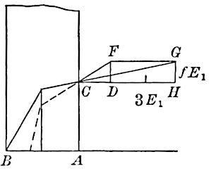
Fig. 15.
The effect is illustrated in Fig. 15, where a retaining wall is supposed to be subjected to the earth thrust, , making an angle with the normal to the face, , of the wall. The component of normal to is , the component acting downward along is represented in magnitude and direction by , which equals . Suppose the factor of safety to be 3, then is extended to , making ; is drawn equal and parallel to ; whence will represent the thrust, which, combined with the weight of the wall, acting through its center of gravity, must pass through the outer toe of the wall.
To see what thickness of a vertical rectangular wall corresponds to this factor of safety, 3, for , or a natural slope of 3 base to 2 rise, let it be assumed that the weights per cubic foot of earth and cut-stone masonry in mortar are in the ratio of 2:3; then, for level-topped earth, a computation shows that, for the factor, 3, the base of the wall must be . If the earth slopes indefinitely at the angle of repose from the top of the back of the wall, and a factor 2.5 is used, then the thickness will be .
For brick masonry in mortar, the specific weight of which is of that of the filling, the foregoing thickness would be changed to and , respectively, being equal to the height of the wall.
It must be noted especially, however, that if the original earth thrust, when combined as usual with the weight of wall, gives a resultant which passes outside of the middle third of the base of the wall as computed above, then the thickness must be increased, so that the resultant will at least pass through the outer middle-third limit. This ensures compression over the whole base and no opening of part of the joint under normal conditions. With regard to the thickness above of about one-third of the height, Mr. Baker states that hundreds of brick revetments have been built by the Royal Engineer officers, with a thickness of only for a vertical wall. He advises, as the result of his own extensive experience, that the thickness be made one-third of the height for level-topped earth of average character, and that the wall be battered 1½ in. to the foot. He states, further, that, under no ordinary conditions of surcharge on heavy backing is it necessary to make the thickness of a retaining wall on a solid foundation more than one-half the height. The thicknesses computed above agree fairly well with those recommended by Mr. Baker, and it would seem that a table of thicknesses computed on the above basis should correspond to safe walls under ordinary conditions.
It has been noted above that Equation (1), corresponding to a slope of indefinite extent, probably gives too great a thrust; besides, there are no embankments with such a slope. An embankment from 100 to 150 ft. high, supported by a low wall, may approximate the conditions assumed, but, before it is finished, the earth has consolidated to such an extent that the actual thrust is doubtless much less than the computed one. The truth is that, in nearly all back-filling of ordinary earth, the cohesive and chemical affinities commence their work very soon after the filling is deposited, and consolidation is gradually effected; so that, as has been stated, the actual thrust is often much less than is estimated in the design of the wall, where cohesive forces are neglected. In many old walls, as has been observed, the consolidation has gone so far that the backing has shrunk away from the wall altogether. It would be hazardous, though, to allow for cohesion, in a wall backed by fresh earth, unless the surcharge was high and was a long time in building. Finally, it should be observed that the footing of a retaining wall should be wide, and should always be tilted at such an angle that sliding is impossible.
A glance at Figs. 4, 5, and 6, will make it apparent that the Rankine and other theories differ in their results mainly because of the assumed difference of inclination of the earth thrust. In the design of walls, however, the method proposed (Fig. 15) will approximate in results those given by the Rankine theory, where, say, the earth thrust, whether inclined or not, is multiplied by the factor of safety. The writer does not advocate the middle-third limit method in design, as it gives variable factors of safety for different types of walls. Besides, if the actual resultant on the base passes one-third of its width from the outer toe, there is no pressure at the inner toe, and the unit pressure at the outer toe is double the average. If vibration or other cause increases the thrust, the joint at the inner toe opens, and the pressure is concentrated too much near the outer toe. In the reinforced concrete wall, the earth thrust on a vertical plane through the inner toe is required. As this plane lies well within the earth mass, the thrust on it must be taken as acting parallel to the top slope, and its amount will be the same as that given by the Rankine theory.
Although it is highly desirable to have more precise experiments on large models in order to draw sure conclusions, yet, as far as the experiments go—those which have been analyzed and discussed in this paper—the following conclusions may be stated:
1.—When wall friction and cohesion are included, the sliding-wedge theory is a reliable one, when the filling is a loosely aggregated granular material, for any height of wall.
2.—For experimental walls, from 6 to 10 ft. high, and greater, backed by sand or any granular material possessing little cohesion, the influence of cohesion can be neglected in the analysis. Hence, further experiments should be made only on walls at least 6 ft., and preferably 10 ft., high.
3.—The many experiments that have been made on retaining boards less than 1 ft. high, have been analyzed by their authors on the supposition that cohesion could be neglected. This hypothesis is so far from the truth that the deductions are very misleading.
4.—As it is difficult to ascertain accurately the coefficient of cohesion, and as it varies with the amount of moisture in the material, small models should be discarded altogether in future experiments, and attention should be confined to large ones. Such walls should be made as light, and with as wide a base, as possible. A triangular frame of wood on an unyielding foundation seems to meet the conditions for precise measurements.
5.—The sliding-wedge theory, omitting cohesion but including wall friction, is a good practical one for the design of retaining walls backed by fresh earth, when a proper factor of safety is used.
As the subject of pressures on the roof and sides of a tunnel lining has received much attention of late, the writer has concluded to extend this paper, so as to give a development of a theory, based on the grain-bin theory of Janssen, but modified to include the cohesive or shearing resistances of the earth in addition to the frictional resistances.
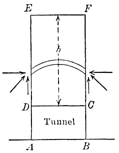
Fig. 16.
Fig. 16 is a vertical transverse section of a tunnel, , and the earth, , extending over it feet. If this tunnel has been driven by the use of a shield or poling boards, the ground will tend to settle over it, and part of the weight of will be sustained by cohesion and friction (resulting from the lateral thrust) exerted along the sides, vertically upward. The earth will probably arch itself, or form a series of domes superposed one upon the other, but the external forces acting on such domes will be the same as those acting on a corresponding horizontal lamina, and the theory, given in full in the Appendix, begins with the considerations pertaining to the equilibrium of such a lamina.
If there was no settlement of the earth, , in relation to , then the vertical pressure per square foot on would be ( being the weight of a cubic foot of the earth in pounds), but, as most of the weight of is carried by the sides, in case of sufficient settlement, the vertical unit pressure, , on , will be much less than . Also, the lateral unit pressure, , at the level, , will be much less where settlement occurs. From the equations for and , given in the Appendix, the diagrams, Figs. 17 and 18, have been constructed.
In both diagrams, the weight of the earth was taken at lb. per cu. ft., and the cohesion of the earth at lb. per sq. ft. In Fig. 17, and the curves for and were laid off for a width of tunnel, , of 15 ft. and also for 30 ft. In Fig. 18, , and curves are given for and , also for ft. and 30 ft. for various heights, .
It will be perceived, in both figures, that when certain heights are attained, both and cease to increase perceptibly, so that such values may be taken as corresponding to indefinitely large.
Fig. 17. Fig. 18.
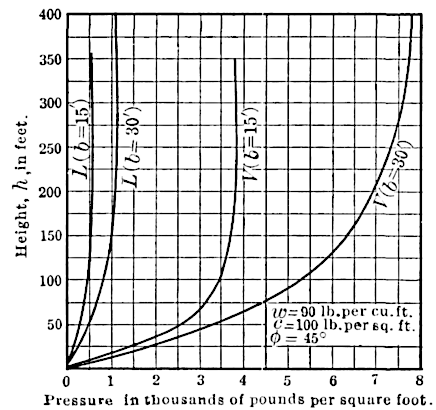
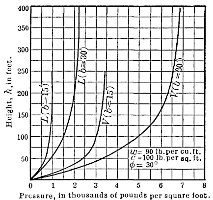
The value of , in Figs. 17 and 18, is the average vertical unit pressure at the top of the tunnel. Experiments on grain bins lead to the inference that the pressure at the middle of the roof is greater than that at the sides, but no law of variation can be stated.
The lateral unit pressure on the vertical sides of the tunnel lining at the top is given by the equation for , or by the corresponding diagram. The variation in this lateral pressure over the sides of the tunnel cannot be easily formulated, as so much of the weight of the earth, directly over the tunnel, has been transferred by a kind of arch action to the sides. Experience would better speak here.
Table 5 gives the values of and for ft. The figures in Columns are taken from Mr. Meem’s table, previously referred to; those for Columns are from the diagrams, Figs. 17 and 18.
In quoting Mr. Meem’s figures, the writer must not be understood as endorsing in any way his theory; but the results are of interest as embodying the conclusions of a practical engineer of large experience.
TABLE 5.
, in feet.., in pounds per square foot., in pounds per square foot.
....
1545°1 4852 300405300
1530°1 0352 100540600
3045°3 2402 800450400
3030°2 3252 600450750
If the height, , of earth covering is 200 or 300 ft., the values given by Figs. 17 and 18 are much larger than those given in Columns , which presumably represent Mr. Meem’s pressures for any height greater than 40 ft.
In saturated earth, it has been customary, perhaps, to regard the earth as if it were gravel composed of solid spheres, like marbles, so that the water has free access in any direction. Thus, in the case of a retaining wall backed by such material, the water has full access practically to every part of the wall, and the wall is subjected to the full water pressure corresponding to its depth. It is likewise subjected to a thrust from the earth, corresponding to and , for the saturated material, but with a weight per cubic foot equal to that of the earth in air less the buoyant effect of the water. Thus, if a cubic foot of the porous earth, in air weighed 90 lb., and if the voids were 40%, then 1 cu. ft. of earth contains 0.6 cu. ft. of solids and the buoyant effect of the water is the weight of an equal volume of water or lb. Hence, the weight per cubic foot of earth in water is lb.
Similarly, for the pressures, and , at the top of a tunnel, must be replaced by 52.5, and and must be found for the saturated material and these values substituted in Equations (5) and (6) of the Appendix. To these pressures must be added the corresponding water pressures for the full height of water, supposing it to have free communication everywhere, as in the case of the gravel filling. However, with sand, or earth with much fine material, the pores are more or less clogged up and there is perhaps intimate contact of a part of the earth with the roof of the tunnel, so that the water cannot get under it to produce a lifting effect, and if such intimate contact is found along any horizontal or vertical section, of the earth on either side of the section, it is plain that the buoyant effort of the water on a cubic foot of material will be much diminished.
This value replaces the in Equations (5) and (6) from which the and for the top of the tunnel are found. To these values, add , for the water pressure, where the surface of the water extends a height, , above the top of the tunnel. Similarly, in the case of the retaining wall, add 0.4 of the full water thrust on the wall to that given by the earth, weighing only 75 lb. per cu. ft.
As a numerical illustration, take ft., , in air lb., ft., ft.; but we must now replace by the weight in water, 75 lb., as found above. The values of and are now found, by Equations (5) and (6) (Appendix), to be 1 917 and 246 lb. per sq. ft., respectively, for the saturated earth alone. To these values add lb. per sq. ft., water pressure, giving a total of 3 417 and 1 746 lb. per sq. ft., respectively, for the vertical and horizontal unit pressures at the top of the tunnel lining.
In connection with this subject of underground pressures, it may not be inappropriate to make some concluding remarks on the maximum vertical pressures to which culverts may be subjected.
Let Fig. 16 now represent a longitudinal vertical section along the axis of a road embankment, built over an arch culvert or box-drain, , the line, , passing through the summit of the arch or the top of the covering stone of the box-drain, and the lines, and , coinciding in part with the exterior sides of the abutments.
There is a horizontal thrust of the earth on the medial plane, , acting at right angles to the plane of the paper, which tends to distribute the weight of the central portion partly toward the sides; but, ignoring this, it is seen that, if the earth everywhere settles uniformly, the maximum pressure per square unit at the top of the culvert is , and the total vertical pressure on the culvert is the weight of the earth vertically above it.
If, however, the earth outside the abutment walls settles more than the walls (a case which may occur), then part of its weight, and that of the earth vertically above it, will be transferred, through friction and cohesion, along the planes, and , to the culvert, and thus the vertical pressure on the top of the culvert will be greater than in the first supposed case; but, if the reverse obtains, or if the culvert settles more than the earth outside the lines, and , or if the arch or covering stone descends in the middle relatively to the abutments, then part of the weight of the earth vertically over the culvert is transferred to the sides. For a comparatively rigid arch, the settlement is perhaps not enough to warrant us in making the maximum unit pressure less than . Exactly what settlement would warrant the use of the theory set forth in the Appendix it is impossible to say. If the unit pressure is taken as , we can rest assured that in most cases the real pressure is materially less.