DISCUSSION.
Reading edition
DISCUSSION.
J. R. Worcester, M. Am. Soc. C. E. (by letter).— In reading Professor Cain’s admirable paper relating to experiments on retaining walls, the writer has looked in vain for a word of caution as to the effect which time plays in modifying the condition of equilibrium within a mass of earth. The author evidently considers it necessary to allow (by using a factor of safety) for a possible lessening of the angle of friction on account of a change in the amount of moisture, and possible vibrations, but states that in a great majority of cases the greatest thrust will occur where the earth has been recently deposited. It would appear that he neglects a possibility, if not a probability, of a readjustment of the earth particles through the influence of time, by which the angle of friction is lessened if not wholly cancelled.
The theory that cohesion in the earth and frictional resistance on the back of the retaining wall account for the experimental results seems indisputable, but such experiments must needs be carried through in a reasonable time, and, in that respect, at least, must needs differ from actual constructions which are intended to be permanent.
It is well known that unbraced excavations can often be carried vertically to considerable depths in safety, but that not infrequently— as many have learned to their sorrow— such unbraced banks have subsequently caved in. The slides in the Culebra cut may be mentioned as a similar illustration. To be sure, the delayed motion of the earth (or rock) may be attributed to the effect of moisture, but that does not invalidate the argument, as one always has to reckon with water.
It is also a matter of common knowledge that, in braced excavations, the pressure on the sheeting and bracing frequently increases in time to an extent enormously exceeding the original pressure. In many instances this has caused a failure long delayed.
Another instance of the effect of time is found in many retaining walls, in which a very slow motion has occurred, though the walls appeared to be entirely stable when first built.
A frictional or tangential force along the back of the wall may tend to prevent motion, but it is difficult to conceive of this tangential force being perpetually present on the back of a stationary wall after the back-filling has become settled and consolidated. In the interior of the mass of earth at rest the author admits that the reaction between particles is not along inclined lines, but rather that the lines of pressure are vertical and horizontal. The vertical lines of force are, of course, caused by gravity, and the horizontal lines by the tendency of particles to wedge in between those below and to spread them.
If this conception of the forces within a mass of earth is reasonable, it would seem as if it might also be extended to the pressure against an immovable vertical wall. One must then consider whether it is possible for a horizontal pressure to cause the wall to move, without changing the conditions and introducing the inclined stresses. It would seem within the bounds of possibility that a very minute motion might be produced, and that this would be followed by a readjustment of stresses in the earth by which the forces would gradually resume the horizontal direction.
The nature of the soil undoubtedly has much to do with this question. In some kinds of clay there appears to be a sort of viscosity, such as is frequently seen in pitch and other materials, or a tendency toward a slow flowing. No amount of pressure would cause a sudden motion, but time will effect a motion under a slight pressure or even the force of gravity alone. It appears that this condition is produced by the very minute particles, each moving individually into a position in which the surrounding forces balance. If one cuts a vertical face in such material one cannot force the exposed particles out of their position by crowding them from behind, but each in its turn will feel the pressure unbalanced and will slowly move out. This may not be true to the same extent with granular materials of large diameter, but a familiar instance is seen in fine wet sand. If a small excavation is dug in a wet beach sand, the banks will stand vertically at first, but, by watching closely, one may see the particles, beginning at the foot of the bank where there is most water, gradually moving out, overcoming the force of cohesion, and ever tending to seek a condition with a level surface. It seems quite likely that a similar tendency would exist in almost all soils, to greater or less degree, though perhaps it might be safely neglected in a mass of hard, irregularly-shaped fragments of stone which could interlock.
The point which the writer wishes to make is that a word of caution should accompany this argument for the frictional and cohesive forces; that they cannot always be relied on; and that sometimes the Rankine theory may be better than the wedge theory in designing, even though it does not seem to fit the experimental results.
Another warning may not be amiss, in considering the safe thickness to allow for retaining walls, and that is the effect of frost, where the surface of the ground is level and likely to retain moisture. The swelling force of freezing, under these circumstances, may be more than sufficient to overcome the beneficial effects of both cohesion and friction. Presumably this must be provided for in the “factor of safety,” and is in itself a justification for a very appreciable factor.
It may be well to emphasize the fact that a large part of the author’s assumed factor of safety seems to be absorbed in keeping the resultant within the middle third of the base. The proportions between width of wall and height, determined on pages 433 and 434, are such as to keep this resultant just within the base. If, with these same proportions of wall, the factor were assumed so that the resultant were within the middle third, it would be found to be nearer 1¼ than 3. The author’s statement on page 435, that he “does not advocate the middle-third limit method in design,” is not wholly clear, but the implication is that the resultant should be well within this limit. In this case, it seems as if the factor of safety would be wholly absorbed in thus locating the resultant, and would leave nothing for other elements of uncertainty.
J. C. MEEM, M. Am. Soc. C. E. (by letter).—In the writer’s judgment the author has gone a step forward in developing the relation of cohesion and friction to walls and tunnels, but he has not given sufficient value to the larger consideration of what may be called “cohesive friction” induced by the lateral pressure of earth against retaining walls and other faces. This will be noted later in the discussion.
The writer agrees with the author that the theory of a sliding wedge is the best practical one for retaining walls, and if the face of the wedge be keyed tight, as stated by the author, or through the compacting of the material into a more solid mass, it will be seen that, with no break, the resultant pressures against the wall or face are virtually those, not only of a sliding, but of a solid wedge tending to slide on the plane of repose, the mass being compactly held together by cohesion induced by lateral pressure. Although the general solidity of this mass is dependent on the stability of the wall or bracing, the pressures caused by the tendency of this solid wedge to slide are not affected materially by slight changes in form due to gradual settlement, which, in turn, may be caused by the normal yielding of the wall or shrinkage of the bracing, or by any small losses of material, as long as any of those or their sum is not sufficient to cause partial or final collapse. Assuming then that this theory of the solid wedge tending to slide is the true one, it is difficult to reconcile it with the results of experiments on revolving boards or revolving walls, except in so far as they relate to the more accurate determination of the coefficients of friction and cohesion.
A 2-in. pipe, 18 in. long, was filled with dry sand for a depth of 12 in., and a thin piece of tissue paper was pasted across the bottom. Then, with a wooden piston bearing on the sand, the latter would support the blow of a sledge hammer or the weight of a man without breaking the tissue paper.
All these experiments seem to prove very clearly that pressure is distributed laterally, at least through perfectly dry material, and, with certain values known, it should not be difficult to compute the value of this thrust. For example, if, in the pipe experiment, the exact coefficient of friction of the granular particles against the inside of the pipe is determined to be 0.4, then it would take a pressure equal to the complement of this, or 0.6 of the weight, to hold the granular particles against the vertical side. Now, if the exact depth of sand is determined at which no further pressure (by reason of adding to this depth) is transmitted to the bottom, then, by finding the difference or loss of pressure at the bottom, it should be a simple matter to compute the amount of thrust developing sufficient friction over the given area to sustain the additional weight. This is what the writer, for want of a better term, has called “cohesive friction” induced by lateral pressure. While such experiments on a small scale give definite results with very dry sand or wheat, they will not be conclusive unless made on a very large scale in cases where dampness adds materially to the normal cohesion of small masses.
As to the experiments on revolving boards or walls referred to by the author, it would appear that, as noted, they eliminate consideration of the effect of pressure as increasing the values of the coefficient of friction and cohesion.
The writer believes that it can be shown by Fig. 22 that the lateral pressure against sheeted faces or retaining walls is greater toward the top. Fig. 22 is adapted from Fig. 5 in the writer’s paper, “Pressure, Resistance, and Stability of Earth.”
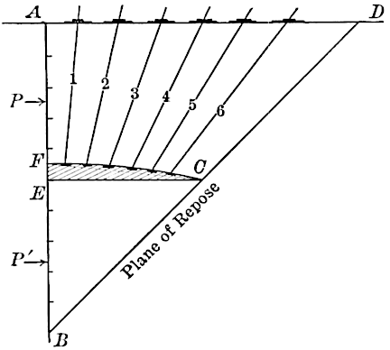
Fig. 22.
It is supposed that a retaining wall has first been built along the face, , and that it has been back-filled with ordinary dry sand to the curved line ; this is then covered with a heavy canvass or tarpaulin, and Rods 1, 2, 3, etc., are run through it in sufficient numbers to hold it in position when the area, , has been back-filled with dry sand. The tarpaulin is then keyed up tight by the rods bearing on washers of large area on the top plane, . If the sand in the area, , be then removed, the observer is asked to note whether, in his judgment, the resulting pressure is greater at or at . It must undoubtedly be true that if this experiment establishes the writer’s claim in the case of normally dry sand, it will tend to do so much more readily in the case of mixed sands and earths as ordinarily found in trenches. If this fact of the greater pressure toward the top be proved conclusively, as the writer believes it undoubtedly will be in time, it may account for some of the failures of retaining walls.
It seems that in order to accord our views to the theory of greater pressure at the bottom, we must assume that any given area of the face of a wall is borne on by a prism of material reaching to the top of the bank, and that its pressure is measured by the weight of its cross-section by some multiple of its length. A few moments spent in examining the face of a tunnel drift, or sheeted trench in sharp sand or loam, will convince any one that this cannot be true. In effect, the face of a sheeted trench resists the pressure of what may be termed a series of vertical groined arches, the braces being at the various abutments and the sheeting supporting the more or less loose material between. In no other way can the fact be explained that individual sheeting planks may frequently be removed for a short time without danger, even when the bracing shows evidence of very heavy pressure; whereas the removal of even a single brace may cause collapse.
A few years ago the writer was called to examine a 44-ft. trench which had collapsed. While it will probably never be known definitely how or where the failure first occurred, it may be of interest to note that within 50 ft. of the break and under conditions apparently similar to those which had existed there previously, the writer found intermediate sheeting planks near the bottom, behind which the pressure was not sufficient to force them out against the rangers, whereas no one could for a moment doubt that there was pressure against the braces or on the sheeting directly behind them. In order, then, that experiments on retaining walls or sheeted faces may be of value, the pressures must be measured against areas absolutely independent of each other; and the writer believes that this can best be done as stated heretofore.
The author states:
“However, if, from any cause, such as insufficient sheeting, the break has taken place over even a part of , the mass, , above will tend to tip over at the top, giving the greatest pressure on the top braces. This appears to explain the phenomena observed by Mr. Meem and others in connection with some trenches.”
The writer thinks it is unfortunate that the author has not had an opportunity of visiting with him many trenches in which no break had occurred, and yet in which the bracing had to be strengthened continually near the top. This was especially true of a horizontally sheeted and braced shaft of large area. The writer believes that it is not out of place to express the hope that the author may still change his viewpoint, and may eventually regard only as phenomena well-braced trenches which in sand or gravel do not show evidences of heavier pressure near the top.
Referring now to tunnel pressures, the author states:
“If there was no settlement of the earth, , in relation to , * * * but, as most of the weight of is carried by the sides, in case of sufficient settlement, the vertical unit pressure, , on , will be much less than .”
The writer would criticize this view because it brings in the element of settlement as essential to its conclusions, and, therefore, is contrary to his belief that all earth is under stable conditions due to the lateral transmission of thrust due to weight, thereby causing the “cohesive friction” previously noted. This transmission of thrust results in what may be termed “arching stability,” which is unchanged when small areas of hard, dry ground are undermined. When normally dry soft ground is disturbed, however, there is a gradual settlement of tiers of strata, and as those above are, in turn, left without support, they settle on what may be termed a new centering and form themselves into new arches. If these strata are composed of sand and gravel, with little natural cohesion, the action of this settlement will be similar to that observed in an hour-glass and will “work” to the surface in a short time. It should be noted, however, that as the voids below are filled and solidified by the pressure, the lateral thrust of this pressure causes the arching tendencies to be resumed again in each successive stratum, relieving the lower strata of the pressure or shock of fall from those above.
The tables given by the author on Figs. 17 and 18, show that the pressure per square foot on the roof of a 15-ft. tunnel at a depth of 150 ft., for instance, is approximately double that on the same tunnel at a 50-ft. depth. This assumption is not justified by any facts which have ever come under the writer’s notice or have been brought to his attention. The observation of any tunneling operations in soft normally dry ground, or the examination of existing structures, will convince any one that, after a depth of approximately twice the greatest diameter of opening has been reached, it is impossible to tell, by any difference in the pressure, the depth of the tunnel. While numberless instances could be cited to illustrate this fact, two which have come under the writer’s notice may be of interest.
In the case of a 15-ft. tunnel passing the bed of an old underground stream, a considerable amount of ground was lost through the influx of sand which came in with the water. For several days after this the writer examined the surface directly overhead for evidences of settlement, and after some 4 or 5 days he found a hole some 12 ft. in diameter and 8 or 10 ft. deep, which was at once filled in. Had the mass of earth of this area and some 20 to 60 ft. high come down on the timbering suddenly, without any intervening “arch cushion,” it would undoubtedly have crushed it; and yet none of the night men had been conscious of even the slightest shock.
In the other case, a heavy rain had caused a large pond to form over the heading of a 15-ft. tunnel, and before it could be drained away it broke through the unprotected face of the heading, virtually filling the whole tunnel with sand for some distance. This, however, had not caused the collapse of any of the bracing, and, before work could be resumed, it was necessary to re-excavate the material. This material was used to fill in the hole caused by the cave-in, and when operations were finally resumed, about 10 days later, the sectional shields, which had remained in position undisturbed, were started with less than the ordinary pressure, as indicated by the gauge on the hydraulic pump.
The writer confidently believes that the assumption behind the reasoning by which the table in Fig. 17 was made is fallacious, and that the fallacy is found in the following quotations:
“In answering this question, it must be remembered that, of the weight of earth directly over the tunnel, all has been transferred to the sides that it was possible to transfer, for the coefficients of friction and cohesion given. We know scarcely anything of the cohesion coefficients, so that the value assumed, lb. per sq. ft., may not be near the truth. Certainly it must appear plain from this discussion that the values of and must be better known, for all kinds of earth, before reliable results can be attained.”
* * * * * * * * *
“In reality, an arch or dome of the earth should be considered in place of the horizontal stratum, but the result is the same, because the same vertical forces act in either case.”
* * * * * * * * *
“Referring to Fig. 20, it is evident that the maximum limit of would be realized if the weight of any horizontal lamina is entirely held up by the friction and cohesion of the sides; * * *”
* * * * * * * * *
“As seen, such a state is not exactly realized, but is practically true for great depths.”
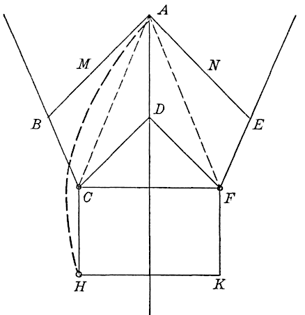
Fig. 23.
Referring to the last quotation, the writer would go further and say that if the assumption is true that the spaces above a tunnel are considered as a series of horizontal layers dependent on the natural coefficient of friction and cohesion (not added to by pressure) to hold them up, that it would appear to be far preferable to calculate always on full pressure to the top than to assume that some of these strata may be sustained by what would appear to the writer to be largely chance conditions.
It would appear that the author has considered cohesion and friction only as normally found in exposed faces, and as they would be developed between contiguous vertical columns of earth through which pressures were transmitted laterally; and, in tunnels as against vertical faces, he does not appear to have given sufficient weight to the essential factor that cohesion and friction, combined into what the writer has previously termed “cohesive friction,” are increased by the pressure in some definite relation to it.
If, for example, on a tunnel section, , Fig. 23, a centering or core of sand, , is assumed, and over this a mass, , composed of magnetic particles which cause them to adhere to each other, it is not difficult to conceive that a thickness at the key, , would be reached where the core, , could be removed. The same result, approximately, may be reached by assuming that the mass is sand or earth and is supported by the core, . As, however, in this case the lower part of the arch along is composed of loose material, the support of some of it must be provided for in the area where the blending of the arch and the core is indeterminate. This supported area is arbitrarily assumed to be , or half , the point, , being determined as far as possible by experiment to be at the intersection of the vertical, , and the line, , bisecting the angle between that of repose and the vertical. These general deductions, exclusive of the exact determination of the location of the point, , appear to be borne out by all the experiments previously noted and others in the writer’s papers hereinbefore referred to, and in the author’s observations on grain bins, as noted in the following quotation from his paper:
“In the many experiments on high grain bins, the enormous influence of the friction of the grain against the vertical walls or sides of the bin has been observed. In fact, the greater part of the weight of grain, even when running out, is sustained by the walls through this side friction. This furnishes another argument for including wall friction in a retaining-wall design.”
Not only is this “an argument for including wall friction,” but it seems to prove that this friction is increased relatively to the pressure, and that under stable conditions coherence is also induced by the pressure and friction.
The writer is much gratified to find that the author concurs in the view that the area of water pressure is reduced in subaqueous tunnels and other submerged structures in sand or earth, and he concurs heartily with the author that experiments on a large scale, to determine the values of this reduction definitely with relation to the various materials, will be of the greatest value to the Profession.
William Cain, M. Am. Soc. C. E. (by letter).—The writer is gratified by Mr. Worcester’s words of commendation. The walls or boards subjected to earth pressure were of various inclinations, and the surface slope of the earth was equally varied. A theory which stands the test of experiments in such variety seems to be pretty well established. If the various theories that have been proposed from time to time were subjected to this test, how many would survive? And yet no theory can claim to be a practical one unless it is found to agree fairly well with experiments. Mr. Worcester seems to think that the effect of time on retaining walls ought to be included. The effort was made to do this, by using a factor of safety and by multiplying only the normal component of the thrust on the wall by this factor, taken as 3 for ordinary cases; where the effect of frost is decided, the factor should be increased, and the back of the wall, for say 3 or 4 ft. down from the top, should be sloped forward to allow the earth, in the expansion incident to freezing, to push its way up the inclined plane corresponding.
If railway trains pass near a retaining wall, their weight should be replaced by an equal weight of earth, which is regarded as dead weight in computing the thrust. Vibration probably increases the thrust, and this increase moves the top of the wall over slightly, on account of the yielding of the earth foundation about the outer toe. On account of the imperfect elasticity of earth, this deformation may remain and increase in time, and thus lead to the ultimate failure of the wall. This lack of spring, or recovery, in the earth foundation, is probably the main cause of the increased leaning of walls with time. The remedy is to build a foundation course of masonry, projecting in front of the wall, of such width that the true resultant on its base shall pass through its center. The base, too, should be inclined, in order to prevent sliding. Of course, efficient drainage must be secured by the use of weep-holes and perhaps drains back of the wall.
Mr. Worcester is of the opinion that the friction against the back of the wall is not a permanent feature, and suggests the Rankine formula as possibly a better one for design. For a surcharge of sufficient inclination, and especially when it slopes at the angle of repose, the Rankine thrust involves more friction at the back of the wall than the method illustrated in Fig. 15, where only one-third of the friction is used for ordinary cases; but, even granting, for the sake of argument, that at some time this friction is null and that subsequently rains and vibration cause an increased thrust, then the top of the wall moves over slightly, the earth will again get its frictional grip on the wall, so that this friction is always exerted when required for stability.
It is, perhaps, customary to design a wall so that the resultant on its base shall pass one-third of the width of base from the outer toe. This procedure gives very different factors of safety, as hitherto defined, for different types of walls. The writer’s method aims to give equal security to all ordinary walls, by using a constant factor of safety.
The writer is gratified that Mr. Meem has again recorded some of his valuable experiences, but regrets that he cannot regard some of his theories as convincing. With regard to the center of pressure on a retaining wall backed by fresh earth, Mr. Meem maintains that the intensity of pressure increases from the bottom upward, so that the center of pressure lies above the horizontal plane drawn at mid-height. This view has been shown to be untrue by experiment. Thus:
(3) All the experiments discussed on pages 407–427 agree with the latter statement.
(4) The resultant earth thrust on a wall must approach indefinitely water thrust as approaches zero. The latter is known to act at one-third of the height above the base.
(5) If a triangular wedge of rupture is assumed, it follows inevitably that the unit pressure increases with the depth, and that the resultant acts at one-third of the height above the base. This follows because the total pressure then varies with the square of the height, as in water pressure.
(6) Let the contrary be assumed—that the pressure increases from the base upward—then, in a great depth of earth, the pressure at the top would be enormous enough to crush the hand if thrust in the earth. As everyone knows, the pressure on the hand is very slight, and this shows the absurdity of the hypothesis.
It may be stated now that the proposed experiment, referring to Fig. 22, would not prove Mr. Meem’s contention. For, if the earth below was removed, the thrust on would have to be sufficient to prevent the whole mass, , from descending, which is far greater than , which balances only the thrust of the wedge of rupture, the inclined base of which passes through .
A conclusive experiment could be made on a high retaining wall, backed by sand or grain (not in a bin, but unconfined except by the wall) after Jamieson’s manner in the case of grain bins, by inserting the rubber diaphragms, etc., at various points from the top down, and measuring the pressures.
In respect to the distribution of pressure, the theory of the sheeted trench differs materially from that of the retaining wall. Much confusion has arisen from confounding them. On that account, and to meet many interesting points made by Mr. Meem, the writer will give a thorough discussion of retaining walls and sheeted or unsheeted trenches, backed by coherent earth.
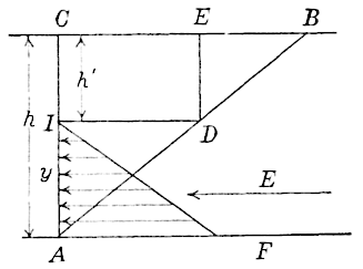
Fig. 24.
For an unlimited mass of level-topped earth, having both friction and cohesion, but ignoring the cohesion along the vertical plane, , Fig. 24, it was shown in the Appendix that the horizontal pressure on a vertical plane, , is that due to a certain prism, , and that its total amount, in pounds, is,
where is the weight in pounds of 1 cu. ft. of the earth, is the cohesion of the earth, in pounds per square foot, ,
The plane, , is found to bisect the angle between the natural slope and the vertical when is horizontal, as shown by Fig. 24.
The value of is given just below Equation (4) in the Appendix. It acts at above the base, since the distribution of stress on is linear.
It follows, because Equation (7) is the usual one for the thrust of non-coherent earth of depth , that the total horizontal stress on of the earth endowed with cohesion, is exactly the same as that due to the same earth, but devoid of cohesion, having a free horizontal surface, , extended indefinitely in both directions, at a depth , as given by Equation (8), below the original free surface. The theory ignores any possible cohesion acting upward along , or any tension in the mass that may possibly drag down part of the wedge, , and thus decrease the thrust, .
The formula is thus seen to give a thrust greater than the true one, or what may be called an upper limit. To realize the hypothesis more clearly, it may be said that if a vertical crack in the earth is assumed along , the resulting value of will be the same as that given by Equation (7). It is a fact of observation that sometimes earth which has been saturated and then dried out, cracks along one or more vertical planes. This indicates tension in the mass, which is overcome, however, at certain points (only) and thus vertical cracks appear.
In the construction of Fig. 11, the full friction and cohesion which can be exerted on the length, (of Fig. 24), is supposed to be exerted. This construction then gives a lower limit to the thrust. As to which hypothesis will lead to the most probable value, it may be observed that the broken line of rupture, , Fig. 24, is nearer the true curved line of rupture (which is assigned both by theory and the facts of observation) than the straight line, ; hence, the hypothesis leading to Equation (7) seems to be the more probable one.
In the case of the open trench, suppose to be a vertical side of the trench; if lies below the level of , and a crack exists along , then, undoubtedly, the mass, , will move to the left, because there is an unbalanced force, , to cause the motion.
The vertical height of an unsupported bank, where vertical cracks occur of depth , will then be that given by Equation (8), which is one-half the value usually given. This is generally an extreme lower value; for any earth endowed with much cohesion must be capable of exerting tension. If the tension exerted is sufficient to drag down (which can stand unsupported), that is, if the wedge, , acts as a whole, then the free unsupported height will be double that given by Equation (8). This is evidently an extreme upper limit, perhaps rarely attained; for vertical cracks have often been observed to precede a fall of earth into a vertical trench. For , , and ft., Equation (8) gives , whereas the usual equation gives lb. per sq. ft. The true value is possibly between these two extremes.
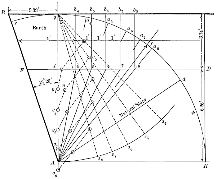
Fig. 25.
Recurring again to earth pressures, the discussion pertaining to Fig. 24 suggests the following modification of the graphical method of Fig. 11 to adapt it to finding the pressures of coherent earth against retaining walls, for the case supposed above. In Fig. 25, let be the inner face of a retaining board or wall, which is backed by earth with a horizontal surface . The vertical height of the wall is 10 ft. and the physical constants are assumed as follows: , , and . From Equation (8),
Now lay off, vertically downward from the free surface, a distance, ft. (to scale) and through draw a line, , parallel to the top surface. By Equation (7), the thrust on any vertical plane as , , ..., is null, and any tension and cohesion that may actually exist along any of these planes will be ignored. This is equivalent to supposing vertical cracks along these planes, which leads to an increase of the thrust and is thus on the side of safety.
The weights of the successive trial prisms of rupture, , , ..., are now laid off to scale, along some vertical, as . The successive weights are represented by the vertical lines, , , ..., . The points , , ..., were taken 1 ft. apart; hence the area, the area , etc.; so that, after computing the area , the areas , etc., can be found by successive additions. These areas, multiplied by 100, give the weights, in pounds, of the successive prisms of rupture for 1 ft. length of wall. As before, two arcs are drawn with the same radius (), with centers and and having laid off the angle, , the chords , , ..., are laid off equal to chords , , .... The lines, , , ..., now make angles with the normals to the planes, , , ..., respectively, each equal to . Also, lay off the chord, ; then gives the direction of the reaction of the wall, (directly opposed to the earth thrust), inclined at the angle, , to its normal.
Next, measure, to the scale of distance, the length, in feet, of any line of rupture, as . Multiply this number by , to get the force of cohesion, in pounds, acting up along , and lay it off, to the scale of force, from , on a line parallel to , to . Similarly, lay off the cohesive forces, acting along , , ..., at , , ..., and from points, such as , lines are drawn parallel to the direction of the thrust, , to the intersections with the corresponding rays, , , .... Suppose to prove the greatest of these segments, then , to the scale of force, gives the earth thrust on , in pounds. In the present instance, the plane of rupture lies midway between and , and the corresponding thrust is 1 440 lb. For purposes of illustration, regard as the plane of rupture; then the forces acting on the prism, , are represented by the sides of the closed polygon,
representing its weight, , the cohesion acting up along , the reaction of the wall, and the resultant of the normal reaction, , of the plane, , and the friction, , acting along it. As stated, the actual plane of rupture is found (by drawing one or more additional trial planes) to lie midway between and .
If it should be deemed desirable to include the cohesion acting upward along the vertical planes, , etc., it is very readily done. At each point, such as , draw vertically upward a line of length (to scale of force) lb., to represent the force of cohesion acting along the corresponding plane. From the extremities of such lines, parallels to are drawn to the intersections with the corresponding rays, of the type, . As before, the greatest of these lines represents the thrust on . Its amount, in this instance, is 1 240 lb. It is seen, especially when is one-half of or more, that the change in thrust is quite appreciable.
Lastly, if each plane, as , is extended to the surface and considered to offer full cohesive and frictional resistances throughout its whole extent, the construction of Fig. 11 applies, and gives a thrust of 1 220 lb., practically the previous amount.
As mentioned before, in connection with Fig. 24, this supposes sufficient tension in the mass to drag down the triangle, . Suppose, now, to be the face of a trench which will just stand unsupported for the height, , when the cohesion along , , ..., is included. Then, if, from the drying out of the earth, causing contraction near the surface and possibly changes in and , cracks occur along some of these planes, the resistance to motion of the corresponding prism of rupture is decreased, and the mass will move down, unless, in the meantime, sufficient bracing has been put in. This well illustrates what constructors tell us of the importance of getting in well-keyed-up bracing in time to prevent any crack from developing, which, as we have seen, largely increases the thrust. Even when cracks do not appear, a heavy rain, shortly after a trench is opened, is a frequent cause of falls; evidently because and possibly have been very materially decreased.
To compare the results of this very general graphical method with those given by analysis, as expressed by Equations (7) and (8), let be taken vertical or coinciding with , regard the thrust on as horizontal, and neglect any cohesion on the vertical planes, , etc. Then it is found, for the given constants, that the graphical method gives exactly the thrust (560 lb.) obtained from Equation (7). This result was foreseen.
It is likewise interesting to know, if the thrust on is taken as parallel to , or making the angle, , with the normal to , that the thrust on , as given by the construction, is again found to be the same (510 lb.) as that given by a well-known formula for the thrust on the plane, , for earth devoid of cohesion and having a free surface, . The importance of these conclusions lies in this: that for the wall vertical, the earth surface horizontal, the earth thrust being horizontal or otherwise, the shorter method is available. If preferred, the thrust on the wall, , for the earth devoid of cohesion, with the free surface, , for either direction of the thrust, can be evaluated by the graphical methods (page 404) hitherto given.
In Table 6 comparative results are given for various cases, including those already examined. Each retaining board was supposed to be 10 ft. high, the earth to have a natural slope of 1 on 1½, and to weigh 100 lb. per cu. ft.
TABLE 6.
Case..., in pounds per square foot., in pounds., in pounds.
1.–⅓01001 440880
2.001000560560
3.00100510510
4.0½100660750
5.0⅔1008801 630
6.+⅓05018°26′240490
It is seen, by comparing the values of and , in Table 6, that, except for Cases 2 and 3, where the coincidence in the results has been already noted, the thrusts by the two methods differ very widely, hence the second method must be rejected, as in some cases undervaluing the thrust, and in other cases overvaluing it. In Case 5, where the surcharge slopes at the angle of repose, the large excess is due principally to the ordinary theory for computing , involving an infinite plane of rupture, as hitherto noted.
In Case 6, where the top of the wall leaned toward the earth, was first assumed equal to 100, but it was found to give no thrust against the wall; which means that the earth would stand unsupported at the slope or with the face making an angle of 18°26' with the vertical, when this face was 10 ft. high. Hence, a second trial was made, with , with the results shown. It will be noticed that was assumed as 18°26', so that the thrust was taken horizontal. In fact, Résal asserts that the thrust against such a leaning wall, makes a less angle than with the normal to the wall. According to his tables, , for this wall cannot exceed 20°40'. As the wall approaches the vertical, , approaches , the exact value given for a vertical wall. By comparing the thrusts, , for Cases 1 and 6, the economy of using the latter type of wall is so apparent that it is astonishing that constructors do not adopt it oftener.
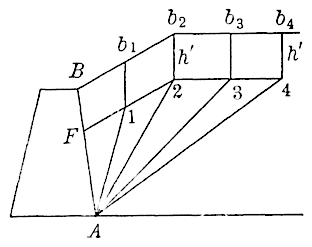
Fig. 26.
The general conclusion to be drawn from Table 6 is that, except for Cases 2 and 3, the general graphical method of Fig. 25 must be used for accuracy. If applicable to the case in hand, the cohesion along the vertical planes, , etc., can be included with very little additional labor. The graphical treatment given is so general and the theory involved is so apparent to the eye, that it seems to commend itself as a practical treatment of a very complicated problem.
The general method illustrated in Fig. 25 can also be applied to the surcharged wall of Fig. 26. Here, the lines, and , are drawn parallel, respectively, to and , and vertically, ft. below them. The trial prisms of rupture are of the type, . Their weights are laid off as before, on the line, , of Fig. 25, and the further construction is exactly as there indicated. It is assumed here that the slope of does not exceed the natural slope, for, if it does, the construction is somewhat altered.
It may be asked whether the construction of Fig. 25, where the cohesion on the vertical planes, , etc., is omitted, if applied to the experiments on rotating boards, will appreciably alter the results given in Table 3. The answer is no; for, when , , therefore ft., or is very small. In fact, as in the experiments, no cracks were formed, the cohesion on the vertical planes should be included, which would lead to the results given.
After the thrust, for earth endowed with cohesion, has been computed, the next question is, at what point on the retaining wall does it act? This can be answered at once, when the inner face of the wall is vertical and the earth surface horizontal, for then the earth thrust acts at of the height, , Figs. 24 and 25, as hitherto proved. The case is not so simple when the wall is inclined, either toward or from the earth. In Fig. 25, the thrust, , on the wall, , must be decomposed into horizontal and vertical components. The horizontal component is the resultant of the horizontal forces acting from to which may be assumed to follow the linear law; hence this component will act on at a point, distant from , going from to . The vertical component, similarly, will be regarded as acting on , at a distance from . The same approximate rule is suggested when lies to the right of the vertical, .
When the earth surface slopes at the angle of repose, the distribution of stress is not linear, but more like that shown in Fig. 10. As the equation of the corresponding pressure curve cannot be found, an approximation only can be suggested. When is (say) less than one or two tenths, the factor, , above, can be used; but as increases toward its limit, 1, the factor increases toward some unknown limit. Probably it does not exceed 0.4 even for Fig. 26, and, for want of accurate knowledge on the subject, it may be taken at 0.4 as a rude approximation.
Finally, when the surface slope is less than the natural slope of the earth, then as it decreases from to zero, the factor should. decrease from the extreme value (say 0.4) to . Résal takes this factor at for all cases, which is certainly not on the safe side.
The case of the retaining wall which receives the active thrust of the earth has been hitherto examined, and next the case of the braced trench will be discussed. As the trench (having vertical sides) is dug, the usual sheeting, rangers, and bracing are put in and the bracing is kept well keyed-up, so as to exert an active pressure on the earth. To illustrate the theory, in Fig. 25, let represent the vertical side of the trench, the earth extending only to the right of . Then from points such as , draw horizontal lines to the intersection with the corresponding s; the longest of these lines, to the scale of force, will represent the total force that must be exerted by all the braces, per foot of length of trench, to prevent any motion of the mass. As has been seen, this force is given by Equation (7). If a still greater force is exerted by the braces, less than a certain value which would just cause motion of the earth up some plane of rupture, stability is completely assured.
As a numerical illustration, assume a trench 40 ft. deep and 15 ft. wide, the constants for the earth being, , , . Then, by Equation (8), ft. and ft. Hence, by Equation (7), the least force the braces must exert per linear foot of trench is,
Suppose the braces to be 10 ft. apart horizontally, and that there are six braces in the same vertical plane. The least force that the horizontal braces must exert on 10 lin. ft. of trench is 188 440 lb., and if each carries the same stress, the force to be exerted by one, is lb. Assuming a unit stress of 800 lb. per sq. in. for an 8 by 8-in. wooden brace, 15 ft. long, it is seen that one brace can safely exert a force of 51200 lb., which is greater than the least amount required, as should be the case to allow for changes in and due to heavy rains. To meet such contingencies, 10 by 10-in. braces are suggested. Of course, very little is now known as to the coefficient, , but, from the observed heights of trenches which have stood without sheathing, it is probable that values of from 100 to 300 lb. per sq. ft. can be counted on for most trenching. For the present, the only safe way is to be guided by experience, such as has been elicited by Mr. Meem’s paper, “The Bracing of Trenches and Tunnels, With Practical Formulas for Earth Pressures.”
As to the exact distribution of the stresses, theory cannot speak definitely, for the conditions are different from those in the case of the retaining wall, the passive resistance of which opposes the active earth thrust. For the braced trench, the earth, at first, simply resists the active pressure exerted by the braces, when first put in and keyed-up tight, particularly on that upper portion where the active earth thrust is nothing or very small. As the construction proceeds, the braces will receive more and more of the active earth thrust, which necessarily increases with the depth of trench. In fact, the distribution of stress, indicated by the arrows in Fig. 24, although true in the case of a retaining wall, where the earth has been deposited behind it, is not necessarily or generally true in a sheeted trench, because of the manner of its construction. Thus, in digging a trench, the bracing is put in at intervals, but when a brace is inserted near the bottom of the trench, the digging is continued for several feet without bracing, until a depth is attained at which it is thought best to insert another brace. Before the latter is put in, the unprotected face of the trench, say 6 ft. in depth, can exert no pressure, as it would in the case of the retaining wall. The thrust that would be exerted, for this area, on the supposed wall, does not exist for the unsupported face of the trench, for the full horizontal thrust of the earth for the whole depth has been taken up by the braces above the unsupported area. This state of affairs is characteristic of the work as it proceeds, the lowest brace that is put in at first carries only the stress due to the keying-up, but takes more and more stress as the excavation proceeds. It can thus very well happen that the upper or the middle braces may receive more stress in the end, than the lower braces. In fact, this was asserted to be generally true, for well-drained material, by many engineers in the valuable discussion on Mr. Meem’s paper referred to. Other engineers advised caution in accepting this view, and asserted that in wet or saturated ground the lower braces were most severely stressed. If it were possible to force a board of a size equal to the length and depth of a trench, vertically downward, excavate and brace, all in a millionth of a second, then one can conceive that the distribution of stress shown in Fig. 24 might be realized; but, for trenches as actually constructed, the distribution of stress in the earth mass is very much altered from this, though it would appear that the total earth pressure would be given, at least approximately, by the construction of Fig. 25, or by the use of Equation (7).
The writer hopes that Mr. Meem may agree to the foregoing explanation, for the subject of trenches was entered into in great detail, in order to explain, if possible, all the facts, as presented by many engineers who held very diverse views about the explanation of them. Mr. Meem’s Fig. 22 can illustrate the writer’s view: if bracing only extends, say, from to , then the braces must exert sufficient horizontal thrust to prevent the descent of the wedge, say , if this gives the maximum thrust for the coherent earth.
Turning now to pressures on tunnels, the writer is pleased to note that Mr. Meem has recorded some more of his experiences concerning them. From lack of proper knowledge of the so-called constants, , and , such experience is an aid in leading to more probable values.
As the writer proceeds in this investigation, he hopes to make clear the conception of arch action alluded to, and will derive the limiting values of and in the simple manner outlined briefly in the Appendix. Before considering these matters, however, it may be well to call attention to the fact that a vertical prism of earth can be held up by the cohesion of its sides alone when is large enough. Take the vertical prism of depth and cross-section area , Fig. 20, its weight being . In a long tunnel, two sides only can be counted on to furnish cohesive forces. Call the perimeter available in any case. Then the cohesive force is , and this alone (without reference to any friction that may act) will support the prism when, . In the long or completed tunnel, (see notation of Appendix); but if we take a short section at the heading, say , then support can be derived from three sides, and . Thus if we assume the horizontal cross-section of the prism to be 15 by 7.5 ft., lb. per sq. ft., where lb. per cu. ft. Thus, such a vertical prism of any height, at the heading, can be sustained by a cohesion of 338 lb. per sq. ft. acting on three of its sides. This refers to a tunnel 15 ft. wide. For the completed tunnel 15 ft. wide, the part vertically over the tunnel can be supported if the two sides can furnish double this unit cohesion. The term will appear in an equation mentioned later. It is seen now that when this term is zero, cohesion alone can sustain the prism, and the pressure reduces to zero. When this term is negative, it indicates that that too large a value of has been assumed, for stability is assured for .
On substituting this value in the equation above, reducing and placing , we obtain,
where, .
In the Appendix, the writer assumed, , basing this value on the results pertaining to a smooth steel bin, 1 ft. in diameter, filled with sand. From the experiments of Jamieson on large wooden bins, about 12 by 12 ft., filled with wheat, was found to be 0.60. Janssen determined experimentally to be 0.67. For wheat, Jamieson gave ; whence . His experimental value was of this; hence, for lack of definite data, there will be assumed for earth,
From the last three equations, the values of and have been computed for various values of , , , and , and are given in Table 7.
TABLE 7.
, in pounds per square foot., in feet., in pounds per square foot., in pounds per square foot.
(1)(2)(3)(4)(5)(6)(7)
1001530°7401 7904101 000
1003030°1 7903 9001 0002 160
1001545°8302 010240570
1003045°2 0104 3705701 250
4001530°08600480
4003030°8602 9604801 640
4001545°09600270
4003045°9603 320270950
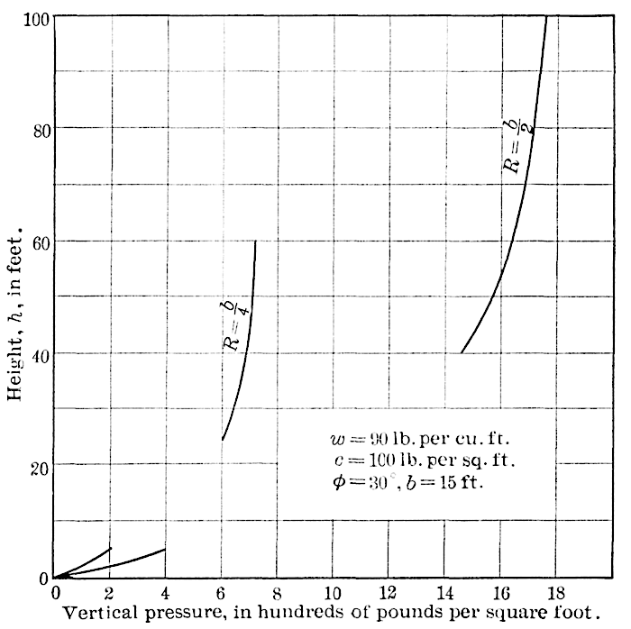
Fig. 27.
These are wide variations, resulting from variations in and the coefficient of friction of the wheat on the walls of the bin. As increases, this ratio of height to diameter decreases. It would appear to be a serious objection to the use of Equations and if this ratio for maximum was large, but it must be remembered that , for earth over tunnels, is not known. It is possibly larger than assumed. In any case, Equations (9), which were deduced independently of the modified Janssen formulas, appear to hold.
The writer has read with much interest the very interesting “dry sand and wheat arching experiments,” referred to by Mr. Meem. It is seen from the above, that the writer believes in this arching of sand under certain conditions, for example, after some settlement. He does not see any reason for any arching in an unlimited mass of sand, level at the top. The conjugate pressures here are vertical and horizontal; but, if a tunnel is bored through this mass, it tends to sink over the tunnel, and, only in consequence of that settlement, is a part of the weight of the sand directly over the tunnel transferred to the sides through the friction caused by the lateral thrust and the cohesion. Neither of these forces, both acting vertically upward, were in action, before the settlement. Mr. Meem gives the following account of an interesting experiment:
“A 2-in. pipe, 18 in. long, was filled with dry sand for a depth of 12 in., and a thin piece of tissue paper was pasted across the bottom. Then, with a wooden piston bearing on the sand, the latter would support the blow of a sledge hammer or the weight of a man without breaking the tissue paper.”
Considering the sand in the pipe alone, it affords a pretty illustration of the bin theory. Here, . Take and , ; also lb. per cu. in. Therefore, making in the formula for above, we have lb. per sq. in. Hence the total pressure on the tissue paper is lb., or say ¼ lb. Perhaps the paper can stand this. The pressure is reduced to 0.185 lb. on the paper if we include cohesion, taking lb. per sq. ft., as deduced from Leygue’s experiments on dry sand. This pressure would not be increased if the pipe, supposed to be vertical and filled with sand, was of great height, the weight of the additional sand being equal to the weight of the man or to the pressure induced by the blow of the hammer. It seems natural, then, to infer that the pressures due to the blow or man, are sustained by the sides of the pipe, as in the case of the sand, though the conditions are not the same. In fact, in this case, the pressure on the paper is even less than before; for the blow, or the weight of the man causes the passive lateral thrust of the earth to be exerted, and this, for , is nine times the active thrust hitherto used, at least for an unlimited mass of earth. If this ratio is assumed to hold for the sand in the pipe, the value of will be changed to , and the total pressure on the paper will be only
The writer returns sincere thanks to Messrs. Worcester and Meem for their helpful and stimulating discussion.
Equations and will not give accurate results for small, which is of no importance, as such values are never used; but they should give practically accurate results for the larger values of .] Return to text